EP4579889A2 - Zellenanordnung, sekundärbatteriepack damit und verfahren zur herstellung eines sekundärbatteriepacks damit - Google Patents
Zellenanordnung, sekundärbatteriepack damit und verfahren zur herstellung eines sekundärbatteriepacks damit Download PDFInfo
- Publication number
- EP4579889A2 EP4579889A2 EP24211444.5A EP24211444A EP4579889A2 EP 4579889 A2 EP4579889 A2 EP 4579889A2 EP 24211444 A EP24211444 A EP 24211444A EP 4579889 A2 EP4579889 A2 EP 4579889A2
- Authority
- EP
- European Patent Office
- Prior art keywords
- cell array
- cell
- electrode terminal
- busbar
- secondary battery
- Prior art date
- Legal status (The legal status is an assumption and is not a legal conclusion. Google has not performed a legal analysis and makes no representation as to the accuracy of the status listed.)
- Pending
Links
Images


Classifications
-
- H—ELECTRICITY
- H01—ELECTRIC ELEMENTS
- H01M—PROCESSES OR MEANS, e.g. BATTERIES, FOR THE DIRECT CONVERSION OF CHEMICAL ENERGY INTO ELECTRICAL ENERGY
- H01M50/00—Constructional details or processes of manufacture of the non-active parts of electrochemical cells other than fuel cells, e.g. hybrid cells
- H01M50/50—Current conducting connections for cells or batteries
- H01M50/528—Fixed electrical connections, i.e. not intended for disconnection
-
- H—ELECTRICITY
- H01—ELECTRIC ELEMENTS
- H01M—PROCESSES OR MEANS, e.g. BATTERIES, FOR THE DIRECT CONVERSION OF CHEMICAL ENERGY INTO ELECTRICAL ENERGY
- H01M50/00—Constructional details or processes of manufacture of the non-active parts of electrochemical cells other than fuel cells, e.g. hybrid cells
- H01M50/50—Current conducting connections for cells or batteries
-
- H—ELECTRICITY
- H01—ELECTRIC ELEMENTS
- H01M—PROCESSES OR MEANS, e.g. BATTERIES, FOR THE DIRECT CONVERSION OF CHEMICAL ENERGY INTO ELECTRICAL ENERGY
- H01M50/00—Constructional details or processes of manufacture of the non-active parts of electrochemical cells other than fuel cells, e.g. hybrid cells
- H01M50/20—Mountings; Secondary casings or frames; Racks, modules or packs; Suspension devices; Shock absorbers; Transport or carrying devices; Holders
- H01M50/244—Secondary casings; Racks; Suspension devices; Carrying devices; Holders characterised by their mounting method
-
- H—ELECTRICITY
- H01—ELECTRIC ELEMENTS
- H01M—PROCESSES OR MEANS, e.g. BATTERIES, FOR THE DIRECT CONVERSION OF CHEMICAL ENERGY INTO ELECTRICAL ENERGY
- H01M10/00—Secondary cells; Manufacture thereof
- H01M10/04—Construction or manufacture in general
-
- H—ELECTRICITY
- H01—ELECTRIC ELEMENTS
- H01M—PROCESSES OR MEANS, e.g. BATTERIES, FOR THE DIRECT CONVERSION OF CHEMICAL ENERGY INTO ELECTRICAL ENERGY
- H01M10/00—Secondary cells; Manufacture thereof
- H01M10/42—Methods or arrangements for servicing or maintenance of secondary cells or secondary half-cells
- H01M10/425—Structural combination with electronic components, e.g. electronic circuits integrated to the outside of the casing
-
- H—ELECTRICITY
- H01—ELECTRIC ELEMENTS
- H01M—PROCESSES OR MEANS, e.g. BATTERIES, FOR THE DIRECT CONVERSION OF CHEMICAL ENERGY INTO ELECTRICAL ENERGY
- H01M10/00—Secondary cells; Manufacture thereof
- H01M10/60—Heating or cooling; Temperature control
- H01M10/61—Types of temperature control
- H01M10/613—Cooling or keeping cold
-
- H—ELECTRICITY
- H01—ELECTRIC ELEMENTS
- H01M—PROCESSES OR MEANS, e.g. BATTERIES, FOR THE DIRECT CONVERSION OF CHEMICAL ENERGY INTO ELECTRICAL ENERGY
- H01M10/00—Secondary cells; Manufacture thereof
- H01M10/60—Heating or cooling; Temperature control
- H01M10/64—Heating or cooling; Temperature control characterised by the shape of the cells
- H01M10/647—Prismatic or flat cells, e.g. pouch cells
-
- H—ELECTRICITY
- H01—ELECTRIC ELEMENTS
- H01M—PROCESSES OR MEANS, e.g. BATTERIES, FOR THE DIRECT CONVERSION OF CHEMICAL ENERGY INTO ELECTRICAL ENERGY
- H01M10/00—Secondary cells; Manufacture thereof
- H01M10/60—Heating or cooling; Temperature control
- H01M10/65—Means for temperature control structurally associated with the cells
- H01M10/655—Solid structures for heat exchange or heat conduction
- H01M10/6551—Surfaces specially adapted for heat dissipation or radiation, e.g. fins or coatings
-
- H—ELECTRICITY
- H01—ELECTRIC ELEMENTS
- H01M—PROCESSES OR MEANS, e.g. BATTERIES, FOR THE DIRECT CONVERSION OF CHEMICAL ENERGY INTO ELECTRICAL ENERGY
- H01M10/00—Secondary cells; Manufacture thereof
- H01M10/60—Heating or cooling; Temperature control
- H01M10/65—Means for temperature control structurally associated with the cells
- H01M10/655—Solid structures for heat exchange or heat conduction
- H01M10/6554—Rods or plates
- H01M10/6555—Rods or plates arranged between the cells
-
- H—ELECTRICITY
- H01—ELECTRIC ELEMENTS
- H01M—PROCESSES OR MEANS, e.g. BATTERIES, FOR THE DIRECT CONVERSION OF CHEMICAL ENERGY INTO ELECTRICAL ENERGY
- H01M10/00—Secondary cells; Manufacture thereof
- H01M10/60—Heating or cooling; Temperature control
- H01M10/65—Means for temperature control structurally associated with the cells
- H01M10/655—Solid structures for heat exchange or heat conduction
- H01M10/6556—Solid parts with flow channel passages or pipes for heat exchange
- H01M10/6557—Solid parts with flow channel passages or pipes for heat exchange arranged between the cells
-
- H—ELECTRICITY
- H01—ELECTRIC ELEMENTS
- H01M—PROCESSES OR MEANS, e.g. BATTERIES, FOR THE DIRECT CONVERSION OF CHEMICAL ENERGY INTO ELECTRICAL ENERGY
- H01M50/00—Constructional details or processes of manufacture of the non-active parts of electrochemical cells other than fuel cells, e.g. hybrid cells
- H01M50/10—Primary casings; Jackets or wrappings
- H01M50/102—Primary casings; Jackets or wrappings characterised by their shape or physical structure
- H01M50/103—Primary casings; Jackets or wrappings characterised by their shape or physical structure prismatic or rectangular
-
- H—ELECTRICITY
- H01—ELECTRIC ELEMENTS
- H01M—PROCESSES OR MEANS, e.g. BATTERIES, FOR THE DIRECT CONVERSION OF CHEMICAL ENERGY INTO ELECTRICAL ENERGY
- H01M50/00—Constructional details or processes of manufacture of the non-active parts of electrochemical cells other than fuel cells, e.g. hybrid cells
- H01M50/20—Mountings; Secondary casings or frames; Racks, modules or packs; Suspension devices; Shock absorbers; Transport or carrying devices; Holders
- H01M50/204—Racks, modules or packs for multiple batteries or multiple cells
- H01M50/207—Racks, modules or packs for multiple batteries or multiple cells characterised by their shape
- H01M50/209—Racks, modules or packs for multiple batteries or multiple cells characterised by their shape adapted for prismatic or rectangular cells
-
- H—ELECTRICITY
- H01—ELECTRIC ELEMENTS
- H01M—PROCESSES OR MEANS, e.g. BATTERIES, FOR THE DIRECT CONVERSION OF CHEMICAL ENERGY INTO ELECTRICAL ENERGY
- H01M50/00—Constructional details or processes of manufacture of the non-active parts of electrochemical cells other than fuel cells, e.g. hybrid cells
- H01M50/50—Current conducting connections for cells or batteries
- H01M50/502—Interconnectors for connecting terminals of adjacent batteries; Interconnectors for connecting cells outside a battery casing
- H01M50/507—Interconnectors for connecting terminals of adjacent batteries; Interconnectors for connecting cells outside a battery casing comprising an arrangement of two or more busbars within a container structure, e.g. busbar modules
-
- H—ELECTRICITY
- H01—ELECTRIC ELEMENTS
- H01M—PROCESSES OR MEANS, e.g. BATTERIES, FOR THE DIRECT CONVERSION OF CHEMICAL ENERGY INTO ELECTRICAL ENERGY
- H01M50/00—Constructional details or processes of manufacture of the non-active parts of electrochemical cells other than fuel cells, e.g. hybrid cells
- H01M50/50—Current conducting connections for cells or batteries
- H01M50/502—Interconnectors for connecting terminals of adjacent batteries; Interconnectors for connecting cells outside a battery casing
- H01M50/509—Interconnectors for connecting terminals of adjacent batteries; Interconnectors for connecting cells outside a battery casing characterised by the type of connection, e.g. mixed connections
- H01M50/51—Connection only in series
-
- H—ELECTRICITY
- H01—ELECTRIC ELEMENTS
- H01M—PROCESSES OR MEANS, e.g. BATTERIES, FOR THE DIRECT CONVERSION OF CHEMICAL ENERGY INTO ELECTRICAL ENERGY
- H01M50/00—Constructional details or processes of manufacture of the non-active parts of electrochemical cells other than fuel cells, e.g. hybrid cells
- H01M50/50—Current conducting connections for cells or batteries
- H01M50/502—Interconnectors for connecting terminals of adjacent batteries; Interconnectors for connecting cells outside a battery casing
- H01M50/514—Methods for interconnecting adjacent batteries or cells
- H01M50/516—Methods for interconnecting adjacent batteries or cells by welding, soldering or brazing
-
- H—ELECTRICITY
- H01—ELECTRIC ELEMENTS
- H01M—PROCESSES OR MEANS, e.g. BATTERIES, FOR THE DIRECT CONVERSION OF CHEMICAL ENERGY INTO ELECTRICAL ENERGY
- H01M50/00—Constructional details or processes of manufacture of the non-active parts of electrochemical cells other than fuel cells, e.g. hybrid cells
- H01M50/50—Current conducting connections for cells or batteries
- H01M50/543—Terminals
- H01M50/547—Terminals characterised by the disposition of the terminals on the cells
- H01M50/548—Terminals characterised by the disposition of the terminals on the cells on opposite sides of the cell
-
- H—ELECTRICITY
- H01—ELECTRIC ELEMENTS
- H01M—PROCESSES OR MEANS, e.g. BATTERIES, FOR THE DIRECT CONVERSION OF CHEMICAL ENERGY INTO ELECTRICAL ENERGY
- H01M50/00—Constructional details or processes of manufacture of the non-active parts of electrochemical cells other than fuel cells, e.g. hybrid cells
- H01M50/50—Current conducting connections for cells or batteries
- H01M50/543—Terminals
- H01M50/564—Terminals characterised by their manufacturing process
- H01M50/566—Terminals characterised by their manufacturing process by welding, soldering or brazing
-
- H—ELECTRICITY
- H01—ELECTRIC ELEMENTS
- H01M—PROCESSES OR MEANS, e.g. BATTERIES, FOR THE DIRECT CONVERSION OF CHEMICAL ENERGY INTO ELECTRICAL ENERGY
- H01M10/00—Secondary cells; Manufacture thereof
- H01M10/60—Heating or cooling; Temperature control
- H01M10/65—Means for temperature control structurally associated with the cells
- H01M10/656—Means for temperature control structurally associated with the cells characterised by the type of heat-exchange fluid
- H01M10/6567—Liquids
-
- H—ELECTRICITY
- H01—ELECTRIC ELEMENTS
- H01M—PROCESSES OR MEANS, e.g. BATTERIES, FOR THE DIRECT CONVERSION OF CHEMICAL ENERGY INTO ELECTRICAL ENERGY
- H01M2220/00—Batteries for particular applications
- H01M2220/20—Batteries in motive systems, e.g. vehicle, ship, plane
-
- H—ELECTRICITY
- H01—ELECTRIC ELEMENTS
- H01M—PROCESSES OR MEANS, e.g. BATTERIES, FOR THE DIRECT CONVERSION OF CHEMICAL ENERGY INTO ELECTRICAL ENERGY
- H01M50/00—Constructional details or processes of manufacture of the non-active parts of electrochemical cells other than fuel cells, e.g. hybrid cells
- H01M50/20—Mountings; Secondary casings or frames; Racks, modules or packs; Suspension devices; Shock absorbers; Transport or carrying devices; Holders
- H01M50/249—Mountings; Secondary casings or frames; Racks, modules or packs; Suspension devices; Shock absorbers; Transport or carrying devices; Holders specially adapted for aircraft or vehicles, e.g. cars or trains
-
- Y—GENERAL TAGGING OF NEW TECHNOLOGICAL DEVELOPMENTS; GENERAL TAGGING OF CROSS-SECTIONAL TECHNOLOGIES SPANNING OVER SEVERAL SECTIONS OF THE IPC; TECHNICAL SUBJECTS COVERED BY FORMER USPC CROSS-REFERENCE ART COLLECTIONS [XRACs] AND DIGESTS
- Y02—TECHNOLOGIES OR APPLICATIONS FOR MITIGATION OR ADAPTATION AGAINST CLIMATE CHANGE
- Y02E—REDUCTION OF GREENHOUSE GAS [GHG] EMISSIONS, RELATED TO ENERGY GENERATION, TRANSMISSION OR DISTRIBUTION
- Y02E60/00—Enabling technologies; Technologies with a potential or indirect contribution to GHG emissions mitigation
- Y02E60/10—Energy storage using batteries
Definitions
- aspects of embodiments of the present disclosure relate to a cell array assembly, a secondary battery pack including the same, and a method of manufacturing a secondary battery pack including the same.
- a secondary battery refers to a rechargeable battery that may be charged and discharged multiple times. Secondary batteries are mainly used in various suitable applications, such as for various suitable electronics (e.g., smartphones, laptops, and tablets), electric vehicles, solar power generation, and emergency power supplies. As an example, lithium-ion batteries have high energy density and high charge and discharge efficiency, and thus, may be used in various suitable electronic products and electric vehicles.
- a secondary battery may be disposed in a product, such as an electric vehicle, in the form of a secondary battery pack.
- a secondary battery pack may include a plurality of secondary battery modules, a cell protection device, and a control device, and may be disposed in an electric vehicle.
- a secondary battery module including an assembly of unit cells packaged within a case may be provided, and a plurality of secondary battery modules may be disposed within a pack housing together with the protection device and the control device.
- CTP cell-to-pack
- Secondary battery packs without the module structure may have reduced structural strength, so it may be desired to increase the structural strength of such secondary battery packs without the module structure. Further, it may be desired to improve the energy density by increasing the density of unit cells within the secondary battery pack.
- Embodiments of the present disclosure may be directed to a cell array assembly, a secondary battery pack including the same, and a method of manufacturing a secondary battery pack including the same.
- a secondary battery pack includes: a plurality of cell arrays, each including a plurality of unit cells located in series along a first direction; and a frame configured to include the cell arrays.
- Each of the unit cells includes: a first surface having a long side extending in the first direction; a second surface opposite to the first surface and having a long side extending in the first direction; a third surface perpendicular to the first surface and in contact with the long side of the first surface and the long side of the second surface; a fourth surface opposite to the third surface and in contact with another long side of the first surface and another long side of the second surface; a first side surface in contact with short sides of the first to fourth surfaces; a second side surface opposite to the first side surface; a first electrode terminal on the first side surface; and a second electrode terminal on the second side surface.
- the cell arrays may include a first cell array and a second cell array, and the cell arrays may be located within the frame so that the third surface of a 1_1 st unit cell of the first cell array faces the fourth surface of a 2_1st unit cell of the second cell array.
- the first electrode terminal of the 1_1st unit cell of the first cell array may be electrically connected to the second electrode terminal of a 1_2nd unit cell of the first cell array that are adjacent to each other in the first direction.
- the plurality of cell arrays comprises a first cell array and a second cell array
- the plurality of unit cells of the first cell array comprises a 1_1 st unit cell and a 1_2nd unit cell
- a first electrode terminal of the 1_1st unit cell is electrically connected to a second electrode terminal of the 1_2nd unit cell, both unit cells are (directly) adjacent to each other in the first direction (X-axis).
- the first electrode terminal of the 1_1st unit cell and the second electrode terminal of the 1_2nd unit cell may be electrically connected to each other by a junction located therebetween.
- the plurality of cell arrays comprises a first cell array and a second cell array
- the secondary battery pack further comprises a cooling plate between the first cell array and the second cell array
- the secondary battery pack may further include a cooling plate between the first cell array and the second cell array.
- the cell arrays may include a first cell array, and a second cell array adjacent to the first cell array.
- the cell arrays may be located so that an electrode polarity of an outermost unit cell of the first cell array in the first direction is different from an electrode polarity of an outermost unit cell of the second cell array in the first direction.
- the busbar assembly may include: a first busbar coupled to the first electrode terminal of the outermost unit cell of the first cell array; a second busbar connecting the first busbar and the frame to each other; a third busbar coupled to the second electrode terminal of the outermost unit cell of the second cell array; a fourth busbar connecting the third busbar and the frame to each other; and a fifth busbar connecting the second busbar and the fourth busbar to each other.
- the busbar assembly may include: a first busbar coupled to the first electrode terminal of the outermost unit cell of the first cell array; and a third busbar coupled to the second electrode terminal of the outermost unit cell of the second cell array.
- the first busbar and the third busbar may be connected in series.
- the secondary battery pack may further include a battery management device electrically connected to the first cell array by: a first busbar coupled to the first electrode terminal of the outermost unit cell of the first cell array; and a second busbar connecting the first busbar and the frame to each other.
- a battery management device electrically connected to the first cell array by: a first busbar coupled to the first electrode terminal of the outermost unit cell of the first cell array; and a second busbar connecting the first busbar and the frame to each other.
- the cell arrays may include the first cell array to an n th cell array sequentially located in a direction perpendicular to the first direction, where n may be a natural number greater than 1, for example greater than 2, and the battery management device may be electrically connected to the first electrode terminal of the outermost unit cell of the first cell array and the second electrode terminal of the outermost unit cell of the n th cell array.
- a cell array assembly includes: a first cell array including a plurality of unit cells located in series along a first direction; and a second cell array including a plurality of unit cells located in series along the first direction, the second cell array being adjacent to the first cell array in a direction perpendicular to the first direction.
- Each of the unit cells includes: a first surface having a long side extending in the first direction; a second surface opposite to the first surface, and having a long side extending in the first direction; a third surface perpendicular to the first surface, and in contact with the long side of the first surface and the long side of the second surface; a fourth surface opposite to the third surface, and in contact with another long side of the first surface and another long side of the second surface; a first side surface in contact with short sides of the first to fourth surfaces; a second side surface opposite to the first side surface; a first electrode terminal on the first side surface; and a second electrode terminal on the second side surface.
- the first and second cell arrays may be located so that the third surface of a 1_1st unit cell of the first cell array faces the fourth surface of a 2_1 st unit cell of the second cell array.
- the first electrode terminal of the 1_1st unit cell of the first cell array and the second electrode terminal of a 1_2nd unit cell of the first cell array may be adjacent to each other in the first direction to be electrically connected to each other by a junction therebetween.
- the junction may have a structure defined by brazing, laser brazing, welding, or soldering.
- the cell array assembly may further include a cooling plate between the first cell array and the second cell array.
- a method of manufacturing a secondary battery pack includes: forming a cell array by electrically connecting a first electrode terminal of one unit cell and a second electrode terminal of another adjacent unit cell to each other from among a plurality of unit cells; containing a plurality of cell arrays including the cell array within a frame; and electrically connecting the cell arrays to each other.
- Each of the unit cells includes: a first electrode terminal in a first side surface; and a second electrode terminal in a second side surface opposite to the first side surface.
- a cell array may be provided by electrically connecting a plurality of unit cells by welding.
- the cell array may be provided without connecting members, such as busbars, to reduce the weight of a secondary battery pack, thereby increasing the energy density.
- a cell array may be provided by connecting in series unit cells, each provided with two different electrode terminals on opposite sides thereof, and a cooling plate facing one side surface of the cell array extending in the longitudinal direction may be inserted and disposed perpendicularly or substantially perpendicularly in the frame of the pack, thereby increasing the structural strength of a secondary battery pack.
- a specific process order may be different from the described order.
- two consecutively described processes may be performed at the same or substantially at the same time, or may be performed in an order opposite to the described order.
- the x-axis, the y-axis, and the z-axis are not limited to three axes of the rectangular coordinate system, and may be interpreted in a broader sense.
- the x-axis, the y-axis, and the z-axis may be perpendicular to or substantially perpendicular to one another, or may represent different directions from each other that are not perpendicular to one another.
- any numerical range disclosed and/or recited herein is intended to include all sub-ranges of the same numerical precision subsumed within the recited range.
- a range of "1.0 to 10.0" is intended to include all subranges between (and including) the recited minimum value of 1.0 and the recited maximum value of 10.0, that is, having a minimum value equal to or greater than 1.0 and a maximum value equal to or less than 10.0, such as, for example, 2.4 to 7.6.
- Any maximum numerical limitation recited herein is intended to include all lower numerical limitations subsumed therein, and any minimum numerical limitation recited in this specification is intended to include all higher numerical limitations subsumed therein.
- references to two compared elements, features, and the like as being “the same” may mean that they are “substantially the same”.
- the phrase “substantially the same” may include a case having a deviation that is considered low in the art, for example, such as a deviation of 5% or less.
- a certain parameter when referred to as being uniform in a given region, it may mean that it is uniform in terms of an average.
- first,” “second,” “third,” etc. may be used herein to describe various elements, components, regions, layers and/or sections, these elements, components, regions, layers and/or sections should not be limited by these terms. These terms are used to distinguish one element, component, region, layer or section from another element, component, region, layer or section. Thus, a first element, component, region, layer or section described below could be termed a second element, component, region, layer or section, without departing from the spirit and scope of the present disclosure.
- the expression "A and/or B” denotes A, B, or A and B. Expressions such as “at least one of,” when preceding a list of elements, modify the entire list of elements and do not modify the individual elements of the list. For example, the expression “at least one of a, b, or c,” “at least one of a, b, and c,” and “at least one selected from the group consisting of a, b, and c" indicates only a, only b, only c, both a and b, both a and c, both b and c, all of a, b, and c, or variations thereof.
- the term “substantially,” “about,” and similar terms are used as terms of approximation and not as terms of degree, and are intended to account for the inherent variations in measured or calculated values that would be recognized by those of ordinary skill in the art. Further, the use of “may” when describing embodiments of the present disclosure refers to “one or more embodiments of the present disclosure.” As used herein, the terms “use,” “using,” and “used” may be considered synonymous with the terms “utilize,” “utilizing,” and “utilized,” respectively.
- FIG. 1 is a perspective view illustrating a unit cell 100 according to one or more embodiments of the present disclosure.
- the unit cell 100 may include one or more electrode assemblies, a case 110, a first cap plate 120, a second cap plate opposite to the first cap plate 120, a first electrode terminal 130, and a second electrode terminal.
- Each of the one or more electrode assemblies may be wound or stacked, with a separator formed of an insulation material provided between a positive electrode and a negative electrode.
- the case 110 may contain the one or more electrode assemblies therein.
- the positive electrode and the negative electrode may be wound after interposing the separator therebetween, which may be an insulator.
- the electrode assembly may have a stacked structure in which a positive electrode and a negative electrode, each including (e.g., made of) a plurality of sheets, are alternately stacked with a separator interposed therebetween.
- the case 110 may form the overall outer appearance of the unit cell 100, and may include (e.g., may be made of) a conductive metal, such as aluminum, an aluminum alloy, or a nickel-plated steel.
- the case 110 may provide a space (e.g., an internal space) in which the electrode assembly is accommodated.
- the first electrode terminal 130 may be positioned on the first cap plate 120 to be electrically connected to a first electrode tab of the electrode assembly, and may extend through the first cap plate 120.
- the second electrode terminal may be positioned on the second cap plate to be electrically connected to a second electrode tab of the electrode assembly, and may extend through the second cap plate.
- FIG. 1 illustrates the first electrode terminal 130 as a negative electrode terminal and the second electrode terminal as a positive electrode terminal.
- the case 110 including the opposite open sides is described with reference to FIG. 1 as an example, the present disclosure is not limited thereto, and the shape of the case 110 may be variously modified into various suitable shapes as needed or desired.
- the case 110 may have a first side that is open, and the remaining sides of the case 110 may be integrated with each other (e.g., may be integrally formed).
- the cap plate may seal the open first side, and a second side opposite to the open first side may be provided with an electrode terminal that may be electrically connected to an electrode tab of an electrode assembly.
- a vent 140 may be provided in at least one side of the unit cell 100 (e.g., the top surface of the unit cell 100).
- the vent 140 may be opened in response to an internal pressure of the unit cell 100 being (e.g., detected to be) at a critical pressure (e.g., a predetermined critical pressure) or higher.
- the vent 140 may include a notch.
- the notch may be removed from a first surface or side of the unit cell 100 (e.g., a first surface 111 in FIG. 2 ) to a thickness (e.g., a predetermined thickness), or may include (e.g., may be) at least one recess.
- the notch may be ruptured in a case where the internal pressure of the unit cell 100 exceeds the critical pressure.
- the unit cell 100 may be a lithium battery cell, a sodium battery cell, or the like. However, the present disclosure is not limited thereto, and the unit cell 100 may include any suitable kind of cell capable of repeatedly providing electricity by being charged and discharged.
- the unit cell 100 in a case where the unit cell 100 is the lithium battery cell, the unit cell 100 may be used in an electric vehicle (EV) due to superior lifetime and high rate characteristics.
- the unit cell 100 may be used in a hybrid vehicle, such as a plug-in hybrid electric vehicle (PHEV).
- the lithium battery cell may be used in a field in which a large amount of power storage is used or desired.
- the lithium battery cell may be used in an electric bicycle, a power tool, and the like.
- the unit cell 100 may include the first surface 111, a second surface 112, a third surface 113, a fourth surface 114, a first side surface 115, and a second side surface 116.
- the first surface 111 may be a top surface (e.g., a top view) of the unit cell 100.
- the first surface 111 may include long sides extending in a first direction (e.g., the X-axis), and short sides extending in a second direction (e.g., the Y-axis).
- the first surface 111 may have a rectangular shape.
- the first direction (X-axis) may be the longitudinal direction of the unit cell 100.
- the first direction (X-axis) may be perpendicular to or substantially perpendicular to the second direction (Y-axis).
- the first direction (X-axis) may be the longitudinal direction of the unit cell 100
- the second direction (Y-axis) may be the width direction of the unit cell 100.
- the vent 140 e.g., see FIG. 1
- the first surface 111 may be provided in the first surface 111.
- the second surface 112 may be a bottom surface (e.g., a bottom view) of the unit cell 100.
- the second surface 112 may include long sides extending in the first direction (X-axis), and short sides extending in the second direction (Y-axis).
- the second surface 112 may have a rectangular shape.
- the second surface 112 may be opposite to the first surface 111.
- the second surface 112 may be opposite to the first surface 111 in a third direction (e.g., the Z-axis).
- the third direction (Z-axis) may be perpendicular to or substantially perpendicular to the first direction (X-axis) and the second direction (Y-axis).
- the third direction (Z-axis) may be the height direction of the unit cell 100.
- the length of the long side of the first surface 111 may be the same or substantially the same as the length of the long side of the second surface 112.
- the length of the short side of the first surface 111 may be the same or substantially the same as the length of the short side of the second surface 112.
- the first surface 111 and the second surface 112 may have the same or substantially the same shape as each other.
- the third surface 113 may be a front surface (e.g., a front view) of the unit cell 100.
- the third surface 113 may include long sides extending in the first direction (X-axis), and short sides extending in the third direction (Z-axis).
- the third surface 113 may have a rectangular shape.
- the third surface 113 may be in contact with the long sides of the first surface 111 and the second surface 112. In other words, one of the long sides of the third surface 113 may be in contact with one of the long sides of the first surface 111, and the other of the long sides of the third surface 113 may be in contact with one of the long sides of the second surface 112.
- the length of the short side of the third surface 113 may be longer than the length of the short side of the first surface 111.
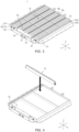
- FIG. 3 is a perspective view illustrating a secondary battery pack 1 according to one or more embodiments of the present disclosure.
- FIG. 4 illustrates a method of placing a plurality of cell arrays 10 within a frame 20 according to one or more embodiments of the present disclosure.
- One cell array and the other adjacent cell array from among the cell arrays 10 may be arranged so that the outermost unit cells thereof in the same direction have different electrical polarities from each other.
- one cell array and the other adjacent cell array may be arranged so that the electrode polarity of the outermost unit cell of a first cell array 10a in the first direction (X-axis) is different from the electrode polarity of the outermost unit cell of a second cell array 10b in the first direction (X-axis). This will be described in more detail below with reference to FIG. 9 .
- the cell arrays 10 may be inserted and contained within the frame 20.
- the frame 20 may include a pair of end plates 24 facing outermost cell arrays 10a and 10c, a pair of side plates 22 connected (e.g., coupled or attached) perpendicularly to the end plates 24, and a bottom plate 26 connected to (e.g., coupled to or attached to) the end plates 24 and the side plates 22 to form a lower portion of the frame 20.
- the cell array 10 and the battery management device 30 may be disposed on the frame 20.
- the cell arrays 10 may be inserted in the third direction (Z-axis) and disposed in the frame 20 so that the cell arrays 10 are perpendicular to or substantially perpendicular to the bottom plate 26.
- the first cell array 10a and the second cell array 10b included in the cell arrays 10 may be disposed in the frame 20, so that a third surface (e.g., 113 in FIG. 2 ) of a 1_1st unit cell 102a of the first cell array 10a faces a fourth surface (e.g., 114 in FIG. 2 ) of a 2_1st unit cell 102b of the second cell array 10b.
- the battery management device 30 may be a device for managing and controlling the charge/discharge of each of the unit cells 100.
- the battery management device 30 may measure a voltage, a temperature, a current, and/or the like of the unit cells 100, and may adjust a voltage balance between the unit cells 100.
- the battery management device 30 may protect the unit cells 100 in the event of an abnormal condition, such as an overvoltage, an undervoltage, or a short circuit, in the unit cells 100.
- the battery management device 30 may be in communication with a vehicle to transmit states of the unit cells 100 and/or receive information from the vehicle.
- the battery management device 30 may be disposed between the cell array 10c and the corresponding end plate 24.
- the end plates 24 may be configured into a shape corresponding to the outer shape of the battery management device 30 by fitting a plurality of subplates together.
- the battery management device 30 may include a connector 32 connected to an external device such as a vehicle.
- each of the end plates 24 may include a through-hole through which the connector 32 extends.
- the secondary battery pack 1 may further include a heat transfer material 16 (e.g., see FIG. 11 ) between a corresponding cooling plate 12 and a cell array facing the corresponding cooling plate 12.
- the heat transfer material may be disposed in at least one position between the first cell array 10a and the cooling plate 12, or between the second cell array 10b and the cooling plate 12.
- the heat transfer material may be disposed between the first cell array 10a and the cooling plate 12, or between the second cell array 10b and the cooling plate 12.
- the heat transfer material may be disposed between the first cell array 10a and the cooling plate 12, and between the second cell array 10b and the cooling plate 12.
- the structural strength of the secondary battery pack may be increased without a module frame for providing structural support between the unit cells.
- the secondary battery pack may be mounted on a vehicle.
- the vehicle may be, for example, an electric vehicle, a hybrid vehicle, or a plug-in hybrid vehicle.
- the vehicle may include a four-wheeled vehicle or a two-wheeled vehicle.
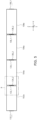
- the cell array 10a may include the unit cells 102a, 104a, 106a, and 108a arranged in series along the first direction (X-axis).
- the cell array 10 may be provided by electrically connecting the first electrode terminal of one unit cell from among the unit cells to the second electrode terminal of an adjacent unit cell.
- the first electrode terminal 132_1 of the 1_1st unit cell 102a may be electrically connected to the second electrode terminal 134_2 of the 1_2nd unit cell 104a.
- the first electrode terminal 134_1 of the 1_2nd unit cell 104a may be electrically connected to the second electrode terminal 136_2 of the 1_3rd unit cell 106a.
- the first electrode terminal 136_1 of the 1_3rd unit cell 106a may be connected to the second electrode terminal 138_2 of the fourth unit cell 108a.
- each of the second electrode terminal 132_2 of the first unit cell 102a and the first electrode terminal 138_1 of the fourth unit cell 108a may be electrically connected to an electrode terminal of another neighboring (e.g., adjacent) unit cell.
- a first electrode terminal of one unit cell and a second electrode terminal of an adjacent unit cell may be electrically connected to each other by welding.
- the first electrode terminal 132_1 of the 1_1st unit cell 102a of the first cell array 10a may be arranged to be electrically connected by welding to the second electrode terminal 134_2 of the 1_2nd unit cell 104a adjacent to the 1_1st unit cell 102a in the first direction (X-axis).
- a junction 14 may be included between the first electrode terminal 132_1 of the 1_1st unit cell 102a and the second electrode terminal 134_2 of the 1_2nd unit cell 104a.
- the junction 14 may be formed by brazing, laser brazing, welding, or soldering.
- the junction 14 may be one of a brazing junction, laser brazing junction, welding junction, or soldering junction.
- the cell array may be provided without additional connecting members, such as busbars, to reduce the weight of the secondary battery pack, thereby increasing the energy density.
- FIG. 7 illustrates an example of the cell array assembly including the cell arrays 10 according to one or more embodiments of the present disclosure.
- FIG. 8 illustrates an example of the cell array assembly including a busbar assembly according to one or more embodiments of the present disclosure.
- FIG. 9 illustrates an example of an electrical connection configuration of the cell array assembly and the battery management device 30 according to one or more embodiments of the present disclosure.
- the cell array assembly may refer to an assembly of the cell arrays 10. In some embodiments, the cell array assembly may refer to a configuration of the secondary battery pack 1 excluding the frame 20 and the battery management device 30.
- the cell arrays 10 of the cell array assembly may be arranged in a direction so that the wide surfaces (e.g., the third surface 113 or the fourth surface 114 in FIG. 2 ) face each other.
- the first cell array 10a and the second cell array 10b may be disposed adjacent to each other.
- each of the first cell array 10a and the second cell array 10b may include a plurality of unit cells 100 arranged in series along the first direction (X-axis), and the second cell array 10b may be disposed adjacent to the first cell array 10a in a direction perpendicular to or substantially perpendicular to the first direction (X-axis).
- the third surface of a unit cell of the first cell array 10a may be disposed to face the fourth surface of a unit cell of the second cell array 10b.
- each of the cell arrays 10a and 10b may be electrically connected to each other by the method described above with reference to FIGS. 5 and 6 , and thus, redundant description may not be repeated.
- the cell array assembly may include a busbar assembly electrically connecting the cell arrays to one another.
- the busbar assembly may include a first busbar 42a connected to (e.g., coupled to or attached to) the first electrode terminal of the outermost unit cell of the first cell array 10a, a second busbar 44a connecting the first busbar 42a to the frame 20, a third busbar 42b connected to (e.g., coupled to or attached to) the second electrode terminal of the outermost unit cell of the second cell array 10b, a fourth busbar 44b connecting the third busbar 42b to the frame 20, and a fifth busbar 46 connecting the second busbar 44a and the fourth busbar 44b to each other.
- the busbar assembly may include a first busbar 42a connected to (e.g., coupled to or attached to) the first electrode terminal of the outermost unit cell of the first cell array, a third busbar 42b connected to (e.g., coupled to or attached to) the second electrode terminal of the outermost unit cell of the second cell array, and the first busbar 42a and the third busbar 42b may be directly connected to each other.
- the busbar assembly may further include a busbar holder 50 holding a plurality of busbars 40 connected to (e.g., coupled to or attached to) the electrode terminals of the outermost unit cells of the cell arrays 10.
- the busbars 40 may be received in a receiving hole formed in the busbar holder 50.
- opposite ends of the busbar holder 50 may be connected to (e.g., coupled to or attached to) respective cooling plates attached to respective cell arrays disposed on opposite ends to hold the busbars 40.
- the cell array assembly may be electrically connected to the battery management device 30.
- the battery management device 30 may be electrically connected to the first cell array 10a by the first busbar 42a connected to (e.g., coupled to or attached to) the first electrode terminal of the outermost unit cell of the first cell array 10a, and the second busbar 44a connecting the first busbar 42a to the frame 20.
- the first cell array 10a may be a cell array arranged facing the end plate.
- the cell arrays 10 may include first to n th cell arrays 10a to 10c arranged sequentially in a direction (e.g., the Y-axis) perpendicular to or substantially perpendicular to the first direction (X-axis), where n is a natural number greater than 1.
- the battery management device 30 may be electrically connected to the first electrode terminal of the outermost unit cell of the first cell array 10a and the second electrode terminal of the outermost unit cell of the n th cell array 10c.
- an odd number of cell arrays e.g. 9 cell arrays
- an even number of cell arrays e.g., 10 cell arrays
- the battery management device may be connected to the unit cell disposed at the lower left and the unit cell disposed at the lower right (e.g., based on FIG. 9 ).
- the connection between the battery management device and the unit cells may be simplified.
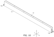
- FIG. 10 illustrates an example of the cell array assembly to which the cooling plates 12 are attached, according to one or more embodiments of the present disclosure.
- the cell array assembly may include a plurality of cell arrays 10, and a cooling plate 12 attached on at least one surface of the cell arrays 10.
- the cooling plate 12 may be attached to the first cell array 10a to face a surface extending in the longitudinal direction of the first cell array 10a (e.g., the first direction (X-axis)).
- the cooling plate 12 may cool the unit cells 100 using cooling water flowing through flow paths provided therein.
- the cooling plate 12 may include at least one inlet 12a through which cooling water enters the cooling plate 12, and at least one outlet 12b through which cooling water exits the cooling plate 12.
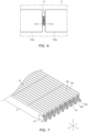
- FIG. 11 illustrates an example of the cell array assembly including a heat transfer material 16 according to one or more embodiments of the present disclosure.
- the cell array assembly may include a plurality of cell arrays 10, cooling plates 12 attached to at least one surface of each of the cell arrays 10, and at least one heat transfer material 16 disposed between the cell arrays 10 and the cooling plates 12.
- the cell array assembly may further include the heat transfer material 16 disposed in at least one position between the first cell array 10a (e.g., see FIG. 7 ) and the cooling plates 12, or between the second cell array 10b and the cooling plates 12.
- the heat transfer material 16 may be disposed between the first cell array 10a and the cooling plates 12 or between the second cell array 10b and the cooling plates 12.
- the heat transfer material 16 may be disposed between the first cell array 10a and the cooling plate 12 and between the second cell array 10b and the cooling plate 12.
- the heat transfer material 16 may be disposed between the cell array 10 and the cooling plates 12.
- areas to which the at least one heat transfer material 16 is applied may be configured such that the sizes thereof correspond to the sizes of the third surface 113 (e.g., see FIG. 1 ) and the fourth surface 114 of the unit cell 100.
- FIG. 12 is a flowchart illustrating a method 1200 of manufacturing a secondary battery pack according to one or more embodiments of the present disclosure.
- the method 1200 of manufacturing a secondary battery pack may be performed by an apparatus for manufacturing a secondary battery pack or the like (hereinafter, referred to as a manufacturing apparatus).
- a manufacturing apparatus may form a plurality of cell arrays by electrically connecting a first electrode terminal of one unit cell and a second electrode terminal of another adjacent unit cell among a plurality of unit cells to each other (S1210).
- the manufacturing apparatus may electrically connect the first electrode terminal of one unit cell from among the unit cells and the second electrode terminal of the other adjacent unit cell from among the unit cells to each other by welding.
- the manufacturing apparatus may attach a cooling plate to a first side surface of at least one cell array from among the cell arrays, extending in the longitudinal direction of the cell array.
- the manufacturing apparatus may further place a heat transfer material between a first side surface of at least one unit cell of the unit cells, extending in longitudinal direction of the unit cell, and the cooling plate.
- the manufacturing apparatus may contain (e.g., may insert or place) the cell arrays within a frame (S1220).
- the manufacturing apparatus may place the cell arrays within the frame in a direction perpendicular to or substantially perpendicular to the bottom of the frame.
- the cell arrays may be arranged so that a second surface 112 or a fourth surface 114 of each unit cell of the cell array faces the bottom of the frame.
- one cell array and another adjacent cell array from among the cell arrays may be arranged so that the outermost unit cells have different electrode polarities.
- the cell arrays may include a first cell array, and a second cell array adjacent to the first cell array.
- the manufacturing apparatus may arrange the cell arrays so that the electrode polarity of the outermost unit cell of the first cell array in a single direction is different from the electrode polarity of the outermost unit cell of the second cell array in the single direction.
- the manufacturing apparatus may electrically connect the cell arrays to each other (S1230).
- the manufacturing apparatus may connect a first busbar connected to (e.g., coupled to or attached to) the first electrode terminal of the outermost unit cell of the first cell array to the frame by a second busbar.
- the manufacturing apparatus may connect a third busbar connected to (e.g., coupled to or attached to) the second electrode terminal of the outermost unit cell of the second cell array to the frame by a fourth busbar.
- the manufacturing apparatus may connect the second busbar and the fourth busbar to each other by a fifth busbar.
- the manufacturing device may electrically connect the first electrode terminal of the outermost unit cell of the first cell array and the second electrode terminal of the outermost unit cell of the n th cell array 10c to the battery management device in a state where the first to n th cell arrays are sequentially arranged within the frame.
- the present disclosure is not limited to the method 1200 described above with reference to FIG. 12 .
- one or more processes of the method 1200 may be omitted, or the sequence or order of the processes of the method 1200 may be variously modified.
- the manufacturing apparatus may contain (e.g., may insert or place) the cell arrays within the frame after electrically connecting the cell arrays.
- the electronic or electric devices and/or any other relevant devices or components according to embodiments of the present disclosure described herein may be implemented utilizing any suitable hardware, firmware (e.g. an application-specific integrated circuit), software, or a combination of software, firmware, and hardware.
- firmware e.g. an application-specific integrated circuit
- the various components of these devices may be formed on one integrated circuit (IC) chip or on separate IC chips.
- the various components of these devices may be implemented on a flexible printed circuit film, a tape carrier package (TCP), a printed circuit board (PCB), or formed on one substrate.
Landscapes
- Chemical & Material Sciences (AREA)
- Chemical Kinetics & Catalysis (AREA)
- Electrochemistry (AREA)
- General Chemical & Material Sciences (AREA)
- Engineering & Computer Science (AREA)
- Manufacturing & Machinery (AREA)
- Microelectronics & Electronic Packaging (AREA)
- Battery Mounting, Suspending (AREA)
Applications Claiming Priority (1)
| Application Number | Priority Date | Filing Date | Title |
|---|---|---|---|
| KR1020230191406A KR20250100160A (ko) | 2023-12-26 | 2023-12-26 | 셀 어레이 어셈블리, 이를 포함하는 이차 전지 팩 및 이를 포함하는 이차 전지 팩 제조 방법 |
Publications (2)
| Publication Number | Publication Date |
|---|---|
| EP4579889A2 true EP4579889A2 (de) | 2025-07-02 |
| EP4579889A3 EP4579889A3 (de) | 2025-08-06 |
Family
ID=93456174
Family Applications (1)
| Application Number | Title | Priority Date | Filing Date |
|---|---|---|---|
| EP24211444.5A Pending EP4579889A3 (de) | 2023-12-26 | 2024-11-07 | Zellenanordnung, sekundärbatteriepack damit und verfahren zur herstellung eines sekundärbatteriepacks damit |
Country Status (4)
| Country | Link |
|---|---|
| US (1) | US20250210824A1 (de) |
| EP (1) | EP4579889A3 (de) |
| KR (1) | KR20250100160A (de) |
| CN (1) | CN120221888A (de) |
Family Cites Families (4)
| Publication number | Priority date | Publication date | Assignee | Title |
|---|---|---|---|---|
| KR101627631B1 (ko) * | 2012-04-12 | 2016-06-07 | 삼성에스디아이 주식회사 | 이차 전지 및 그 모듈 |
| KR102564496B1 (ko) * | 2019-07-02 | 2023-08-04 | 주식회사 엘지에너지솔루션 | 접속 플레이트를 구비한 배터리 팩 및 전자 디바이스 및 자동차 |
| WO2023141885A1 (zh) * | 2022-01-27 | 2023-08-03 | 宁德时代新能源科技股份有限公司 | 电池、用电装置、制备电池的方法和制备电池的装置 |
| CN219811610U (zh) * | 2023-03-17 | 2023-10-10 | 天津市捷威动力工业有限公司 | 一种方壳电芯模组 |
-
2023
- 2023-12-26 KR KR1020230191406A patent/KR20250100160A/ko active Pending
-
2024
- 2024-06-03 US US18/732,475 patent/US20250210824A1/en active Pending
- 2024-10-25 CN CN202411500925.2A patent/CN120221888A/zh active Pending
- 2024-11-07 EP EP24211444.5A patent/EP4579889A3/de active Pending
Also Published As
| Publication number | Publication date |
|---|---|
| EP4579889A3 (de) | 2025-08-06 |
| US20250210824A1 (en) | 2025-06-26 |
| KR20250100160A (ko) | 2025-07-03 |
| CN120221888A (zh) | 2025-06-27 |
Similar Documents
| Publication | Publication Date | Title |
|---|---|---|
| US12051789B2 (en) | Battery pack | |
| US10811645B2 (en) | Battery system | |
| EP1812982B1 (de) | Sekundärbatteriepack mit anordnung zu alternativer ausrichtung | |
| US20240243444A1 (en) | Electrode plate, electrode assembly, battery cell, battery, and electric device | |
| EP4191780B1 (de) | Batteriemodul mit mehreren parallelen batteriezellen | |
| EP3573131B1 (de) | Batteriemodul und batteriemodulherstellungsverfahren | |
| EP3506383A1 (de) | Batteriemodul | |
| KR20200043402A (ko) | 배터리 단자 용 리드 탭 | |
| EP4579879A1 (de) | Batterie und elektrische vorrichtung | |
| US12160019B2 (en) | Battery module and battery pack | |
| US20250079548A1 (en) | Battery Module, and Battery Pack and Vehicle Comprising Same | |
| EP4266464B1 (de) | Batterie, leistungsverbrauchsvorrichtung, sowie verfahren und vorrichtung zur herstellung von batterie | |
| EP4224621B1 (de) | Sekundärbatterie und vorrichtung damit | |
| EP3316386B1 (de) | Steckerteil für eine leiterplatte und batteriesystem mit der leiterplatte und dem steckerteil | |
| EP4579889A2 (de) | Zellenanordnung, sekundärbatteriepack damit und verfahren zur herstellung eines sekundärbatteriepacks damit | |
| US12166242B2 (en) | Electrode plate, electrode assembly, battery cell, battery, and electric device | |
| EP4181286A1 (de) | Batteriemodul und batteriepack damit | |
| US20250210801A1 (en) | Rechargeable battery, rechargeable battery pack and method of manufacturing cap plate of rechargeable battery | |
| EP4439825A2 (de) | Batteriepack | |
| EP4625641A1 (de) | Batteriezelle, batteriemodul mit der batteriezelle und batteriepack mit dem batteriemodul | |
| KR20240075420A (ko) | 전극 조립체 및 이를 포함하는 이차 전지 | |
| CN121039880A (zh) | 电池组和包括该电池组的装置 |
Legal Events
| Date | Code | Title | Description |
|---|---|---|---|
| PUAI | Public reference made under article 153(3) epc to a published international application that has entered the european phase |
Free format text: ORIGINAL CODE: 0009012 |
|
| STAA | Information on the status of an ep patent application or granted ep patent |
Free format text: STATUS: REQUEST FOR EXAMINATION WAS MADE |
|
| 17P | Request for examination filed |
Effective date: 20241107 |
|
| AK | Designated contracting states |
Kind code of ref document: A2 Designated state(s): AL AT BE BG CH CY CZ DE DK EE ES FI FR GB GR HR HU IE IS IT LI LT LU LV MC ME MK MT NL NO PL PT RO RS SE SI SK SM TR |
|
| PUAL | Search report despatched |
Free format text: ORIGINAL CODE: 0009013 |
|
| AK | Designated contracting states |
Kind code of ref document: A3 Designated state(s): AL AT BE BG CH CY CZ DE DK EE ES FI FR GB GR HR HU IE IS IT LI LT LU LV MC ME MK MT NL NO PL PT RO RS SE SI SK SM TR |
|
| RIC1 | Information provided on ipc code assigned before grant |
Ipc: H01M 50/103 20210101AFI20250627BHEP Ipc: H01M 50/209 20210101ALI20250627BHEP Ipc: H01M 50/249 20210101ALI20250627BHEP Ipc: H01M 50/298 20210101ALI20250627BHEP Ipc: H01M 50/503 20210101ALI20250627BHEP Ipc: H01M 50/548 20210101ALI20250627BHEP Ipc: H01M 50/553 20210101ALI20250627BHEP Ipc: H01M 10/613 20140101ALI20250627BHEP Ipc: H01M 10/647 20140101ALI20250627BHEP Ipc: H01M 10/6557 20140101ALI20250627BHEP Ipc: H01M 10/6555 20140101ALI20250627BHEP Ipc: H01M 50/502 20210101ALI20250627BHEP Ipc: H01M 50/507 20210101ALI20250627BHEP |