EP4579232A1 - Zerstörungsfreie prüfung auf verbesserten nicht ferromagnetischen wärmetauscherrohren in flüssigkeitsgekühlten klimaprodukten - Google Patents
Zerstörungsfreie prüfung auf verbesserten nicht ferromagnetischen wärmetauscherrohren in flüssigkeitsgekühlten klimaprodukten Download PDFInfo
- Publication number
- EP4579232A1 EP4579232A1 EP24223890.5A EP24223890A EP4579232A1 EP 4579232 A1 EP4579232 A1 EP 4579232A1 EP 24223890 A EP24223890 A EP 24223890A EP 4579232 A1 EP4579232 A1 EP 4579232A1
- Authority
- EP
- European Patent Office
- Prior art keywords
- heat exchanger
- exchanger tube
- probe
- specific heat
- data
- Prior art date
- Legal status (The legal status is an assumption and is not a legal conclusion. Google has not performed a legal analysis and makes no representation as to the accuracy of the status listed.)
- Pending
Links
Images




Classifications
-
- G—PHYSICS
- G01—MEASURING; TESTING
- G01N—INVESTIGATING OR ANALYSING MATERIALS BY DETERMINING THEIR CHEMICAL OR PHYSICAL PROPERTIES
- G01N27/00—Investigating or analysing materials by the use of electric, electrochemical, or magnetic means
- G01N27/72—Investigating or analysing materials by the use of electric, electrochemical, or magnetic means by investigating magnetic variables
- G01N27/82—Investigating or analysing materials by the use of electric, electrochemical, or magnetic means by investigating magnetic variables for investigating the presence of flaws
- G01N27/90—Investigating or analysing materials by the use of electric, electrochemical, or magnetic means by investigating magnetic variables for investigating the presence of flaws using eddy currents
- G01N27/9013—Arrangements for scanning
- G01N27/902—Arrangements for scanning by moving the sensors
-
- F—MECHANICAL ENGINEERING; LIGHTING; HEATING; WEAPONS; BLASTING
- F28—HEAT EXCHANGE IN GENERAL
- F28F—DETAILS OF HEAT-EXCHANGE AND HEAT-TRANSFER APPARATUS, OF GENERAL APPLICATION
- F28F99/00—Subject matter not provided for in other groups of this subclass
-
- G—PHYSICS
- G01—MEASURING; TESTING
- G01N—INVESTIGATING OR ANALYSING MATERIALS BY DETERMINING THEIR CHEMICAL OR PHYSICAL PROPERTIES
- G01N27/00—Investigating or analysing materials by the use of electric, electrochemical, or magnetic means
- G01N27/72—Investigating or analysing materials by the use of electric, electrochemical, or magnetic means by investigating magnetic variables
- G01N27/82—Investigating or analysing materials by the use of electric, electrochemical, or magnetic means by investigating magnetic variables for investigating the presence of flaws
- G01N27/90—Investigating or analysing materials by the use of electric, electrochemical, or magnetic means by investigating magnetic variables for investigating the presence of flaws using eddy currents
-
- F—MECHANICAL ENGINEERING; LIGHTING; HEATING; WEAPONS; BLASTING
- F28—HEAT EXCHANGE IN GENERAL
- F28F—DETAILS OF HEAT-EXCHANGE AND HEAT-TRANSFER APPARATUS, OF GENERAL APPLICATION
- F28F2200/00—Prediction; Simulation; Testing
Definitions
- the present disclosure relates generally to testing and diagnostics for refrigerant system or heat exchanger tubes.
- Heat exchanger tubes or tubing used in refrigerant systems, HVAC (heating, ventilation, air conditioning) systems, fluid-cooled chillers, typically water-cooled chillers, and related industrial applications, etc., may have or develop defects that decrease heat exchange capability, decrease efficiency, or cause system failure. Testing in the factory and testing in the field may reveal defects, but are time-consuming, require technical expertise and may be delay and error-prone. There is an ongoing need for technological improvements in testing and diagnostics for refrigerant system or heat exchanger tubes, and it is in this environment that present embodiments arise.
- the present disclosure includes, without limitation, the following examples.
- One embodiment is a method for non-destructive testing of heat exchanger tubing.
- the method includes using a test probe inserted in a specific heat exchanger tube with machine -controlled testing, producing test data of non-destructive testing of the specific heat exchanger tube.
- the method includes accessing the test data of the non-destructive testing of the specific heat exchanger tube.
- the method includes determining a structural health assessment of the specific heat exchanger tube using the accessed test data of the non-destructive testing of the specific heat exchanger tube in comparison to calibration data associated with at least one calibration standard heat exchanger tube that is more closely related to the specific heat exchanger tube than to a generic tube, in terms of its structural characteristics.
- Test data and calibration data are being used for health assessment of heat exchanger tubes.
- the method includes receiving test data of non-destructive testing of the specific heat exchanger tube, produced using a test probe inserted in the specific heat exchanger tube with machine -controlled testing.
- the method includes storing, in a data storage, the test data of the non-destructive testing of the specific heat exchanger tube.
- the method includes receiving calibration data associated with at least one calibration standard heat exchanger tube that is more closely related to the specific heat exchanger tube than to a generic tube, in terms of its structural characteristics.
- the method includes storing the calibration data from the testing of the at least one calibration standard heat exchanger tube.
- the method includes supporting accessing the test data of the non-destructive testing of the specific heat exchanger tube in the data storage and the calibration data from the testing of the at least one calibration standard heat exchanger tube, to enable a structural health assessment of the specific heat exchanger tube based on the test data and the calibration data.
- One embodiment is a system for non-destructive testing of heat exchanger tubing.
- the system is to provide test data and calibration data used in health assessment of heat exchanger tubes.
- the system includes at least one memory and at least one processor coupled to the at least one memory.
- the at least one processor is arranged to receive test data of non-destructive testing of a specific heat exchanger tube produced using a test probe inserted in the specific heat exchanger tube.
- the at least one processor is arranged to store the test data of the non-destructive testing of the specific heat exchanger tube in a data storage.
- the at least one processor is arranged to store calibration data from testing of at least one calibration standard heat exchanger tube that is more closely related to the specific heat exchanger tube than to a generic tube, in terms of its structural characteristics.
- the at least one processor is arranged to support accessing the test data of the non-destructive testing of the specific heat exchanger tube in the data storage and the calibration data from the testing of the at least one calibration standard heat exchanger tube, to enable a structural health assessment of the specific heat exchanger tube based on the test data and the calibration data.
- probes may be of various types, some of which are more sensitive, some are less sensitive. A less sensitive type of probe may be used initially, followed by use of a more sensitive type of probe.
- probe types that are operated internal to the tube for testing include bobbin probe, which may be less sensitive, array probe, which may be more sensitive, etc.
- probe types that are operated external to the tube for testing include surface probe, which may have more sensitive or less sensitive variants, encircling coil or doughnut probe, which operates outside the tube, e.g., encircling the tube and may have more sensitive or less sensitive variants, etc.
- Actions 316, 326, 328, 332, 334 may be performed by or through the NDT (nondestructive testing) analyst firm personnel group 306, which may be independent of and operating in cooperation with a parent company, in various embodiments.
- the analyst firm personnel group 306 may be external to manufacturing and external to installed sites.
- the analyst firm personnel group 306 may be in-house, in some embodiments.
- a set up file is created and saved in the server for each order. Flow proceeds to the action 318.
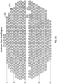
- Fig. 6A illustrates a tube sheet diagram of a condenser tube sheet.
- the condenser tubes are located in the condenser of the heat exchanger (see also Figs. 6C and 6D ).
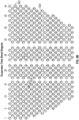
- the tube sheet diagram is a representation of the locations or positions of the heat exchanger tubes of the condenser, and may be represented in data in various formats so as to allow tracking of heat exchanger tubes through installation, testing, repair (e.g., plugging), replacement, etc.
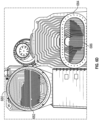
- Fig. 6D illustrates an end view of an example chiller (see Fig. 6C ), showing a condenser tube sheet 680 and an evaporator tube sheet 684, as suitable for embodiments.
- a suitable probe is inserted into an aperture 682 of the condenser tube sheet 680 or an aperture 686 of the evaporator tube sheet 684 and on into the selected heat exchanger tube that resides on the other side of the condenser tube sheet 680 or evaporator tube sheet 684, within the condenser or evaporator. There is thus no need to remove a heat exchanger tube from a heat exchanger, for such testing in accordance with embodiments.
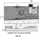
- Fig. 7A illustrates an example condenser tube 702 with no loss to tube wall.
- a damage region 704 shows bent, crushed or otherwise damaged fins on the exterior of the condenser tube 702, as may have occurred through physical contact or impact with an object.
- a cross-section longitudinal view shows the tube wall 708 has no loss in thickness, even in damage regions 710, 712 that have bent, crushed or even removed finning.
- Rendered test data 706 (see also Figs. 4A and 4B ) from probing the example condenser tube 702 is analyzed to determine the health assessment of the condenser tube 702, in various embodiments.
- signal data from a specific probe could be analyzed, through comparison with signal data from a probe of a calibration standard heat exchanger tube, to determine that there is no loss to the tube wall of this selected condenser tube 702, and the health assessment is that the condenser tube 702 has some damage but does not need repair or replacement.
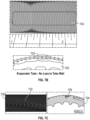
- signal data from a specific probe could be analyzed, through comparison with signal data from a probe of a calibration standard heat exchanger tube, to determine that there is loss of the tube wall in this selected condenser tube, and the health assessment is that the condenser tube has damage and does need repair or replacement.
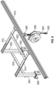
- Fig. 8 illustrates a tool fixture with a test probe 802, as suitable for various embodiments.
- a tool fixture may be an ergonomic fixture, which both positions the tool with test probe and relieves user fatigue that may occur from a user manually holding a tool.
- the tool fixture in this embodiment, has brackets or clamps 828, 832 that can be fastened to other fixed, movable or adjustable equipment, and has a sliding rail 810 to which a suitable tool 806 with a test probe 802 can be mounted.
- Vertical beams 824, 830 have the brackets or clamps 828, 832 and support horizontal beams 814, 812 that may be telescoping or slidable for adjustment.
- Crossbeams 818, 820 add support and rigidity to the tool fixture.
- the tool fixture allows for adjustment of X, Y, Z axis positioning of the tool 806 and support of the tool 806 while the probe 802 is inserted, and moved within a selected tube for testing.
- the tool fixture could be attached to a wheeled, variable height (e.g., electrical or hydraulic lift) dolly, platform or lift, which is then maneuvered into place, followed by manual adjustment of the tool fixture to align the tool 806 and probe 802, to a selected heat exchanger tube in situ (e.g. in a component, apparatus or on-site installation).
- a wheeled, variable height e.g., electrical or hydraulic lift
- dolly, platform or lift which is then maneuvered into place, followed by manual adjustment of the tool fixture to align the tool 806 and probe 802, to a selected heat exchanger tube in situ (e.g. in a component, apparatus or on-site installation).
- Fig. 9A illustrates a flow diagram for a method of non-destructive testing of heat exchanger tubing, in an embodiment.
- the method may be practiced using embodiments of equipment, components, systems and processes described herein, and variations thereof.
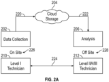
- Embodiments may use a calibration standard heat exchanger tube(s), may use cloud storage and/or may use remote analyst(s).
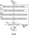
- test data is produced and stored, using a test probe in specific heat exchanger tube(s).
- the production of test data, and storage of same, do not need to be at the same location or at the same time.
- test data and calibration data, or processed data therefrom are accessed.
- the access may be through cloud storage.
- a structural health assessment of specific heat exchanger tube(s) is determined.
- the determination of structural health assessment may be by a remote analyst.
- the process includes using software, a processor, or other device to perform the health assessment.
- the health assessment may be displayed to on a screen (not shown).
- the display shows the various coils that pass or fail the assessment, potentially including a display similar to Figs. 6A and/or 6B.
- a structural health assessment is performed, using the secondary test data, or the secondary test data and the preliminary test data, for the specific heat exchanger tube(s). This may be accomplished using actions 902, 904, 906. Or this may be a variation of actions 902, 906.
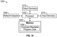
- Fig. 10 illustrates the control circuitry 1000, which may be an apparatus, according to some examples of the present disclosure.
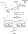
- the control circuitry 1000 includes some or all of the technical system 120, and/or the analysis system 130, or any other similar apparatus as described by the present disclosure.
- multiple components include control circuitry.
- the technician system 120 may comprise control circuitry 1000
- the analysis system 130 may comprise separate control circuitry 1000
- the cloud storage 138 may also include its own control circuitry.
- the control circuitry 1000 may include one or more of each of a number of components such as, for example, a processor 1002 connected to a memory 1004.
- the processor is generally any piece of computer hardware capable of processing information such as, for example, data, computer programs and/or other suitable electronic information.
- a method of non-destructive testing of heat exchanger tubing comprising: using a test probe inserted in a specific heat exchanger tube with machine-controlled testing, producing test data of non-destructive testing of the specific heat exchanger tube; accessing the test data of the non-destructive testing of the specific heat exchanger tube; and determining a structural health assessment of the specific heat exchanger tube using the accessed test data of the non-destructive testing of the specific heat exchanger tube in comparison to calibration data associated with at least one calibration standard heat exchanger tube that is more closely related to the specific heat exchanger tube than to a generic tube, in terms of its structural characteristics.
- the calibration standard heat exchanger tube may be made from the same material as the specific heat exchanger tube. The same material may be a same material alloy. The material alloy may be non-ferrous.
- the calibration standard heat exchanger tube may have one or more known defects.
- the calibration standard heat exchanger tube may have the same surface treatment as the specific heat exchanger tube.
- Clause 2 A method of any of the clauses listed herein, further comprising: using cloud-based storage for the test data of the non-destructive testing of the specific heat exchanger tube and the calibration data associated with the at least one calibration-standard heat exchanger tube, wherein accessing comprises accessing the cloud-based storage.
- test probe with machine-controlled testing comprises using robotics to position and operate a tool comprising the test probe.
- test probe with machine-controlled testing comprises using a machine-controlled pull-rate for the test probe.
- test probe comprises: using a tool mounted in an ergonomic fixture, the ergonomic fixture configured to relieve user fatigue and position the test probe; and the tool having a mechanized, controlled pull-rate for the test probe, for the machine-controlled testing.
- a method of any of the clauses listed herein, wherein using the test probe, producing the test data comprises: using a probe of a first probe type inserted in the specific heat exchanger tube to produce preliminary test data; and responsive to preliminary determination that the preliminary test data indicates possible defect in the specific heat exchanger tube, using a probe of a second, more sensitive probe type inserted in the specific heat exchanger tube to produce secondary test data.
- Clause 7 A method of any of the clauses listed herein, wherein producing the test data of the non-destructive testing of the specific heat exchanger tube and determining the structural health assessment of the specific heat exchanger tube are performed prior to delivery or installation of the specific heat exchanger tube.
- Clause 8 A method of any of the clauses listed herein, wherein: using the test probe, producing the test data of the non-destructive testing of the specific heat exchanger tube, is performed in situ where the specific heat exchanger tube is installed in a component at a first location or installed in a refrigerant system at a second location; and determining the structural health assessment of the specific heat exchanger tube is performed by a remote analyst, wherein the remote analyst is not on site where the specific heat exchanger tube is installed in the component or installed in the refrigerant system.
- Clause 9 A method of any of the clauses listed herein, further comprising: arranging a plurality of defects on at least one heat exchanger tube to form the at least one calibration standard heat exchanger tube; and with a same or related test probe inserted in the at least one calibration standard heat exchanger tube with same or related testing, producing the calibration data associated with the at least one calibration standard heat exchanger tube.
- a tangible, non-transitory, computer-readable media having instructions thereupon which, when executed by a processor, cause the processor to perform a method wherein test data and calibration data are being used for health assessment of heat exchanger tubes, the method comprising: receiving test data of non-destructive testing of a specific heat exchanger tube, produced using a test probe inserted in the specific heat exchanger tube with machine-controlled testing; storing, in a data storage, the test data of the non-destructive testing of the specific heat exchanger tube; receiving calibration data associated with at least one calibration standard heat exchanger tube that is more closely related to the specific heat exchanger tube than to a generic tube, in terms of its structural characteristics; storing the calibration data from the related non-destructive testing of the at least one calibration standard heat exchanger tube; and supporting accessing the test data of the non-destructive testing of the specific heat exchanger tube in the data storage and the calibration data from the testing of the at least one calibration standard heat exchanger tube, to enable a structural health assessment of the specific heat exchanger tube
- the calibration standard heat exchanger tube may be made from the same material as the specific heat exchanger tube.
- the same material may be a same material alloy.
- the material alloy may be non-ferrous.
- the calibration standard heat exchanger tube may have one or more known defects.
- the calibration standard heat exchanger tube may have the same surface treatment as the specific heat exchanger tube.
- Clause 12 The tangible, non-transitory, computer-readable media of any of the clauses listed herein, wherein the method further comprises: directing robotics to position and operate a tool comprising the test probe, for the machine-controlled testing.
- test data of the non-destructive testing of the specific heat exchanger tube comprises preliminary test data using a probe of a first probe type, and secondary test data using a probe of a second, more sensitive probe type.
- a system for non-destructive testing of heat exchanger tubing wherein the system is to provide test data and calibration data used in health assessment of heat exchanger tubes
- the system comprising: at least one memory; and at least one processor coupled to the at least one memory, and arranged to: receive test data of non-destructive testing of a specific heat exchanger tube produced using a test probe inserted in the specific heat exchanger tube; store the test data of the non-destructive testing of the specific heat exchanger tube in a data storage; store calibration data associated with at least one calibration standard heat exchanger tube that is more closely related to the specific heat exchanger tube than to a generic tube, in terms of its structural characteristics; and support accessing the test data of the non-destructive testing of the specific heat exchanger tube in the data storage and the calibration data from the testing of the at least one calibration standard heat exchanger tube, to enable a structural health assessment of the specific heat exchanger tube based on the test data and the calibration data.
- the calibration standard heat exchanger tube may be made from the same material as the specific heat exchanger tube.
- the same material may be a same material alloy.
- the material alloy may be non-ferrous.
- the calibration standard heat exchanger tube may have one or more known defects.
- the calibration standard heat exchanger tube may have the same surface treatment as the specific heat exchanger tube.
- Clause 16 The system for non-destructive testing of heat exchanger tubing of any of the clauses listed herein, wherein at least the data storage comprises cloud-based storage.
- Clause 17 The system for non-destructive testing of heat exchanger tubing of any of the clauses listed herein, further comprising: robotics to position and operate a tool comprising the test probe, for the machine-controlled testing.
- Clause 18 The system for non-destructive testing of heat exchanger tubing of any of the clauses listed herein, further comprising: a tool comprising at least one test probe and having a machine-controlled pull-rate for the at least one test probe.
- test data of the non-destructive testing of the specific heat exchanger tube comprises preliminary test data using a probe of a first probe type, and secondary test data using a probe of a second, more sensitive probe type.
- a method for non-destructive testing of heat exchanger tubing comprising: using a test probe inserted in a specific heat exchanger tube with machine-controlled testing, producing test data of non-destructive testing of the specific heat exchanger tube; accessing the test data of the non-destructive testing of the specific heat exchanger tube; and determining a structural health assessment of the specific heat exchanger tube using the accessed test data of the non-destructive testing of the specific heat exchanger tube in comparison to calibration data associated with at least one calibration standard heat exchanger tube.
- the calibration standard heat exchanger tube may be more closely related to the specific heat exchanger tube than to a generic tube, in terms of its structural characteristics.
- the calibration standard heat exchanger tube may be made from the same material as the specific heat exchanger tube. The same material may be a same material alloy. The material alloy may be non-ferrous.
- the calibration standard heat exchanger tube may have one or more known defects.
- the calibration standard heat exchanger tube may have the same surface treatment as the specific heat exchanger tube.
- Clause 26 The method of any one of the Clauses 21-25, wherein producing the test data of the non-destructive testing of the specific heat exchanger tube and determining the structural health assessment of the specific heat exchanger tube are performed prior to delivery or installation of the specific heat exchanger tube.
- Clause 27 The method of any one of Clauses 21-25, wherein: using the test probe and producing the test data of the non-destructive testing of the specific heat exchanger tube, is performed in situ where the specific heat exchanger tube is installed in a component at a first location or installed in a refrigerant system at a second location; and determining the structural health assessment of the specific heat exchanger tube is performed by a remote analyst, wherein the remote analyst is not on site at the location where the specific heat exchanger tube is installed in the component or installed in the refrigerant system.
- a module, an application, a layer, an agent or other method-operable entity could be implemented as hardware, firmware, or a processor executing software, or combinations thereof. It should be appreciated that, where a software-based embodiment is disclosed herein, the software can be embodied in a physical machine such as a controller. For example, a controller could include a first module and a second module. A controller could be configured to perform various actions, e.g., of a method, an application, a layer or an agent.
- the embodiments can also be embodied as computer readable code on a tangible non-transitory computer readable medium.
- the computer readable medium is any data storage device that can store data, which can be thereafter read by a computer system. Examples of the computer readable medium include hard drives, network attached storage (NAS), read-only memory, random-access memory, CD-ROMs, CD-Rs, CD-RWs, magnetic tapes, and other optical and non-optical data storage devices.
- the computer readable medium can also be distributed over a network coupled computer system so that the computer readable code is stored and executed in a distributed fashion.
- the units/circuits/components used with the "configured to” or “configurable to” language include hardware--for example, circuits, memory storing program instructions executable to implement the operation, etc. Reciting that a unit/circuit/component is “configured to” perform one or more tasks, or is “configurable to” perform one or more tasks, is expressly intended not to invoke 35 U.S.C. 112, sixth paragraph, for that unit/circuit/component. Additionally, "configured to" or “configurable to” can include generic structure (e.g., generic circuitry) that is manipulated by software and/or firmware (e.g., an FPGA or a general-purpose processor executing software) to operate in manner that is capable of performing the task(s) at issue.
- generic structure e.g., generic circuitry
- firmware e.g., an FPGA or a general-purpose processor executing software
- Configured to may also include adapting a manufacturing process (e.g., a semiconductor fabrication facility) to fabricate devices (e.g., integrated circuits) that are adapted to implement or perform one or more tasks.
- a manufacturing process e.g., a semiconductor fabrication facility
- devices e.g., integrated circuits
- Configurable to is expressly intended not to apply to blank media, an unprogrammed processor or unprogrammed generic computer, or an unprogrammed programmable logic device, programmable gate array, or other unprogrammed device, unless accompanied by programmed media that confers the ability to the unprogrammed device to be configured to perform the disclosed function(s).
Landscapes
- Chemical & Material Sciences (AREA)
- Physics & Mathematics (AREA)
- Engineering & Computer Science (AREA)
- General Health & Medical Sciences (AREA)
- Immunology (AREA)
- Life Sciences & Earth Sciences (AREA)
- Analytical Chemistry (AREA)
- Biochemistry (AREA)
- Electrochemistry (AREA)
- General Physics & Mathematics (AREA)
- Health & Medical Sciences (AREA)
- Pathology (AREA)
- Chemical Kinetics & Catalysis (AREA)
- Thermal Sciences (AREA)
- Mechanical Engineering (AREA)
- General Engineering & Computer Science (AREA)
- Investigating Or Analyzing Materials By The Use Of Magnetic Means (AREA)
Applications Claiming Priority (1)
| Application Number | Priority Date | Filing Date | Title |
|---|---|---|---|
| US18/399,048 US20250216165A1 (en) | 2023-12-28 | 2023-12-28 | Optimized cloud-based non-destructive testing on enhanced non-ferromagnetic heat exchanger tubing installed in fluid-cooled climate products |
Publications (1)
| Publication Number | Publication Date |
|---|---|
| EP4579232A1 true EP4579232A1 (de) | 2025-07-02 |
Family
ID=94129670
Family Applications (1)
| Application Number | Title | Priority Date | Filing Date |
|---|---|---|---|
| EP24223890.5A Pending EP4579232A1 (de) | 2023-12-28 | 2024-12-31 | Zerstörungsfreie prüfung auf verbesserten nicht ferromagnetischen wärmetauscherrohren in flüssigkeitsgekühlten klimaprodukten |
Country Status (3)
| Country | Link |
|---|---|
| US (1) | US20250216165A1 (de) |
| EP (1) | EP4579232A1 (de) |
| CN (1) | CN120232980A (de) |
Citations (4)
| Publication number | Priority date | Publication date | Assignee | Title |
|---|---|---|---|---|
| JPH0972501A (ja) * | 1995-09-08 | 1997-03-18 | Hitachi Ltd | 熱交換器細管探傷装置 |
| US20110125462A1 (en) * | 2009-05-14 | 2011-05-26 | Westinghouse Electric Company Llc | Tetherless tube inspection system |
| ES2676036B2 (es) * | 2017-01-13 | 2019-03-25 | Tecnatom S A | Sonda de corrientes inducidas digital con sistema de posicionamiento y metodo aplicado |
| US20230314373A9 (en) * | 2021-10-29 | 2023-10-05 | Eddyfi Canada Inc. | System and method for automated acquisition and analysis of electromagnetic testing data |
-
2023
- 2023-12-28 US US18/399,048 patent/US20250216165A1/en active Pending
-
2024
- 2024-12-30 CN CN202411969166.4A patent/CN120232980A/zh active Pending
- 2024-12-31 EP EP24223890.5A patent/EP4579232A1/de active Pending
Patent Citations (4)
| Publication number | Priority date | Publication date | Assignee | Title |
|---|---|---|---|---|
| JPH0972501A (ja) * | 1995-09-08 | 1997-03-18 | Hitachi Ltd | 熱交換器細管探傷装置 |
| US20110125462A1 (en) * | 2009-05-14 | 2011-05-26 | Westinghouse Electric Company Llc | Tetherless tube inspection system |
| ES2676036B2 (es) * | 2017-01-13 | 2019-03-25 | Tecnatom S A | Sonda de corrientes inducidas digital con sistema de posicionamiento y metodo aplicado |
| US20230314373A9 (en) * | 2021-10-29 | 2023-10-05 | Eddyfi Canada Inc. | System and method for automated acquisition and analysis of electromagnetic testing data |
Also Published As
| Publication number | Publication date |
|---|---|
| US20250216165A1 (en) | 2025-07-03 |
| CN120232980A (zh) | 2025-07-01 |
Similar Documents
| Publication | Publication Date | Title |
|---|---|---|
| US11346815B2 (en) | Predictive integrity analysis | |
| Rahman | Enhancing reliability in shell and tube heat exchangers: establishing plugging criteria for tube wall loss and estimating remaining useful life | |
| US6401000B1 (en) | Fraction defective estimating method and system for estimating an assembly fraction defective of an article | |
| US20180266992A1 (en) | Quantifying tubing defect severity | |
| Ahmed et al. | Condition monitoring in the management of maintenance in a large scale precision CNC machining manufacturing facility | |
| EP4579232A1 (de) | Zerstörungsfreie prüfung auf verbesserten nicht ferromagnetischen wärmetauscherrohren in flüssigkeitsgekühlten klimaprodukten | |
| US8483993B2 (en) | Accurately accounting for sizing uncertainty in inspection | |
| WO2019159940A1 (ja) | プラントの検査方法 | |
| JP7667259B2 (ja) | 自動検査計画に基づく検出 | |
| US11965619B2 (en) | Heat exchanger tube plug installation | |
| US12467905B2 (en) | In-line inspection and crack detection | |
| JP7646039B2 (ja) | 亀裂検査装置、亀裂検査システム、および亀裂検査方法 | |
| US6526326B2 (en) | Fraction defective estimating method and system for estimating an assembly fraction defective of an article | |
| RU2857480C1 (ru) | Способ мониторинга технического состояния и безопасности опасных производственных объектов на стадиях жизненного цикла | |
| CN118501246B (zh) | 一种基于耐高温检测器的大变形管道缺陷检测方法及系统 | |
| Okoloekwe et al. | Algorithms for the strain based analysis of dented pipelines | |
| Magesh | Effect of Single and Multistage Mandrel Forming on U-Shaped, Thin-Walled Metal Ellows-Type Expansion Joints | |
| CN121195165A (zh) | 用于工业检查的多感测方法 | |
| Hoeve et al. | Tools for Analysing Large Numbers of Inspection Data, Used to Asses Remnant Life of Pipework | |
| Fraser et al. | Pipeline Corrosion and Mechanical Damage Analysis Using a 3D Laser Scanner | |
| Aidibe et al. | A robust iterative displacement inspection algorithm for quality control of aerospace non-rigid parts without conformation jig | |
| Thielager et al. | Applying ultrasonic in-line inspection technology in a deep water environment: exploring the challenges | |
| Alin | COMPARATIVE STUDY OF DEEP DRAWING PARTS MEASUREMENT METHODS |
Legal Events
| Date | Code | Title | Description |
|---|---|---|---|
| PUAI | Public reference made under article 153(3) epc to a published international application that has entered the european phase |
Free format text: ORIGINAL CODE: 0009012 |
|
| STAA | Information on the status of an ep patent application or granted ep patent |
Free format text: STATUS: THE APPLICATION HAS BEEN PUBLISHED |
|
| AK | Designated contracting states |
Kind code of ref document: A1 Designated state(s): AL AT BE BG CH CY CZ DE DK EE ES FI FR GB GR HR HU IE IS IT LI LT LU LV MC ME MK MT NL NO PL PT RO RS SE SI SK SM TR |
|
| STAA | Information on the status of an ep patent application or granted ep patent |
Free format text: STATUS: REQUEST FOR EXAMINATION WAS MADE |
|
| 17P | Request for examination filed |
Effective date: 20251230 |