EP4579104A1 - Vehicular drive device - Google Patents
Vehicular drive device Download PDFInfo
- Publication number
- EP4579104A1 EP4579104A1 EP23897832.4A EP23897832A EP4579104A1 EP 4579104 A1 EP4579104 A1 EP 4579104A1 EP 23897832 A EP23897832 A EP 23897832A EP 4579104 A1 EP4579104 A1 EP 4579104A1
- Authority
- EP
- European Patent Office
- Prior art keywords
- case
- axial direction
- housing chamber
- breather
- electrical machine
- Prior art date
- Legal status (The legal status is an assumption and is not a legal conclusion. Google has not performed a legal analysis and makes no representation as to the accuracy of the status listed.)
- Pending
Links
Images







Classifications
-
- H—ELECTRICITY
- H02—GENERATION; CONVERSION OR DISTRIBUTION OF ELECTRIC POWER
- H02K—DYNAMO-ELECTRIC MACHINES
- H02K5/00—Casings; Enclosures; Supports
- H02K5/04—Casings or enclosures characterised by the shape, form or construction thereof
- H02K5/10—Casings or enclosures characterised by the shape, form or construction thereof with arrangements for protection from ingress, e.g. water or fingers
-
- F—MECHANICAL ENGINEERING; LIGHTING; HEATING; WEAPONS; BLASTING
- F16—ENGINEERING ELEMENTS AND UNITS; GENERAL MEASURES FOR PRODUCING AND MAINTAINING EFFECTIVE FUNCTIONING OF MACHINES OR INSTALLATIONS; THERMAL INSULATION IN GENERAL
- F16H—GEARING
- F16H57/00—General details of gearing
- F16H57/02—Gearboxes; Mounting gearing therein
- F16H57/027—Gearboxes; Mounting gearing therein characterised by means for venting gearboxes, e.g. air breathers
-
- F—MECHANICAL ENGINEERING; LIGHTING; HEATING; WEAPONS; BLASTING
- F16—ENGINEERING ELEMENTS AND UNITS; GENERAL MEASURES FOR PRODUCING AND MAINTAINING EFFECTIVE FUNCTIONING OF MACHINES OR INSTALLATIONS; THERMAL INSULATION IN GENERAL
- F16H—GEARING
- F16H57/00—General details of gearing
- F16H57/04—Features relating to lubrication or cooling or heating
-
- F—MECHANICAL ENGINEERING; LIGHTING; HEATING; WEAPONS; BLASTING
- F16—ENGINEERING ELEMENTS AND UNITS; GENERAL MEASURES FOR PRODUCING AND MAINTAINING EFFECTIVE FUNCTIONING OF MACHINES OR INSTALLATIONS; THERMAL INSULATION IN GENERAL
- F16H—GEARING
- F16H57/00—General details of gearing
- F16H57/02—Gearboxes; Mounting gearing therein
- F16H2057/02034—Gearboxes combined or connected with electric machines
-
- H—ELECTRICITY
- H02—GENERATION; CONVERSION OR DISTRIBUTION OF ELECTRIC POWER
- H02K—DYNAMO-ELECTRIC MACHINES
- H02K11/00—Structural association of dynamo-electric machines with electric components or with devices for shielding, monitoring or protection
- H02K11/20—Structural association of dynamo-electric machines with electric components or with devices for shielding, monitoring or protection for measuring, monitoring, testing, protecting or switching
- H02K11/21—Devices for sensing speed or position, or actuated thereby
-
- H—ELECTRICITY
- H02—GENERATION; CONVERSION OR DISTRIBUTION OF ELECTRIC POWER
- H02K—DYNAMO-ELECTRIC MACHINES
- H02K2205/00—Specific aspects not provided for in the other groups of this subclass relating to casings, enclosures, supports
- H02K2205/09—Machines characterised by drain passages or by venting, breathing or pressure compensating means
-
- H—ELECTRICITY
- H02—GENERATION; CONVERSION OR DISTRIBUTION OF ELECTRIC POWER
- H02K—DYNAMO-ELECTRIC MACHINES
- H02K7/00—Arrangements for handling mechanical energy structurally associated with dynamo-electric machines, e.g. structural association with mechanical driving motors or auxiliary dynamo-electric machines
- H02K7/10—Structural association with clutches, brakes, gears, pulleys or mechanical starters
- H02K7/116—Structural association with clutches, brakes, gears, pulleys or mechanical starters with gears
Definitions
- the present disclosure relates to a vehicular drive device.
- a technique is known in which, in a vehicular drive device, a breather chamber communicated with an outside of a case is partitioned to a motor housing chamber of the case.
- a breather recess (breather chamber) is closed by a flat breather plate, and in a case where capacity of the breather chamber is increased, the case may be increased in size along with an increase in size of the breather recess.
- the present disclosure intends to efficiently secure a necessary capacity of a breather chamber while preventing an increase in size of a case.
- a vehicular drive device includes
- a Y direction correspond to an up-down direction in a state where a vehicular drive device 100 is in use, that is, an up-down direction with respect to an orientation in which the vehicular drive device 100 in use is disposed.
- a Y1 side and a Y2 side correspond to an upper side and a lower side along the Y direction.
- the up-down direction is not necessarily parallel to a vertical direction, and it is only required that a vertical direction component is predominant.
- orientations of respective members in the following description represent orientations in a state where the respective members are fitted to the vehicular drive device 100.
- an A direction corresponds to an axial direction
- an A1 side and an A2 side along the A direction are defined in FIG. 2 and the like.
- an X direction is a direction orthogonal to both the A direction and the Y direction, and an X1 side and an X2 side along the X direction are defined in FIG. 3 and the like.
- “communication” refers to a state in which two spatial elements in fluid communication with each other. That is, “communication” refers to a state in which fluid can move back and forth between the two spatial elements. In this case, the two spatial elements may communicate directly or indirectly (that is, via another spatial element).
- the "rotating electrical machine” is used as a concept including any of a motor (electric motor), a generator (generator), and a motor-generator that functions as both the motor and the generator as necessary.
- "to overlap as viewed in a specific direction” means that, in a case where a virtual straight line parallel to the direction of a line of sight is moved in each direction orthogonal to the virtual straight line, a region where the virtual straight line intersects both of the two members exists in at least a part.
- “disposition regions in a specific direction overlap” means that at least a part of a disposition region in a specific direction of one member is included in a disposition region in a specific direction of another member.
- FIG. 1 is a schematic top view showing a state of the vehicular drive device 100 mounted on a vehicle VC.
- FIG. 2 is a cross-sectional view of the vehicular drive device 100.
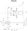
- FIG. 2A is a skeleton diagram showing the vehicular drive device 100.
- the vehicular drive device 100 includes a rotating electrical machine 1, a pair of output members 6 drivingly coupled to a pair of wheels W (refer to FIG. 1 ), and a transmission mechanism 3 that transmits drive force between the rotating electrical machine 1 and the pair of output members 6.
- the vehicular drive device 100 further includes a case 2 that houses the rotating electrical machine 1.
- the case 2 also houses the pair of output members 6 and the transmission mechanism 3. Note that, in a modification, the case 2 may house only one (a first output member 61, for example) of the pair of output members 6.
- a drive source may be only an engine (internal combustion engine).
- a first output member 61 which is one of the pair of output members 6, is drivingly coupled to a first wheel W1, which is one of the pair of wheels W.
- a second output member 62 which is another one of the pair of output members 6, is drivingly coupled to a second wheel W2, which is another one of the pair of wheels W.
- the vehicle VC on which the vehicular drive device 100 is mounted includes a first drive shaft 63 that rotates integrally with the first wheel W1 and a second drive shaft 64 that rotates integrally with the second wheel W2.
- the first drive shaft 63 is coupled to the first wheel W1 via, for example, a constant-velocity joint
- the second drive shaft 64 is coupled to the second wheel W2 via, for example, a constant-velocity joint.
- the first output member 61 is coupled to the first drive shaft 63 so as to rotate integrally with the first drive shaft 63
- the second output member 62 is coupled to the second drive shaft 64 so as to rotate integrally with the second drive shaft 64.
- the first output member 61 may be in a form of an intermediate shaft.
- the first output member 61 is rotatably supported with respect to the case 2 via a bearing BR1 on an axial direction second side A2, and is rotatably supported with respect to the case 2 via a bearing BR2 on an axial direction first side A1.
- the bearings BR1 and BR2 are in a form of ball bearing.
- the bearings BR1 and BR2 may be in another form.
- the vehicular drive device 100 transmits output torque of the rotating electrical machine 1 to the pair of wheels W via the pair of output members 6 to cause the vehicle VC equipped with the vehicular drive device 100 to travel. That is, the rotating electrical machine 1 is a drive force of the pair of wheels W.
- the pair of wheels W is a pair of left and right wheels (for example, a pair of left and right front wheels or a pair of left and right rear wheels) in the vehicle VC.
- the rotating electrical machine 1 may be, for example, an alternating-current rotating electrical machine driven by three-phase alternating current power.
- the rotating electrical machine 1 and the pair of output members 6 are disposed separately on two axes (specifically, a first axis C1 and a second axis C2) parallel to each other.
- the rotating electrical machine 1 is disposed on the first axis C1
- the pair of output members 6 is disposed on the second axis C2 different from the first axis C1.
- the first axis C1 and the second axis C2 are axes (virtual axes) arranged parallel to each other.
- the transmission mechanism 3 includes an output gear (ring gear) 30 drivingly coupled to at least one of the pair of output members 6, coaxially with the pair of output members 6 (that is, on the second axis C2).
- the rotating electrical machine 1 is, for example, inner rotor type.
- a rotor 14 that is rotatable about the first axis C1 is disposed radially inner side of a stator 11 (refer to FIG. 2 ).
- the rotor shaft 15 of the rotor 14 is rotatably supported with respect to the case 2 via a bearing BR3 on an axial direction second side A2, and is rotatably supported with respect to the case 2 via a bearing BR4 on an axial direction first side A1.
- the bearings BR3 and BR4 are in a form of ball bearing.
- the bearings BR1 and BR2 may be in another form. Note that, in the example shown in FIG.
- the rotor shaft 15 has the shaft center oil passage 15a and an ejection vent 15b in a radial direction, and, during rotation, can eject oil in a shaft center oil passage 15a from each ejection vent 15b in the radial direction toward a coil end 13 by centrifugal force.
- the transmission mechanism 3 includes a deceleration mechanism 34 in a power transmission path between the rotating electrical machine 1 and an output gear 30.
- the deceleration mechanism 34 is arbitrary, and may include a deceleration mechanism using a counter gear, a deceleration mechanism using a planetary gear, and the like.
- the deceleration mechanism 34 includes a planetary gear mechanism, and the deceleration mechanism 34 is disposed coaxially with the rotating electrical machine 1.
- An output gear (carrier) 342 of the deceleration mechanism 34 meshes with the output gear 30 of a differential gear mechanism 5 in a radial direction.
- Such a vehicular drive device 100 can have a compact configuration including two axes (the first axis C1 and the second axis C2). Note that, in a modification, the vehicular drive device 100 may have three or more axes.
- the deceleration mechanism 34 is disposed coaxially with the rotating electrical machine 1 (that is, on the first axis C1) in such a manner as to be drivingly coupled to the rotating electrical machine 1.
- the rotor 14 of the rotating electrical machine 1 rotates integrally with an input member 16 together with a sun gear 341 of the deceleration mechanism 34.
- the transmission mechanism 3 further includes the differential gear mechanism 5.
- the differential gear mechanism 5 distributes the drive force transmitted from a rotating electrical machine 1 side to the pair of output members 6.
- the differential gear mechanism 5 distributes rotation of the output gear 30 to a first side gear 51 and a second side gear 52.
- the differential gear mechanism 5 may be disposed coaxially with the pair of output members 6 (that is, on the second axis C2).
- the differential gear mechanism 5 may be a bevel-gear type differential gear mechanism, and the output gear 30 may be coupled to a differential case part 50 so as to rotate integrally with the differential case part 50 included in the differential gear mechanism 5.
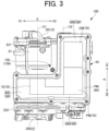
- FIG. 3 is a top view schematically showing the vehicular drive device 100 according to the present embodiment.
- an inverter cover member 203 on an upper portion of an inverter case part 24 is not shown so that elements disposed inside the inverter case part 24 can be seen.
- the case 2 includes a motor case part 21, a transmission mechanism case part 22, an output shaft case part 23, and an inverter case part 24 in an integrated form.
- the "integrated form” includes an integrated form using a fastening member such as a bolt and an integrated form utilizing integral molding (for example, casting or pouring utilizing aluminizing or the like).
- the motor case part 21 forms the motor housing chamber S1 that houses the rotating electrical machine 1
- the transmission mechanism case part 22 forms a transmission mechanism housing chamber S2 that houses the transmission mechanism 3
- the output shaft case part 23 forms the output shaft housing chamber S3 that houses the first output member 61
- the inverter case part 24 forms an inverter housing chamber S4 that houses the inverter device 70.
- the motor case part 21 forming the motor housing chamber S1 means that a wall part that bounds the motor housing chamber S1 forms the motor case part 21.
- the motor case part 21 has a cylindrical shape corresponding to an outer shape of the rotating electrical machine 1. However, an entire cylindrical outer peripheral part of the motor case part 21 is not necessarily closed.
- the motor housing chamber S1 and the output shaft housing chamber S3 may communicate with each other, and in this case, a wall part (partition wall part) may not be formed on a side of the motor case part 21, the side facing the output shaft housing chamber S3.
- the transmission mechanism case part 22 is provided on the axial direction second side A2 with respect to the motor case part 21 and the output shaft case part 23.
- the output shaft case part 23 is provided on the X2 side in the X direction with respect to the motor case part 21.
- the inverter case part 24 is provided on the upper side of the transmission mechanism case part 22 and the output shaft case part 23. Details of the inverter case part 24 will be described later.
- the output shaft case part 23 is provided. Therefore, the first output member 61 can be effectively protected from an external environment (for example, a splashing stone or the like) as compared with a case where the first output member 61 is provided outside the case 2. Furthermore, clearance to be secured between the first output member 61 and peripheral components can be reduced. However, in a modification, the first output member 61 may be provided outside the case 2.
- the case 2 is formed by joining a case member 200, the motor cover member 201, a differential cover member 202, and an inverter cover member 203.
- a joining method may be fastening with bolts or the like.
- the inverter case part 24 is disposed so as to overlap the first axis C1 and the second axis C2 as viewed from top (viewed in a second direction Y, hereinafter the same).
- the inverter housing chamber S4 extends on both sides of the A direction with respect to the center in the A direction in a manner of extending across the center in the A direction.
- the inverter housing chamber S4 extends only on the axial direction second side A2 of the center in the A direction.
- the first housing part S41, the second housing part S42, and the third housing part S43 are disposed above a plane (not shown) including the first axis C1 that is an axial center of a rotary shaft of the rotating electrical machine 1 and the second axis C2 that is an axial center of the output members 6.
- a plane (not shown) including the first axis C1 and the second axis C2 is a plane close to a horizontal plane.
- first housing part S41, the second housing part S42, and the third housing part S43 do not need to be specific, and for example, a portion of the power module PM in the axial direction first side A1 may be disposed in the second housing part S42, and a portion of the power module PM in the first direction first side X1 may be disposed in the first housing part S41.
- FIG. 3A is a side view from the axial direction first side A1, schematically showing the vehicular drive device according to the present embodiment.
- the motor cover member 201 is not shown so that a state of an inside of the motor housing chamber S1 can be seen.
- an inverter device 70 inside an inverter case part 24 is schematically shown by a dotted line.
- FIG. 4 is a perspective view of the channel forming member 90.
- the water-cooling structure of the rotating electrical machine 1 is a structure for cooling the rotating electrical machine 1 with cooling water.
- the cooling water may be, for example, water containing long life coolant: LLC, and may be circulated by a water pump (not shown).
- a heat radiation unit such as a radiator (not shown) may be provided in the circulation path of the cooling water.
- the cooling water may be utilized not only for cooling the rotating electrical machine 1 but also for cooling another component, for example, the inverter device 70 or the like electrically connected to the rotating electrical machine 1.
- the water-cooling structure of the rotating electrical machine 1 includes a refrigerant supply unit 40, a refrigerant discharge unit 42, and a channel forming member 90.
- the refrigerant supply unit 40 communicates with, for example, a discharge side of the water pump (not shown), and supplies the cooling water to the refrigerant channel 300 formed by the channel forming member 90.
- the refrigerant discharge unit 42 communicates with, for example, a suction side of the water pump (not shown), and supplies (discharges) the cooling water from the refrigerant channel 300 formed by the channel forming member 90 to the water pump (not shown).
- the refrigerant supply unit 40 and the refrigerant discharge unit 42 may be provided on upper and lower sides with the first output member 61 interposed therebetween. In this case, the refrigerant supply unit 40 and the refrigerant discharge unit 42 can be established by effectively utilizing space around the first output member 61.
- the channel forming member 90 has a cylindrical shape having an inner peripheral surface radially facing an outer peripheral surface of the rotating electrical machine 1.
- the channel forming member 90 forms the refrigerant channel 300 around the rotating electrical machine 1.
- the refrigerant channel 300 has a plurality of channel parts SC1 to SC4 in a circumferential direction, but the refrigerant channel 300 can be arbitrarily configured.
- the channel forming member 90 may be formed of a material having good thermal conductivity, such as aluminum, for example
- the channel forming member 90 is fitted to a stator core 12 of the stator 11 by shrink-fitting, for example.
- the channel forming member 90 may be integrally formed with the stator core 12 by casting or the like.
- the channel forming member 90 is in a form of the inner case fastened to the case 2.
- an axially one end side of the channel forming member 90 may have a plurality of fastening parts 500 as shown in FIG. 3A .
- the plurality of fastening parts 500 are fastened to the case 2 by bolts (not shown) (refer to bolt holes BT4).
- the channel forming member 90 may be formed as a part of the case 2.
- the channel forming member 90 is inserted into a space having a columnar shape in the case 2. At this time, an outer peripheral surface of the channel forming member 90 radially faces an inner peripheral surface (inner peripheral surface that bounds the plurality of fastening parts 500) of the case 2.
- an inner peripheral surface of the case 2 surrounding the channel forming member 90 in this manner is also referred to as a "channel forming surface 209 of the case 2" (refer to FIG. 5 ).
- an inner diameter of the channel forming surface 209 of the case 2 may be a constant value larger by a base thickness of the channel forming member 90 than a base outer diameter of the stator core 12.
- the transmission mechanism housing chamber S2 and the output shaft housing chamber S3 overlap the second axis C2 as viewed from top and are adjacent to each other in the axial direction. Furthermore, because the transmission mechanism housing chamber S2 extends in the X direction in such a manner as to house the deceleration mechanism 34 and the differential gear mechanism 5, the transmission mechanism housing chamber S2 and the output shaft housing chamber S3 extend in an L shape as viewed from top.
- a part housing the deceleration mechanism 34 is also referred to as a "deceleration mechanism housing chamber S21”
- a part housing the differential gear mechanism 5 is also referred to as a "differential gear housing chamber S22".
- the output shaft case part 23 extends around the second axis C2 along an extending direction (that is, the axial direction) of the first output member 61.
- the output shaft case part 23 may be in a form of a peripheral wall part that forms a space (the output shaft housing chamber S3) around the first output member 61. Note that, in this case, the output shaft case part 23 may extend radially outer side (X direction X2 side) of the rotating electrical machine 1, and may also form a part of the motor case part 21.
- a lubrication system is adopted in which various objects to be lubricated are scraped up by rotation of the output gear 30 (so-called a differential ring) of the differential gear mechanism 5.
- the return channel 290 is opened at a lower portion (below the second axis C2) of the differential gear housing chamber S22 of the transmission mechanism housing chamber S2.
- the end portion on the axial direction second side A2 of the return channel 290 (opening on a differential gear housing chamber S22 side) preferably overlaps the output gear 30 as viewed in the axial direction.
- the oil returned to the transmission mechanism housing chamber S2 in this manner is returned to the differential gear housing chamber S22 from the discharge port 922 below the second axis C2 in the catch tank 920.
- the rotation of the output gear 30 of the differential gear mechanism 5 can scrape up the oil again.
- the third opening 156 is disposed near a central portion of the case 2 as viewed in the up-down direction. Specifically, the third opening 156 is disposed between the first axis C1 and the second axis C2 in the first direction X (an example of a direction perpendicular to a first axis) and between a center position of the rotating electrical machine 1 and a center position of the deceleration mechanism 34 in the axial direction A (an example of a direction parallel to the first axis). Note that the center position of the rotating electrical machine 1 in the axial direction A may correspond to, for example, a center position of the stator core 12 in the axial direction.
- the breather 150 According to such a disposition of the breather 150, it is possible to easily establish the breather 150 by utilizing a dead space which easily formed, between the rotating electrical machine 1 and the deceleration mechanism 34 and between the first axis C1 and the second axis C2, in the axial direction A.
- the third opening 156 of the breather 150 can be disposed near the central portion of the case 2 as viewed in the up-down direction, while reducing a size of the vehicular drive device 100 in the up-down direction.
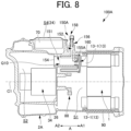
- FIG. 8 is a schematic cross-sectional view of a vehicular drive device 100A, taken along a vertical plane passing through a breather 150A according to the present second embodiment.
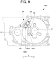
- FIG. 9 is a side view from the axial direction first side A1, schematically showing a partition wall 26 in the vehicular drive device 100A according to the present second embodiment.
- a part of the configuration (the rotating electrical machine 1 and the like) in the motor housing chamber S1 is not shown for ease of viewing.
- a part (lid part 169) of an insulating member 160 described later is not shown for ease of viewing.
- the breather 150A is different from the breather 150 according to the above-described first embodiment in a configuration on a motor housing chamber S1 side.
- the breather 150A has an opening 155A on the motor housing chamber S1 side formed by a case 2A, instead of the first opening 153 of the breather 150 according to the first embodiment described above. Unlike the breather 150 according to the first embodiment described above, the breather 150A is opened to the motor housing chamber S1 via the insulating member 160 that is a member different from the case 2A described later.
- the insulating member 160 is formed by an insulating material (for example, a resin material) having an electrical insulating property, and forms an insulating part of breather 150A. That is, the breather 150A includes an insulating part formed by the insulating member 160 in addition to a conductor portion formed by the case 2A.
- an insulating material for example, a resin material
- the rotation angle sensor 88 is in a form of, for example, a resolver, but may be in another form.
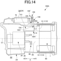
- FIG. 14 is a schematic cross-sectional view of a vehicular drive device 100A according to the comparative example, taken along a vertical plane passing through a breather 150'.
- a breather 150' according to the comparative example is different from the breather 150A according to the present second embodiment in that the insulating member 160 is replaced with a lid member 28' made of metal.
- the lid member 28' is formed of, for example, a material (for example, aluminum) similar to the case 2A.
- the lid member 28' is in a form of a flat plate and covers the opening 155A on the axial direction first side A1 in the first passage 151. Note that the lid member 28' may form the drain hole 1641' and the vent hole 1631'.
- the first passage 151 faces the coil end 13-1 as viewed in the axial direction A. Therefore, if the first passage 151 is extended to the axial direction first side A1, an electrical insulation distance between the coil end 13-1 and an end portion on the axial direction first side A1 in the case 2A (specifically, an outer peripheral edge portion around the first passage 151) is shortened. Therefore, due to necessity (restriction) of securing a necessary electrical insulation distance between the coil end 13-1 and the end portion on the axial direction first side A1 of the case 2A, it is difficult to increase the capacity of the breather chamber by extending the first passage 151 to the axial direction first side A1.
- the lid member 28' is a conductor axially facing the coil end 13-1. Therefore, the lid member 28' is disposed away from the coil end 13-1 by a necessary electrical insulation distance L14 (refer to FIG. 14 ) or more.
- the insulating member 160 described above is provided so as to cover a portion 29 (a portion of the partition wall 26) around the first passage 151 in the case 2A.
- the insulating member 160 is positioned between the portion 29 around the first passage 151 in the case 2A and the coil end 13-1.
- the above-described insulating member 160 can be brought close to the coil end 13-1 while facing the coil end 13-1 in the axial direction.
- the second opening 154 may be omitted. That is, the breather 150A may not be opened to the transmission mechanism housing chamber S2.
- the third opening 156 similar to the third opening 156 in the first embodiment described above is provided.
- an opening (vent opening opened to the atmosphere) corresponding to the third opening 156 may be provided at a position different from a position of the third opening 156 in the first embodiment described above.
- the ventilation hollow projection part 1630 and the drain hollow projection part 1640 are provided in the second embodiment.
- either one or both of the ventilation hollow projection part 1630 and the drain hollow projection part 1640 may be omitted in the present second embodiment.
- a vent hole may be provided on an upper side of the lid part 169.
- the vent hole 1631 of the breather 150A is opened to the motor housing chamber S1.
- the vent hole 1631 may be provided to be opened to the transmission mechanism housing chamber S2.
- the ventilation hollow projection part 1630 may be omitted, or a similar ventilation hollow projection part, which is different only in not having the vent hole 1631, may be provided. Even in the latter case, necessary capacity of the breather chamber of the breather 150A can still be efficiently secured.
- the drain hole 1641 of the breather 150A is opened to the motor housing chamber S1.
- the drain hole 1641 may be provided to be opened to the transmission mechanism housing chamber S2.
- the drain hollow projection part 1640 may be omitted, or a similar drain hollow projection part, which is different only in not having the drain hole 1641, may be provided. Even in the latter case, necessary capacity of the breather chamber of the breather 150A can still be efficiently secured.
- the rotating electrical machine 1 and the transmission mechanism 3 are provided, but either one may be omitted.
- an insulating member corresponding to the insulating member 160 may be provided on a second opening 154 side.
- the invention according to the following supplementary note intends to eliminate or reduce an increase in size of a vehicular drive device caused by a breather.
- a vehicular drive device including
Landscapes
- Engineering & Computer Science (AREA)
- General Engineering & Computer Science (AREA)
- Mechanical Engineering (AREA)
- Power Engineering (AREA)
- Hybrid Electric Vehicles (AREA)
Abstract
Description
- The present disclosure relates to a vehicular drive device.
- A technique is known in which, in a vehicular drive device, a breather chamber communicated with an outside of a case is partitioned to a motor housing chamber of the case.
- Patent Literature 1:
JP 2021-170906 A - However, in the conventional technique as described above, a breather recess (breather chamber) is closed by a flat breather plate, and in a case where capacity of the breather chamber is increased, the case may be increased in size along with an increase in size of the breather recess.
- Accordingly, in one aspect, the present disclosure intends to efficiently secure a necessary capacity of a breather chamber while preventing an increase in size of a case.
- In one aspect, a vehicular drive device includes
- a transmission mechanism that transmits drive force from a drive source to a wheel;
- a case that forms a housing chamber that houses at least either the drive source or the transmission mechanism along with oil; and
- a breather provided on the case, in which
- the breather includes
- a case-side opening opened to the housing chamber,
- a vent opening opened to atmosphere, and
- a breather chamber that communicates with the case-side opening and the vent opening,
- the breather chamber includes
- a first breather chamber formed in the case, and
- a second breather chamber formed by an insulating member attached to the case.
- In one aspect, according to the present disclosure, it is possible to efficiently secure necessary capacity of the breather chamber while preventing an increase in size of a case.
-
-
FIG. 1 is a schematic top view showing a state of a vehicular drive device mounted on a vehicle. -
FIG. 2 is a cross-sectional view of the vehicular drive device. -
FIG. 2A is a skeleton diagram illustrating the vehicular drive device. -
FIG. 3 is a top view schematically showing a vehicular drive device according to a first embodiment. -
FIG. 3A is a side view from an axial direction first side A1, schematically showing the vehicular drive device according to the first embodiment. -
FIG. 4 is a perspective view of a channel forming member. -
FIG. 5 is an enlarged view of a portion Q6 inFIG. 2 . -
FIG. 6 is a side view from an axial direction second side A2, schematically showing the vehicular drive device according to the first embodiment. -
FIG. 7 is a schematic cross-sectional view of the vehicular drive device, taken along a vertical plane passing through a breather according to the first embodiment. -
FIG. 8 is a schematic cross-sectional view of a vehicular drive device, taken along a vertical plane passing through a breather according to a second embodiment. -
FIG. 9 is a side view from an axial direction first side A1, schematically showing a partition wall in the vehicular drive device according to the second embodiment. -
FIG. 10 is an enlarged view of a portion Q10 inFIG. 8 . -
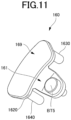
FIG. 11 is a perspective view of a state of an insulating member as a single part, as viewed from the axial direction first side A1. -
FIG. 12 is an exploded perspective view of the insulating member inFIG. 11 . -
FIG. 13 is a perspective view of a state of the insulating member as a single part, as viewed from the axial direction second side A2. -
FIG. 14 is a schematic cross-sectional view of a vehicular drive device, taken along a vertical plane passing through a breather according to a comparative example. - Hereinafter, each embodiment will be described in detail with reference to the accompanying drawings. Note that the dimension ratios in the drawings are merely examples, and the dimensional ratios are not limited thereto, and shapes and the like in the drawings may be partially exaggerated for convenience of description. Furthermore, in the drawings, only some of a plurality of parts having the same attribute may be denoted by reference signs for the sake of clarity.
- In the following description, a Y direction (refer to
FIG. 3A and the like) correspond to an up-down direction in a state where avehicular drive device 100 is in use, that is, an up-down direction with respect to an orientation in which thevehicular drive device 100 in use is disposed. Then, a Y1 side and a Y2 side correspond to an upper side and a lower side along the Y direction. Note that the up-down direction is not necessarily parallel to a vertical direction, and it is only required that a vertical direction component is predominant. Furthermore, orientations of respective members in the following description represent orientations in a state where the respective members are fitted to thevehicular drive device 100. Furthermore, terms related to dimensions, disposition orientation, disposition position, and the like of each member are concepts including a state of those having a difference due to an error (an allowable error in manufacturing). An A direction (refer toFIG. 2 and the like) corresponds to an axial direction, and an A1 side and an A2 side along the A direction are defined inFIG. 2 and the like. Furthermore, an X direction (refer toFIG. 3 and the like) is a direction orthogonal to both the A direction and the Y direction, and an X1 side and an X2 side along the X direction are defined inFIG. 3 and the like. - In the present specification, "drivingly coupled" state refers to a state in which two rotational elements are coupled so as to be able to transmit drive force (synonymous with torque), and includes a state in which the two rotational elements are coupled so as to rotate integrally, or a state in which the two rotational elements are coupled so as to be able to transmit drive force via one or more transmission members. Such a transmission member includes various members (for example, a shaft, a gear mechanism, a belt, a chain, and the like) that transmit rotation at the same speed or at a different speed. Note that an engagement device (for example, a friction engagement device, a meshing engagement device, or the like) that selectively transmits rotation and drive force may be included as the transmission member.
- Furthermore, in the present specification, "communication" refers to a state in which two spatial elements in fluid communication with each other. That is, "communication" refers to a state in which fluid can move back and forth between the two spatial elements. In this case, the two spatial elements may communicate directly or indirectly (that is, via another spatial element).
- In the present specification, the "rotating electrical machine" is used as a concept including any of a motor (electric motor), a generator (generator), and a motor-generator that functions as both the motor and the generator as necessary. Furthermore, in the present specification, with respect to arrangement of two members, "to overlap as viewed in a specific direction" means that, in a case where a virtual straight line parallel to the direction of a line of sight is moved in each direction orthogonal to the virtual straight line, a region where the virtual straight line intersects both of the two members exists in at least a part. Furthermore, in the present specification, with respect to arrangement of two members, "disposition regions in a specific direction overlap" means that at least a part of a disposition region in a specific direction of one member is included in a disposition region in a specific direction of another member.
-
FIG. 1 is a schematic top view showing a state of thevehicular drive device 100 mounted on a vehicle VC.FIG. 2 is a cross-sectional view of thevehicular drive device 100.FIG. 2A is a skeleton diagram showing thevehicular drive device 100. - As schematically shown in
FIG. 2A , thevehicular drive device 100 includes a rotatingelectrical machine 1, a pair ofoutput members 6 drivingly coupled to a pair of wheels W (refer toFIG. 1 ), and atransmission mechanism 3 that transmits drive force between the rotatingelectrical machine 1 and the pair ofoutput members 6. Thevehicular drive device 100 further includes acase 2 that houses the rotatingelectrical machine 1. Thecase 2 also houses the pair ofoutput members 6 and thetransmission mechanism 3. Note that, in a modification, thecase 2 may house only one (afirst output member 61, for example) of the pair ofoutput members 6. Furthermore, application of thevehicular drive device 100 is applicable to any vehicle having the rotatingelectrical machine 1, such as an electric vehicle or a hybrid vehicle, and is applicable to any vehicle with a drive system such as a front wheel drive or a rear wheel drive. Furthermore, a drive source may be only an engine (internal combustion engine). - A
first output member 61, which is one of the pair ofoutput members 6, is drivingly coupled to a first wheel W1, which is one of the pair of wheels W. Asecond output member 62, which is another one of the pair ofoutput members 6, is drivingly coupled to a second wheel W2, which is another one of the pair of wheels W. As shown inFIG. 1 , the vehicle VC on which thevehicular drive device 100 is mounted includes afirst drive shaft 63 that rotates integrally with the first wheel W1 and asecond drive shaft 64 that rotates integrally with the second wheel W2. Thefirst drive shaft 63 is coupled to the first wheel W1 via, for example, a constant-velocity joint, and thesecond drive shaft 64 is coupled to the second wheel W2 via, for example, a constant-velocity joint. Then, thefirst output member 61 is coupled to thefirst drive shaft 63 so as to rotate integrally with thefirst drive shaft 63, and thesecond output member 62 is coupled to thesecond drive shaft 64 so as to rotate integrally with thesecond drive shaft 64. Note that thefirst output member 61 may be in a form of an intermediate shaft. Thefirst output member 61 is rotatably supported with respect to thecase 2 via a bearing BR1 on an axial direction second side A2, and is rotatably supported with respect to thecase 2 via a bearing BR2 on an axial direction first side A1. Note that, in the present embodiment, as an example, the bearings BR1 and BR2 are in a form of ball bearing. However, the bearings BR1 and BR2 may be in another form. - The
vehicular drive device 100 transmits output torque of the rotatingelectrical machine 1 to the pair of wheels W via the pair ofoutput members 6 to cause the vehicle VC equipped with thevehicular drive device 100 to travel. That is, the rotatingelectrical machine 1 is a drive force of the pair of wheels W. The pair of wheels W is a pair of left and right wheels (for example, a pair of left and right front wheels or a pair of left and right rear wheels) in the vehicle VC. The rotatingelectrical machine 1 may be, for example, an alternating-current rotating electrical machine driven by three-phase alternating current power. - As shown in
FIG. 2 , the rotatingelectrical machine 1 and the pair ofoutput members 6 are disposed separately on two axes (specifically, a first axis C1 and a second axis C2) parallel to each other. Specifically, the rotatingelectrical machine 1 is disposed on the first axis C1, and the pair ofoutput members 6 is disposed on the second axis C2 different from the first axis C1. The first axis C1 and the second axis C2 are axes (virtual axes) arranged parallel to each other. Thetransmission mechanism 3 includes an output gear (ring gear) 30 drivingly coupled to at least one of the pair ofoutput members 6, coaxially with the pair of output members 6 (that is, on the second axis C2). - The rotating
electrical machine 1 is, for example, inner rotor type. In the rotatingelectrical machine 1, arotor 14 that is rotatable about the first axis C1 is disposed radially inner side of a stator 11 (refer toFIG. 2 ). - The
rotor shaft 15 of therotor 14 is rotatably supported with respect to thecase 2 via a bearing BR3 on an axial direction second side A2, and is rotatably supported with respect to thecase 2 via a bearing BR4 on an axial direction first side A1. Note that, in the present embodiment, as an example, the bearings BR3 and BR4 are in a form of ball bearing. However, the bearings BR1 and BR2 may be in another form. Note that, in the example shown inFIG. 2 , therotor shaft 15 has the shaftcenter oil passage 15a and anejection vent 15b in a radial direction, and, during rotation, can eject oil in a shaftcenter oil passage 15a from eachejection vent 15b in the radial direction toward acoil end 13 by centrifugal force. - The
transmission mechanism 3 includes adeceleration mechanism 34 in a power transmission path between the rotatingelectrical machine 1 and anoutput gear 30. Thedeceleration mechanism 34 is arbitrary, and may include a deceleration mechanism using a counter gear, a deceleration mechanism using a planetary gear, and the like. In the present embodiment, as an example, thedeceleration mechanism 34 includes a planetary gear mechanism, and thedeceleration mechanism 34 is disposed coaxially with the rotatingelectrical machine 1. An output gear (carrier) 342 of thedeceleration mechanism 34 meshes with theoutput gear 30 of adifferential gear mechanism 5 in a radial direction. Such avehicular drive device 100 can have a compact configuration including two axes (the first axis C1 and the second axis C2). Note that, in a modification, thevehicular drive device 100 may have three or more axes. - In the present embodiment, the
deceleration mechanism 34 is disposed coaxially with the rotating electrical machine 1 (that is, on the first axis C1) in such a manner as to be drivingly coupled to the rotatingelectrical machine 1. In the present embodiment, as an example, therotor 14 of the rotatingelectrical machine 1 rotates integrally with aninput member 16 together with asun gear 341 of thedeceleration mechanism 34. - Furthermore, the
transmission mechanism 3 further includes thedifferential gear mechanism 5. Thedifferential gear mechanism 5 distributes the drive force transmitted from a rotatingelectrical machine 1 side to the pair ofoutput members 6. In the example shown inFIG. 2 , thedifferential gear mechanism 5 distributes rotation of theoutput gear 30 to afirst side gear 51 and asecond side gear 52. Thedifferential gear mechanism 5 may be disposed coaxially with the pair of output members 6 (that is, on the second axis C2). Note that thedifferential gear mechanism 5 may be a bevel-gear type differential gear mechanism, and theoutput gear 30 may be coupled to adifferential case part 50 so as to rotate integrally with thedifferential case part 50 included in thedifferential gear mechanism 5. - Next, a configuration of the
case 2 will be described in detail with reference toFIGS. 2 and3 . -
FIG. 3 is a top view schematically showing thevehicular drive device 100 according to the present embodiment. InFIG. 3 , aninverter cover member 203 on an upper portion of aninverter case part 24 is not shown so that elements disposed inside theinverter case part 24 can be seen. - In the present embodiment, the
case 2 includes amotor case part 21, a transmissionmechanism case part 22, an outputshaft case part 23, and aninverter case part 24 in an integrated form. Here, the "integrated form" includes an integrated form using a fastening member such as a bolt and an integrated form utilizing integral molding (for example, casting or pouring utilizing aluminizing or the like). - The
motor case part 21 forms the motor housing chamber S1 that houses the rotatingelectrical machine 1, the transmissionmechanism case part 22 forms a transmission mechanism housing chamber S2 that houses thetransmission mechanism 3, the outputshaft case part 23 forms the output shaft housing chamber S3 that houses thefirst output member 61, and theinverter case part 24 forms an inverter housing chamber S4 that houses theinverter device 70. Note that themotor case part 21 forming the motor housing chamber S1 means that a wall part that bounds the motor housing chamber S1 forms themotor case part 21. A similar applies to the transmission mechanism housing chamber S2, the outputshaft case part 23, and theinverter case part 24. - The
motor case part 21 has a cylindrical shape corresponding to an outer shape of the rotatingelectrical machine 1. However, an entire cylindrical outer peripheral part of themotor case part 21 is not necessarily closed. For example, the motor housing chamber S1 and the output shaft housing chamber S3 may communicate with each other, and in this case, a wall part (partition wall part) may not be formed on a side of themotor case part 21, the side facing the output shaft housing chamber S3. - The transmission
mechanism case part 22 is provided on the axial direction second side A2 with respect to themotor case part 21 and the outputshaft case part 23. The outputshaft case part 23 is provided on the X2 side in the X direction with respect to themotor case part 21. Theinverter case part 24 is provided on the upper side of the transmissionmechanism case part 22 and the outputshaft case part 23. Details of theinverter case part 24 will be described later. - In the present embodiment, the output
shaft case part 23 is provided. Therefore, thefirst output member 61 can be effectively protected from an external environment (for example, a splashing stone or the like) as compared with a case where thefirst output member 61 is provided outside thecase 2. Furthermore, clearance to be secured between thefirst output member 61 and peripheral components can be reduced. However, in a modification, thefirst output member 61 may be provided outside thecase 2. - Note that the
case 2 may be formed by joining a plurality of members (a case member and a cover member). Therefore, one case member forming thecase 2 may form two or more case parts of themotor case part 21, the transmissionmechanism case part 22, the outputshaft case part 23, and theinverter case part 24. - Furthermore, the motor housing chamber S1, the transmission mechanism housing chamber S2, the output shaft housing chamber S3, and the inverter housing chamber S4 formed by the
case 2 may be completely isolated from each other, may partially communicate with each other, or may be shared without borders. For example, the motor housing chamber S1 and the output shaft housing chamber S3 may be shared without a partition wall partitioning the motor housing chamber S1 and the output shaft housing chamber S3. In this case, the rotatingelectrical machine 1 and thefirst output member 61 are housed in a common housing chamber (specifically, the motor housing chamber S1 and the output shaft housing chamber S3) formed by thecase 2. Note that, in the present embodiment, oil is supplied to the motor housing chamber S1. Therefore, the motor housing chamber S1 and the inverter housing chamber S4 may be partitioned. - In the following description, as an example, the
case 2 is formed by joining acase member 200, themotor cover member 201, adifferential cover member 202, and aninverter cover member 203. Note that a joining method may be fastening with bolts or the like. - The
case member 200 may be formed as one piece of member (for example, one member formed by a die-casting method and having a common material). In this case, the motor housing chamber S1 and the transmission mechanism housing chamber S2 may be partitioned by onepartition wall 26. - The
case member 200 is opened in the axial direction on the axial direction first side A1 and is opened in the axial direction on the axial direction second side A2. - The
motor cover member 201 is provided so as to cover an opening on the axial direction first side A1 in the case member 200 (that is, an opening on the axial direction first side A1 in the motor housing chamber S1). Themotor cover member 201 may be formed as one piece of member. Themotor cover member 201 may be joined to an end surface (joint surface) on the axial direction first side A1 of thecase member 200. In this case, a joint surface (mating surface) 221 between themotor cover member 201 and thecase member 200 may extend in a plane perpendicular to the axial direction. - The
differential cover member 202 is provided so as to cover an opening on the axial direction second side A2 in the case member 200 (that is, an opening on the axial direction second side A2 in the transmission mechanism housing chamber S2). Thedifferential cover member 202 may be formed as one piece of member. Thedifferential cover member 202 may be joined to an end surface (joint surface) on the axial direction second side A2 of thecase member 200. In this case, a joint surface (mating surface) 222 between thedifferential cover member 202 and thecase member 200 may extend in a plane perpendicular to the axial direction. - The
inverter cover member 203 is provided so as to cover an opening of the inverter housing chamber S4 in thecase member 200. Theinverter cover member 203 may be formed as one piece of member. - The
inverter device 70 may be in a form of a module, and may be fixed to a wall part forming theinverter case part 24 by bolts or the like. - As described above, the
inverter device 70 is housed in the inverter housing chamber S4 of theinverter case part 24. Theinverter device 70 receives power supply from a battery BA (refer toFIG. 1 ) and supplies power to the rotatingelectrical machine 1. Note that the battery BA is arbitrary, but may be a high-voltage battery having a relatively high rated voltage, a lithium ion battery, or the like. Theinverter device 70 mainly includes a power module PM, a smoothing capacitor CM, and abusbar structure 72. Furthermore, theinverter device 70 may further include a control board (not shown) equipped with a control device for controlling an inverter circuit. Thebusbar structure 72 is disposed between the rotatingelectrical machine 1 and the power module PM and electrically connects the rotatingelectrical machine 1 and the power module PM. - In the present embodiment, the
inverter case part 24 is disposed so as to overlap the first axis C1 and the second axis C2 as viewed from top (viewed in a second direction Y, hereinafter the same). - The inverter housing chamber S4 includes a first housing part S41, a second housing part S42, and a third housing part S43. As shown in
FIG. 3 , the inverter housing chamber S4 has an L shape as viewed from top. Specifically, when a space between the first axis C1 and the second axis C2 in the X direction is defined as a center in the X direction, the inverter housing chamber S4 extends on both sides of the X direction with respect to the center in the X direction in a manner of extending across the center in the X direction. Furthermore, when a space between the rotatingelectrical machine 1 and thedeceleration mechanism 34 in the A direction is defined as a center in the A direction, on a first direction second side X2, the inverter housing chamber S4 extends on both sides of the A direction with respect to the center in the A direction in a manner of extending across the center in the A direction. On the other hand, on a first direction first side X1, the inverter housing chamber S4 extends only on the axial direction second side A2 of the center in the A direction. - More specifically, as shown in
FIG. 3 , the first housing part S41, the second housing part S42, and the third housing part S43 are arranged in an L shape as a whole as viewed from top. At this time, the first housing part S41 overlaps the first axis C1 (that is, the deceleration mechanism 34) on the axial direction second side A2 as viewed from top, and overlaps the rotatingelectrical machine 1 as viewed in the axial direction A. Furthermore, the second housing part S42 overlaps the second axis C2 as viewed from top and overlaps the rotatingelectrical machine 1 as viewed in the first direction X. The third housing part S43 is adjacent to the first housing part S41 and the second housing part S42 and overlaps the second axis C2 as viewed from top. Note that the third housing part S43 may integrally communicate with the first housing part S41 and the second housing part S42. - The first housing part S41, the second housing part S42, and the third housing part S43 are disposed above a plane (not shown) including the first axis C1 that is an axial center of a rotary shaft of the rotating
electrical machine 1 and the second axis C2 that is an axial center of theoutput members 6. Note that, in the present embodiment, as described above, an amount of offset in the second direction Y between a central axis of the output gear 30 (that is, the second axis C2) and a central axis of the rotating electrical machine 1 (that is, the first axis C1) is set to be relatively small. Therefore, a plane (not shown) including the first axis C1 and the second axis C2 is a plane close to a horizontal plane. - In the present embodiment, among components of the
inverter device 70, thebusbar structure 72 may be disposed in the first housing part S41, the smoothing capacitor CM may be disposed in the second housing part S42, and the power module PM may be disposed in the third housing part S43. At this time, thebusbar structure 72 and the power module PM are adjacent to each other in the first direction X, and the power module PM and the smoothing capacitor CM are adjacent to each other in the axial direction A. Note that boundaries of the first housing part S41, the second housing part S42, and the third housing part S43 do not need to be specific, and for example, a portion of the power module PM in the axial direction first side A1 may be disposed in the second housing part S42, and a portion of the power module PM in the first direction first side X1 may be disposed in the first housing part S41. - Next, a water-cooling structure of the rotating
electrical machine 1 according to the present embodiment and components (achannel forming member 90 and the like) related thereto will be described with reference toFIG. 3A andFIG. 4 . -
FIG. 3A is a side view from the axial direction first side A1, schematically showing the vehicular drive device according to the present embodiment. InFIG. 3A , themotor cover member 201 is not shown so that a state of an inside of the motor housing chamber S1 can be seen. Furthermore, inFIG. 3A , aninverter device 70 inside aninverter case part 24 is schematically shown by a dotted line.FIG. 4 is a perspective view of thechannel forming member 90. - The water-cooling structure of the rotating
electrical machine 1 according to the present embodiment is a structure for cooling the rotatingelectrical machine 1 with cooling water. Note that the cooling water may be, for example, water containing long life coolant: LLC, and may be circulated by a water pump (not shown). Note that a heat radiation unit such as a radiator (not shown) may be provided in the circulation path of the cooling water. Furthermore, the cooling water may be utilized not only for cooling the rotatingelectrical machine 1 but also for cooling another component, for example, theinverter device 70 or the like electrically connected to the rotatingelectrical machine 1. - The water-cooling structure of the rotating
electrical machine 1 according to the present embodiment includes arefrigerant supply unit 40, arefrigerant discharge unit 42, and achannel forming member 90. - The
refrigerant supply unit 40 communicates with, for example, a discharge side of the water pump (not shown), and supplies the cooling water to therefrigerant channel 300 formed by thechannel forming member 90. - The
refrigerant discharge unit 42 communicates with, for example, a suction side of the water pump (not shown), and supplies (discharges) the cooling water from therefrigerant channel 300 formed by thechannel forming member 90 to the water pump (not shown). - Note that the
refrigerant supply unit 40 and therefrigerant discharge unit 42 may be provided on upper and lower sides with thefirst output member 61 interposed therebetween. In this case, therefrigerant supply unit 40 and therefrigerant discharge unit 42 can be established by effectively utilizing space around thefirst output member 61. - As shown in
FIG. 4 , thechannel forming member 90 has a cylindrical shape having an inner peripheral surface radially facing an outer peripheral surface of the rotatingelectrical machine 1. Thechannel forming member 90 forms therefrigerant channel 300 around the rotatingelectrical machine 1. Note that, in the example shown inFIG. 4 , therefrigerant channel 300 has a plurality of channel parts SC1 to SC4 in a circumferential direction, but therefrigerant channel 300 can be arbitrarily configured. - The
channel forming member 90 may be formed of a material having good thermal conductivity, such as aluminum, for example In the present embodiment, as an example, thechannel forming member 90 is fitted to astator core 12 of thestator 11 by shrink-fitting, for example. Note that, in another embodiment, thechannel forming member 90 may be integrally formed with thestator core 12 by casting or the like. - In the present embodiment, as an example, as shown in
FIG. 3A , thechannel forming member 90 is in a form of the inner case fastened to thecase 2. In this case, an axially one end side of thechannel forming member 90 may have a plurality offastening parts 500 as shown inFIG. 3A . The plurality offastening parts 500 are fastened to thecase 2 by bolts (not shown) (refer to bolt holes BT4). Note that, in a modification, thechannel forming member 90 may be formed as a part of thecase 2. - The
channel forming member 90 is inserted into a space having a columnar shape in thecase 2. At this time, an outer peripheral surface of thechannel forming member 90 radially faces an inner peripheral surface (inner peripheral surface that bounds the plurality of fastening parts 500) of thecase 2. Note that, hereinafter, an inner peripheral surface of thecase 2 surrounding thechannel forming member 90 in this manner is also referred to as a "channel forming surface 209 of thecase 2" (refer toFIG. 5 ). Note that an inner diameter of thechannel forming surface 209 of thecase 2 may be a constant value larger by a base thickness of thechannel forming member 90 than a base outer diameter of thestator core 12. - The
channel forming member 90 cooperates with thechannel forming surface 209 of thecase 2 to form therefrigerant channel 300. Specifically, therefrigerant channel 300 is formed between the outer peripheral surface of thechannel forming member 90 and thechannel forming surface 209 of thecase 2 in a radial direction. - The
refrigerant channel 300 may extend in a circumferential direction such that the cooling water flows across the circumferential direction overall. Furthermore, therefrigerant channel 300 may be formed so as to radially face the outer peripheral surface of thestator core 12 across the axial direction overall of thestator core 12 of the rotatingelectrical machine 1. Note that therefrigerant channel 300 is closed at both axial ends. For example, between thechannel forming member 90 and thechannel forming surface 209 of thecase 2, seal members 97 (refer toFIG. 5 ) may be provided over the entire circumferential direction at both axial end portions of thechannel forming member 90. - Next, an oil passage structure of the
vehicular drive device 100 according to the present embodiment and components related thereto will be described with reference toFIGS. 5 and6 . Each oil passage according to the oil passage structure described below is formed by thecase 2 unless otherwise specified. In the present specification, various oil passages formed by thecase 2 are a concept including not only an oil passage formed by thecase 2 alone but also an oil passage formed by a combination of thecase 2 and another component (component other than the case 2). Furthermore, a housing chamber such as an output shaft housing chamber S3 also constitutes an oil passage. -
FIG. 5 is a cross-sectional view taken along a plane passing through the second axis C2 and the Y direction, and is an enlarged view of a portion Q6 inFIG. 2 (a cross-sectional view passing through the output shaft housing chamber S3).FIG. 6 is a side view from the axial direction second side A2, schematically showing thevehicular drive device 100 according to the present embodiment. - Note that, as described above, the transmission mechanism housing chamber S2 and the output shaft housing chamber S3 overlap the second axis C2 as viewed from top and are adjacent to each other in the axial direction. Furthermore, because the transmission mechanism housing chamber S2 extends in the X direction in such a manner as to house the
deceleration mechanism 34 and thedifferential gear mechanism 5, the transmission mechanism housing chamber S2 and the output shaft housing chamber S3 extend in an L shape as viewed from top. Hereinafter, of a transmission mechanism housing chamber S2, a part housing thedeceleration mechanism 34 is also referred to as a "deceleration mechanism housing chamber S21", and a part housing thedifferential gear mechanism 5 is also referred to as a "differential gear housing chamber S22". - The output
shaft case part 23 extends around the second axis C2 along an extending direction (that is, the axial direction) of thefirst output member 61. The outputshaft case part 23 may be in a form of a peripheral wall part that forms a space (the output shaft housing chamber S3) around thefirst output member 61. Note that, in this case, the outputshaft case part 23 may extend radially outer side (X direction X2 side) of the rotatingelectrical machine 1, and may also form a part of themotor case part 21. - In the present embodiment, an axial direction second side A2 of the output shaft housing chamber S3 communicates with the transmission mechanism housing chamber S2 (in particular, the differential gear housing chamber S22). Furthermore, an object to be lubricated by oil is disposed on the axial direction first side A1 of the output shaft housing chamber S3. That is, an end portion of the axial direction first side A1 of the output shaft housing chamber S3 communicates with a space S31 in which the object to be lubricated by the oil is disposed. In the present embodiment, the object to be lubricated by the oil includes a bearing BR2 and an
oil seal 700. Theoil seal 700 is provided at an end portion on the axial direction first side A1 of thefirst output member 61, and seals between thefirst output member 61 and thecase 2 oil tightly. Note that, in a modification, instead of the output shaft housing chamber S3 communicating with the space S31 in which the bearing BR2 and theoil seal 700 are disposed, the end portion of the axial direction first side A1 of the output shaft housing chamber S3 may include the space S31 (space in which the bearing BR2 and theoil seal 700 are disposed). - In the present embodiment, the oil is circulated in the
vehicular drive device 100 not by a so-called force-fed lubrication system utilizing an oil pump (mechanical or electric oil pump) but by a lubrication method (natural lubrication system) in which the oil is scraped up and lubricated by rotation of a gear. However, in a modification, the oil pump may be used for some of the lubrication. - Specifically, in the present embodiment, a lubrication system is adopted in which various objects to be lubricated are scraped up by rotation of the output gear 30 (so-called a differential ring) of the
differential gear mechanism 5. - In this manner, according to the present embodiment, by adopting such a natural lubrication system in the
vehicular drive device 100, oil pump is eliminated by which cost reduction and size reduction are achieved. - On the other hand, with the natural lubrication system, in order to appropriately supply the oil to the bearing BR2 and the
oil seal 700 by the natural lubrication method, it is likely to be necessary to increase an oil level or to provide an additional component such as a catch tank. Note that, in order to increase the oil level, an amount of oil required increases, leading to an increase in cost. - Accordingly, in the present embodiment, axial direction first sides A1 of a surface 231 (hereinafter, also referred to as "peripheral wall inner
peripheral surface 231") of the output shaft case part 23 (refer toFIG. 5 ), thesurface 231 facing thefirst output member 61, and an outer peripheral surface of thefirst output member 61 extend to a position lower than axial direction second sides A2 thereof. - Specifically, the peripheral wall inner
peripheral surface 231 includes a tilted surface that forms a height difference between the axial direction first side A1 and the axial direction second side A2. Such a tilted surface may be implemented by increasing an inner diameter (inner diameter around the first axis C1) of the peripheral wall innerperipheral surface 231 toward the axial direction first side A1. However, in another embodiment, a step may be formed instead of or in addition to the tilted surface. In this case also, the step may be formed such that the inner diameter (inner diameter around the first axis C1) of the peripheral wall innerperipheral surface 231 gradually increases toward the axial direction first side A1. - Furthermore, similarly, the outer peripheral surface of the
first output member 61 includes a tilted surface that forms a height difference between the axial direction first side A1 and the axial direction second side A2. Such a tilted surface may be implemented by increasing an outer diameter (outer diameter around the first axis C1) of the outer peripheral surface of thefirst output member 61 toward the axial direction first side A1. In this case, the outer diameter of the outer peripheral surface of thefirst output member 61 may be smaller by a constant value than the inner diameter of the peripheral wall innerperipheral surface 231 at each position along the axial direction. However, in another embodiment, a step may be formed instead of or in addition to the tilted surface. - Such a peripheral wall inner
peripheral surface 231 and an outer peripheral surface of thefirst output member 61 can have a function of causing oil supplied from the axial direction second side A2 by the rotation of theoutput gear 30 of thedifferential gear mechanism 5 to flow toward the axial direction first side A1 along the tilted surface at a relatively large flow rate by utilizing the action of gravity. Specifically, the oil (refer to the arrow R61 inFIG. 5 ) supplied from the axial direction second side A2 by the rotation of theoutput gear 30 of thedifferential gear mechanism 5 falls on a surface of thefirst output member 61, and then flows to the axial direction first side A1 along the surface of the first output member 61 (refer to the arrow R62 inFIG. 5 ). At this time, a flow of the oil toward the axial direction first side A1 is promoted due to a tilt of the surface of thefirst output member 61. Furthermore, the oil (refer to the arrow R61 inFIG. 5 ) supplied from the axial direction second side A2 by the rotation of theoutput gear 30 of thedifferential gear mechanism 5 falls on an upward-facing surface part of the peripheral wall innerperipheral surface 231 directly or via the surface of thefirst output member 61. Thereafter, the oil flows toward the axial direction first side A1 along the upward-facing surface part of the peripheral wall inner peripheral surface 231 (refer to the arrow R63 inFIG. 5 ). At this time, the flow of the oil toward the axial direction first side A1 is promoted due to a tilt of the peripheral wall innerperipheral surface 231. As a result, the oil can be supplied at an appropriate flow rate to an object to be lubricated (the bearing BR2 and the oil seal 700) provided at or in vicinity of the end portion on the axial direction first side A1 of thefirst output member 61. - In this manner, according to the present embodiment, the oil scraped up by the rotation of the
output gear 30 of thedifferential gear mechanism 5 can be appropriately supplied to the object to be lubricated (the bearing BR2 and the oil seal 700), without providing an additional component such as a catch tank. Therefore, it is possible to appropriately supply the oil to the object to be lubricated (the bearing BR2 and the oil seal 700) located at a position relatively far from theoutput gear 30 of thedifferential gear mechanism 5 in the axial direction while achieving miniaturization and cost reduction by the natural lubrication system. - In the present embodiment, a portion of the transmission
mechanism case part 22 has a cavity part S223 (refer toFIG. 5 ). The portion is positioned on a border adjacent to the outputshaft case part 23 in the axial direction (hereinafter, also referred to as a "bearingsupport part 223"). Note that thebearing support part 223 is a part positioned around the bearing BR1 and supports the bearing BR1. In this case, the cavity part S223 may be formed radially outer side the bearing BR1 and at a height at which oil scraped up by the rotation of theoutput gear 30 of thedifferential gear mechanism 5 is applied to the cavity part S223. Note that two or more cavity parts S223 may be provided around the bearing BR1, for example, at a top of the bearing BR1 in the up-down direction (12:00 position) and at a position lower than the top (for example, 11:00 position). - By providing such a cavity part S223, it is possible to introduce the oil scraped up by the rotation of the
output gear 30 of thedifferential gear mechanism 5, from the axial direction second side A2 into the output shaft housing chamber S3 at an appropriate flow rate. Furthermore, the oil scraped up by the rotation of theoutput gear 30 of thedifferential gear mechanism 5 can be directly introduced into the cavity part S223. Therefore, it is possible to introduce the oil into the output shaft housing chamber S3 from the axial direction second side A2 at an appropriate flow rate without providing an additional component such as a catch tank. - In the present embodiment, as shown in
FIGS. 2 and5 , the oil supplied to the motor housing chamber S1 and the output shaft housing chamber S3 and used for lubrication or the like is returned to the transmission mechanism housing chamber S2 (in particular, the differential gear housing chamber S22) via areturn channel 290 formed in the lower portion of thecase 2. - Of the
return channel 290, an end portion on the axial direction second side A2 is opened to the differential gear housing chamber S22, and an end portion on the axial direction first side A1 communicates with the output shaft housing chamber S3. The outputshaft case part 23 may have an opening or a notch 99 (refer toFIG. 3A ) for ensuring communication between the output shaft housing chamber S3 and thereturn channel 290. Thus, the oil can be efficiently introduced from the output shaft housing chamber S3 into thereturn channel 290. - Next, a structure in the transmission mechanism housing chamber S2 of the oil passage structure will be mainly described with reference to
FIG. 6 . - In the present embodiment, because the natural lubrication system is adopted as described above, it is useful to relatively quickly return the oil used for lubrication of various objects to be lubricated, to a lower portion (an oil sump in which the
output gear 30 is immersed) in the differential gear housing chamber S22. For example, in a case where a return channel such as thereturn channel 290 described above is opened to the deceleration mechanism housing chamber S21 other than the differential gear housing chamber S22 in the transmission mechanism housing chamber S2, the oil returning to the lower portion in the differential gear housing chamber S22 via the return channel tends to be insufficient. In this case, depending on a traveling state of the vehicle, an oil temperature sensor may not be immersed in the oil, and an internal air temperature may be measured. In order to eliminate such inconvenience, it is possible to increase an overall amount of the oil. In this case, however, there may be such problems as an increase in cost due to the increase in the oil amount, an increase in churning loss due to an increase in the oil level in a static state (churning loss by the output gear 30), and the like. - Accordingly, in the present embodiment, the
return channel 290 is opened at a lower portion (below the second axis C2) of the differential gear housing chamber S22 of the transmission mechanism housing chamber S2. At this time, the end portion on the axial direction second side A2 of the return channel 290 (opening on a differential gear housing chamber S22 side) preferably overlaps theoutput gear 30 as viewed in the axial direction. Thus, it is possible to relatively quickly return the oil used for lubrication of various objects to be lubricated, including the bearing BR2, theoil seal 700, and the like described above, to a lower portion (an oil sump in which theoutput gear 30 is immersed) in the differential gear housing chamber S22. - In the present embodiment, as described above, the
channel forming member 90 is provided on the radially outer side of the rotatingelectrical machine 1. A radially inner side of thechannel forming member 90 is fitted to thestator core 12, and a radially outer side of thechannel forming member 90 is sealed on both sides in the axial direction with respect to thechannel forming surface 209 of thecase 2. That is, thechannel forming member 90 is provided to partition movement of the oil between a space S11 (refer toFIG. 2 ) in which acoil end 13 on the axial direction second side A2 (in the present embodiment, a coil end 13-1 on a lead side) in the motor housing chamber S1 is positioned, and a space S12 (refer toFIG. 2 ) in which acoil end 13 on the axial direction first side A1 in the motor housing chamber S1 is positioned. Therefore, the space S11 (refer toFIG. 2 ) in which thecoil end 13 on the axial direction second side A2 (in the present embodiment, the coil end 13-1 on the lead side) in the motor housing chamber S1 is positioned, and the space S12 (refer toFIG. 2 ) in which the coil end 13-2 on the axial direction first side A1 in the motor housing chamber S1 is positioned do not substantially communicate with each other in the axial direction. That is, because therefrigerant channel 300 is formed over the entire circumferential direction of the rotatingelectrical machine 1, and there is no gap between the rotatingelectrical machine 1 and thechannel forming member 90 in the radial direction, movement of the oil passing through the gap (movement between the space S11 and the space S12)does not occur. Therefore, the oil ejected toward eachcoil end 13 through a shaftcenter oil passage 15a of arotor shaft 15 and anejection vent 15b in the radial direction of the rotor shaft 15 (oil ejected by centrifugal force during rotation of the rotor) cannot be returned to the transmission mechanism housing chamber S2 only through one return channel. Specifically, the oil jetted to thecoil end 13 in the space S12 can return to the transmission mechanism housing chamber S2 (in particular, the differential gear housing chamber S22) through thereturn channel 290 described above, by communication between the space S12 and the output shaft housing chamber S3 (refer toFIG. 2 ). On the other hand, substantially, the oil jetted to thecoil end 13 in the space S11 cannot return to the transmission mechanism housing chamber S2 (in particular, the differential gear housing chamber S22) through thereturn channel 290 described above. - Accordingly, in the present embodiment, a
return channel 292 that allows the space S11 and the transmission mechanism housing chamber S2 to communicate with each other is provided as a second return channel. Specifically, of thereturn channel 292, an end portion on the axial direction first side A1 communicates with the space S11 of the motor housing chamber S1, and the end portion on the axial direction second side A2 communicates with a lower portion of the transmission mechanism housing chamber S2 (lower portion of thecatch tank 920 described later). In the present embodiment, the end portion on the axial direction second side A2 of thereturn channel 292 is opened to a lower portion (below the first axis C1) of the deceleration mechanism housing chamber S21. At this time, the end portion on the axial direction second side A2 of the return channel 292 (an opening on a deceleration mechanism housing chamber S21 side) is preferably opened at a position below the second axis C2. Thus, the oil used for cooling thecoil end 13 in the space S11 as described above can be returned to the lower portion (the oil sump in which theoutput gear 30 is immersed) in the differential gear housing chamber S22 via the deceleration mechanism housing chamber S21. In other words, it is possible to efficiently return the oil supplied into the motor housing chamber S1 to the lower portion (the oil sump in which theoutput gear 30 is immersed) in the differential gear housing chamber S22, while implementing the water-cooling structure with thechannel forming member 90, around thestator core 12. - Note that, in the present embodiment, the end portion on the axial direction second side A2 of the return channel 292 (the opening on the deceleration mechanism housing chamber S21 side) is disposed in a
catch tank 920 in the deceleration mechanism housing chamber S21. Note that, as shown inFIG. 6 , thereturn channel 292 may be in a form of a hole axially penetrating the partition wall part that partitions in the axial direction the motor housing chamber S1 and transmission mechanism housing chamber S2 in thecase 2. - As shown in
FIG. 6 , in the deceleration mechanism housing chamber S21, thecatch tank 920 extends radially outer side of awall part 9201 in the axial direction around thedeceleration mechanism 34, and has aninlet 921 at a position where oil scraped up by the rotation of theoutput gear 30 can be caught. Then, thecatch tank 920 has adischarge port 922 opened to the differential gear housing chamber S22 at a lower portion. In this case, an end portion of areturn channel 292 on the axial direction second side A2 (an opening on a deceleration mechanism housing chamber S21 side) may be provided in vicinity of thedischarge port 922. Thus, the oil used for cooling thecoil end 13 in the space S11 as described above can be relatively quickly returned to the lower portion (the oil sump in which theoutput gear 30 is immersed) in the differential gear housing chamber S22 via a lower portion of thecatch tank 920. Note that thecatch tank 920 may also communicate with a shaftcenter oil passage 15a of arotor shaft 15 so as to supply oil to the shaftcenter oil passage 15a of therotor shaft 15, and the like. Furthermore, the lower portion of thecatch tank 920 represents a portion below a center of thecatch tank 920 in the up-down direction, and refers to, for example, a portion below the first axis C1. - Note that, in a modification, the
return channel 292 may be connected to thereturn channel 290 described above. For example, thereturn channel 292 may be formed as a channel through which the space S11 and thereturn channel 290 communicate with each other. In this case, a length of the return channel as a whole can be reduced, implementing an efficient return channel configuration. - An oil temperature sensor 98 (disposition thereof is schematically shown by a circle in
FIG. 6 ) is provided at a lower portion of thecatch tank 920. In this case, theoil temperature sensor 98 is provided in vicinity of thedischarge port 922 of thecatch tank 920. Thus, theoil temperature sensor 98 is less likely to be above an oil level depending on a traveling state of a vehicle, and therefore, reliability of sensor information from theoil temperature sensor 98 can be enhanced. - In this manner, in the present embodiment, as described above, the oil scraped up by the rotation of the
output gear 30 of thedifferential gear mechanism 5 is introduced from the transmission mechanism housing chamber S2 to the output shaft housing chamber S3 via the cavity part S223 at a position upper than the second axis C2. Then, while flowing downward by gravity, the oil lubricates the bearing BR2 and the like. Then, the oil returns from the output shaft housing chamber S3 to the differential gear housing chamber S22 via an end portion (the end position on the axial direction second side A2) of thereturn channel 290 at a position lower than the second axis C2. Thus, the rotation of theoutput gear 30 of thedifferential gear mechanism 5 can scrape up the oil again. - Furthermore, the oil scraped up by the rotation of the
output gear 30 of thedifferential gear mechanism 5 is introduced into the shaftcenter oil passage 15a of therotor shaft 15 via thecatch tank 920. Specifically, acommunication port 75 is provided at an upper portion of thecatch tank 920. Thecommunication port 75 is an opening on a radially outer side of acommunication path 74 in the radial direction, and an end portion on a radially inner side of thecommunication path 74 is connected to a shaftcenter oil passage 16a of theinput member 16. In this case, the oil scraped up by the rotation of theoutput gear 30 of thedifferential gear mechanism 5 enters from thecommunication port 75 of thecatch tank 920 to thecommunication path 74, and then is supplied into the shaftcenter oil passage 15a of therotor shaft 15 via the shaftcenter oil passage 16a. As described above, the oil supplied to the shaftcenter oil passage 15a is ejected from anejection vent 15b to thecoil end 13 of the rotatingelectrical machine 1. Thus, thecoil end 13 can be efficiently cooled by the oil scraped up by the rotation of theoutput gear 30 of thedifferential gear mechanism 5. Then, the oil ejected to thecoil end 13 in a space S12 of the motor housing chamber S1 is returned from the space S12 to the transmission mechanism housing chamber S2 via the end portion (the end portion on the axial direction second side A2) of thereturn channel 290 at the position lower than the second axis C2. Furthermore, the oil ejected to thecoil end 13 in a space S11 of the motor housing chamber S1 is returned from the space S11 to the transmission mechanism housing chamber S2 via the end portion (the end portion on the axial direction second side A2) of thereturn channel 292 at the position lower than the second axis C2. The oil returned to the transmission mechanism housing chamber S2 in this manner is returned to the differential gear housing chamber S22 from thedischarge port 922 below the second axis C2 in thecatch tank 920. Thus, the rotation of theoutput gear 30 of thedifferential gear mechanism 5 can scrape up the oil again. - Next, a preferable disposition of a
breather 150 in the present embodiment will be described in detail with, for example, reference toFIGS. 3 and7 . -
FIG. 7 is a schematic cross-sectional view of thevehicular drive device 100, taken along a vertical plane passing through thebreather 150. - The
breather 150 has a function of opening the motor housing chamber S1 and transmission mechanism housing chamber S2 formed by thecase 2 of thevehicular drive device 100 to atmospheric pressure. Thebreather 150 is provided at an upper portion of thecase 2 so that oil (for example, oil accumulated in a lower portion) in thecase 2 is unlikely to intrude when, for example, vehicle behavior changes. - Specifically, as shown in
FIG. 7 , thebreather 150 includes afirst passage 151 extending in the axial direction A and asecond passage 152 extending in the up-down direction, as a portion mainly forming the breather chamber. Thefirst passage 151 has both ends opened, and forms afirst opening 153 opened to the motor housing chamber S1 and asecond opening 154 opened to the transmission mechanism housing chamber S2. Thesecond passage 152 has a lower end connected (opened) to thefirst passage 151 and an upper end forming athird opening 156 opened to atmosphere. Note that abreather valve 158 may be attached to thethird opening 156. A detailed configuration of thebreather valve 158 is arbitrary. However, for example, the content may be incorporated in the present application by reference here the breather valve may have a configuration as disclosed inJP 2007-127139 A - According to such a configuration, the
breather 150 can be opened to the inside of the motor housing chamber S1 to the atmospheric pressure through thefirst opening 153 andthird opening 156 opened in the motor housing chamber S1. Furthermore, thebreather 150 can be opened to the inside of the transmission mechanism housing chamber S2 to the atmospheric pressure through thesecond opening 154 andthird opening 156 opened in the transmission mechanism housing chamber S2. Therefore, an efficient configuration can be implemented as compared with a configuration in which a breather for the motor housing chamber S1 and a breather for the transmission mechanism housing chamber S2 are separately provided. - In the present embodiment, as can be seen from a position of the
breather valve 158 shown inFIG. 3 , thethird opening 156 is disposed near a central portion of thecase 2 as viewed in the up-down direction. Specifically, thethird opening 156 is disposed between the first axis C1 and the second axis C2 in the first direction X (an example of a direction perpendicular to a first axis) and between a center position of the rotatingelectrical machine 1 and a center position of thedeceleration mechanism 34 in the axial direction A (an example of a direction parallel to the first axis). Note that the center position of the rotatingelectrical machine 1 in the axial direction A may correspond to, for example, a center position of thestator core 12 in the axial direction. Furthermore, the center position of thedeceleration mechanism 34 in the axial direction A may correspond to an intermediate position between a position closest to the axial direction first side A1 of thedeceleration mechanism 34 and a position closest to the axial direction second side A2 of thedeceleration mechanism 34. - According to such a disposition of the
breather 150, it is possible to easily establish thebreather 150 by utilizing a dead space which easily formed, between the rotatingelectrical machine 1 and thedeceleration mechanism 34 and between the first axis C1 and the second axis C2, in the axial direction A. - In particular, the
third opening 156 is preferably disposed on the axial direction second side A2 with respect to a coil end 13-1 on the axial direction second side A2 (that is, a side closer to the deceleration mechanism 34). This is because a dead space as denoted by Q1 inFIG. 2 is easily formed on the axial direction second side A2 with respect to the coil end 13-1 on the axial direction second side A2. Note that an area denoted by Q1 inFIG. 2 is a part of such a dead space, and is positioned between the bearing BR3 and the bearing BR1 in the first direction X. - Incidentally, in the present embodiment, as described above, the inverter housing chamber S4 (inverter case part 24) forms the upper portion of the
case 2 and extends in a relatively wide area. - Accordingly, in the present embodiment, as can be seen from a position of the
breather valve 158 shown inFIG. 3 , thethird opening 156 is disposed at a position away from the inverter housing chamber S4 (inverter case part 24) as viewed in the up-down direction. In particular, in the present embodiment, thethird opening 156 is disposed in vicinity of an L-shape corner of the inverter housing chamber S4. Thus, thethird opening 156 of thebreather 150 can be disposed near the central portion of thecase 2 as viewed in the up-down direction, while the inverter housing chamber S4 as described above is established. In other words, according to the present embodiment, by forming the inverter housing chamber S4 in an L shape, thethird opening 156 of thebreather 150 can be disposed near the central portion of thecase 2 as viewed in the up-down direction, while reducing a size of thevehicular drive device 100 in the up-down direction. - Next, another embodiment (hereinafter, also referred to as "second embodiment" for distinction) different from the above-described embodiment (hereinafter, also referred to as "first embodiment" for distinction) will be described with reference to
FIG. 8 and subsequent drawings. Hereinafter, a configuration different from the configurations of the first embodiment described above will be mainly described with respect to the second embodiment. However, other configurations not described with respect to the second embodiment may be similar to those of the first embodiment described above. -
FIG. 8 is a schematic cross-sectional view of avehicular drive device 100A, taken along a vertical plane passing through abreather 150A according to the present second embodiment.FIG. 9 is a side view from the axial direction first side A1, schematically showing apartition wall 26 in thevehicular drive device 100A according to the present second embodiment. InFIG. 9 , a part of the configuration (the rotatingelectrical machine 1 and the like) in the motor housing chamber S1 is not shown for ease of viewing. Furthermore, inFIG. 9 , a part (lid part 169) of an insulatingmember 160 described later is not shown for ease of viewing. - The
vehicular drive device 100A according to the present second embodiment is different from thevehicular drive device 100 according to the first embodiment described above in that mainly thebreather 150 is replaced with thebreather 150A. - The
breather 150A is different from thebreather 150 according to the above-described first embodiment in a configuration on a motor housing chamber S1 side. - Specifically, the
breather 150A has anopening 155A on the motor housing chamber S1 side formed by acase 2A, instead of thefirst opening 153 of thebreather 150 according to the first embodiment described above. Unlike thebreather 150 according to the first embodiment described above, thebreather 150A is opened to the motor housing chamber S1 via the insulatingmember 160 that is a member different from thecase 2A described later. - The insulating
member 160 is formed by an insulating material (for example, a resin material) having an electrical insulating property, and forms an insulating part ofbreather 150A. That is, thebreather 150A includes an insulating part formed by the insulatingmember 160 in addition to a conductor portion formed by thecase 2A. - In the present second embodiment, the insulating
member 160 forms the breather chamber of thebreather 150A, together with thecase 2A. Specifically, the breather chamber of thebreather 150A includes a space formed by the insulating member 160 (an example of a second breather chamber), in addition to a space related to thefirst passage 151 andsecond passage 152 formed by thecase 2A (an example of a first breather chamber). -
FIGS. 10 to 12 are explanatory views of the insulatingmember 160.FIG. 10 is an enlarged view of a portion Q10 inFIG. 8 .FIG. 11 is a perspective view of a state of the insulatingmember 160 as a single part, as viewed from the axial direction first side A1.FIG. 12 is an exploded perspective view of the insulatingmember 160 inFIG. 11 .FIG. 13 is a perspective view of a state of the insulatingmember 160 as a single part, as viewed from the axial direction second side A2. - The insulating
member 160 is attached to thepartition wall 26 of thecase 2A so as to be positioned in the motor housing chamber S1. Note that a method for attaching the insulatingmember 160 is arbitrary, but the insulatingmember 160 may be fastened to thepartition wall 26 by, for example, a bolt hole BT5 (refer toFIG. 11 ) or the like. - The insulating
member 160 includes amain body part 161 and thelid part 169. - The
main body part 161 forms acommon passage 162 overlapping thefirst passage 151 as viewed in the axial direction A. An axial dimension of thecommon passage 162 may be relatively small. Themain body part 161 has an outerperipheral wall part 1620 that bounds thecommon passage 162 as viewed in the axial direction. The outerperipheral wall part 1620 is formed to project from an outer peripheral edge of amain wall part 1610 of themain body part 161 toward the axial direction first side A1. Themain wall part 1610 of themain body part 161 extends in a plane substantially perpendicular to the axial direction A. - The
main body part 161 forms thecommon passage 162 so as to communicate with thefirst passage 151. Specifically, themain wall part 1610 of themain body part 161 has a throughhole 1613 in the axial direction A, and thecommon passage 162 communicates with thefirst passage 151 via the throughhole 1613. In the present second embodiment, the throughhole 1613 is formed on an inner peripheral side of a cylindricalfitting part 165. The cylindricalfitting part 165 is formed on the axial direction first side A1 of themain wall part 1610 of themain body part 161. In this case, the insulatingmember 160 is fitted to thecase 2A in such a manner that the cylindricalfitting part 165 is inserted into thefirst passage 151 through theopening 155A. - The
main body part 161 further forms aventilation passage 163 and adrain passage 164 as two passages communicating with thecommon passage 162. Themain body part 161 includes a ventilationhollow projection part 1630 that bounds theventilation passage 163 and a drainhollow projection part 1640 that bounds thedrain passage 164. - The ventilation
hollow projection part 1630 has a cylindrical shape and projects from themain wall part 1610 of themain body part 161 to the axial direction second side A2. The ventilationhollow projection part 1630 may project to the axial direction second side A2 so as to reach vicinity of thepartition wall 26 in the axial direction A. The ventilationhollow projection part 1630 extends in the axial direction A, is connected to themain wall part 1610 on the axial direction first side A1, and is opened on the axial direction second side A2. Therefore, theventilation passage 163 formed by the ventilationhollow projection part 1630 communicates with thecommon passage 162 on the axial direction first side A1 and communicates with (is opened to) the motor housing chamber S1 on the axial direction second side A2. The opening on the axial direction second side A2 in the ventilationhollow projection part 1630 forms avent hole 1631. The ventilationhollow projection part 1630 is preferably provided at a relatively high position. For example, the ventilationhollow projection part 1630 is provided above the throughhole 1613, and is provided at a highest position of thecommon passage 162 as viewed in the axial direction A (refer to thevent hole 1631 inFIG. 9 ). Thus, it is possible to effectively reduce possibility of oil intruding theventilation passage 163. - The drain
hollow projection part 1640 has a cylindrical shape and projects from themain wall part 1610 of themain body part 161 to the axial direction second side A2. The drainhollow projection part 1640 may project to the axial direction second side A2 so as to reach vicinity of thepartition wall 26 in the axial direction A. The drainhollow projection part 1640 extends in the axial direction A, is connected to themain wall part 1610 on the axial direction first side A1, and is opened on the axial direction second side A2. Therefore, thedrain passage 164 formed by the drainhollow projection part 1640 communicates with thecommon passage 162 on the axial direction first side A1 and communicates with (is opened to) the motor housing chamber S1 on the axial direction second side A2. The opening on the axial direction second side A2 in the drainhollow projection part 1640 forms adrain hole 1641. The drainhollow projection part 1640 is provided at a relatively low position. For example, the drainhollow projection part 1640 is provided below the throughhole 1613, and is provided at a lowest position of thecommon passage 162 as viewed in the axial direction A (refer to thedrain hole 1641 inFIG. 9 ). Thus, the oil that has intruded thebreather 150A can be returned from thedrain passage 164 to the motor housing chamber S1 without shortage. - The
lid part 169 is provided so as to cover the axial direction first side A1 of thecommon passage 162. Therefore, thelid part 169 is coupled to themain body part 161 so as to be in contact with an end surface of the axial direction first side A1 of the outerperipheral wall part 1620. A method for coupling thelid part 169 to themain body part 161 is arbitrary, and may be achieved by, for example, fitting, bonding, or the like. Furthermore, a seal member (not shown) may be provided between themain body part 161 and thelid part 169, but the seal member is preferably omitted to reduce the number of components. - In this manner, because the insulating
member 160 includes themain body part 161 and thelid part 169, a new breather chamber (a breather chamber different from a space formed by thecase 2A) can be formed by thecommon passage 162, theventilation passage 163, and thedrain passage 164. Thus, it is easy to secure necessary capacity of the breather chamber as theentire breather 150A. - Furthermore, because the insulating
member 160 forms theventilation passage 163 by the ventilationhollow projection part 1630, capacity of theventilation passage 163 can be relatively increased by an axial length of the ventilationhollow projection part 1630. A similar applies to thedrain passage 164. Therefore, it is easier to secure necessary capacity of the breather chamber as theentire breather 150A. Furthermore, because the insulatingmember 160 can be formed of a resin material or the like, a space formed by the insulatingmember 160 is highly flexible in shape, unlike the space formed by thecase 2A. Therefore, the ventilationhollow projection part 1630 and the drainhollow projection part 1640 can be formed with a relatively high flexibility in shape. - Incidentally, in the motor housing chamber S1, oil (for example, oil jetted through the
ejection vent 15b) scatters due to rotation of therotor 14 of the rotatingelectrical machine 1 or the like. Therefore, oil is likely to be applied to thebreather 150A disposed in vicinity of the rotatingelectrical machine 1, and thus oil is likely to intrude the breather chamber. - In this regard, in the present second embodiment, the ventilation
hollow projection part 1630 and the drainhollow projection part 1640 are positioned on the axial direction second side A2 with respect to themain wall part 1610 as described above. For example, that is, the ventilationhollow projection part 1630 and the drainhollow projection part 1640 are positioned on the axial direction second side A2 with respect to an axial position closest to the axial direction first side A1 in thefirst passage 151. Thus, it is possible to effectively reduce possibility of oil intruding into the breather chamber through thevent hole 1631 or thedrain hole 1641. In particular, in a case where the ventilationhollow projection part 1630 and the drainhollow projection part 1640 extend to the vicinity of thepartition wall 26 in the axial direction A, the it is possible to significantly reduce possibility of oil intruding into the breather chamber through thevent hole 1631 or thedrain hole 1641. - Furthermore, in the present second embodiment, the
breather 150A can be disposed between thepartition wall 26 and the rotatingelectrical machine 1 so as to avoid arotation angle sensor 88 in the axial direction. That is, thebreather 150A can be disposed by efficiently utilizing a dead space between thepartition wall 26 and the rotatingelectrical machine 1 in the axial direction. Specifically, as shown inFIG. 8 , the ventilationhollow projection part 1630 and the drainhollow projection part 1640 extend to the axial direction second side A2 with respect to therotation angle sensor 88 in the axial direction. That is, disposition areas of theventilation passage 163 and thedrain passage 164 overlap each other in the axial direction, with respect to therotation angle sensor 88. Thus, it is possible to efficiently increase the capacity of the breather chamber of thebreather 150A while disposing thebreather 150A together with therotation angle sensor 88 between thepartition wall 26 and the rotatingelectrical machine 1 in the axial direction. Note that, in the present second embodiment, therotation angle sensor 88 is in a form of, for example, a resolver, but may be in another form. - Next, a further effect of the present second embodiment will be described in comparison with a comparative example shown in
FIG. 14 . -
FIG. 14 is a schematic cross-sectional view of avehicular drive device 100A according to the comparative example, taken along a vertical plane passing through a breather 150'. - A breather 150' according to the comparative example is different from the
breather 150A according to the present second embodiment in that the insulatingmember 160 is replaced with a lid member 28' made of metal. - The lid member 28' is formed of, for example, a material (for example, aluminum) similar to the
case 2A. The lid member 28' is in a form of a flat plate and covers theopening 155A on the axial direction first side A1 in thefirst passage 151. Note that the lid member 28' may form the drain hole 1641' and the vent hole 1631'. - Here, in the comparative example and the present the present second embodiment, the
first passage 151 faces the coil end 13-1 as viewed in the axial direction A. Therefore, if thefirst passage 151 is extended to the axial direction first side A1, an electrical insulation distance between the coil end 13-1 and an end portion on the axial direction first side A1 in thecase 2A (specifically, an outer peripheral edge portion around the first passage 151) is shortened. Therefore, due to necessity (restriction) of securing a necessary electrical insulation distance between the coil end 13-1 and the end portion on the axial direction first side A1 of thecase 2A, it is difficult to increase the capacity of the breather chamber by extending thefirst passage 151 to the axial direction first side A1. - Note that, in the comparative example, the lid member 28' is a conductor axially facing the coil end 13-1. Therefore, the lid member 28' is disposed away from the coil end 13-1 by a necessary electrical insulation distance L14 (refer to
FIG. 14 ) or more. - Meanwhile, according to the present second embodiment, the insulating
member 160 described above is provided so as to cover a portion 29 (a portion of the partition wall 26) around thefirst passage 151 in thecase 2A. Thus, the insulatingmember 160 is positioned between theportion 29 around thefirst passage 151 in thecase 2A and the coil end 13-1. As a result, it is possible to enhance electrical insulation between the coil end 13-1 and the end portion on the axial direction first side A1 in thecase 2A (theportion 29 around the first passage 151). In other words, the above-described insulatingmember 160 can be brought close to the coil end 13-1 while facing the coil end 13-1 in the axial direction. Thus, by bringing the insulatingmember 160 close to the coil end 13-1 (for example, by bringing the insulatingmember 160 close to a distance shorter than the insulation distance L14), the capacity of the breather chamber formed by the insulating member 160 (for example, capacity of the common passage 162) can be increased. In this manner, according to the present second embodiment, even in a case where thebreather 150A is disposed at a position facing the coil end 13-1 in the axial direction, it is possible to secure necessary capacity of the breather chamber of thebreather 150A while securing a necessary insulation distance to the coil end 13-1. - Note that, in the present second embodiment, the
second opening 154 similar to thesecond opening 154 in the first embodiment described above is provided. - However, the
second opening 154 may be omitted. That is, thebreather 150A may not be opened to the transmission mechanism housing chamber S2. - Furthermore, in the present second embodiment, the
third opening 156 similar to thethird opening 156 in the first embodiment described above is provided. However, an opening (vent opening opened to the atmosphere) corresponding to thethird opening 156 may be provided at a position different from a position of thethird opening 156 in the first embodiment described above. - Furthermore, as a preferable configuration, the ventilation
hollow projection part 1630 and the drainhollow projection part 1640 are provided in the second embodiment. However, either one or both of the ventilationhollow projection part 1630 and the drainhollow projection part 1640 may be omitted in the present second embodiment. For example, in a case where the ventilationhollow projection part 1630 is omitted, a vent hole may be provided on an upper side of thelid part 169. - Furthermore, in the present second embodiment, the
vent hole 1631 of thebreather 150A is opened to the motor housing chamber S1. However, thevent hole 1631 may be provided to be opened to the transmission mechanism housing chamber S2. In this case, the ventilationhollow projection part 1630 may be omitted, or a similar ventilation hollow projection part, which is different only in not having thevent hole 1631, may be provided. Even in the latter case, necessary capacity of the breather chamber of thebreather 150A can still be efficiently secured. - Furthermore, in the present second embodiment, the
drain hole 1641 of thebreather 150A is opened to the motor housing chamber S1. However, thedrain hole 1641 may be provided to be opened to the transmission mechanism housing chamber S2. In this case, the drainhollow projection part 1640 may be omitted, or a similar drain hollow projection part, which is different only in not having thedrain hole 1641, may be provided. Even in the latter case, necessary capacity of the breather chamber of thebreather 150A can still be efficiently secured. - Furthermore, in the present second embodiment, the rotating
electrical machine 1 and thetransmission mechanism 3 are provided, but either one may be omitted. For example, in a case where the rotatingelectrical machine 1 is omitted (for example, in a case where an engine is provided), an insulating member corresponding to the insulatingmember 160 may be provided on asecond opening 154 side. - Although each embodiment has been described in detail above, the present invention is not limited to a specific embodiment, and various modifications and changes can be made within the scope described in the claims. Furthermore, all or a plurality of the components in the above-described embodiments can be combined.
- Note that, regarding the above embodiments, the following are further disclosed.
- In the conventional technique as described above, in a configuration in which oil flows also to a housing chamber (for example, a housing chamber housing a transmission mechanism) other than a motor housing chamber, a space dedicated to a breather chamber is separately required. Therefore, it is difficult to reduce a size of a vehicular drive device.
- Accordingly, in one aspect, the invention according to the following supplementary note intends to eliminate or reduce an increase in size of a vehicular drive device caused by a breather.
- A vehicular drive device including
- a rotating electrical machine disposed with a first axis as an axial center,
- a transmission mechanism that transmits drive force from the rotating electrical machine to a wheel, and includes a first transmission mechanism part disposed with the first axis as an axial center, and a second transmission mechanism part disposed with a second axis as an axial center, the second axis being parallel to the first axis,
- a case that houses the rotating electrical machine and the transmission mechanism, and
- a breather provided on the case, in which,
- in the case, oil is able to move back and forth between a first housing chamber that houses the rotating electrical machine and a second housing chamber that houses the transmission mechanism,
- the breather includes a first opening opened to the first housing chamber, a second opening opened to the second housing chamber, and a third opening opened to atmosphere,
- the third opening is disposed, as viewed in an up-down direction, between the first axis and the second axis in a direction perpendicular to the first axis, and between a center position of the rotating electrical machine and a center position of the first transmission mechanism part in a direction parallel to the first axis.
- The vehicular drive device according to
supplementary note 1, in which - the rotating electrical machine includes a first coil end on a side close to the first transmission mechanism part in an axial direction, and a second coil end on a side far from the first transmission mechanism part in an axial direction, and
- the third opening is closer to the first transmission mechanism part than the first coil end is in an axial direction, as viewed in an up-down direction.
- The vehicular drive device according to
supplementary note 1, further including - a first output member that is either one of a pair of output members each drivingly coupled between a pair of wheels and the transmission mechanism,
- a first bearing that rotatably supports a rotor shaft of the rotating electrical machine, on a side close to the first transmission mechanism part in an axial direction, and
- a second bearing that rotatably supports the first output member on a side close to the second transmission mechanism part in an axial direction, in which
- the third opening is disposed between the first bearing and the second bearing in a direction perpendicular to the first axis, as viewed in an up-down direction.
- The vehicular drive device according to any one of
supplementary notes 1 to 3, further including an inverter device that receives power supply from a battery and supplies power to the rotating electrical machine, in which - the case further houses the inverter device, and
- the third opening is disposed at a position far from the third housing chamber that houses the inverter device in the case, as viewed in an up-down direction.
- The vehicular drive device according to
supplementary note 3, further including an inverter device that receives power supply from a battery and supplies power to the rotating electrical machine, and includes a power module and a wiring part that electrically connects the rotating electrical machine and the power module, in which - the case further houses the inverter device,
- a third housing chamber that houses the inverter device in the case overlaps the first transmission mechanism part, the second transmission mechanism part, and the first output member, as viewed in an up-down direction, and
- the third opening is disposed at a position far from the third housing chamber, as viewed in an up-down direction, as viewed in an up-down direction.
- 100: Vehicular drive device, 1: Rotating electrical machine (drive source), 2: Case, 3: Transmission mechanism, 13-1: Coil end (coil end), 150A: Breather, 151: First passage (breather chamber, first breather chamber), 152: Second passage (breather chamber, first breather chamber), 156: Third opening (vent opening), 160: Insulating member, 162: Common passage (breather chamber, second breather chamber), 163: Ventilation passage (breather chamber, second breather chamber), 164: Drain passage (breather chamber, second breather chamber), 1631: Vent hole (Case-side opening), 1641: Drain hole (Case-side opening), and 88: Rotation angle sensor
Claims (5)
- A vehicular drive device comprising:a transmission mechanism that transmits drive force from a drive source to a wheel;a case that forms a housing chamber that houses at least either the drive source or the transmission mechanism along with oil; anda breather provided on the case, whereinthe breather includesa case-side opening opened to the housing chamber,a vent opening opened to atmosphere, anda breather chamber that communicates with the case-side opening and the vent opening,the breather chamber includesa first breather chamber formed in the case, anda second breather chamber, andthe second breather chamber is formed by an insulating member attached to the case in the housing chamber.
- The vehicular drive device according to claim 1, whereinthe drive source includes a rotating electrical machine,the housing chamber houses the rotating electrical machine, andthe insulating member is closer to the rotating electrical machine in an axial direction than the first breather chamber is, and faces the rotating electrical machine as viewed in the axial direction.
- The vehicular drive device according to claim 2, wherein the insulating member further forms the case-side opening.
- The vehicular drive device according to claim 2 or 3, wherein the case-side opening is positioned at an axial position farther from the rotating electrical machine than an axial position on a side closest to the rotating electrical machine in the first breather chamber.
- The vehicular drive device according to claim 1, whereinthe drive source includes a rotating electrical machine,a rotation angle sensor that creates sensor information related to a rotation angle of the rotating electrical machine is further provided,the housing chamber houses the rotating electrical machine and the rotation angle sensor, anddisposition areas of the second breather chamber and the rotation angle sensor overlap each other in an axial direction.
Applications Claiming Priority (3)
| Application Number | Priority Date | Filing Date | Title |
|---|---|---|---|
| JP2022191022 | 2022-11-30 | ||
| JP2023194700A JP7893220B2 (en) | 2022-11-30 | 2023-11-15 | Vehicle drive systems |
| PCT/JP2023/042747 WO2024117186A1 (en) | 2022-11-30 | 2023-11-29 | Vehicular drive device |
Publications (2)
| Publication Number | Publication Date |
|---|---|
| EP4579104A1 true EP4579104A1 (en) | 2025-07-02 |
| EP4579104A4 EP4579104A4 (en) | 2025-12-17 |
Family
ID=91323868
Family Applications (1)
| Application Number | Title | Priority Date | Filing Date |
|---|---|---|---|
| EP23897832.4A Pending EP4579104A4 (en) | 2022-11-30 | 2023-11-29 | VEHICLE DRIVE DEVICE |
Country Status (4)
| Country | Link |
|---|---|
| US (1) | US20260135430A1 (en) |
| EP (1) | EP4579104A4 (en) |
| CN (1) | CN119948278A (en) |
| WO (1) | WO2024117186A1 (en) |
Family Cites Families (8)
| Publication number | Priority date | Publication date | Assignee | Title |
|---|---|---|---|---|
| JPS5335374U (en) * | 1976-09-02 | 1978-03-28 | ||
| JP2003161363A (en) * | 2001-11-27 | 2003-06-06 | Honda Motor Co Ltd | Breather apparatus for power train of electric automobile |
| JP2007127139A (en) | 2005-10-31 | 2007-05-24 | Aisin Aw Co Ltd | Breather device |
| JP5821435B2 (en) * | 2011-09-06 | 2015-11-24 | スズキ株式会社 | Transmission air breather structure |
| JP6248487B2 (en) * | 2013-09-12 | 2017-12-20 | 株式会社ジェイテクト | Electric pump device |
| JP2017155921A (en) * | 2016-03-04 | 2017-09-07 | トヨタ自動車株式会社 | Air breather device |
| US11949318B2 (en) * | 2019-03-28 | 2024-04-02 | Aisin Corporation | Rotary electric machine |
| JP2021170906A (en) | 2020-04-17 | 2021-10-28 | トヨタ自動車株式会社 | Vehicle drive unit |
-
2023
- 2023-11-29 US US19/119,287 patent/US20260135430A1/en active Pending
- 2023-11-29 CN CN202380068927.6A patent/CN119948278A/en active Pending
- 2023-11-29 WO PCT/JP2023/042747 patent/WO2024117186A1/en not_active Ceased
- 2023-11-29 EP EP23897832.4A patent/EP4579104A4/en active Pending
Also Published As
| Publication number | Publication date |
|---|---|
| EP4579104A4 (en) | 2025-12-17 |
| WO2024117186A1 (en) | 2024-06-06 |
| US20260135430A1 (en) | 2026-05-14 |
| CN119948278A (en) | 2025-05-06 |
Similar Documents
| Publication | Publication Date | Title |
|---|---|---|
| JP7723604B2 (en) | Drive unit | |
| JP5256117B2 (en) | Motor unit | |
| CN114930695B (en) | Motor unit | |
| CN113498573A (en) | Motor unit | |
| EP4089891A1 (en) | Vehicle drive device | |
| CN112770926A (en) | Drive device | |
| JP7598103B2 (en) | Vehicle drive device | |
| WO2023095753A1 (en) | Drive device for vehicle | |
| CN112533783A (en) | Motor unit | |
| WO2023095752A1 (en) | Drive device for vehicle | |
| CN118317882A (en) | Vehicle drive device | |
| US20260135430A1 (en) | Vehicular drive device | |
| CN114520567B (en) | Driving device | |
| EP4575271A1 (en) | Vehicle drive device | |
| US20260126108A1 (en) | Vehicular drive device | |
| JP2024079610A (en) | Vehicle drive device | |
| EP4556295A1 (en) | Vehicular drive device | |
| US20260128639A1 (en) | Vehicular drive device | |
| EP4678946A1 (en) | Vehicle drive device | |
| US20260112941A1 (en) | Vehicular drive device | |
| EP4629497A1 (en) | Rotating body device | |
| JP7793901B2 (en) | Vehicle drive unit | |
| EP4742510A1 (en) | Drive unit | |
| JP2025033950A (en) | Vehicle drive device | |
| JP2024159170A (en) | Motor Unit |
Legal Events
| Date | Code | Title | Description |
|---|---|---|---|
| STAA | Information on the status of an ep patent application or granted ep patent |
Free format text: STATUS: THE INTERNATIONAL PUBLICATION HAS BEEN MADE |
|
| PUAI | Public reference made under article 153(3) epc to a published international application that has entered the european phase |
Free format text: ORIGINAL CODE: 0009012 |
|
| STAA | Information on the status of an ep patent application or granted ep patent |
Free format text: STATUS: REQUEST FOR EXAMINATION WAS MADE |
|
| 17P | Request for examination filed |
Effective date: 20250327 |
|
| AK | Designated contracting states |
Kind code of ref document: A1 Designated state(s): AL AT BE BG CH CY CZ DE DK EE ES FI FR GB GR HR HU IE IS IT LI LT LU LV MC ME MK MT NL NO PL PT RO RS SE SI SK SM TR |
|
| A4 | Supplementary search report drawn up and despatched |
Effective date: 20251113 |
|
| RIC1 | Information provided on ipc code assigned before grant |
Ipc: F16H 57/027 20120101AFI20251107BHEP Ipc: H02K 5/10 20060101ALI20251107BHEP Ipc: H02K 7/116 20060101ALI20251107BHEP |
|
| DAV | Request for validation of the european patent (deleted) | ||
| DAX | Request for extension of the european patent (deleted) |