EP4579052A1 - Vehicle-mounted hardtop tent, and automobile thereof - Google Patents
Vehicle-mounted hardtop tent, and automobile thereof Download PDFInfo
- Publication number
- EP4579052A1 EP4579052A1 EP22956208.7A EP22956208A EP4579052A1 EP 4579052 A1 EP4579052 A1 EP 4579052A1 EP 22956208 A EP22956208 A EP 22956208A EP 4579052 A1 EP4579052 A1 EP 4579052A1
- Authority
- EP
- European Patent Office
- Prior art keywords
- support arm
- bottom frame
- top frame
- frame
- hardtop
- Prior art date
- Legal status (The legal status is an assumption and is not a legal conclusion. Google has not performed a legal analysis and makes no representation as to the accuracy of the status listed.)
- Pending
Links
Images

Classifications
-
- E—FIXED CONSTRUCTIONS
- E04—BUILDING
- E04H—BUILDINGS OR LIKE STRUCTURES FOR PARTICULAR PURPOSES; SWIMMING OR SPLASH BATHS OR POOLS; MASTS; FENCING; TENTS OR CANOPIES, IN GENERAL
- E04H15/00—Tents or canopies, in general
- E04H15/02—Tents combined or specially associated with other devices
- E04H15/06—Tents at least partially supported by vehicles
-
- B—PERFORMING OPERATIONS; TRANSPORTING
- B60—VEHICLES IN GENERAL
- B60P—VEHICLES ADAPTED FOR LOAD TRANSPORTATION OR TO TRANSPORT, TO CARRY, OR TO COMPRISE SPECIAL LOADS OR OBJECTS
- B60P3/00—Vehicles adapted to transport, to carry or to comprise special loads or objects
- B60P3/32—Vehicles adapted to transport, to carry or to comprise special loads or objects comprising living accommodation for people, e.g. caravans, camping, or like vehicles
- B60P3/34—Vehicles adapted to transport, to carry or to comprise special loads or objects comprising living accommodation for people, e.g. caravans, camping, or like vehicles the living accommodation being expansible, collapsible or capable of rearrangement
- B60P3/341—Vehicles adapted to transport, to carry or to comprise special loads or objects comprising living accommodation for people, e.g. caravans, camping, or like vehicles the living accommodation being expansible, collapsible or capable of rearrangement comprising flexible elements
-
- E—FIXED CONSTRUCTIONS
- E04—BUILDING
- E04H—BUILDINGS OR LIKE STRUCTURES FOR PARTICULAR PURPOSES; SWIMMING OR SPLASH BATHS OR POOLS; MASTS; FENCING; TENTS OR CANOPIES, IN GENERAL
- E04H15/00—Tents or canopies, in general
- E04H15/32—Parts, components, construction details, accessories, interior equipment, specially adapted for tents, e.g. guy-line equipment, skirts, thresholds
-
- E—FIXED CONSTRUCTIONS
- E04—BUILDING
- E04H—BUILDINGS OR LIKE STRUCTURES FOR PARTICULAR PURPOSES; SWIMMING OR SPLASH BATHS OR POOLS; MASTS; FENCING; TENTS OR CANOPIES, IN GENERAL
- E04H15/00—Tents or canopies, in general
- E04H15/32—Parts, components, construction details, accessories, interior equipment, specially adapted for tents, e.g. guy-line equipment, skirts, thresholds
- E04H15/34—Supporting means, e.g. frames
-
- E—FIXED CONSTRUCTIONS
- E04—BUILDING
- E04H—BUILDINGS OR LIKE STRUCTURES FOR PARTICULAR PURPOSES; SWIMMING OR SPLASH BATHS OR POOLS; MASTS; FENCING; TENTS OR CANOPIES, IN GENERAL
- E04H15/00—Tents or canopies, in general
- E04H15/32—Parts, components, construction details, accessories, interior equipment, specially adapted for tents, e.g. guy-line equipment, skirts, thresholds
- E04H15/34—Supporting means, e.g. frames
- E04H15/44—Supporting means, e.g. frames collapsible, e.g. breakdown type
-
- E—FIXED CONSTRUCTIONS
- E04—BUILDING
- E04H—BUILDINGS OR LIKE STRUCTURES FOR PARTICULAR PURPOSES; SWIMMING OR SPLASH BATHS OR POOLS; MASTS; FENCING; TENTS OR CANOPIES, IN GENERAL
- E04H15/00—Tents or canopies, in general
- E04H15/32—Parts, components, construction details, accessories, interior equipment, specially adapted for tents, e.g. guy-line equipment, skirts, thresholds
- E04H15/34—Supporting means, e.g. frames
- E04H15/44—Supporting means, e.g. frames collapsible, e.g. breakdown type
- E04H15/48—Supporting means, e.g. frames collapsible, e.g. breakdown type foldable, i.e. having pivoted or hinged means
Definitions
- the present invention belongs to the technical field of vehicle-mounted tents, particularly relates to a vehicle-mounted hardtop tent and an automobile having the vehicle-mounted hardtop tent.
- tops of existing vehicle-mounted tents are generally made of synthetic flexible materials that are rainproof and windproof.
- the internal folding skeleton is complicated, making the flexible fabric prone to damage due to friction during repeated folding and unfolding.
- existing vehicle-mounted tents occupy relatively large space when folded. Items stacked or pressed against a folded tent inside a vehicle may hinder normal unfolding and damage the existing folded tent. In extreme weather conditions, such as heavy rain and strong winds, the wind-driven rainfall can easily deform the top of the flexible fabric tent.
- the deformed top of the tent is prone to damage due to interaction with the internal skeleton and the user experience is also affected. Therefore, it is urgent to develop a foldable tent with a hard top that occupies less space when folded, remains functional even when items are placed on the top of the tent. Further, there is a fairly necessary and urgent demand to avoid damage caused by deformation of the top of the tent in extreme weather conditions.
- the present invention provides a vehicle-mounted hardtop tent to solve the technical problems of inability to withstand pressure, susceptibility to deformation and damage, and excessive space occupation after folded which are found in existing vehicle-mounted tents.
- a first aspect of the present invention provides a vehicle-mounted hardtop tent, comprising: a top frame and a bottom frame, a lifting mechanism, and multiple pairs of foldable side panels; the top frame is located above the bottom frame; the side panels are arranged in pairs and symmetrically between the top frame and the bottom frame, and are respectively connected to an edge of one of the top frame and the bottom frame; when the top frame and the bottom frame approach each other, the side panels are foldable into a panel surface, which is substantially parallel to the top frame and the bottom frame; when the top frame and the bottom frame move away from each other, the side panels unfold between the top frame and the bottom frame; and the lifting mechanism is arranged adjacent to the side panels and connected to edges of the top frame and the bottom frame, and is configured to drive the top frame to move toward or away from the bottom frame.
- the vehicle-mounted hardtop tent further comprises folding structures that connect the side panels to the edges of the top frame and the bottom frame in a movable manner, the folding structures comprise first folding structures, wherein the first folding structures are arranged at first movable connections between the side panels and the top frame as well as the bottom frame; each of the first folding structures comprises a first pivot shaft and a first connecting plate; the first pivot shaft is movably connected to both lateral sides of the top frame; one end of the first connecting plate is fixedly connected to a side panel, and the other end of the first connecting plate is fixedly connected to the first pivot shaft.
- the folding structures further comprise second folding structures, wherein each of the second folding structures comprises a connecting socket and a first folding structure; two first pivot shafts are respectively connected to both ends of the connecting socket in a movable manner; one end of the first connecting plate that is away from the first pivot shaft is connected to a side panel, and other ends are respectively connected to the top frame and the bottom frame in a movable manner.
- the lifting mechanism comprises a plurality of support arm structures; each of the support arm structures comprises an upper support arm and a lower support arm; one end of the upper support arm is connected to a lower panel surface of the top frame, the other end thereof is connected to one end of the lower support arm, and the other end of the lower support arm is connected to an upper panel surface of the bottom frame; the upper support arm and the lower support arm partially form a second movable connection, and the upper support arm and the lower support arm are folded up and down through the second movable connection; each support arm structure is arranged outside an edge of a side panel, and is configured to drive the top frame to move toward or away from the bottom frame.
- the support arm structures are arranged in two symmetrically positioned sets, wherein each of the upper support arms is connected to an edge of panel corner of the top frame, and each of the lower support arms is connected to an edge of panel corner of the bottom frame; the two support arm structures form one set, and second movable connections of each set of the support arm structures are opposite to each other.
- the support arm structure further comprises a hydraulic mechanism, wherein the hydraulic mechanism is arranged on arm surfaces of the upper support arm and the lower support arm which face each other, with one end thereof being fixedly connected to the lower support arm and the other end thereof being fixedly connected to the upper support arm.
- the lifting mechanism further comprises a plurality of chain-form lifting mechanisms, which are symmetrically arranged on the top frame or the bottom frame; each of the chain-form lifting mechanisms comprises a driving motor, a chain, and an accommodating box; the accommodating box is arranged on the top frame, and the driving motor is arranged inside the accommodating box; one end of the chain is connected to an output shaft of the driving motor, and the other end thereof is fixedly connected to the bottom frame.
- the chain is located in the middle of two second movable connections, and is arranged in a direction that the top frame approaches or moves away from the bottom frame.
- the lifting mechanism comprises a plurality of X-shaped scissor-like structures arranged between the top frame and the bottom frame; each of the scissor-like structures comprises a first support arm and a second support arm that are connected in a cross and movable manner; both ends of each of the first support arm and the second support arm are connected to the lower panel surface of the top frame and the upper panel surface of the bottom frame, respectively, allowing lifting and lowering of the top frame over the bottom frame.
- one end of the first support arm and one end of the second support arm are connected to the lower panel surface of the top frame or the upper panel surface of the bottom frame, respectively, and the other end of the first support arm and the other end of the second support arm are connected to the lower panel surface of the top frame or the upper panel surface of the bottom frame, respectively.
- a second aspect of the present invention provides an automobile comprising: a main body, and the hardtop tent as defined in claims 1 to 15, wherein the hardtop tent is installed on a compartment at the top or rear of the body, covers the compartment at the top or rear of the body, and can be folded or unfolded on the compartment at the top or rear of the body.
- the folding structure 5 further comprises second folding structures 52.
- Each of the second folding structures 52 comprises a first connecting socket 521 and two first folding structures 51.
- Two first pivot shafts 511 are respectively connected to two ends at one lateral side of the first connecting socket 521, and ends of the first connecting plates 512 away from the first pivot shafts 511 are each fixedly connected to side panels 4, and other ends of the side panels 4 are respectively connected to the top frame 1 and the bottom frame 2.
- the first connecting socket 521 is further provided with connecting socket plugs 513 at both ends. The socket plugs 513 are sealed at both ends of the first connecting socket 521.
- the first movable connections 510 of the top frame 1 and the bottom frame 2 move away from each other in a direction toward or away from the bottom frame 2, allowing the first folding structures 51 to rotate around the first connecting socket 521 until that the side panels 4 are unfolded to the vertical position and the first folding structures 51 are in the same plane with the connecting socket 521 (see Fig. 3a ).
- the first movable connections 510 of the top frame 1 and the bottom frame 2 approaches each other in the direction toward or away from the bottom frame 2, allowing the first folding structures 51 to rotate around the first connecting socket 521 until that the side panels 4 are folded and closed to a horizontal position and the side panels 4 above and below the two second folding structures 52 are parallel to each other (see Figs. 6a, 6b, and 6c ).
- the side panels 4 are arranged in pairs and symmetrically positioned between the top frame 1 and the bottom frame 2, and are movably connected to edge plates 74 provided at edges of the top frame 1 and the bottom frame 2, respectively.
- edge plates 74 provided at edges of the top frame 1 and the bottom frame 2, respectively.
- the side panels 4 can be folded to form parallel panel surfaces 41 which are parallel to and in contact with the top frame 1 and the bottom frame 2, respectively.
- the side panels 4 unfold to an unfolded state between the top frame 1 and the bottom frame 2.
- the lifting mechanism 3 further comprises two chain-form lifting mechanisms 32, which are symmetrically arranged on the top frame 1 or the bottom frame 2.
- Each of the chain-form lifting mechanisms 32 includes a driving motor (not shown in the figure), a chain 322, and an accommodating box 323.
- the accommodating box 323 is arranged on the top frame 1, and the driving motor is placed inside the accommodating box 323.
- One end of the chain 322 is connected to an output shaft of the driving motor, and the other end thereof is fixedly connected to the bottom frame 2.
- the drive motor To unfold the vehicle-mounted hard tent, the drive motor is actuated, and it rotates to wind the chain 322 around the output shaft, so that the top frame 1 fixed to the other end of the chain is driven by the chain to move away from the bottom frame 2. Upon moving to a farthest position, the drive motor stops running. To fold and close the vehicle-mounted hardtop tent, the drive motor is actuated and rotates in an opposite direction to wind the chain 322 around the output shaft in reverse, so that the top frame 1 fixed to the other end of the chain is driven by the chain to move toward the bottom frame 2. Once it reaches the nearest position, the drive motor stops.
- the lifting mechanism 3 comprises a plurality of X-shaped scissor-like structures 6 arranged between the top frame 1 and the bottom frame 2.
- the first support arm 61 and the second support arm 62 are flexibly connected at a third movable connection 63 on the edge plates 74 arranged at the edges of the top frame 1 and the bottom frame 2.
- the first support arm 61 and the second support arm 62 are configured to drive or support the top frame 1 to move toward or away from the bottom frame 2.
- Fig. 11a, 11b, 12a, 12b, 12c, 12d , 13a, 13b, 13c, and 13d in an embodiment of the present invention, the lifting mechanism 3 comprises a plurality of X-shaped scissor-like structures 6 arranged between the top frame 1 and the bottom frame 2.
- the first support arm 61 and the second support arm 62 are flexibly connected at a third movable connection 63 on the edge plates 74 arranged at the edges of the top frame 1 and the bottom frame 2.
- a lower end of the first support arm 61 is rotatably connected to the upper panel surface of the bottom frame 2 at a fourth movable connection 71
- a top of the second support arm 61 is rotatably connected to the lower panel surface of the top frame 1 at another fourth movable connection 71.
- the other ends of the first support arm 61 and the second support arm 62 are connected to sliding rails 73 arranged on the edge plates 74 on the lower panel surface of the top frame 1 and the upper panel surface of the bottom frame 2, respectively. As shown in Figs.
- the top of the first support arm 61 is slidably connected to the lower panel surface of the top frame 1 at a fifth movable connection 72
- the lower end of the second support arm 62 is slidably connected to the upper panel surface of the bottom frame 2 at another fifth movable connection 72.
- the rotational connection at the fourth movable connection 71 is shown in Fig. 15 .
- a second shaft sleeve 712 is provided on the first support arm 61, and a first base 711 is provided on the upper panel surface of the bottom frame 2.
- the first base 711 and the second shaft sleeve 712 are movably connected by means of a perforated pin shaft 631 and a cotter pin 632.
- the first base 711 is configured to constrain movement but enable rotation of the first support arm 61 and the second support arm 62.
- the perforated pin shaft 631 is configured to movably connect the first base 711 with the second shaft sleeve 712.
- the rotational connection at the fifth movable connection 72 is shown in Fig. 16 .
- Second shaft sleeves 712 are provided on the second support arms 62, and sliding rails 73 are provided symmetrically on both sides of the upper panel surface of the bottom frame 2.
- the sliding rails 73 are arranged along the edges of the lower panel surface of the top frame as well as the upper panel surface of the bottom frame.
- a slider 722 is provided on a rail of the sliding rail 73, and a top surface of the slider 722 is connected to a movable connector.
- the slider 722 is configured to fit to the rail and link the movable connector to slide along the rail of the slide rail 73.
- the movable connector includes the second shaft sleeve 712 and a second base 721.
- the second base 721 is configured to movably connect the second shaft sleeve 712 and drive the first support arm 61 or the second support arm 62 to slide along the rail of the sliding rail 73.
- the slide rail 73 is configured to constrain movement of the slider 722 and guide the slider to move in a straight line along the slide rail 73.
- a perforated pin shaft 631 passes through small apertures arranged on the second shaft sleeve 712 and the second base 721, and a cotter pin 632 is provided to constrain movement of the loosen perforated pin shaft 631.
- Tops of the first support arm 61 and the second support arm 62 support the top frame 1 to move toward or away from the bottom frame 2 over the bottom frame 2 when the other ends of the first support arm 61 and the second support arm 62 are sliding on the slide rails 73 along with the sliders 722, and at the same time the first folding structure 51 and the second folding structure 52 are driven to rotate, so that the tent runs in a unfolded or folded state.
- an electric push-rod 8 is provided on a portion of the top frame 1 or the bottom frame 2 that is between the first support arm 61 and the second support arm 62.
- One end of the electric push-rod 8 is fixedly connected to a bottom of the first support arm, and the other end thereof is fixedly connected to a bottom of the second support arm.
- One end of the electric push-rod 8 is equipped with a push-rod motor 81, which is fixed to the top frame 1 or the bottom frame 2.
- the reinforced connecting plate 83 is nearly parallel to the synchronous sliding rod 84, and the two are connected each other via a connecting base 831.
- the reinforced connecting plate 83 is used for synchronous sliding of the second support arms 62 or the symmetrically arranged second support arms 62, so that the top frame 1 is driven smoothly to move away from and approach the bottom frame 2.
- the second fixing rod 82 is fixedly connected to the push-rod motor 81 via a push-rod motor fixing base 821, bolts and nuts.
- the push-rod motor 81 is configured to provide power for extension and retraction of the electric push-rod 8. As shown in Figs.
- both ends of the synchronous sliding rod 84 are provided with synchronous sliding rod connections 832.
- the synchronous sliding rod 84 is fixedly connected, at the synchronous sliding rod connections 832, to the sliders 722 at both ends by the second bases 721 using fastening bolts 75, and each of the second bases 721 is connected to a second shaft sleeve 712 via a perforated pin shaft and an cotter pin (see Fig. 18 ).
- the range of extension and retraction of the telescopic structure of the electric push-rod 8 is collectively defined by the following three factors: the limit rod 85 located at the front end of the outer wall of the telescopic structure of the electric push-rod 8, a frame bar of the bottom frame 2 located at the front end of the telescopic structure of the electric push-rod 8, and the extendable and retractable stroke length of the telescopic rod in the telescopic structure.
- the scissor-like structure 6 can also be provided on the outer side of the laterally positioned side panels 4 (see Figs. 12a, 12d , 13a, 13d , and 19 ).
- a telescopic end of the electric push-rod 8 is fixedly connected to the movable synchronous sliding rod 84, and movable synchronous sliding rod 84 is fixedly connected to the first support arm 61 or the second support arm 62 on a slide rail 73, so that the synchronous sliding rod 84 drives the first support arm 61 or the second support arm 62 to slide along the slide rail 73.
- the push-rod motor 81 runs to drive the electric push-rod 8 to extend, one of the first support arm 61 and the second support arm 62 slides on the sliding rail 73 in a direction away from the other, so that the tops of the first support arm 61 and the second support arm 62 move away from each other, or the bottoms of the first support arm 61 and the second support arm 62 move away from each other.
- the scissor-like structure 6 folds and closes onto the bottom frame 2, allowing the top frame 1 to move toward the bottom frame 2.
Landscapes
- Engineering & Computer Science (AREA)
- Architecture (AREA)
- Civil Engineering (AREA)
- Structural Engineering (AREA)
- Health & Medical Sciences (AREA)
- Public Health (AREA)
- Transportation (AREA)
- Mechanical Engineering (AREA)
- Tents Or Canopies (AREA)
Abstract
Description
- The present invention belongs to the technical field of vehicle-mounted tents, particularly relates to a vehicle-mounted hardtop tent and an automobile having the vehicle-mounted hardtop tent.
- With the development of automobile manufacturing industry, the variety of automobile models and automobile accessories has increased. Various types of vehicle-mounted tents with hard tops are emerging. However, tops of existing vehicle-mounted tents are generally made of synthetic flexible materials that are rainproof and windproof. In case of foldable tents, the internal folding skeleton is complicated, making the flexible fabric prone to damage due to friction during repeated folding and unfolding. Additionally, existing vehicle-mounted tents occupy relatively large space when folded. Items stacked or pressed against a folded tent inside a vehicle may hinder normal unfolding and damage the existing folded tent. In extreme weather conditions, such as heavy rain and strong winds, the wind-driven rainfall can easily deform the top of the flexible fabric tent. The deformed top of the tent is prone to damage due to interaction with the internal skeleton and the user experience is also affected. Therefore, it is urgent to develop a foldable tent with a hard top that occupies less space when folded, remains functional even when items are placed on the top of the tent. Further, there is a fairly necessary and urgent demand to avoid damage caused by deformation of the top of the tent in extreme weather conditions.
- The present invention provides a vehicle-mounted hardtop tent to solve the technical problems of inability to withstand pressure, susceptibility to deformation and damage, and excessive space occupation after folded which are found in existing vehicle-mounted tents.
- The objectives of the present invention and solutions to the technical problems are achieved through the following technical means.
- A first aspect of the present invention provides a vehicle-mounted hardtop tent, comprising: a top frame and a bottom frame, a lifting mechanism, and multiple pairs of foldable side panels; the top frame is located above the bottom frame; the side panels are arranged in pairs and symmetrically between the top frame and the bottom frame, and are respectively connected to an edge of one of the top frame and the bottom frame; when the top frame and the bottom frame approach each other, the side panels are foldable into a panel surface, which is substantially parallel to the top frame and the bottom frame; when the top frame and the bottom frame move away from each other, the side panels unfold between the top frame and the bottom frame; and the lifting mechanism is arranged adjacent to the side panels and connected to edges of the top frame and the bottom frame, and is configured to drive the top frame to move toward or away from the bottom frame.
- Optionally, the vehicle-mounted hardtop tent further comprises folding structures that connect the side panels to the edges of the top frame and the bottom frame in a movable manner, the folding structures comprise first folding structures, wherein the first folding structures are arranged at first movable connections between the side panels and the top frame as well as the bottom frame; each of the first folding structures comprises a first pivot shaft and a first connecting plate; the first pivot shaft is movably connected to both lateral sides of the top frame; one end of the first connecting plate is fixedly connected to a side panel, and the other end of the first connecting plate is fixedly connected to the first pivot shaft.
- Optionally, the folding structures further comprise second folding structures, wherein each of the second folding structures comprises a connecting socket and a first folding structure; two first pivot shafts are respectively connected to both ends of the connecting socket in a movable manner; one end of the first connecting plate that is away from the first pivot shaft is connected to a side panel, and other ends are respectively connected to the top frame and the bottom frame in a movable manner.
- Optionally, the lifting mechanism comprises a plurality of support arm structures; each of the support arm structures comprises an upper support arm and a lower support arm; one end of the upper support arm is connected to a lower panel surface of the top frame, the other end thereof is connected to one end of the lower support arm, and the other end of the lower support arm is connected to an upper panel surface of the bottom frame; the upper support arm and the lower support arm partially form a second movable connection, and the upper support arm and the lower support arm are folded up and down through the second movable connection; each support arm structure is arranged outside an edge of a side panel, and is configured to drive the top frame to move toward or away from the bottom frame.
- Optionally, the support arm structures are arranged in two symmetrically positioned sets, wherein each of the upper support arms is connected to an edge of panel corner of the top frame, and each of the lower support arms is connected to an edge of panel corner of the bottom frame; the two support arm structures form one set, and second movable connections of each set of the support arm structures are opposite to each other.
- Optionally, the support arm structure further comprises a hydraulic mechanism, wherein the hydraulic mechanism is arranged on arm surfaces of the upper support arm and the lower support arm which face each other, with one end thereof being fixedly connected to the lower support arm and the other end thereof being fixedly connected to the upper support arm.
- Optionally, the lifting mechanism further comprises a plurality of chain-form lifting mechanisms, which are symmetrically arranged on the top frame or the bottom frame; each of the chain-form lifting mechanisms comprises a driving motor, a chain, and an accommodating box; the accommodating box is arranged on the top frame, and the driving motor is arranged inside the accommodating box; one end of the chain is connected to an output shaft of the driving motor, and the other end thereof is fixedly connected to the bottom frame.
- Optionally, the chain is located in the middle of two second movable connections, and is arranged in a direction that the top frame approaches or moves away from the bottom frame.
- Optionally, the lifting mechanism comprises a plurality of X-shaped scissor-like structures arranged between the top frame and the bottom frame; each of the scissor-like structures comprises a first support arm and a second support arm that are connected in a cross and movable manner; both ends of each of the first support arm and the second support arm are connected to the lower panel surface of the top frame and the upper panel surface of the bottom frame, respectively, allowing lifting and lowering of the top frame over the bottom frame.
- Optionally, one end of the first support arm and one end of the second support arm are connected to the lower panel surface of the top frame or the upper panel surface of the bottom frame, respectively, and the other end of the first support arm and the other end of the second support arm are connected to the lower panel surface of the top frame or the upper panel surface of the bottom frame, respectively.
- Optionally, an electric push-rod is provided on a portion of the top frame or the bottom frame that is between the first support arm and the second support arm, with one end of the electric push-rod being fixedly connected to the first support arm and the other end thereof being fixedly connected to the second support arm; when the electric push-rod retracts, one of the first support arm and the second support arm slides along a sliding rail towards the other, allowing tops of the first support arm and the second support arm to approach each other, or allowing bottoms of the first support arm and the second support arm to approach each other; when the electric push-rod extends out, one of the first support arm and the second support arm slides along the sliding rail away from the other, allowing the tops of the first support arm and the second support arm to move away from each other, or allowing the bottoms of the first support arm and the second support arm to move away from each other.
- Optionally, the electric push-rod is fixedly connected to a synchronous sliding rod, which is fixedly connected to the first or second support arm on the slide rail. The synchronous sliding rod drives the first or second support arm to slide along the slide rail.
- Optionally, the scissor-like structures between the top frame and the bottom frame are arranged in a symmetrical or neighboring manner according to an orientation and position of the side panels.
- Optionally, the bottom frame and the top frame are plate-like frames, a top frame cap is provided onto the top frame and a bottom frame chassis is provided beneath the bottom frame.
- A second aspect of the present invention provides an automobile comprising: a main body, and the hardtop tent as defined in
claims 1 to 15, wherein the hardtop tent is installed on a compartment at the top or rear of the body, covers the compartment at the top or rear of the body, and can be folded or unfolded on the compartment at the top or rear of the body. - Compared with the existing technology, the present invention has considerable advantages and beneficial effects. By virtue of the above technical solutions, the present invention has at least the following advantages and beneficial effects:
- 1. The present invention provides a vehicle-mounted hardtop tent comprising a top frame and a bottom frame, a lifting mechanism, and multiple pairs of foldable side panels. The top frame is located above the bottom frame, and the side panels are arranged in pairs and symmetrically between the top frame and the bottom frame, and are connected to the edges of the top frame and the bottom frame, respectively. When the top frame and the bottom frame approach each other, the side panels can be folded into a panel surface, which is substantially parallel to the top and bottom frames; when the top frame and the bottom frame move away from each other, the side panels unfold between the top frame and the bottom frame; the lifting mechanism is arranged adjacent to the side panels, and is connected to the edges of the top frame and the bottom frame, allowing to drive the top frame to move toward or away from the bottom frame. The present invention features a hard top frame and a hard bottom frame, and both the bottom frame and the top frame are provided with reinforcement ribs arranged in parallel and spaced apart for strengthening the bottom frame and the top frame. This design allows the top of the vehicle-mounted tent to withstand pressure while resisting deformation or damage.
- 2. The vehicle-mounted hardtop tent according to the present invention further comprises folding structures which connect the side panels with the edges of the top frame and the bottom frame in a movable manner, and first folding structures are provided at first movable connections between the side panels and the top frame as well as the bottom frame. The first folding structure comprises a first pivot shaft and a first connecting plate. The first pivot shaft is inserted with both ends into small holes arranged on inner walls of the top frame, and is connected movably to two oppositely arranged ends of the top frame or an lateral edge of the top frame; one end of the first connecting plate is fixedly connected to an edge of a side panel, and the other end of the first connecting plate is fixedly connected to a lateral side of the first pivot shaft. The present invention also provides second folding structures, each comprising a connecting socket and two first folding structures; two first pivot shafts are respectively connected to both ends at one lateral side of the connecting socket in a movable manner, and one end of the first connecting plate that is away from the first pivot shaft is connected to a side panel, and other ends are respectively connected to the top frame and the bottom frame in a movable manner. The first folding structures and the second folding structures enable the top frame, the bottom frame, and the side panels to be folded and stacked together in a convenient and quick way with simple and easy operation, and the above folding design avoids the problem of excessive space occupation after folding.
- 3. The chain-form lifting mechanism provided by the present invention cooperates with the support arm structures to enable free lifting and lowering of the top frame relative to the bottom frame, and also allows lifting and lowering of the side panels relative to the top and bottom frames in a time-saving, effort-saving, and convenient and quick manner for practical operation.
- 4. The present invention provides a plurality of X-shaped scissor-like structures arranged between the top frame and the bottom frame; both ends of each of the first support arm and the second support arm are connected to the lower panel surface of the top frame and the upper panel surface of the bottom frame, respectively, to drive the top frame to approach or move away from the bottom frame. Further, the plurality of scissor-blade structures are arranged in a symmetrical or neighboring manner according to an orientation and position of the side panels. The above-mentioned plurality of X-shaped scissor-like structures improve the stability and durability of the vehicle-mounted hardtop tent, while ensuring smoother movement of the top frame as it approaches or moves away from the bottom frame.
- The above description is only an overview of the technical solutions of the present invention. In order to better understand the technical means of the present invention so as to implement according to the content of the description, and in order to make the above and other objectives, features and advantages of the present invention more obvious and understandable, preferred embodiments are set forth below, which is described in detail below in conjunction with the accompanying drawings.
-
-
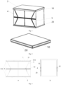
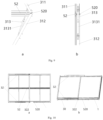
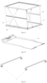
Fig. 1 is a schematic diagram of a structure of a vehicle-mounted hardtop tent in an unfolded state according to an embodiment of the present invention; -
Fig. 2 is a schematic diagram of the structure of the vehicle-mounted hardtop tent in a folded state according to an embodiment of the present invention; -
Fig. 3a is a schematic front view of a vehicle-mounted hardtop tent in an unfolded state according to an embodiment of the present invention; -
Fig. 3b is a schematic side view of the vehicle-mounted hardtop tent in the unfolded state according to an embodiment of the present invention; -
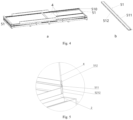
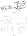
Fig. 4a is a schematic diagram of a structure of a first folding structure according to an embodiment of the present invention; -
Fig. 4b is a schematic diagram of the structure of the first folding structure according to an embodiment of the present invention; -
Fig. 5 is a schematic diagram of the structure of the first folding structure according to an embodiment of the present invention; -
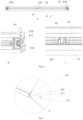
Fig. 6a is a schematic front view of a second folding structure according to an embodiment of the present invention; -
Fig. 6b is a schematic diagram of a partial enlargement of the structure ofFig. 6a according to an embodiment of the present invention; -
Fig. 6c is a schematic diagram of a partial enlargement of the structure ofFig. 6a according to an embodiment of the present invention; -
Fig. 7 is a schematic diagram of a partial enlargement of the structural ofFig. 6a according to an embodiment of the present invention; -
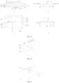
Fig. 8a is a schematic diagram of a support arm structure in an unfolded state according to an embodiment of the present invention; -
Fig. 8b is a schematic diagram of the support arm structure in a folded state according to an embodiment of the present invention; -
Fig. 9a is a schematic front view of a support arm structure in an unfolded state according to the embodiment of the present invention; -
Fig. 9b is a schematic side view of the support arm structure in a folded state according to an embodiment of the present invention; -
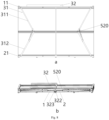
Fig. 10a is a schematic top view of an installation position of a chain according to an embodiment of the present invention; -
Fig. 10b is a schematic side view of the installation position of the chain according to an embodiment of the present invention; -
Fig. 11a is a schematic diagram of a structure of a vehicle-mounted hardtop tent in an unfolded state according to another embodiment of the present invention; -
Fig. 11b is a schematic diagram of the structure of the vehicle-mounted hardtop tent in a folded state according to another embodiment of the present invention; -
Fig. 12a is a schematic perspective view of the vehicle-mounted hardtop tent in an unfolded state according to an embodiment of the present invention; -
Fig. 12b is a schematic front view of the structure of the vehicle-mounted hardtop tent in an unfolded state according to an embodiment of the present invention; -
Fig. 12c is a schematic bottom view of the structure of the vehicle-mounted hardtop tent in an unfolded state according to an embodiment of the present invention; -
Fig. 12d is a schematic right view of the structure of the vehicle-mounted hardtop tent in an unfolded state according to an embodiment of the present invention; -
Fig. 13a is a schematic perspective view of the vehicle-mounted hardtop tent in a folded state according to an embodiment of the present invention; -
Fig. 13b is a schematic front view of the structure of the vehicle-mounted hardtop tent in a folded state according to an embodiment of the present invention; -
Fig. 13c is a schematic bottom view of the structure of the vehicle-mounted hardtop tent in a folded state according to an embodiment of the present invention; -
Fig. 13d is a schematic right view of the structure of the vehicle-mounted hardtop tent in a folded state according to an embodiment of the present invention; -
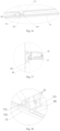
Fig. 14 is a schematic diagram of a structure of a third movable connection of a scissor-blade structure of a vehicle-mounted hardtop tent according to an embodiment of the present invention; -
Fig. 15 is a schematic diagram of a structure of a fourth movable connection of the scissor-blade structure of the vehicle-mounted hardtop tent according to an embodiment of the present invention; -
Fig. 16 is a schematic diagram of a structure of a fifth movable connection of the scissor-blade structure of the vehicle-mounted hardtop tent according to an embodiment of the present invention; -
Fig. 17 is a schematic diagram of a structure of a fixing site of the push-rod motor according to an embodiment of the present invention; -
Fig. 18 is a schematic diagram of a structure of a fifth movable connection according to an embodiment of the present invention; -
Fig. 19 is a schematic diagram of perspective view of a skeleton of a vehicle-mounted hardtop tent in an unfolded state according to an embodiment of the present invention; -
Fig. 20 is a schematic diagram of a structure of a second top frame cap of a vehicle-mounted hardtop tent according to an embodiment of the present invention; -
Fig. 21 is a schematic diagram of a structure of main body of a vehicle-mounted hardtop tent according to another embodiment of the present invention; -
Fig. 22 is a schematic diagram of a structure of a second bottom frame chassis of a vehicle-mounted hardtop tent according to an embodiment of the present invention; -
Fig. 23 is a schematic diagram of a structure of an onboard tent-fixing crossbar of a vehicle-mounted hardtop tent according to an embodiment of the present invention. -
- 1: Top frame; 10: First top frame cap
- 101: Second top frame cap; 11: Upper panel corner
- 2: Bottom frame; 20: First bottom frame chassis
- 201: Second top frame chassis; 21: Lower panel corner
- 3: Lifting mechanism; 31: Support arm structure
- 311: Upper support arm; 312: Lower support arm
- 313: Hydraulic mechanism; 3131: Hydraulic support bracket
- 32: Chain-form lifting mechanism; 322: Chain
- 323: Accommodating box
- 4: Side panel; 41: Parallel panel surface
- 5: Folding structure; 51: First folding structure
- 510: First movable connection; 511: First pivot shaft
- 512: First connecting plate; 513: Connecting socket plug
- 52: Second folding structure; 520: Second movable connection
- 521: First connecting socket; 5212: Second connecting socket
- 6: Scissor-blade structure; 61: First support arm
- 62: Second support arm; 63: Third movable connection
- 631: Perforated pin shaft; 632: Cotter pin
- 633: First shaft sleeve
- 71: Fourth movable connection; 711: First base
- 712: Second shaft sleeve; 72: Fifth movable connection
- 721: Second base; 722: Slider
- 73: Slide rail; 74: Edge plate;
- 75: Fasten bolt
- 8: Electric push-rod; 801: First fixed rod
- 81: Push-rod motor; 82: Second fixed rod
- 821: Fixing base of push-rod motor; 83: Reinforced connecting plate
- 831: Connection base; 832: Synchronous sliding rod connection
- 84: Synchronous sliding rod 85: Limit rod
- 9: Onboard tent-fixing crossbar
- In order to further elaborate on the technical means and effects of the present invention that aims to the intended objectives of the present invention, the specific implementations, structures, features and effects provided according to the present invention are described in detail below in conjunction with the drawings and the preferred embodiments.
- As shown in
Figs. 1 and 2 , an embodiment of the present invention provides a vehicle-mounted hardtop tent, which includes atop frame 1 and abottom frame 2, alifting mechanism 3, and multiple pairs offoldable side panels 4. Thetop frame 1 is located above thebottom frame 2, and is connected to tops of theside panels 4 and afolding structure 5, respectively. Thebottom frame 2 and thetop frame 1 are both plate-shaped frames. A top frame cap that matches thetop frame 1 is provided above thetop frame 1, and a bottom frame chassis that matches thebottom frame 2 is provided below thebottom frame 2. Thebottom frame 2 and thetop frame 1 each are a quadrilateral frame, and reinforcing ribs for reinforcement of thebottom frame 2 and thetop frame 1 are arranged in parallel at intervals on both thebottom frame 2 and thetop frame 1. A first bottomframe bottom chassis 20 that brackets onto thebottom frame 2 is provided at the bottom of thebottom frame 2 in a direction close to or away from thebottom frame 2, and a firsttop frame cap 10 that brackets onto thetop frame 1 is provided at the top of thetop frame 1 in a direction close to or away from thebottom frame 2. The sum of the heights of the first bottomframe bottom chassis 20 and the firsttop frame cap 10 is not less than the sum of the heights after folding of the multiple pairs offoldable side panels 4 and afolding structure 31. Jointing at the firstbottom frame chassis 20 with edges of cap walls of the firsttop frame cap 10 can be matched and connected to each other. As shown inFigs. 9a and 9b , as an optional implementation, the top frame cap together with the bottom frame bottom chassis cover thetop frame 1 andbottom frame 2 after folding. The top frame cap may also be a secondtop frame cap 101, and the bottom frame bottom chassis may also be a second bottomframe bottom chassis 201. As shown inFigs. 20 and22 , an upper panel surface of the secondtop frame cap 101 may further be designed as an inclined form, which is configured to meet practical needs, including guiding external rainwater flow downstream, reducing driving resistance, and enhancing external aesthetics. The secondbottom frame chassis 201 may be designed as a downward concave form, which will not be described any further here. - As shown in
Figs. 3a, 3b ,4a, 4b, and 5 , in an embodiment of the present invention, thefolding structure 5 includesfirst folding structures 51, which are arranged at firstmovable connections 510 between theside panels 4 and thetop frame 1 as well as between the side panels and thebottom frame 2. Each of thefirst folding structures 51 includes afirst pivot shaft 511 and a first connectingplate 512. Thefirst pivot shaft 511 is inserted with both ends into small holes arranged on inner walls of thetop frame 1, and is connected movably to two oppositely arranged ends of an lateral edge of thetop frame 1. One side of the first connectingplate 512 is fixedly connected to an edge of aside panel 4, and the other side of the first connectingplate 512 is fixedly connected to a lateral side of thefirst pivot shaft 511. Thebottom frame 2 is provided with a second connectingsocket 5212 in a fixed manner, and afirst pivot shaft 511 is arranged inside a groove of the second connectingsocket 5212, and can rotate up to 90° within the groove. When theside panel 4 is in an unfolded state, theside panel 4 rotates downward around thefirst pivot shaft 511 to a vertical position, and a free end of theside panel 4 is in contact with and fixed to a top side of thebottom frame 2. The fixing mechanism may be implemented through an interference fit clamping or the use of a fastener to ensure stable connection. When theside panel 4 is in a folded and closed state, theside panel 4 rotates upward around thefirst pivot shaft 511 toward the interior of the vehicle-mounted hardtop tent until theside panel 4 contacts and adheres to a lower panel surface of the top frame 1 (seeFig. 5 ). - As shown in
Figs. 4a and 4b , as an alternative embodiment, a firstmovable connection 510 may be provided on thebottom frame 2. When aside panel 4 is in an unfolded and open state, theside panel 4 rotates upward around afirst pivot shaft 511 to the vertical position, and a free end of theside panel 4 is in contact with and fixed to a bottom side of thetop frame 1. When theside panel 4 is in the folded and closed state, theside panel 4 rotates downward around thefirst pivot shaft 511 toward the interior of the vehicle-mounted hardtop tent until theside panel 4 contacts and adheres to a top surface of thebottom frame 2. - As shown in
Figs. 3a, 3b ,4a, 4b ,6a, 6b, 6c, and 7 , in an embodiment of the present invention, thefolding structure 5 further comprisessecond folding structures 52. Each of thesecond folding structures 52 comprises a first connectingsocket 521 and twofirst folding structures 51. Twofirst pivot shafts 511 are respectively connected to two ends at one lateral side of the first connectingsocket 521, and ends of the first connectingplates 512 away from thefirst pivot shafts 511 are each fixedly connected toside panels 4, and other ends of theside panels 4 are respectively connected to thetop frame 1 and thebottom frame 2. The first connectingsocket 521 is further provided with connecting socket plugs 513 at both ends. The socket plugs 513 are sealed at both ends of the first connectingsocket 521. When theside panels 4 are in an unfolded state, the firstmovable connections 510 of thetop frame 1 and thebottom frame 2 move away from each other in a direction toward or away from thebottom frame 2, allowing thefirst folding structures 51 to rotate around the first connectingsocket 521 until that theside panels 4 are unfolded to the vertical position and thefirst folding structures 51 are in the same plane with the connecting socket 521 (seeFig. 3a ). When theside panels 4 are in a folded and closed state, the firstmovable connections 510 of thetop frame 1 and thebottom frame 2 approaches each other in the direction toward or away from thebottom frame 2, allowing thefirst folding structures 51 to rotate around the first connectingsocket 521 until that theside panels 4 are folded and closed to a horizontal position and theside panels 4 above and below the twosecond folding structures 52 are parallel to each other (seeFigs. 6a, 6b, and 6c ). - As shown in
Figs. 1, 2, 3a, 3b ,4a, and 4b , in an embodiment of the present invention, theside panels 4 are arranged in pairs and symmetrically positioned between thetop frame 1 and thebottom frame 2, and are movably connected to edgeplates 74 provided at edges of thetop frame 1 and thebottom frame 2, respectively. When thetop frame 1 and thebottom frame 2 move toward each other, theside panels 4 can be folded to form parallel panel surfaces 41 which are parallel to and in contact with thetop frame 1 and thebottom frame 2, respectively. When thetop frame 1 and thebottom frame 2 move away from each other, theside panels 4 unfold to an unfolded state between thetop frame 1 and thebottom frame 2. - As shown in
Figs. 8a and 8b , in an embodiment of the present invention, thelifting mechanism 3 may include a plurality ofsupport arm structures 31. Each of thesupport arm structures 31 includes anupper support arm 311 and alower support arm 312. One end of theupper support arm 311 is connected to the lower panel surface of thetop frame 1 in a movable manner, the other end thereof is connected to one end of thelower support arm 312, and the other end of thelower support arm 312 is connected to the upper panel surface of thebottom frame 2 in a movable manner. Theupper support arm 311 and thelower support arm 312 partially form a secondmovable connection 520. Theupper support arm 311 and thelower support arm 312 can be folded up and down to coincide together via the secondmovable connection 520. Each of thesupport arm structures 31 is arranged outside an edge of theside panel 4, with a coincidence surface thereof parallel to a lateral surface of the side panel, and is configured to drive thetop frame 1 to approach or move away from thebottom frame 2. - As shown in
Figs. 6a and 6b , in an embodiment of the present invention, thelifting mechanism 3 comprises two sets ofsupport arm structures 31. A panel corner formed by thetop frame 1 is called anupper panel corner 11, and a panel corner formed by thebottom frame 2 is called alower panel corner 21. Theupper support arm 311 is connected to an edge of theupper panel corner 11 of thetop frame 1, and thelower support arm 312 is connected to an edge of thelower panel corner 21 of thebottom frame 2. Twosupport arm structures 31 form as one set, and the secondmovable connections 520 of each set ofsupport arm structures 31 are arranged oppositely and located between thetop frame 1 and thebottom frame 2. The two sets ofsupport arm structures 31 are symmetrically arranged. - As shown in
Figs. 9a and 9b , in an embodiment of the present invention, thesupport arm structure 31 may further include ahydraulic mechanism 313. Thehydraulic mechanism 313 is arranged on arm surfaces of theupper support arm 311 and thelower support arm 312 of eachsupport arm structure 31, which face each other, with one end thereof being fixedly connected to thelower support arm 312 and the other end thereof being fixedly connected to theupper support arm 311. Thehydraulic mechanism 313 is ahydraulic support bracket 3131. When the vehicle-mounted hardtop tent is unfolded, thehydraulic support bracket 3131 assists thesupport arm structure 31 by exerting force to theupper support arm 311 and thelower support arm 312 by means of its internal hydraulic assistance, so that thetop frame 1 moves away from thebottom frame 2 into an unfolded state. Thehydraulic support bracket 3131 is arranged inside an accommodating space between theupper support arm 311 and the lower support arm 312 (seeFigs. 8a and 8b ). - As shown in
Figs. 8a and 8b , in an embodiment of the present invention, thelifting mechanism 3 further comprises two chain-form lifting mechanisms 32, which are symmetrically arranged on thetop frame 1 or thebottom frame 2. Each of the chain-form lifting mechanisms 32 includes a driving motor (not shown in the figure), achain 322, and anaccommodating box 323. Theaccommodating box 323 is arranged on thetop frame 1, and the driving motor is placed inside theaccommodating box 323. One end of thechain 322 is connected to an output shaft of the driving motor, and the other end thereof is fixedly connected to thebottom frame 2. To unfold the vehicle-mounted hard tent, the drive motor is actuated, and it rotates to wind thechain 322 around the output shaft, so that thetop frame 1 fixed to the other end of the chain is driven by the chain to move away from thebottom frame 2. Upon moving to a farthest position, the drive motor stops running. To fold and close the vehicle-mounted hardtop tent, the drive motor is actuated and rotates in an opposite direction to wind thechain 322 around the output shaft in reverse, so that thetop frame 1 fixed to the other end of the chain is driven by the chain to move toward thebottom frame 2. Once it reaches the nearest position, the drive motor stops. - As shown in
Figs. 10a, 10b ,11a, and 11b , in an embodiment of the present invention, thechain 322 is located between the two secondmovable connections 520, and is arranged along the direction of thetop frame 1 approaching or moving away from thebottom frame 2. Thelifting mechanism 3 is located outside theside panels 4 and connected to the edges of thetop frame 1 and thebottom frame 2, respectively, and is configured to drive thetop frame 1 to move toward or away from thebottom frame 2. The top and bottom of thelifting mechanism 3 are respectively equipped with a secondtop frame cap 101 and a second bottomframe bottom chassis 201. The secondtop frame cap 101 and the second bottomframe bottom chassis 201 are connected to thetop frame 1 and thebottom frame 2, respectively, and are configured to seal and protect thelifting mechanism 3. - As shown in
Figs. 11a, 11b, 12a, 12b, 12c, 12d ,13a, 13b, 13c, and 13d , in an embodiment of the present invention, thelifting mechanism 3 comprises a plurality of X-shaped scissor-like structures 6 arranged between thetop frame 1 and thebottom frame 2. Thefirst support arm 61 and thesecond support arm 62 are flexibly connected at a thirdmovable connection 63 on theedge plates 74 arranged at the edges of thetop frame 1 and thebottom frame 2. Thefirst support arm 61 and thesecond support arm 62 are configured to drive or support thetop frame 1 to move toward or away from thebottom frame 2. As shown inFig. 14 , the thirdmovable connection 63 is provided with afirst shaft sleeve 633, at which thefirst support arm 61 and thesecond support arm 62 are connected to each other by means of aperforated pin shaft 631 and ancotter pin 632. Thecotter pin 632 is configured to fix theperforated pin shaft 631 to prevent it from falling off. Theperforated pin 631 is configured to connect thefirst support arm 61 and thesecond support arm 62, and enable rotation of thefirst support arm 61 and thesecond support arm 62 around theperforated pin 631. - In an embodiment of the present invention, multiple or a plurality of scissor-
like structures 6 between thetop frame 1 and thebottom frame 2 are arranged in a symmetrical or neighboring manner according to an orientation and position of theside panels 4. For example, one of the scissor-like structures 6 may be positioned at the location of theside panel 4 where thesecond folding structure 52 is located, and another is positioned adjacent to said location (as shown inFigs. 12a and13a ). Alternatively, the scissor-like structures 6 may be symmetrically arranged in pairs on an outer side between thetop frame 1 and thebottom frame 2. - In an embodiment of the present invention, the scissor-
like structure 6 comprises afirst support arm 61 and asecond support arm 62 that are connected in a cross and movable manner. Both ends of both thefirst support arm 61 and thesecond support arm 62 are movably connected to the lower panel surface of thetop frame 1 and the upper panel surface of thebottom frame 2, respectively. Thefirst support arm 61 and thesecond support arm 62 at the same side are in movable connection with the lower panel surface of the top frame and the upper panel surface of the bottom frame, respectively, via a connecting piece. The movable connection includes rotational connection and sliding connection. As shown inFigs. 15 and16 , a lower end of thefirst support arm 61 is rotatably connected to the upper panel surface of thebottom frame 2 at a fourthmovable connection 71, and a top of thesecond support arm 61 is rotatably connected to the lower panel surface of thetop frame 1 at another fourthmovable connection 71. The other ends of thefirst support arm 61 and thesecond support arm 62 are connected to slidingrails 73 arranged on theedge plates 74 on the lower panel surface of thetop frame 1 and the upper panel surface of thebottom frame 2, respectively. As shown inFigs. 15 and16 , the top of thefirst support arm 61 is slidably connected to the lower panel surface of thetop frame 1 at a fifthmovable connection 72, and the lower end of thesecond support arm 62 is slidably connected to the upper panel surface of thebottom frame 2 at another fifthmovable connection 72. - In an embodiment of the present invention, the rotational connection at the fourth
movable connection 71 is shown inFig. 15 . Asecond shaft sleeve 712 is provided on thefirst support arm 61, and afirst base 711 is provided on the upper panel surface of thebottom frame 2. Thefirst base 711 and thesecond shaft sleeve 712 are movably connected by means of aperforated pin shaft 631 and acotter pin 632. Thefirst base 711 is configured to constrain movement but enable rotation of thefirst support arm 61 and thesecond support arm 62. Theperforated pin shaft 631 is configured to movably connect thefirst base 711 with thesecond shaft sleeve 712. - In an embodiment of the present invention, the rotational connection at the fifth
movable connection 72 is shown inFig. 16 .Second shaft sleeves 712 are provided on thesecond support arms 62, and slidingrails 73 are provided symmetrically on both sides of the upper panel surface of thebottom frame 2. The sliding rails 73 are arranged along the edges of the lower panel surface of the top frame as well as the upper panel surface of the bottom frame. Aslider 722 is provided on a rail of the slidingrail 73, and a top surface of theslider 722 is connected to a movable connector. Theslider 722 is configured to fit to the rail and link the movable connector to slide along the rail of theslide rail 73. The movable connector includes thesecond shaft sleeve 712 and asecond base 721. Thesecond base 721 is configured to movably connect thesecond shaft sleeve 712 and drive thefirst support arm 61 or thesecond support arm 62 to slide along the rail of the slidingrail 73. Theslide rail 73 is configured to constrain movement of theslider 722 and guide the slider to move in a straight line along theslide rail 73. Aperforated pin shaft 631 passes through small apertures arranged on thesecond shaft sleeve 712 and thesecond base 721, and acotter pin 632 is provided to constrain movement of the loosen perforatedpin shaft 631. Tops of thefirst support arm 61 and thesecond support arm 62 support thetop frame 1 to move toward or away from thebottom frame 2 over thebottom frame 2 when the other ends of thefirst support arm 61 and thesecond support arm 62 are sliding on the slide rails 73 along with thesliders 722, and at the same time thefirst folding structure 51 and thesecond folding structure 52 are driven to rotate, so that the tent runs in a unfolded or folded state. - In an embodiment of the present invention, as an optional implementation, an electric push-
rod 8 is provided on a portion of thetop frame 1 or thebottom frame 2 that is between thefirst support arm 61 and thesecond support arm 62. One end of the electric push-rod 8 is fixedly connected to a bottom of the first support arm, and the other end thereof is fixedly connected to a bottom of the second support arm. One end of the electric push-rod 8 is equipped with a push-rod motor 81, which is fixed to thetop frame 1 or thebottom frame 2. - As shown in
Fig. 19 , as an optional implementation, a movablesynchronous sliding rod 84, a first fixedrod 801, a second fixedrod 82, and alimit rod 85 are provided on thebottom frame 2 and between thefirst support arms 61 or thesecond support arms 62 of the scissor-like structures 6. The push-rod motor 81 is fixedly connected to the second fixedrod 82, and an outer wall of telescopic structure of the electric push-rod 8 is fixedly connected to the first fixedrod 801, so that a direction of telescopic movement of the electric push-rod 8 can be bounded. A tip extending from the telescopic structure of the electric push-rod 8 is fixedly connected to the synchronous slidingrod 84 by means of a reinforced connectingplate 83. The reinforced connectingplate 83 is nearly parallel to the synchronous slidingrod 84, and the two are connected each other via a connectingbase 831. The reinforced connectingplate 83 is used for synchronous sliding of thesecond support arms 62 or the symmetrically arrangedsecond support arms 62, so that thetop frame 1 is driven smoothly to move away from and approach thebottom frame 2. As shown inFig. 17 , thesecond fixing rod 82 is fixedly connected to the push-rod motor 81 via a push-rodmotor fixing base 821, bolts and nuts. The push-rod motor 81 is configured to provide power for extension and retraction of the electric push-rod 8. As shown inFigs. 12c ,13c ,18 , and19 , both ends of the synchronous slidingrod 84 are provided with synchronous slidingrod connections 832. The synchronous slidingrod 84 is fixedly connected, at the synchronous slidingrod connections 832, to thesliders 722 at both ends by thesecond bases 721 usingfastening bolts 75, and each of thesecond bases 721 is connected to asecond shaft sleeve 712 via a perforated pin shaft and an cotter pin (seeFig. 18 ). The range of extension and retraction of the telescopic structure of the electric push-rod 8 is collectively defined by the following three factors: thelimit rod 85 located at the front end of the outer wall of the telescopic structure of the electric push-rod 8, a frame bar of thebottom frame 2 located at the front end of the telescopic structure of the electric push-rod 8, and the extendable and retractable stroke length of the telescopic rod in the telescopic structure. The scissor-like structure 6 can also be provided on the outer side of the laterally positioned side panels 4 (seeFigs. 12a, 12d ,13a, 13d , and19 ). - In an embodiment of the present invention, a telescopic end of the electric push-
rod 8 is fixedly connected to the movablesynchronous sliding rod 84, and movable synchronous slidingrod 84 is fixedly connected to thefirst support arm 61 or thesecond support arm 62 on aslide rail 73, so that the synchronous slidingrod 84 drives thefirst support arm 61 or thesecond support arm 62 to slide along theslide rail 73. When the push-rod motor 81 runs to drive the electric push-rod 8 to retract, one of thefirst support arm 61 and thesecond support arm 62 slides on the slidingrail 73 in a direction toward the other, so that the tops of thefirst support arm 61 and thesecond support arm 62 approach each other, or the bottoms of thefirst support arm 61 and thesecond support arm 62 approach each other. At the same time, the scissor-like structure 6 unfolds from thebottom frame 2, allowing thetop frame 1 to move away from thebottom frame 2. When the electric push-rod 8 retracts to drive the synchronous slidingrod 84 to press against thelimit rod 85, the bottoms or tops of thefirst support arm 61 and thesecond support arm 62 approach to the nearest position, at which time thetop frame 1 moves away from thebottom frame 2 to the farthest position (as shown inFigs. 11b, 12a, 12b, 12c, and 12d ). When the push-rod motor 81 runs to drive the electric push-rod 8 to extend, one of thefirst support arm 61 and thesecond support arm 62 slides on the slidingrail 73 in a direction away from the other, so that the tops of thefirst support arm 61 and thesecond support arm 62 move away from each other, or the bottoms of thefirst support arm 61 and thesecond support arm 62 move away from each other. At the same time, the scissor-like structure 6 folds and closes onto thebottom frame 2, allowing thetop frame 1 to move toward thebottom frame 2. When the electric push-rod 8 extends to drive the synchronous slidingrod 84 to press against an inner frame bar of the bottom frame 2 (or when the electric push-rod 8 extends to its maximum length), the bottom or tops of thefirst support arm 61 and thesecond support arm 62 move away from each other to the farthest distance, at which time thetop frame 1 approaches thebottom frame 2 to the nearest position (as shown in the folded state inFigs. 11a ,13a, 13b, 13c, and 13d ). - In an embodiment of the present invention, through retraction and extension, the above electric push-
rod 8 enables thetop frame 1 to move away from or approach thebottom frame 2, thereby driving thetop frame 1 over thebottom frame 2 to move away from and approach thebottom frame 2. - As shown in
Figs. 20 to 23 , the vehicle-mounted hardtop tent is made up of the various structures in the above figures sequentially corrected from top to bottom. Specifically, the secondtop frame cap 101 is fixedly connected to thetop frame 1 via bolts and nuts; the second bottomframe bottom chassis 201 is fixedly connected to thebottom frame 2 via bolts and nuts. At the same time, the second bottomframe bottom chassis 201 is fixedly connected to the body of a vehicle by means of an onboard tent-fixing crossbar 9 via bolts and nuts (as shown inFigs. 23 and11b ). - In an embodiment of the present invention, an automobile is provided and comprises: a vehicle main body and a vehicle-mounted hardtop tent as described above, wherein the vehicle-mounted hardtop tent is installed on a compartment at the top or rear of the body, covers the compartment at the top or rear of the body, and can be folded or unfolded on the compartment at the top or rear of the body.
- These above are only preferred embodiments of the preferred implementations of the present invention, rather than limitation to the preferred implementations of the present invention in any form. While the preferred implementations of the present invention have been disclosed as above by those preferred embodiments, it is not intended to limit the preferred embodiments of the present invention. Any technical personnel familiar with the field can obtain equivalent implementations by performing equivalent changes like some modifications or decorations on the basis of the above disclosed technical contents without departing from the scope of the technical solutions of the preferred implementations of the present invention. Any simple modifications, equivalent changes and decorations made to the above embodiments according to the technical essence of the preferred implementations of the present invention, which are not separated from the technical solutions of the preferred implementations of the present invention, should be still included within the scope of the technical solutions of the preferred embodiments of the present invention.
Claims (15)
- A vehicle-mounted hardtop tent, comprising: a top frame and a bottom frame, a lifting mechanism, and multiple pairs of foldable side panels, wherein:the top frame is located above the bottom frame;the side panels are arranged in pairs and symmetrically between the top frame and the bottom frame, and are respectively connected to an edge of one of the top frame and the bottom frame;when the top frame and the bottom frame approach each other, the side panels are configured to fold into a panel surface, which is substantially parallel to the top frame and the bottom frame;when the top frame and the bottom frame move away from each other, the side panels are configured to unfold between the top frame and the bottom frame; andthe lifting mechanism is arranged adjacent to the side panels and connected to edges of the top frame and the bottom frame, and is configured to drive the top frame to move toward or away from the bottom frame.
- The vehicle-mounted hardtop tent according to claim 1, wherein:the vehicle-mounted hardtop tent further comprises folding structures that connect the side panels to the edges of the top frame and the bottom frame in a movable manner;the folding structures comprise first folding structures arranged at first movable connections between the side panels, the top frame, and the bottom frame;each of the first folding structures comprises a first pivot shaft and a first connecting plate; andthe first pivot shaft is movably connected to both lateral sides of the top frame, one end of the first connecting plate is fixedly connected to a side panel, and the other end of the first connecting plate is fixedly connected to the first pivot shaft.
- The vehicle-mounted hardtop tent according to claim 2, wherein:the folding structures further comprise second folding structures;each of the second folding structures comprises a connecting socket and a first folding structure; andtwo first pivot shafts are respectively connected to both ends of the connecting socket in a movable manner, one end of the first connecting plate that is away from the first pivot shaft is connected to a side panel, and other ends are respectively connected to the top frame and the bottom frame in a movable manner.
- The vehicle-mounted hardtop tent according to claim 1, wherein:the lifting mechanism comprises a plurality of support arm structures;each of the support arm structures comprises an upper support arm and a lower support arm;one end of the upper support arm is connected to a lower panel surface of the top frame, the other end of the upper support arm is connected to one end of the lower support arm, and the other end of the lower support arm is connected to an upper panel surface of the bottom frame; andthe upper support arm and the lower support arm form a second movable connection, and the upper support arm and the lower support arm are folded up and down through the second movable connection, each support arm structure is arranged outside an edge of a side panel, and is configured to drive the top frame to move toward or away from the bottom frame.
- The vehicle-mounted hardtop tent according to claim 4, wherein:the support arm structures are arranged in two symmetrically positioned sets;each of upper support arms is connected to an edge of a panel corner of the top frame, and each of lower support arms is connected to an edge of a panel corner of the bottom frame; andtwo support arm structures form one set, and second movable connections of each set of the support arm structures are opposite to each other.
- The vehicle mounted hardtop tent according to claim 5, wherein:the support arm structure further comprises a hydraulic mechanism; andthe hydraulic mechanism is arranged on arm surfaces of the upper support arm and the lower support arm which face each other, with one end of the hydraulic mechanism fixedly connected to the lower support arm and the other end fixedly connected to the upper support arm.
- The vehicle-mounted hardtop tent according to claim 5, wherein:the lifting mechanism further comprises a plurality of chain-form lifting mechanisms;the plurality of chain-form lifting mechanisms are symmetrically arranged on the top frame or the bottom frame;each of the chain-form lifting mechanisms comprises a driving motor, a chain, and an accommodating box; andthe accommodating box is arranged on the top frame, the driving motor is arranged inside the accommodating box, one end of the chain is connected to an output shaft of the driving motor, and the other end of the chain is fixedly connected to the bottom frame.
- The vehicle-mounted hardtop tent according to claim 7, wherein the chain is located in a middle of the two second movable connections, and is arranged in a direction that the top frame approaches or moves away from the bottom frame.
- The vehicle-mounted hardtop tent according to claim 3, wherein:the lifting mechanism comprises a plurality of X-shaped scissor-like structures arranged between the top frame and the bottom frame;each of the scissor-like structures comprises a first support arm and a second support arm that are connected in a cross and movable manner; andboth ends of each of the first support arm and the second support arm are connected to a lower panel surface of the top frame and an upper panel surface of the bottom frame, respectively, allowing lifting and lowering of the top frame above the bottom frame
- The vehicle-mounted hardtop tent according to claim 9, wherein:one end of the first support arm and one end of the second support arm are connected to one of the lower panel surface of the top frame and the upper panel surface of the bottom frame, respectively; andthe other end of the first support arm and the other end of the second support arm are connected to the other one of the lower panel surface of the top frame and the upper panel surface of the bottom frame, respectively.
- The vehicle-mounted hardtop tent according to claim 10, wherein:an electric push-rod is provided on a portion of the top frame or the bottom frame that is between the first support arm and the second support arm, with one end of the electric push-rod fixedly connected to the first support arm and the other end fixedly connected to the second support arm;when the electric push-rod retracts, one of the first support arm and the second support arm slides along a sliding rail towards the other, allowing tops of the first support arm and the second support arm to approach each other, or allowing bottoms of the first support arm and the second support arm to approach each other; andwhen the electric push-rod extends out, one of the first support arm and the second support arm slides along the sliding rail away from the other, allowing the tops of the first support arm and the second support arm to move away from each other, or allowing the bottoms of the first support arm and the second support arm to move away from each other.
- The vehicle-mounted hardtop tent according to claim 11, wherein:the electric push-rod is fixedly connected to a synchronous sliding rod;the synchronous sliding rod is fixedly connected to a corresponding first or second support arm on the slide rail; andthe synchronous sliding rod is configured to drive the first or second support arm to slide along the slide rail.
- The vehicle-mounted hardtop tent according to claim 9, wherein the scissor-like structures between the top frame and the bottom frame are arranged in a symmetrical or neighboring manner according to an orientation and position of the side panels.
- The vehicle-mounted hardtop tent according to claim 1, wherein the bottom frame and the top frame are plate-like frames, a top frame cap is provided onto the top frame, and a bottom frame chassis is provided beneath the bottom frame.
- An automobile, comprising:a main body; andthe vehicle-mounted hardtop tent according to any one of claims 1 to 14, wherein the vehicle-mounted hardtop tent is installed on a compartment at a top or rear of the main body, covers the compartment at the top or rear of the main body, and is configured to be folded or unfolded on the compartment at the top or rear of the main body.
Applications Claiming Priority (2)
| Application Number | Priority Date | Filing Date | Title |
|---|---|---|---|
| CN202211035763.0A CN117803240A (en) | 2022-08-26 | 2022-08-26 | A vehicle-mounted hard-top tent and its vehicle |
| PCT/CN2022/120339 WO2024040664A1 (en) | 2022-08-26 | 2022-09-21 | Vehicle-mounted hardtop tent, and automobile thereof |
Publications (2)
| Publication Number | Publication Date |
|---|---|
| EP4579052A1 true EP4579052A1 (en) | 2025-07-02 |
| EP4579052A4 EP4579052A4 (en) | 2025-12-03 |
Family
ID=90012212
Family Applications (1)
| Application Number | Title | Priority Date | Filing Date |
|---|---|---|---|
| EP22956208.7A Pending EP4579052A4 (en) | 2022-08-26 | 2022-09-21 | VEHICLE-MOUNTED HARDTOP TENT AND MOTORHOME FOR IT |
Country Status (5)
| Country | Link |
|---|---|
| US (1) | US20260062946A1 (en) |
| EP (1) | EP4579052A4 (en) |
| CN (1) | CN117803240A (en) |
| AU (1) | AU2022475520A1 (en) |
| WO (1) | WO2024040664A1 (en) |
Families Citing this family (1)
| Publication number | Priority date | Publication date | Assignee | Title |
|---|---|---|---|---|
| AU2025200559B1 (en) * | 2025-01-28 | 2025-12-18 | Bushwakka Pty Ltd | Rooftop tent |
Family Cites Families (11)
| Publication number | Priority date | Publication date | Assignee | Title |
|---|---|---|---|---|
| KR100406550B1 (en) * | 2003-07-09 | 2003-11-21 | Sung Jin Gang | Car tent |
| CN104632866B (en) * | 2014-12-05 | 2017-07-14 | 佛山市南海五湖志威五金塑料电器厂 | Hinge and apply its music score panel |
| KR101745250B1 (en) * | 2016-03-08 | 2017-06-09 | 김영원 | Tent Mounted on a Roof of Vehicle |
| CN110700637A (en) * | 2019-10-17 | 2020-01-17 | 乐歌人体工学科技股份有限公司 | Folding private warehouse |
| CN213442037U (en) * | 2020-08-27 | 2021-06-15 | 厦门市丰青装饰设计有限公司 | Hard car roof tent capable of being opened and recovered quickly |
| CN213449752U (en) * | 2020-09-03 | 2021-06-15 | 陈兵 | Novel automatic folding roof tent |
| KR102290071B1 (en) * | 2021-02-09 | 2021-08-13 | 이유경 | Hard rooftop tent |
| US11680421B2 (en) * | 2021-02-09 | 2023-06-20 | Ikamper Co., Ltd. | Vehicular rooftop tent |
| CN114251013A (en) * | 2022-02-17 | 2022-03-29 | 白如祥 | A fully automatic vertical lift roof tent |
| CN114407761B (en) * | 2022-03-02 | 2025-07-04 | 湖北旅居家专用汽车有限公司 | Automatic lifting folding box |
| CN114734905A (en) * | 2022-03-30 | 2022-07-12 | 无锡升合汽车科技有限公司 | Folding compartment and folding car as a house thereof |
-
2022
- 2022-08-26 CN CN202211035763.0A patent/CN117803240A/en active Pending
- 2022-09-21 US US19/106,903 patent/US20260062946A1/en active Pending
- 2022-09-21 EP EP22956208.7A patent/EP4579052A4/en active Pending
- 2022-09-21 AU AU2022475520A patent/AU2022475520A1/en active Pending
- 2022-09-21 WO PCT/CN2022/120339 patent/WO2024040664A1/en not_active Ceased
Also Published As
| Publication number | Publication date |
|---|---|
| WO2024040664A1 (en) | 2024-02-29 |
| US20260062946A1 (en) | 2026-03-05 |
| AU2022475520A1 (en) | 2025-04-10 |
| CN117803240A (en) | 2024-04-02 |
| EP4579052A4 (en) | 2025-12-03 |
Similar Documents
| Publication | Publication Date | Title |
|---|---|---|
| CN211969275U (en) | Car as a house of roof liftable formula | |
| CN101754878A (en) | Multifunctional vehicle awning frame | |
| AU2024204147B2 (en) | Multifunctional double-layer lift-type vehicle-mounted tent | |
| US20260062946A1 (en) | Vehicle-mounted hardtop tent, and automobile thereof | |
| CN218623632U (en) | Folding tent frame with bed board | |
| CN206468097U (en) | A kind of rooftop tent | |
| CN105150912A (en) | Double-layer full-automatic recreational vehicle | |
| CN216714039U (en) | Automatic vertical lifting connecting rod folding roof tent | |
| CN112062011A (en) | Cantilever crane system and have bow member car of this cantilever crane system | |
| CN213297388U (en) | Roof tent for simply collecting and unfolding outdoor tourism | |
| CN215883453U (en) | Multifunctional expansion recreational vehicle | |
| CN215331854U (en) | Waterproof car roof tent support structure | |
| CN105172661A (en) | Double-deck full-automatic villa recreational vehicle | |
| CN111197421B (en) | A hydraulic telescopic maintenance tent | |
| AU2019100764A4 (en) | Roof tent and bedding for same | |
| CN221030913U (en) | Shutter stacking type retracting mechanism for outdoor shutter awning | |
| CN218912390U (en) | Multifunctional command shelter | |
| CN113585835B (en) | Intelligent telescopic hood | |
| CN204956251U (en) | Double -deck full -automatic villa car as a house | |
| CN212507951U (en) | Internal inverted translation window structure | |
| CN220014629U (en) | Functional frame for stage shelter | |
| CN204956250U (en) | Double -deck full -automatic sightseeing car as a house | |
| CN220849053U (en) | Vehicle-mounted tent with automatic supporting mechanism | |
| CN212685397U (en) | Flat-pushing type canopy system | |
| CN223446747U (en) | A folding tent linkage structure and a car using the same |
Legal Events
| Date | Code | Title | Description |
|---|---|---|---|
| STAA | Information on the status of an ep patent application or granted ep patent |
Free format text: STATUS: THE INTERNATIONAL PUBLICATION HAS BEEN MADE |
|
| PUAI | Public reference made under article 153(3) epc to a published international application that has entered the european phase |
Free format text: ORIGINAL CODE: 0009012 |
|
| STAA | Information on the status of an ep patent application or granted ep patent |
Free format text: STATUS: REQUEST FOR EXAMINATION WAS MADE |
|
| 17P | Request for examination filed |
Effective date: 20250326 |
|
| AK | Designated contracting states |
Kind code of ref document: A1 Designated state(s): AL AT BE BG CH CY CZ DE DK EE ES FI FR GB GR HR HU IE IS IT LI LT LU LV MC MK MT NL NO PL PT RO RS SE SI SK SM TR |
|
| REG | Reference to a national code |
Ref country code: DE Ref legal event code: R079 Free format text: PREVIOUS MAIN CLASS: E04H0015480000 Ipc: B60P0003340000 |
|
| A4 | Supplementary search report drawn up and despatched |
Effective date: 20251030 |
|
| DAV | Request for validation of the european patent (deleted) | ||
| DAX | Request for extension of the european patent (deleted) | ||
| RIC1 | Information provided on ipc code assigned before grant |
Ipc: B60P 3/34 20060101AFI20251024BHEP Ipc: E04H 15/48 20060101ALI20251024BHEP |