EP4578813A1 - Construction planning assistance device and program - Google Patents
Construction planning assistance device and program Download PDFInfo
- Publication number
- EP4578813A1 EP4578813A1 EP23871726.8A EP23871726A EP4578813A1 EP 4578813 A1 EP4578813 A1 EP 4578813A1 EP 23871726 A EP23871726 A EP 23871726A EP 4578813 A1 EP4578813 A1 EP 4578813A1
- Authority
- EP
- European Patent Office
- Prior art keywords
- crane
- ground contact
- attaching
- contact pressure
- component
- Prior art date
- Legal status (The legal status is an assumption and is not a legal conclusion. Google has not performed a legal analysis and makes no representation as to the accuracy of the status listed.)
- Pending
Links
Images






Classifications
-
- B—PERFORMING OPERATIONS; TRANSPORTING
- B66—HOISTING; LIFTING; HAULING
- B66C—CRANES; LOAD-ENGAGING ELEMENTS OR DEVICES FOR CRANES, CAPSTANS, WINCHES, OR TACKLES
- B66C23/00—Cranes comprising essentially a beam, boom, or triangular structure acting as a cantilever and mounted for translatory of swinging movements in vertical or horizontal planes or a combination of such movements, e.g. jib-cranes, derricks, tower cranes
- B66C23/88—Safety gear
- B66C23/90—Devices for indicating or limiting lifting moment
-
- B—PERFORMING OPERATIONS; TRANSPORTING
- B66—HOISTING; LIFTING; HAULING
- B66C—CRANES; LOAD-ENGAGING ELEMENTS OR DEVICES FOR CRANES, CAPSTANS, WINCHES, OR TACKLES
- B66C13/00—Other constructional features or details
- B66C13/16—Applications of indicating, registering, or weighing devices
-
- G—PHYSICS
- G06—COMPUTING OR CALCULATING; COUNTING
- G06F—ELECTRIC DIGITAL DATA PROCESSING
- G06F3/00—Input arrangements for transferring data to be processed into a form capable of being handled by the computer; Output arrangements for transferring data from processing unit to output unit, e.g. interface arrangements
- G06F3/01—Input arrangements or combined input and output arrangements for interaction between user and computer
- G06F3/048—Interaction techniques based on graphical user interfaces [GUI]
- G06F3/0481—Interaction techniques based on graphical user interfaces [GUI] based on specific properties of the displayed interaction object or a metaphor-based environment, e.g. interaction with desktop elements like windows or icons, or assisted by a cursor's changing behaviour or appearance
- G06F3/0482—Interaction with lists of selectable items, e.g. menus
-
- G—PHYSICS
- G06—COMPUTING OR CALCULATING; COUNTING
- G06F—ELECTRIC DIGITAL DATA PROCESSING
- G06F3/00—Input arrangements for transferring data to be processed into a form capable of being handled by the computer; Output arrangements for transferring data from processing unit to output unit, e.g. interface arrangements
- G06F3/01—Input arrangements or combined input and output arrangements for interaction between user and computer
- G06F3/048—Interaction techniques based on graphical user interfaces [GUI]
- G06F3/0484—Interaction techniques based on graphical user interfaces [GUI] for the control of specific functions or operations, e.g. selecting or manipulating an object, an image or a displayed text element, setting a parameter value or selecting a range
- G06F3/04842—Selection of displayed objects or displayed text elements
-
- G—PHYSICS
- G06—COMPUTING OR CALCULATING; COUNTING
- G06F—ELECTRIC DIGITAL DATA PROCESSING
- G06F30/00—Computer-aided design [CAD]
- G06F30/10—Geometric CAD
- G06F30/13—Architectural design, e.g. computer-aided architectural design [CAAD] related to design of buildings, bridges, landscapes, production plants or roads
-
- G—PHYSICS
- G06—COMPUTING OR CALCULATING; COUNTING
- G06F—ELECTRIC DIGITAL DATA PROCESSING
- G06F30/00—Computer-aided design [CAD]
- G06F30/20—Design optimisation, verification or simulation
-
- G—PHYSICS
- G06—COMPUTING OR CALCULATING; COUNTING
- G06F—ELECTRIC DIGITAL DATA PROCESSING
- G06F2119/00—Details relating to the type or aim of the analysis or the optimisation
- G06F2119/14—Force analysis or force optimisation, e.g. static or dynamic forces
Definitions
- the present invention relates to a construction planning assistance system and a program.
- the construction planning assistance system 1 is connected to a building storage part 2 and a crane storage part 3 via a network 5.
- the network 5 may be any communication network for data communication between devices without particular limitation, for example, may be a local area network (LAN).
- a communication line for the data communication may be wired or wireless, or a combination of wired communication and wireless communication may be adopted.
- Examples of the wireless LAN include the Wi-Fi (registered trademark) and the Bluetooth (registered trademark).
- the building storage part 2 stores information about a building to establish the building model 30 (see Fig. 4 ).
- the information about the building include attribute information about positions, dimensions, materials, gravity center positions of components constituting an entirety of the building.
- the building model 30 is created by simulating the entirety of the building as a model on the basis of the information about the building.
- the crane storage part 3 stores information about the crane 50 to establish a crane model 40 (see Fig. 4 ).
- Examples of the information about the crane 50 include a name, a type, a working radius, and dimensions of the crane 50.
- the crane 50 includes a traveling body 60 having the crawlers 61, a slewing body 70 mounted on the traveling body 60, and a slewing device 65 that enables the slewing body 70 to slew with respect to the traveling body 60.
- the slewing body 70 has an operating compartment 71 and a counterweight 72.
- the crane 50 further includes the boom 80 mounted on the top of the slewing body 70 and a jib 90 extending outward from an upper distal end of the boom 80 in a tiltable manner.
- the boom 80 has a lower proximal end supported by the slewing body 70 in such a manner as to be tiltable about a boom foot pin 81.
- the jib 90 has a proximal end connected to the upper end of the boom 80 in such a manner as to be tiltable about a jib foot pin 91.
- the crane 50 includes a wire rope 92 extending directly downward from a distal end of the jib 90, and a hook 93 attached to a distal end of the wire rope 92.
- the controller 10 includes a display control part 11 that controls displaying on the display part 22, an information acquisition part 12 that acquires information, and a calculation part 13 that calculates a ground contact pressure and other parameter.
- Fig. 4 is an illustration of an example model display screen image 41 displayed on the display part 22 by the model display control part 111.
- the model display control part 111 causes the display part 22 to display the building model 30 corresponding to the building and having the three-dimensional shape in a three-dimensional virtual space displayed in the model display screen image 41 by using the information about the building model 30 stored in the building storage part 2.
- the model display control part 111 further causes the display part 22 to display the crane model 40 corresponding to the crane 50 in the three-dimensional virtual space displayed in the model display screen image 41 by using the information about the crane model 40 stored in the crane storage part 3.
- the building model 30 illustrated in Fig. 4 includes a component model 31 corresponding to a component constituting the building.
- the building model 30 includes a component model group 32 including a plurality of component models 31.
- the information acquisition part 12 has a component information acquisition part 121 or first acquisition part that acquires, from the building storage part 2, information about one component model 31 designated from the component model group 32 that constitutes the building model 30 displayed on the display part 22.
- Examples of the designation of the one component model 31 from the component model group 32 may include clicking the one component model 31 by a mouse serving as an example of the manipulation part 23.
- the manipulation part 23 includes a touch screen, the designation may be made by touching the one component model 31
- Fig. 5 is an illustration of an example state where the one component model 31 is designated.
- the model display control part 111 displays the designated one component model 31 in a highlighted manner.
- the designated component model 31 is filled in black.
- the information acquisition part 12 further has a crane information acquisition part 122 or second acquisition part that acquires, from the crane storage part 3, the information about the crane 50 corresponding to the crane model 40 arranged in the vicinity of the building model 30 as displayed on the display part 22.
- the crane calculation part 131 calculates, on the basis of the information about the one component model 31 acquired by the component information acquisition part 121 and the information about the crane 50 acquired by the crane information acquisition part 122, values related to the crane 50 including the posture of the crane 50 and a load factor therefor in attachment of a component (hereinafter, referred to as a "target component" as well) corresponding to the one component model 31 by the crane 50.
- a component hereinafter, referred to as a "target component" as well
- the ground contact pressure calculation part 132 has an attaching calculation part 132a that calculates an attaching-time ground contact pressure acting in attachment of the target component by hoisting and lowering the target component, and a rising calculation part 132b that calculates a rising-time ground contact pressure acting in rising of the crane.
- Each ground contact pressure is calculatable in accordance with a certain standard, such as JIS A8509, or other standard. Alternatively, another calculation way may be employed.
- the building model 30 includes a component model 31 located closer to the crane 50 and another component model 31 located away from the crane 50.
- the component models 31 are located at various heights from the ground surface.
- the attaching calculation part 132a calculates ground contact pressures respectively applied at four points of a front end A and a rear end B of a left crawler 61L (see Fig. 8 ) and a front end C and a rear end D of a right crawler 61R (see Fig. 8 ) when the crane 50 comes to the posture of hoisting the target component corresponding to the one component model 31 acquired by the component information acquisition part 121.
- the attaching calculation part 132a further calculates a length L1 (see Fig. 8 ) associated with a load resulting from pressing by the left crawler 61L and a length L2 (see Fig. 8 ) associated with a load resulting from pressing by the right crawler 61R.
- the attaching calculation part 132a calculates a maximum ground contact pressure and a slewing angle under the maximum ground contact pressure when the slewing body 70 slews at 360° in the posture or state of hoisting the target component.
- the attaching calculation part 132a calculates the ground contact pressure by a known way with at least any one of the posture of the crane 50, the length of the boom 80, the length of the jib 90, the weight of the hook 93, the weight of the counterweight 72, an angle of the boom 80, an angle of the jib 90, a working radius, a hoisted load (excluding the weight of the hook 93), the total weight of the crane 50 (excluding the hoisted load), and the slewing angle of the slewing body 70.
- the posture of the crane 50 include a luffing tower hoisting posture, a crawler crane hoisting posture, a tower crane hoisting posture.
- the rising calculation part 132b calculates a rising-time ground contact pressure acting in rising. Concerning the rising, when the slewing body 70 has a slewing angle of 0°, the boom 80 and the jib 90 maximally extend and the jib 90 is closed to be located under the boom 80. For instance, the boom 80 and the jib 90 come into this state when assembled to the slewing body 70.
- the first way is called an inward holding way of causing the boom 80 to rise while holding the jib 90 from the state where the jib 90 is located under the boom 80.
- the second way is called an extraction way of causing the jib 90 to open and extend to align with the boom 80 and causing both the boom 80 and the jib 90 to stand from a state where the boom and the jib lie along the ground.
- the crane 50 returns from a working posture to an original state preceding to rising when the boom 80 and the jib 90 are lowered. That is to say, a ground contact pressure acts to the ground in each of the rising and the lowering in the same manner.
- the ground contact pressure in one of the ways may be higher than the ground contact pressure in the other of the ways depending on a specification of a crane.
- the ground contact pressure in rising is likely to be higher than the ground contact pressure in normal working. From these perspectives, a grasp of a rising-time ground contact pressure in advance is important.
- the crane display control part 112 further displays a transition button 42a given with the words "ground contact pressure details" in the crane information screen image 42.
- the crane display control part 112 displays the transition button 42a near the value of the ground contact pressure at a lower right end in the crane information screen image 42.
- the ground contact pressure display control part 113 displays, in the ground contact pressure detail screen image 43, respective values of ground contact pressures at the four points of the front end A, the rear end B, the front end C, and the rear end D4 in a present posture, as calculated by the attaching calculation part 132a, together with the unit "t/m 2 " for each ground contact pressure.
- the ground contact pressure display control part 113 further displays, in the ground contact pressure detail screen image 43, the length L1 associated with the load resulting from pressing by the left crawler 61L and the length L2 associated with the load resulting from pressing by the right crawler 61R together with the unit "m" of each length, the lengths being calculated by the attaching calculation part 132a.
- the ground contact pressure display control part 113 displays, in the ground contact pressure detail screen image 43, a value of a rising-time ground contact pressure calculated by the rising calculation part 132b together with the unit "t/m 2 " or "t/m2".
- the ground contact pressure display control part 113 causes the display part to display, in the ground contact pressure detail screen image 43, a permissible ground contact pressure input in advance together with the unit "t/m 2 " or "t/m2". In absence of the permissible ground contact pressure, "0" is displayed as the permissible ground contact pressure.
- the ground contact pressure display control part 113 is configured to issue an alert when any of the values of the ground contact pressures at the four points of the front end A, the rear end B, the front end C, and the rear end D, the value of the maximum ground contact pressure at 360°, and the value of the rising-time ground contact pressure exceeds the permissible ground contact pressure.
- Example ways of issuing the alert include a way of expressing characters of the value of the ground contact pressure exceeding the permissible ground contact pressure in red and a way of showing a background of the characters of the value of the ground contact pressure exceeding the permissible ground contact pressure in red.
- the construction planning assistance system 1 includes the component information acquisition part 121 (serving an example of the first acquisition part) that acquires information about one component model 31 designated from the component model group 32 that constitutes the building model 30 corresponding to the building, having the three-dimensional shape, and displayed in the three-dimensional virtual space.
- the construction planning assistance system 1 further includes the crane information acquisition part 122 (serving as an example of the second acquisition part) that acquires information about the crane 50 arranged in the vicinity of the building for hoisting a component constituting the building.
- the construction planning assistance system 1 includes the attaching calculation part 132a that calculates, on the basis of the information about the one component model 31 acquired by the component information acquisition part 121 and the information about the crane 50 acquired by the crane information acquisition part 122, an attaching-time ground contact pressure being a ground contact pressure acting to the ground where the crane 50 is arranged in attachment of one component corresponding to the one component model 31 by the crane 50. Furthermore, the construction planning assistance system 1 includes the ground contact pressure display control part 113 that causes the display part 22 to display the attaching-time ground contact pressure calculated by the attaching calculation part 132a.
- the construction planning assistance system 1 having this configuration enables the user to designate one component model 31 from the component model group 32 that constitutes the building model 30 having the three-dimensional shape and then confirm, on the display part 22, a ground contact pressure in attachment of one component corresponding to the designated one component model 31.
- the configuration thus allows the user to easily grasp a ground contact pressure required for determination as to whether to protect the ground to support the crane 50 thereon. This consequently enables easy determination on the necessity or unnecessity of protection of the ground to support the crane thereon.
- a program constituting the present invention includes causing a computer to execute: first acquisition of acquiring information about one component model 31 designated from a component model group 32 that constitutes a building model 30 corresponding to a building, having a three-dimensional shape, and displayed in a three-dimensional virtual space; and second acquisition of acquiring information about a crane 50 arranged in the vicinity of the building for hoisting a component constituting the building.
- Fig. 10 is an illustration of an example component designation screen image 44 displayed on a display part 22 by the crane display control part 212.
- the crane display control part 212 may display the component designation screen image 44 illustrated in Fig. 10 by superimposing the image on a model display screen image 41 displayed by a model display control part 111.
- the component designation screen image 44 shows an acceptance button 44a given with the words "single component model designation” to accept designation of one component model 31 by a user, and an acceptance button 44b given with the words "plural component models designation” to accept designation of a plurality of component models 31 by the user.
- the crane display control part 212 may display the component designation screen image 44 and the model display screen image 41 next to each other.
- the model display control part 111 displays the designated component model 31 in a highlighted manner.
- the component information acquisition part 221 acquires information about the one component model 31 from a building storage part 2 in response to pressing of the acceptance button 44a (e.g., in response to clicking by a mouse serving as the manipulation part 23) in a state where the one component model 31 is designated.
- Fig. 11 is an illustration of an example state where a plurality of component models 31 is designated, and the acceptance button 44b is pressed.
- the model display control part 111 displays the designated component models 31 in a highlighted manner as illustrated in Fig. 11 .
- the component information acquisition part 221 acquires information about the component models 31 from the building storage part 2 in response to pressing of the acceptance button 44b in a state where the component models 31 are designated.
- a crane calculation part 131 calculates, on the basis of the information about the one component model 31 or the component models 31 acquired by the component information acquisition part 221 and the information about the crane 50 acquired by the crane information acquisition part 122, values related to the crane 50, such as the posture of the crane 50 and a load factor therefor, in attachment of a component corresponding to the one component model 31 or components corresponding to the component models 31 by the crane 50.
- Fig. 12 is a table showing an example crane information screen image 45 displayed on the display part 22 by the crane display control part 212.
- the crane display control part 212 causes the display part 22 to display a result of a calculation by the crane calculation part 131.
- the crane display control part 212 displays, in the crane information screen image 45, respective values of a length of a boom 80, a length of a jib 90, an angle of the boom 80, an angle of the jib 90, a working radius, a slewing angle of a slewing body 70, a load factor, and an attaching-time ground contact pressure per designated component model 31.
- the crane display control part 212 displays the attaching-time ground contact pressure and other information per component model 31 in a list. Specifically, the crane display control part displays identification information about the designated component models 31 in a column in a vertical direction in the crane information screen image 45 and displays results of calculations for the length of the boom 80, an attaching-time ground contact pressure, and other parameters per component model 31 in a row in a horizontal direction in the screen image.
- Fig. 13 is an illustration of an example state where one component model 31 is designated from the component models 31.
- the model display control part 111 displays the selected component model 31 in a highlighted manner (in Fig. 13 , the selected component model 31 is filled in black). For instance, this configuration allows the user to grasp a component model 31 requiring the highest attaching-time ground contact pressure among a plurality of designated component models 31.
- the ground contact pressure display control part 113 may cause the display part 22 to display a ground contact pressure detail screen image 43 about the one component model 31.
- this configuration allows the user to grasp a maximum ground contact pressure at 360° constituting detail information about a ground contact pressure for a component model 31 requiring the highest attaching-time ground contact pressure among a plurality of designated component models 31.
- a program constituting the present invention is a program that includes causing a computer to execute third acquisition of acquiring information about a plurality of component models 31 from the component model group 32.
- the attaching calculation includes calculating, on the basis of the information about the component models 31 acquired in the third acquisition and the information about the crane 50 acquired in the second acquisition, attaching-time ground contact pressures in attachment of a plurality of components respectively corresponding to the component models 31 by the crane 50.
- Display controlling includes causing the display part 22 to display the attaching-time ground contact pressures calculated in the attaching calculation.
- the present invention provides a construction planning assistance system.
- the construction planning assistance system includes: a first acquisition part that acquires information about at least one component model designated from a component model group that constitutes a building model corresponding to a building, having a three-dimensional shape, and displayed in a three-dimensional virtual space; a second acquisition part that acquires information about a crane arranged in the vicinity of the building for hoisting a component constituting the building; an attaching calculation part that calculates, on the basis of the information about the at least one component model acquired by the first acquisition part and the information about the crane acquired by the second acquisition part, an attaching-time ground contact pressure being a ground contact pressure acting to ground where the crane is arranged in attachment of at least one component corresponding to the at least component model by the crane; and a display control part that causes a display part to display the attaching-time ground contact pressure calculated by the attaching calculation part.
- the attaching calculation part may calculate a maximum ground contact pressure when the crane slews at 360° in a state of hoisting the at least one member, and the display control part may cause the display part to display the maximum ground contact pressure.
- the present invention further provides a program that includes causing a computer to execute predetermined operations.
- the predetermined operations include: first acquisition of acquiring information about at least one component model designated from a component model group that constitutes a building model corresponding to a building, having a three-dimensional shape, and displayed in a three-dimensional virtual space; second acquisition of acquiring information about a crane arranged in the vicinity of the building for hoisting a component constituting the building; attaching calculation of calculating, on the basis of the information about the at least one component model acquired in the first acquisition and the information about the crane acquired in the second acquisition, an attaching-time ground contact pressure being a ground contact pressure acting to ground where the crane is arranged in attachment of at least one component corresponding to the at least one component model by the crane; and displaying of causing a display part to display the attaching-time ground contact pressure calculated in the attaching calculation.
- the present invention provides a construction planning assistance system or other system that enables an easy grasp of a ground contact pressure required for determination as to whether to protect ground.
Landscapes
- Engineering & Computer Science (AREA)
- Physics & Mathematics (AREA)
- Theoretical Computer Science (AREA)
- Geometry (AREA)
- General Physics & Mathematics (AREA)
- General Engineering & Computer Science (AREA)
- Computer Hardware Design (AREA)
- Evolutionary Computation (AREA)
- Architecture (AREA)
- Civil Engineering (AREA)
- Structural Engineering (AREA)
- Computational Mathematics (AREA)
- Mathematical Analysis (AREA)
- Mathematical Optimization (AREA)
- Pure & Applied Mathematics (AREA)
- Human Computer Interaction (AREA)
- Mechanical Engineering (AREA)
- Management, Administration, Business Operations System, And Electronic Commerce (AREA)
- Jib Cranes (AREA)
Abstract
Description
- The present invention relates to a construction planning assistance system and a program.
- Simulation software for calculating a ground contact pressure under a static load condition for a crane in a working posture has been conventionally proposed.
- Non-patent Literature 1: Kuren Secchiatsu simyureshon [Crane Ground Pressure Simulator], Retrieved on September 13, 2022, from http://www.hsc-cranes.com/simulation/index.php/Init/index, through the Internet
- A ground contact pressure in an arrangement location for a crane needs to be calculated for determination as to whether to protect or guard ground to support the crane thereon. Unfortunately, such conventional simulation software as aforementioned demands a lot of input items, and thus is complicated. The software further requires confirmation on a plurality of matters under strict conditions for numeral values to be input, that is, requires knowledge based on experience of an expert or skilled person.
- An object of the present invention is to provide a construction planning assistance system or other system that enables an easy grasp of a ground contact pressure required for determination as to whether to protect ground.
- The present invention provides a construction planning assistance system. The construction planning assistance system includes: a first acquisition part that acquires information about at least one component model designated from a component model group that constitutes a building model corresponding to a building, having a three-dimensional shape, and displayed in a three-dimensional virtual space; a second acquisition part that acquires information about a crane arranged in the vicinity of the building for hoisting a component constituting the building; an attaching calculation part that calculates, on the basis of the information about the at least one component model acquired by the first acquisition part and the information about the crane acquired by the second acquisition part, an attaching-time ground contact pressure being a ground contact pressure acting to ground where the crane is arranged in attachment of at least one component corresponding to the at least component model by the crane; and a display control part that causes a display part to display the attaching-time ground contact pressure calculated by the attaching calculation part.
- The present invention further provides a program that includes causing a computer to execute predetermined operations. The program covers executions of the operations including: first acquisition of acquiring information about at least one component model designated from a component model group that constitutes a building model corresponding to a building, having a three-dimensional shape, and displayed in a three-dimensional virtual space; second acquisition of acquiring information about a crane arranged in the vicinity of the building for hoisting a component constituting the building; attaching calculation of calculating, on the basis of the information about the at least one component model acquired in the first acquisition and the information about the crane acquired in the second acquisition, an attaching-time ground contact pressure being a ground contact pressure acting to ground where the crane is arranged in attachment of at least one component corresponding to the at least one component model by the crane; and displaying of causing a display part to display the attaching-time ground contact pressure calculated in the attaching calculation.
-
-
Fig. 1 is a diagram showing an example schematic configuration of a construction planning assistance system according to a first embodiment. -
Fig. 2 is a block diagram showing example operational parts of the construction planning assistance system according to the first embodiment. -
Fig. 3 is a side view of an example schematic configuration of a crane. -
Fig. 4 is an illustration of an example model display screen image displayed on a display part by a model display control part. -
Fig. 5 is an illustration of an example state where one component model is designated. -
Fig. 6 is an illustration of an example crane information screen image displayed on the display part by a crane display control part. -
Fig. 7 is an illustration of an example relation between the model display screen image and the crane information screen image. -
Fig. 8 is an illustration of an example ground contact pressure detail screen image displayed on the display part by a ground contact pressure display control part. -
Fig. 9 is a block diagram showing example operational parts of a construction planning assistance system according to a second embodiment. -
Fig. 10 is an illustration of an example component designation screen image displayed on a display part by a crane display control part. -
Fig. 11 is an illustration of an example state where a plurality of component models is designated. -
Fig. 12 is a table showing an example crane information screen image displayed on the display part by the crane display control part. -
Fig. 13 is an illustration of an example state where one component model is designated from the component models. - Hereinafter, embodiments will be described with reference to the accompanying drawings.
-
Fig. 1 is a diagram showing an example schematic configuration of a constructionplanning assistance system 1 according to a first embodiment.Fig. 2 is a block diagram showing example operational parts of the constructionplanning assistance system 1 according to the first embodiment.Fig. 3 is a side view of an example schematic configuration of acrane 50. The constructionplanning assistance system 1 is effective to determine whether to protect ground to support thecrane 50 thereon after determination of a type and a specification of thecrane 50 to construct a building or structure and determination of an arrangement location for thecrane 50. Specifically, the constructionplanning assistance system 1 is configured to calculate a ground contact pressure onto the ground to support thecrane 50 thereon and to display the calculated ground contact pressure on adisplay part 22. In this respect, a user can determine the necessity or unnecessity of protection of the ground for the support in consideration of enough or not enough bearing capacity of the ground to support thecrane 50 thereon against the ground contact pressure displayed by the constructionplanning assistance system 1 and a subsidence amount of the ground falling within or being outside a permissible range. - Examples of the building here include structures fixed onto ground and having roofs and columns or walls, houses, condominiums or apartments, viaducts for highways, windmills, and other structures and buildings. A work of constructing such a building by the
crane 50 includes excavation and driving of stakes into ground for laying foundation of the building in addition to hoisting and carrying of a component constituting the building. - A type, a specification, and an attachment device of the
crane 50 is not particularly limited. For instance, thecrane 50 is not limited to a crawler crane configured to travel withcrawlers 61 to be described later, and may be a wheel crane or other mobile crane configured to travel without thecrawlers 61, such as, a crane traveling with tires, a rough terrain crane, a truck crane, or an all terrain crane. Alternatively, the crane may be a fixed crane, such as a jib crane, a climbing crane, a tower crane, a luffing crane, or a fixed jib crane. Thecrane 50 may include a jib, a mast, and/or a strut in place of or in addition to aboom 80 to be described later for the attachment device. Examples of theboom 80 include a telescopic (extendable and contractible) boom and a lattice boom. - The construction
planning assistance system 1 enables a calculation of a ground contact pressure by employing the Building Information Modeling (BIM). The BIM represents a way of generating a database associating abuilding model 30 having a three-dimensional shape (seeFig. 4 ) with component information including a weight, dimensions, a material, and other information about a component constituting a relevant building. - Hereinafter, the construction
planning assistance system 1 will be described in detail. The constructionplanning assistance system 1 includes acontroller 10 that controls an entirety of the system, astorage part 21 that stores data, thedisplay part 22 that displays a manipulation receipt screen image and other images, amanipulation part 23 that receives an input manipulation from the user, and acommunication part 24 that communicates with an external device. - The
controller 10 includes a central processing unit (CPU) 10a, a read only memory (ROM) 10b, and a random access memory (RAM) 10c. TheROM 10b stores basic programs (operation systems) to be executed by theCPU 10a and various kinds of settings. TheCPU 10a uses theRAM 10c as a working area and executes a certain application program read from theROM 10b or thestorage part 21. TheCPU 10a executes the program to control each part of the constructionplanning assistance system 1. - Examples of the
storage part 21 include a storage device, such as a semiconductor memory or a hard disk drive (HDD). Thedisplay part 22 serves as a display device configured to display a still image, a video image, and other image. Examples of thedisplay part 22 include a liquid crystal display and an organic electro luminescence (EL) display. Themanipulation part 23 serves as an input device configured to receive a manipulation from the user. Examples of themanipulation part 23 include a keyboard, a mouse, a touch screen, and a switch. - Examples of the
communication part 24 include a communication interface. - The construction
planning assistance system 1 is connected to abuilding storage part 2 and acrane storage part 3 via anetwork 5. Thenetwork 5 may be any communication network for data communication between devices without particular limitation, for example, may be a local area network (LAN). A communication line for the data communication may be wired or wireless, or a combination of wired communication and wireless communication may be adopted. Examples of the wireless LAN include the Wi-Fi (registered trademark) and the Bluetooth (registered trademark). - The
building storage part 2 stores information about a building to establish the building model 30 (seeFig. 4 ). The information about the building include attribute information about positions, dimensions, materials, gravity center positions of components constituting an entirety of the building. Thebuilding model 30 is created by simulating the entirety of the building as a model on the basis of the information about the building. - The
crane storage part 3 stores information about thecrane 50 to establish a crane model 40 (seeFig. 4 ). Examples of the information about thecrane 50 include a name, a type, a working radius, and dimensions of thecrane 50. - The
crane 50 includes a travelingbody 60 having thecrawlers 61, a slewingbody 70 mounted on the travelingbody 60, and aslewing device 65 that enables the slewingbody 70 to slew with respect to the travelingbody 60. The slewingbody 70 has anoperating compartment 71 and acounterweight 72. Thecrane 50 further includes theboom 80 mounted on the top of the slewingbody 70 and ajib 90 extending outward from an upper distal end of theboom 80 in a tiltable manner. Theboom 80 has a lower proximal end supported by the slewingbody 70 in such a manner as to be tiltable about aboom foot pin 81. Thejib 90 has a proximal end connected to the upper end of theboom 80 in such a manner as to be tiltable about ajib foot pin 91. Thecrane 50 includes awire rope 92 extending directly downward from a distal end of thejib 90, and ahook 93 attached to a distal end of thewire rope 92. - Hereinafter, operations of the
controller 10 will be described. - As shown in
Fig. 2 , thecontroller 10 includes adisplay control part 11 that controls displaying on thedisplay part 22, aninformation acquisition part 12 that acquires information, and acalculation part 13 that calculates a ground contact pressure and other parameter. - The
display control part 11 has a modeldisplay control part 111 that causes thedisplay part 22 to display thebuilding model 30 and thecrane model 40. Thedisplay control part 11 has a cranedisplay control part 112 that causes thedisplay part 22 to display a result of a calculation by acrane calculation part 131 to be described later. Thedisplay control part 11 further has a ground contact pressuredisplay control part 113 that causes thedisplay part 22 to display a result of a calculation by a ground contactpressure calculation part 132 to be described later. -
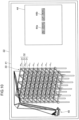
Fig. 4 is an illustration of an example modeldisplay screen image 41 displayed on thedisplay part 22 by the modeldisplay control part 111. The modeldisplay control part 111 causes thedisplay part 22 to display thebuilding model 30 corresponding to the building and having the three-dimensional shape in a three-dimensional virtual space displayed in the modeldisplay screen image 41 by using the information about thebuilding model 30 stored in thebuilding storage part 2. The modeldisplay control part 111 further causes thedisplay part 22 to display thecrane model 40 corresponding to thecrane 50 in the three-dimensional virtual space displayed in the modeldisplay screen image 41 by using the information about thecrane model 40 stored in thecrane storage part 3. Thebuilding model 30 illustrated inFig. 4 includes acomponent model 31 corresponding to a component constituting the building. Besides, thebuilding model 30 includes acomponent model group 32 including a plurality ofcomponent models 31. - The
information acquisition part 12 has a componentinformation acquisition part 121 or first acquisition part that acquires, from thebuilding storage part 2, information about onecomponent model 31 designated from thecomponent model group 32 that constitutes thebuilding model 30 displayed on thedisplay part 22. Examples of the designation of the onecomponent model 31 from thecomponent model group 32 may include clicking the onecomponent model 31 by a mouse serving as an example of themanipulation part 23. Alternatively, in a case where themanipulation part 23 includes a touch screen, the designation may be made by touching the onecomponent model 31 -
Fig. 5 is an illustration of an example state where the onecomponent model 31 is designated. When the user designates the onecomponent model 31 constituting thebuilding model 30 on the modeldisplay screen image 41 displayed by the modeldisplay control part 111, the modeldisplay control part 111 displays the designated onecomponent model 31 in a highlighted manner. InFig. 5 , the designatedcomponent model 31 is filled in black. - The
information acquisition part 12 further has a craneinformation acquisition part 122 or second acquisition part that acquires, from thecrane storage part 3, the information about thecrane 50 corresponding to thecrane model 40 arranged in the vicinity of thebuilding model 30 as displayed on thedisplay part 22. - The
calculation part 13 has thecrane calculation part 131 that calculates a value related to thecrane 50, such as a posture of thecrane 50, on the basis of the information acquired by theinformation acquisition part 12, and the ground contactpressure calculation part 132 that calculates the ground contact pressure acting to the ground on which thecrane 50 is supported. For instance, thecalculation part 13 enables a calculation when the user designates the onecomponent model 31 constituting thebuilding model 30 on the modeldisplay screen image 41 displayed by the modeldisplay control part 111. - The
crane calculation part 131 calculates, on the basis of the information about the onecomponent model 31 acquired by the componentinformation acquisition part 121 and the information about thecrane 50 acquired by the craneinformation acquisition part 122, values related to thecrane 50 including the posture of thecrane 50 and a load factor therefor in attachment of a component (hereinafter, referred to as a "target component" as well) corresponding to the onecomponent model 31 by thecrane 50. - The ground contact
pressure calculation part 132 has an attachingcalculation part 132a that calculates an attaching-time ground contact pressure acting in attachment of the target component by hoisting and lowering the target component, and a risingcalculation part 132b that calculates a rising-time ground contact pressure acting in rising of the crane. Each ground contact pressure is calculatable in accordance with a certain standard, such as JIS A8509, or other standard. Alternatively, another calculation way may be employed. As illustrated inFig. 4 , thebuilding model 30 includes acomponent model 31 located closer to thecrane 50 and anothercomponent model 31 located away from thecrane 50. Thecomponent models 31 are located at various heights from the ground surface. This means that attaching-time ground contact pressures acting to the ground differ from each other in hoisting of components respectively corresponding to thecomponent models 31 constituting thebuilding model 30 illustrated inFig. 4 by thecrane 50. In this respect, a grasp of each ground contact pressure before an actual work is important. - The attaching
calculation part 132a calculates ground contact pressures respectively applied at four points of a front end A and a rear end B of aleft crawler 61L (seeFig. 8 ) and a front end C and a rear end D of aright crawler 61R (seeFig. 8 ) when thecrane 50 comes to the posture of hoisting the target component corresponding to the onecomponent model 31 acquired by the componentinformation acquisition part 121. - The attaching
calculation part 132a further calculates a length L1 (seeFig. 8 ) associated with a load resulting from pressing by theleft crawler 61L and a length L2 (seeFig. 8 ) associated with a load resulting from pressing by theright crawler 61R. The attachingcalculation part 132a calculates a maximum ground contact pressure and a slewing angle under the maximum ground contact pressure when the slewingbody 70 slews at 360° in the posture or state of hoisting the target component. - For instance, the attaching
calculation part 132a calculates the ground contact pressure by a known way with at least any one of the posture of thecrane 50, the length of theboom 80, the length of thejib 90, the weight of thehook 93, the weight of thecounterweight 72, an angle of theboom 80, an angle of thejib 90, a working radius, a hoisted load (excluding the weight of the hook 93), the total weight of the crane 50 (excluding the hoisted load), and the slewing angle of the slewingbody 70. Examples of the posture of thecrane 50 include a luffing tower hoisting posture, a crawler crane hoisting posture, a tower crane hoisting posture. - The rising
calculation part 132b calculates a rising-time ground contact pressure acting in rising. Concerning the rising, when the slewingbody 70 has a slewing angle of 0°, theboom 80 and thejib 90 maximally extend and thejib 90 is closed to be located under theboom 80. For instance, theboom 80 and thejib 90 come into this state when assembled to the slewingbody 70. Specifically, two ways for rising or standing of thecrane 50 including thejib 90 and theboom 80 will be described below. The first way is called an inward holding way of causing theboom 80 to rise while holding thejib 90 from the state where thejib 90 is located under theboom 80. The second way is called an extraction way of causing thejib 90 to open and extend to align with theboom 80 and causing both theboom 80 and thejib 90 to stand from a state where the boom and the jib lie along the ground. Basically, in each way, thecrane 50 returns from a working posture to an original state preceding to rising when theboom 80 and thejib 90 are lowered. That is to say, a ground contact pressure acts to the ground in each of the rising and the lowering in the same manner. However, the ground contact pressure in one of the ways may be higher than the ground contact pressure in the other of the ways depending on a specification of a crane. Further, in each of the ways, the ground contact pressure in rising is likely to be higher than the ground contact pressure in normal working. From these perspectives, a grasp of a rising-time ground contact pressure in advance is important. -
Fig. 6 is an illustration of an example craneinformation screen image 42 displayed on thedisplay part 22 by the cranedisplay control part 112. The cranedisplay control part 112 causes thedisplay part 22 to display a result of a calculation by thecrane calculation part 131. For instance, as illustrated inFig. 6 , the cranedisplay control part 112 displays, in the craneinformation screen image 42, respective values of the length of theboom 80, the length of thejib 90, an angle of theboom 80, an angle of thejib 90, a working radius, a slewing angle of the slewingbody 70, a load factor, and a ground contact pressure together with their units. For example, the unit of the length is "m", the unit of the ground contact pressure is "t/m2", and the unit of the angle is "°". - The crane
display control part 112 further displays atransition button 42a given with the words "ground contact pressure details" in the craneinformation screen image 42. In the example illustrated inFig. 6 , the cranedisplay control part 112 displays thetransition button 42a near the value of the ground contact pressure at a lower right end in the craneinformation screen image 42. -
Fig. 7 is an illustration of an example relation between the modeldisplay screen image 41 and the craneinformation screen image 42. As illustrated inFig. 7 , for example, the cranedisplay control part 112 displays the craneinformation screen image 42 by superimposing the image on the modeldisplay screen image 41 displayed by the modeldisplay control part 111. This allows the user to easily repeat designation of acertain component model 31 and confirmation of a relevant ground contact pressure. Specifically, first, the user designates onecomponent model 31 with reference to thebuilding model 30 displayed in the modeldisplay screen image 41 and confirms a ground contact pressure in attachment of the onecomponent model 31, and thereafter designates anothercomponent model 31 and confirm a ground contact pressure in attachment of the anothercomponent model 31. - The crane
display control part 112 may display the craneinformation screen image 42 and the modeldisplay screen image 41 displayed by the modeldisplay control part 111 next to each other. In other words, the modeldisplay control part 111 may display the modeldisplay screen image 41 in a left display region on thedisplay part 22, and the cranedisplay control part 112 may display the craneinformation screen image 42 in a right display region on thedisplay part 22. -
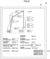
Fig. 8 is an illustration of an example ground contact pressuredetail screen image 43 displayed on thedisplay part 22 by the ground contact pressuredisplay control part 113. The ground contact pressuredisplay control part 113 causes thedisplay part 22 to display the ground contact pressuredetail screen image 43 in response to pressing of thetransition button 42a on the crane information screen image 42 (e.g., in response to clicking by a mouse serving as an example of the manipulation part 23). - As illustrated in
Fig. 8 , the ground contact pressuredisplay control part 113 displays, in the ground contact pressuredetail screen image 43, respective values of ground contact pressures at the four points of the front end A, the rear end B, the front end C, and the rear end D4 in a present posture, as calculated by the attachingcalculation part 132a, together with the unit "t/m2" for each ground contact pressure. The ground contact pressuredisplay control part 113 further displays, in the ground contact pressuredetail screen image 43, the length L1 associated with the load resulting from pressing by theleft crawler 61L and the length L2 associated with the load resulting from pressing by theright crawler 61R together with the unit "m" of each length, the lengths being calculated by the attachingcalculation part 132a. - The ground contact pressure
display control part 113 displays, in the ground contact pressuredetail screen image 43, a schematic diagram of the travelingbody 60 and the slewingbody 70 in a top view of thecrane 50 in a present posture, and a distribution (e.g., a trapezoidal distribution or a triangular distribution) of ground contact pressures related to the travelingbody 60. This enables visual recognition of a slewing angle θ of the slewingbody 70 and the distribution of the ground contact pressures in the present posture. - The ground contact pressure
display control part 113 further displays, in the ground contact pressuredetail screen image 43, a value of a maximum ground contact pressure at 360° being a maximum ground contact pressure calculated by the attachingcalculation part 132a when the slewingbody 70 slews at 360° and a slewing angle under the maximum ground contact pressure together with their respective units "t/m2" or "t/m2" and "°" or "degrees". - The ground contact pressure
display control part 113 displays, in the ground contact pressuredetail screen image 43, a value of a rising-time ground contact pressure calculated by the risingcalculation part 132b together with the unit "t/m2" or "t/m2". - The ground contact pressure
display control part 113 causes the display part to display, in the ground contact pressuredetail screen image 43, a permissible ground contact pressure input in advance together with the unit "t/m2" or "t/m2". In absence of the permissible ground contact pressure, "0" is displayed as the permissible ground contact pressure. - In presence of the permissible ground contact put in advance, the ground contact pressure
display control part 113 is configured to issue an alert when any of the values of the ground contact pressures at the four points of the front end A, the rear end B, the front end C, and the rear end D, the value of the maximum ground contact pressure at 360°, and the value of the rising-time ground contact pressure exceeds the permissible ground contact pressure. Example ways of issuing the alert include a way of expressing characters of the value of the ground contact pressure exceeding the permissible ground contact pressure in red and a way of showing a background of the characters of the value of the ground contact pressure exceeding the permissible ground contact pressure in red. - As described heretofore, the construction
planning assistance system 1 includes the component information acquisition part 121 (serving an example of the first acquisition part) that acquires information about onecomponent model 31 designated from thecomponent model group 32 that constitutes thebuilding model 30 corresponding to the building, having the three-dimensional shape, and displayed in the three-dimensional virtual space. The constructionplanning assistance system 1 further includes the crane information acquisition part 122 (serving as an example of the second acquisition part) that acquires information about thecrane 50 arranged in the vicinity of the building for hoisting a component constituting the building. Besides, the constructionplanning assistance system 1 includes the attachingcalculation part 132a that calculates, on the basis of the information about the onecomponent model 31 acquired by the componentinformation acquisition part 121 and the information about thecrane 50 acquired by the craneinformation acquisition part 122, an attaching-time ground contact pressure being a ground contact pressure acting to the ground where thecrane 50 is arranged in attachment of one component corresponding to the onecomponent model 31 by thecrane 50. Furthermore, the constructionplanning assistance system 1 includes the ground contact pressuredisplay control part 113 that causes thedisplay part 22 to display the attaching-time ground contact pressure calculated by the attachingcalculation part 132a. - The construction
planning assistance system 1 having this configuration enables the user to designate onecomponent model 31 from thecomponent model group 32 that constitutes thebuilding model 30 having the three-dimensional shape and then confirm, on thedisplay part 22, a ground contact pressure in attachment of one component corresponding to the designated onecomponent model 31. The configuration thus allows the user to easily grasp a ground contact pressure required for determination as to whether to protect the ground to support thecrane 50 thereon. This consequently enables easy determination on the necessity or unnecessity of protection of the ground to support the crane thereon. - Here, the attaching
calculation part 132a calculates a maximum ground contact pressure when thecrane 50 slews at 360° in a state of hoisting the one component. The ground contact pressuredisplay control part 113 causes thedisplay part 22 to display the maximum ground contact pressure. This configuration allows the user to easily grasp ground contact pressures in a plurality of states where the ground contact pressures are likely to be higher. This consequently enables determination on the necessity or unnecessity of protection of the ground for the support with high accuracy. - The construction
planning assistance system 1 further includes the risingcalculation part 132b that calculates a rising-time ground contact pressure acting to the ground in rising of thecrane 50. The ground contact pressuredisplay control part 113 causes thedisplay part 22 to display the rising-time ground contact pressure calculated by the risingcalculation part 132b. This configuration allows the user to easily grasp the rising-time ground contact pressure which is likely to be higher than the attaching-time ground contact pressure. This consequently enables determination on the necessity or unnecessity of protection of the ground for the support with high accuracy. - The ground contact pressure
display control part 113 is configured to issue an alert when the attaching-time ground contact pressure calculated by the attachingcalculation part 132a has a value exceeding a predetermined permissible ground contact pressure (serving as an example of the threshold). The ground contact pressuredisplay control part 113 is further configured to issue an alert when the rising-time ground contact pressure calculated by the risingcalculation part 132b has a value exceeding the predetermined permissible ground contact pressure (serving as an example of the threshold). This configuration allows the user to easily understand that the ground contact pressure becomes higher as the ground contact pressure exceeds the permissible ground contact pressure. - The construction
planning assistance system 1 is connected to thebuilding storage part 2 and thecrane storage part 3 via thenetwork 5 to acquire the information about the building and the information about thecrane 50 via thenetwork 5, but the acquisition way is not particularly limited thereto. Instead, thestorage part 21 may store the information stored in the building storage part and the information stored in thecrane storage part 3, and thecontroller 10 may acquire the information about the building and the information about thecrane 50 from thestorage part 21. - Software and hardware resources cooperatively achieve execution of the process by the
controller 10 in the constructionplanning assistance system 1 having the configuration described above. This enables the CPU10a in thecontroller 10 to execute a program for each operational part of thecontroller 10 to thereby make the operational part come into effect. For instance, thecontroller 10 may be provided with a non-transitory computer readable recording medium that records a program, and the CPU10a may read out the program stored in the recording medium. In this case, the program itself read out of the recording-medium makes each operational part in the embodiment described above come into effect, and the program itself and the recording medium that records the program result in constituting the present invention. Examples of the recording medium that provides such a program include a flexible disk, a CD-ROM, a DVD-ROM, a hard disk, an optical disc, an optical magnet disc, a CD-R, a magnetic tape, a non-volatile memory card, and a ROM. The constructionplanning assistance system 1 may download the program via thenetwork 5. - In addition, a program constituting the present invention includes causing a computer to execute: first acquisition of acquiring information about one
component model 31 designated from acomponent model group 32 that constitutes abuilding model 30 corresponding to a building, having a three-dimensional shape, and displayed in a three-dimensional virtual space; and second acquisition of acquiring information about acrane 50 arranged in the vicinity of the building for hoisting a component constituting the building. The program constituting the present invention further includes causing the computer to execute: attaching calculation of calculating, on the basis of the information about the onecomponent model 31 acquired in the first acquisition and the information about thecrane 50 acquired in the second acquisition, an attaching-time ground contact pressure being a ground contact pressure acting to ground where thecrane 50 is arranged in attachment of one component corresponding to the onecomponent model 31 by thecrane 50; and displaying of causing thedisplay part 22 to display the attaching-time ground contact pressure calculated in the attaching calculation. -
Fig. 9 is a block diagram showing example operational parts of a constructionplanning assistance system 200 according to a second embodiment. The constructionplanning assistance system 200 according to the second embodiment differs from the constructionplanning assistance system 1 according to the first embodiment in acontroller 210 corresponding to thecontroller 10. Hereinafter, the differences from the first embodiment will be described. Here, the same constituent elements and configurations in the second embodiment as those in the first embodiment will be given the same reference numerals or signs, and detailed descriptions therefor will be omitted. - The
controller 210 includes a crane display control part 212 corresponding to the cranedisplay control part 112 in the first embodiment, and a component information acquisition part 221 or third acquisition part corresponding to the componentinformation acquisition part 121 in the first embodiment. -
Fig. 10 is an illustration of an example componentdesignation screen image 44 displayed on adisplay part 22 by the crane display control part 212. The crane display control part 212 may display the componentdesignation screen image 44 illustrated inFig. 10 by superimposing the image on a modeldisplay screen image 41 displayed by a modeldisplay control part 111. The componentdesignation screen image 44 shows anacceptance button 44a given with the words "single component model designation" to accept designation of onecomponent model 31 by a user, and anacceptance button 44b given with the words "plural component models designation" to accept designation of a plurality ofcomponent models 31 by the user. The crane display control part 212 may display the componentdesignation screen image 44 and the modeldisplay screen image 41 next to each other. - When one
component model 31 is designated from acomponent model group 32 that constitutes abuilding model 30 displayed in the modeldisplay screen image 41 on the display part 22 (e.g., when one component model is clicked by the mouse serving as an example of the manipulation part 23), the modeldisplay control part 111 displays the designatedcomponent model 31 in a highlighted manner. The component information acquisition part 221 then acquires information about the onecomponent model 31 from abuilding storage part 2 in response to pressing of theacceptance button 44a (e.g., in response to clicking by a mouse serving as the manipulation part 23) in a state where the onecomponent model 31 is designated. -
Fig. 11 is an illustration of an example state where a plurality ofcomponent models 31 is designated, and theacceptance button 44b is pressed. When thecomponent models 31 are designated from thecomponent model group 32 that constitutes thebuilding model 30 displayed in the modeldisplay screen image 41 on thedisplay part 22, the modeldisplay control part 111 displays the designatedcomponent models 31 in a highlighted manner as illustrated inFig. 11 . The component information acquisition part 221 then acquires information about thecomponent models 31 from thebuilding storage part 2 in response to pressing of theacceptance button 44b in a state where thecomponent models 31 are designated. - A
crane calculation part 131 calculates, on the basis of the information about the onecomponent model 31 or thecomponent models 31 acquired by the component information acquisition part 221 and the information about thecrane 50 acquired by the craneinformation acquisition part 122, values related to thecrane 50, such as the posture of thecrane 50 and a load factor therefor, in attachment of a component corresponding to the onecomponent model 31 or components corresponding to thecomponent models 31 by thecrane 50. -
Fig. 12 is a table showing an example craneinformation screen image 45 displayed on thedisplay part 22 by the crane display control part 212. The crane display control part 212 causes thedisplay part 22 to display a result of a calculation by thecrane calculation part 131. The crane display control part 212 displays, in the craneinformation screen image 45, respective values of a length of aboom 80, a length of ajib 90, an angle of theboom 80, an angle of thejib 90, a working radius, a slewing angle of a slewingbody 70, a load factor, and an attaching-time ground contact pressure per designatedcomponent model 31. - In the example illustrated in
Fig. 12 , the crane display control part 212 displays the attaching-time ground contact pressure and other information percomponent model 31 in a list. Specifically, the crane display control part displays identification information about the designatedcomponent models 31 in a column in a vertical direction in the craneinformation screen image 45 and displays results of calculations for the length of theboom 80, an attaching-time ground contact pressure, and other parameters percomponent model 31 in a row in a horizontal direction in the screen image. -
Fig. 13 is an illustration of an example state where onecomponent model 31 is designated from thecomponent models 31. When a specific row showing the onecomponent model 31 is selected from the list (e.g., when the row is clicked by a mouse serving as an example of the manipulation part 23) in the craneinformation screen image 45, the modeldisplay control part 111 displays the selectedcomponent model 31 in a highlighted manner (inFig. 13 , the selectedcomponent model 31 is filled in black). For instance, this configuration allows the user to grasp acomponent model 31 requiring the highest attaching-time ground contact pressure among a plurality of designatedcomponent models 31. - When a specific row showing one
component model 31 is designated from the list in the crane information screen image 45 (e.g., when the row is double-clicked by a mouse serving as an example of the manipulation part 23), the ground contact pressuredisplay control part 113 may cause thedisplay part 22 to display a ground contact pressuredetail screen image 43 about the onecomponent model 31. For instance, this configuration allows the user to grasp a maximum ground contact pressure at 360° constituting detail information about a ground contact pressure for acomponent model 31 requiring the highest attaching-time ground contact pressure among a plurality of designatedcomponent models 31. - As described heretofore, the construction
planning assistance system 200 includes the component information acquisition part 221 (serving as an example of the third acquisition part) that acquires information about a plurality ofcomponent models 31 designated from thecomponent model group 32. An attachingcalculation part 132a calculates, on the basis of the information about thecomponent models 31 acquired by the component information acquisition part 221 and the information about thecrane 50 acquired by the craneinformation acquisition part 122, attaching-time ground contact pressures in attachment of a plurality of components respectively corresponding to thecomponent models 31 by thecrane 50. The crane display control part 212 causes thedisplay part 22 to display the attaching-time ground contact pressures calculated by the attachingcalculation part 132a. - The construction
planning assistance system 200 having this configuration enables the user to designate a plurality ofcomponent models 31 from thecomponent model group 32 that constitutes thebuilding model 30 having the three-dimensional shape and then confirm, on thedisplay part 22, ground contact pressures in attachment of a plurality of components respectively corresponding to the designatedcomponent models 31. The configuration thus allows the user to easily grasp a ground contact pressure required for determination as to whether to protect the ground to support thecrane 50 thereon. This consequently enables easy determination on the necessity or unnecessity of protection of the ground to support the crane thereon. - In addition, a program constituting the present invention is a program that includes causing a computer to execute third acquisition of acquiring information about a plurality of
component models 31 from thecomponent model group 32. In the program constituting the present invention, the attaching calculation includes calculating, on the basis of the information about thecomponent models 31 acquired in the third acquisition and the information about thecrane 50 acquired in the second acquisition, attaching-time ground contact pressures in attachment of a plurality of components respectively corresponding to thecomponent models 31 by thecrane 50. Display controlling includes causing thedisplay part 22 to display the attaching-time ground contact pressures calculated in the attaching calculation. - The present invention provides a construction planning assistance system. The construction planning assistance system includes: a first acquisition part that acquires information about at least one component model designated from a component model group that constitutes a building model corresponding to a building, having a three-dimensional shape, and displayed in a three-dimensional virtual space; a second acquisition part that acquires information about a crane arranged in the vicinity of the building for hoisting a component constituting the building; an attaching calculation part that calculates, on the basis of the information about the at least one component model acquired by the first acquisition part and the information about the crane acquired by the second acquisition part, an attaching-time ground contact pressure being a ground contact pressure acting to ground where the crane is arranged in attachment of at least one component corresponding to the at least component model by the crane; and a display control part that causes a display part to display the attaching-time ground contact pressure calculated by the attaching calculation part.
- In the construction planning assistance system, the attaching calculation part may calculate a maximum ground contact pressure when the crane slews at 360° in a state of hoisting the at least one member, and the display control part may cause the display part to display the maximum ground contact pressure.
- The construction planning assistance system may further include a rising calculation part that calculates a rising-time ground contact pressure being a ground contact pressure acting to the ground in rising of the crane. The display control part may cause the display part to display the rising-time ground contact pressure calculated by the rising calculation part.
- In the construction planning assistance system, the display control part may be configured to issue an alert when the attaching-time ground contact pressure calculated by the attaching calculation part has a value exceeding a predetermined threshold.
- In the construction planning assistance system, the display control part may be configured to issue an alert when the rising-time ground contact pressure calculated by the rising calculation part has a value exceeding a predetermined threshold.
- In the construction planning assistance system, the first acquisition part may be configured to acquire information about a plurality of the component models designated from the component model group. The attaching calculation part may calculate, on the basis of the information about the component models acquired by the first acquisition part and the information about the crane acquired by the second acquisition part, attaching-time ground contact pressures in attachment of a plurality of components respectively corresponding to the component models by the crane. The display control part may cause the display part to display the attaching-time ground contact pressures calculated by the attaching calculation part.
- The present invention further provides a program that includes causing a computer to execute predetermined operations. The predetermined operations include: first acquisition of acquiring information about at least one component model designated from a component model group that constitutes a building model corresponding to a building, having a three-dimensional shape, and displayed in a three-dimensional virtual space; second acquisition of acquiring information about a crane arranged in the vicinity of the building for hoisting a component constituting the building; attaching calculation of calculating, on the basis of the information about the at least one component model acquired in the first acquisition and the information about the crane acquired in the second acquisition, an attaching-time ground contact pressure being a ground contact pressure acting to ground where the crane is arranged in attachment of at least one component corresponding to the at least one component model by the crane; and displaying of causing a display part to display the attaching-time ground contact pressure calculated in the attaching calculation.
- In the program, the computer may be further caused to execute: in the first acquisition, acquiring information about a plurality of the component models designated from the component model group; in the attaching calculation, calculating, on the basis of the information about the component models acquired in the first acquisition and the information about the crane acquired in the second acquisition, attaching-time ground contact pressures in attachment of a plurality of components respectively corresponding to the component models by the crane; and in the displaying, causing the display part to display the attaching-time ground contact pressures calculated in the attaching calculation.
- The present invention provides a construction planning assistance system or other system that enables an easy grasp of a ground contact pressure required for determination as to whether to protect ground.
Claims (8)
- A construction planning assistance system, comprising:a first acquisition part that acquires information about at least one component model designated from a component model group that constitutes a building model corresponding to a building, having a three-dimensional shape, and displayed in a three-dimensional virtual space;a second acquisition part that acquires information about a crane arranged in the vicinity of the building for hoisting a component constituting the building;an attaching calculation part that calculates, on the basis of the information about the at least one component model acquired by the first acquisition part and the information about the crane acquired by the second acquisition part, an attaching-time ground contact pressure being a ground contact pressure acting to ground where the crane is arranged in attachment of at least one component corresponding to the at least component model by the crane; anda display control part that causes a display part to display the attaching-time ground contact pressure calculated by the attaching calculation part.
- The construction planning assistance system according to claim 1, wherein the attaching calculation part calculates a maximum ground contact pressure when the crane slews at 360° in a state of hoisting the at least one member, and
the display control part causes the display part to display the maximum ground contact pressure. - The construction planning assistance system according to claim 1, further comprising a rising calculation part that calculates a rising-time ground contact pressure being a ground contact pressure acting to the ground in rising of the crane, wherein
the display control part causes the display part to display the rising-time ground contact pressure calculated by the rising calculation part. - The construction planning assistance system according to claim 1, wherein the display control part is configured to issue an alert when the attaching-time ground contact pressure calculated by the attaching calculation part has a value exceeding a predetermined threshold.
- The construction planning assistance system according to claim 3, wherein the display control part is configured to issue an alert when the rising-time ground contact pressure calculated by the rising calculation part has a value exceeding a predetermined threshold.
- The construction planning assistance system according to claim 1, wherein the first acquisition part is configured to acquire information about a plurality of the component models designated from the component model group,the attaching calculation part calculates, on the basis of the information about the component models acquired by the first acquisition part and the information about the crane acquired by the second acquisition part, attaching-time ground contact pressures in attachment of a plurality of components respectively corresponding to the component models by the crane, andthe display control part causes the display part to display the attaching-time ground contact pressures calculated by the attaching calculation part.
- A program, comprising:
causing a computer to execute:first acquisition of acquiring information about at least one component model designated from a component model group that constitutes a building model corresponding to a building, having a three-dimensional shape, and displayed in a three-dimensional virtual space;second acquisition of acquiring information about a crane arranged in the vicinity of the building for hoisting a component constituting the building;attaching calculation of calculating, on the basis of the information about the at least one component model acquired in the first acquisition and the information about the crane acquired in the second acquisition, an attaching-time ground contact pressure being a ground contact pressure acting to ground where the crane is arranged in attachment of at least one component corresponding to the at least one component model by the crane; anddisplaying of causing a display part to display the attaching-time ground contact pressure calculated in the attaching calculation. - The program according to claim 7, wherein the computer is caused to execute:in the first acquisition, acquiring information about a plurality of the component models designated from the component model group;in the attaching calculation, calculating, on the basis of the information about the component models acquired in the first acquisition and the information about the crane acquired in the second acquisition, attaching-time ground contact pressures in attachment of a plurality of components respectively corresponding to the component models by the crane; andin the displaying, causing the display part to display the attaching-time ground contact pressures calculated in the attaching calculation.
Applications Claiming Priority (2)
| Application Number | Priority Date | Filing Date | Title |
|---|---|---|---|
| JP2022158907A JP7464094B1 (en) | 2022-09-30 | 2022-09-30 | Construction planning support device and program |
| PCT/JP2023/031888 WO2024070486A1 (en) | 2022-09-30 | 2023-08-31 | Construction planning assistance device and program |
Publications (2)
| Publication Number | Publication Date |
|---|---|
| EP4578813A1 true EP4578813A1 (en) | 2025-07-02 |
| EP4578813A4 EP4578813A4 (en) | 2025-12-31 |
Family
ID=90477258
Family Applications (1)
| Application Number | Title | Priority Date | Filing Date |
|---|---|---|---|
| EP23871726.8A Pending EP4578813A4 (en) | 2022-09-30 | 2023-08-31 | AID AND PROGRAM FOR BUILDING PLANNING |
Country Status (4)
| Country | Link |
|---|---|
| US (1) | US20260105202A1 (en) |
| EP (1) | EP4578813A4 (en) |
| JP (1) | JP7464094B1 (en) |
| WO (1) | WO2024070486A1 (en) |
Family Cites Families (5)
| Publication number | Priority date | Publication date | Assignee | Title |
|---|---|---|---|---|
| JP2516272B2 (en) * | 1990-06-07 | 1996-07-24 | 株式会社日立製作所 | Mobile crane operation plan creation support device |
| JP2003081580A (en) * | 2001-09-14 | 2003-03-19 | Hitachi Plant Eng & Constr Co Ltd | Crane simulator |
| DE102006027202A1 (en) | 2006-06-12 | 2007-12-13 | Liebherr-Werk Nenzing Gmbh, Nenzing | Crane e.g. crawler crane, operation planner, has central planning unit performing simulation and calculation of operation, and clients inputting and outputting data and communicating with central planning unit by Internet |
| KR100864872B1 (en) * | 2007-01-08 | 2008-10-22 | 삼성물산 주식회사 | How to review the safety of mobile crane |
| US12208996B2 (en) | 2018-08-02 | 2025-01-28 | Tadano Ltd. | Operation assistance module, image generation application, and work machine |
-
2022
- 2022-09-30 JP JP2022158907A patent/JP7464094B1/en active Active
-
2023
- 2023-08-31 US US19/115,440 patent/US20260105202A1/en active Pending
- 2023-08-31 EP EP23871726.8A patent/EP4578813A4/en active Pending
- 2023-08-31 WO PCT/JP2023/031888 patent/WO2024070486A1/en not_active Ceased
Also Published As
| Publication number | Publication date |
|---|---|
| JP2024054437A (en) | 2024-04-17 |
| EP4578813A4 (en) | 2025-12-31 |
| JP7464094B1 (en) | 2024-04-09 |
| WO2024070486A1 (en) | 2024-04-04 |
| US20260105202A1 (en) | 2026-04-16 |
Similar Documents
| Publication | Publication Date | Title |
|---|---|---|
| JP7396282B2 (en) | Operation support module, image generation application, and work equipment | |
| US9079756B2 (en) | Elevating platform and a method of controlling such a platform | |
| KR101595243B1 (en) | Automatic modeling system for facility in field based building information modeling and method thereof | |
| US9227821B1 (en) | Crane operation simulation | |
| US8275591B2 (en) | Crane planner | |
| JP7434296B2 (en) | Crane inspection system and crane | |
| WO2013006625A2 (en) | Crane maneuvering assistance | |
| JP2014031223A (en) | Work range figure, and device for displaying the same | |
| JP2017186163A (en) | Crane work auxiliary device | |
| JP2021042045A (en) | Simulation device | |
| US9016487B2 (en) | Crane apparatus | |
| CN114772466A (en) | Crane stability analysis method, crane anti-overturning control method and device | |
| JP2021022020A (en) | Crane planning support system | |
| US20260105202A1 (en) | Construction planning assistance device and program | |
| JP7676750B2 (en) | Crane model selection system | |
| JP2024123271A (en) | Information Acquisition System | |
| JP2025061351A (en) | Crane Inspection System | |
| JPH0441390A (en) | Mobile crane operation planning support device | |
| US20190241407A1 (en) | Suspended load calculation device | |
| EP3694804A1 (en) | A predictive stability control method and system for truck-mounted cranes | |
| EP4693255A1 (en) | Work simulator, work simulation program, and work simulation method | |
| JP7639350B2 (en) | Lifting support system, lifting support method, and lifting support program | |
| JP3976361B2 (en) | Heavy equipment work plan creation support device | |
| JP4735002B2 (en) | Rooftop thermal storage stand planning support program | |
| JP7533132B2 (en) | Crane deformation estimation system |
Legal Events
| Date | Code | Title | Description |
|---|---|---|---|
| STAA | Information on the status of an ep patent application or granted ep patent |
Free format text: STATUS: THE INTERNATIONAL PUBLICATION HAS BEEN MADE |
|
| PUAI | Public reference made under article 153(3) epc to a published international application that has entered the european phase |
Free format text: ORIGINAL CODE: 0009012 |
|
| STAA | Information on the status of an ep patent application or granted ep patent |
Free format text: STATUS: REQUEST FOR EXAMINATION WAS MADE |
|
| 17P | Request for examination filed |
Effective date: 20250328 |
|
| AK | Designated contracting states |
Kind code of ref document: A1 Designated state(s): AL AT BE BG CH CY CZ DE DK EE ES FI FR GB GR HR HU IE IS IT LI LT LU LV MC ME MK MT NL NO PL PT RO RS SE SI SK SM TR |
|
| A4 | Supplementary search report drawn up and despatched |
Effective date: 20251127 |
|
| RIC1 | Information provided on ipc code assigned before grant |
Ipc: B66C 13/16 20060101AFI20251121BHEP Ipc: B66C 23/88 20060101ALI20251121BHEP Ipc: G06F 30/13 20200101ALI20251121BHEP Ipc: G06F 30/20 20200101ALI20251121BHEP Ipc: B66C 23/90 20060101ALI20251121BHEP Ipc: G06F 3/0482 20130101ALI20251121BHEP Ipc: G06F 3/04842 20220101ALI20251121BHEP Ipc: G06F 119/14 20200101ALN20251121BHEP |
|
| DAV | Request for validation of the european patent (deleted) | ||
| DAX | Request for extension of the european patent (deleted) |