EP4578715A1 - Charger - Google Patents
Charger Download PDFInfo
- Publication number
- EP4578715A1 EP4578715A1 EP23931058.4A EP23931058A EP4578715A1 EP 4578715 A1 EP4578715 A1 EP 4578715A1 EP 23931058 A EP23931058 A EP 23931058A EP 4578715 A1 EP4578715 A1 EP 4578715A1
- Authority
- EP
- European Patent Office
- Prior art keywords
- moving pulley
- charger
- pulley
- cover
- roller
- Prior art date
- Legal status (The legal status is an assumption and is not a legal conclusion. Google has not performed a legal analysis and makes no representation as to the accuracy of the status listed.)
- Withdrawn
Links
Images






Classifications
-
- B—PERFORMING OPERATIONS; TRANSPORTING
- B60—VEHICLES IN GENERAL
- B60L—PROPULSION OF ELECTRICALLY-PROPELLED VEHICLES; SUPPLYING ELECTRIC POWER FOR AUXILIARY EQUIPMENT OF ELECTRICALLY-PROPELLED VEHICLES; ELECTRODYNAMIC BRAKE SYSTEMS FOR VEHICLES IN GENERAL; MAGNETIC SUSPENSION OR LEVITATION FOR VEHICLES; MONITORING OPERATING VARIABLES OF ELECTRICALLY-PROPELLED VEHICLES; ELECTRIC SAFETY DEVICES FOR ELECTRICALLY-PROPELLED VEHICLES
- B60L58/00—Methods or circuit arrangements for monitoring or controlling batteries or fuel cells, specially adapted for electric vehicles
- B60L58/10—Methods or circuit arrangements for monitoring or controlling batteries or fuel cells, specially adapted for electric vehicles for monitoring or controlling batteries
- B60L58/18—Methods or circuit arrangements for monitoring or controlling batteries or fuel cells, specially adapted for electric vehicles for monitoring or controlling batteries of two or more battery modules
-
- H—ELECTRICITY
- H02—GENERATION; CONVERSION OR DISTRIBUTION OF ELECTRIC POWER
- H02G—INSTALLATION OF ELECTRIC CABLES OR LINES, OR OF COMBINED OPTICAL AND ELECTRIC CABLES OR LINES
- H02G11/00—Arrangements of electric cables or lines between relatively-movable parts
- H02G11/003—Arrangements of electric cables or lines between relatively-movable parts using gravity-loaded or spring-loaded loop
-
- B—PERFORMING OPERATIONS; TRANSPORTING
- B60—VEHICLES IN GENERAL
- B60L—PROPULSION OF ELECTRICALLY-PROPELLED VEHICLES; SUPPLYING ELECTRIC POWER FOR AUXILIARY EQUIPMENT OF ELECTRICALLY-PROPELLED VEHICLES; ELECTRODYNAMIC BRAKE SYSTEMS FOR VEHICLES IN GENERAL; MAGNETIC SUSPENSION OR LEVITATION FOR VEHICLES; MONITORING OPERATING VARIABLES OF ELECTRICALLY-PROPELLED VEHICLES; ELECTRIC SAFETY DEVICES FOR ELECTRICALLY-PROPELLED VEHICLES
- B60L53/00—Methods of charging batteries, specially adapted for electric vehicles; Charging stations or on-board charging equipment therefor; Exchange of energy storage elements in electric vehicles
- B60L53/10—Methods of charging batteries, specially adapted for electric vehicles; Charging stations or on-board charging equipment therefor; Exchange of energy storage elements in electric vehicles characterised by the energy transfer between the charging station and the vehicle
- B60L53/14—Conductive energy transfer
-
- B—PERFORMING OPERATIONS; TRANSPORTING
- B60—VEHICLES IN GENERAL
- B60L—PROPULSION OF ELECTRICALLY-PROPELLED VEHICLES; SUPPLYING ELECTRIC POWER FOR AUXILIARY EQUIPMENT OF ELECTRICALLY-PROPELLED VEHICLES; ELECTRODYNAMIC BRAKE SYSTEMS FOR VEHICLES IN GENERAL; MAGNETIC SUSPENSION OR LEVITATION FOR VEHICLES; MONITORING OPERATING VARIABLES OF ELECTRICALLY-PROPELLED VEHICLES; ELECTRIC SAFETY DEVICES FOR ELECTRICALLY-PROPELLED VEHICLES
- B60L53/00—Methods of charging batteries, specially adapted for electric vehicles; Charging stations or on-board charging equipment therefor; Exchange of energy storage elements in electric vehicles
- B60L53/10—Methods of charging batteries, specially adapted for electric vehicles; Charging stations or on-board charging equipment therefor; Exchange of energy storage elements in electric vehicles characterised by the energy transfer between the charging station and the vehicle
- B60L53/14—Conductive energy transfer
- B60L53/16—Connectors, e.g. plugs or sockets, specially adapted for charging electric vehicles
-
- B—PERFORMING OPERATIONS; TRANSPORTING
- B60—VEHICLES IN GENERAL
- B60L—PROPULSION OF ELECTRICALLY-PROPELLED VEHICLES; SUPPLYING ELECTRIC POWER FOR AUXILIARY EQUIPMENT OF ELECTRICALLY-PROPELLED VEHICLES; ELECTRODYNAMIC BRAKE SYSTEMS FOR VEHICLES IN GENERAL; MAGNETIC SUSPENSION OR LEVITATION FOR VEHICLES; MONITORING OPERATING VARIABLES OF ELECTRICALLY-PROPELLED VEHICLES; ELECTRIC SAFETY DEVICES FOR ELECTRICALLY-PROPELLED VEHICLES
- B60L53/00—Methods of charging batteries, specially adapted for electric vehicles; Charging stations or on-board charging equipment therefor; Exchange of energy storage elements in electric vehicles
- B60L53/10—Methods of charging batteries, specially adapted for electric vehicles; Charging stations or on-board charging equipment therefor; Exchange of energy storage elements in electric vehicles characterised by the energy transfer between the charging station and the vehicle
- B60L53/14—Conductive energy transfer
- B60L53/18—Cables specially adapted for charging electric vehicles
-
- B—PERFORMING OPERATIONS; TRANSPORTING
- B60—VEHICLES IN GENERAL
- B60L—PROPULSION OF ELECTRICALLY-PROPELLED VEHICLES; SUPPLYING ELECTRIC POWER FOR AUXILIARY EQUIPMENT OF ELECTRICALLY-PROPELLED VEHICLES; ELECTRODYNAMIC BRAKE SYSTEMS FOR VEHICLES IN GENERAL; MAGNETIC SUSPENSION OR LEVITATION FOR VEHICLES; MONITORING OPERATING VARIABLES OF ELECTRICALLY-PROPELLED VEHICLES; ELECTRIC SAFETY DEVICES FOR ELECTRICALLY-PROPELLED VEHICLES
- B60L53/00—Methods of charging batteries, specially adapted for electric vehicles; Charging stations or on-board charging equipment therefor; Exchange of energy storage elements in electric vehicles
- B60L53/30—Constructional details of charging stations
-
- B—PERFORMING OPERATIONS; TRANSPORTING
- B60—VEHICLES IN GENERAL
- B60L—PROPULSION OF ELECTRICALLY-PROPELLED VEHICLES; SUPPLYING ELECTRIC POWER FOR AUXILIARY EQUIPMENT OF ELECTRICALLY-PROPELLED VEHICLES; ELECTRODYNAMIC BRAKE SYSTEMS FOR VEHICLES IN GENERAL; MAGNETIC SUSPENSION OR LEVITATION FOR VEHICLES; MONITORING OPERATING VARIABLES OF ELECTRICALLY-PROPELLED VEHICLES; ELECTRIC SAFETY DEVICES FOR ELECTRICALLY-PROPELLED VEHICLES
- B60L53/00—Methods of charging batteries, specially adapted for electric vehicles; Charging stations or on-board charging equipment therefor; Exchange of energy storage elements in electric vehicles
- B60L53/30—Constructional details of charging stations
- B60L53/31—Charging columns specially adapted for electric vehicles
-
- B—PERFORMING OPERATIONS; TRANSPORTING
- B65—CONVEYING; PACKING; STORING; HANDLING THIN OR FILAMENTARY MATERIAL
- B65H—HANDLING THIN OR FILAMENTARY MATERIAL, e.g. SHEETS, WEBS, CABLES
- B65H57/00—Guides for filamentary materials; Supports therefor
- B65H57/14—Pulleys, rollers, or rotary bars
-
- B—PERFORMING OPERATIONS; TRANSPORTING
- B65—CONVEYING; PACKING; STORING; HANDLING THIN OR FILAMENTARY MATERIAL
- B65H—HANDLING THIN OR FILAMENTARY MATERIAL, e.g. SHEETS, WEBS, CABLES
- B65H57/00—Guides for filamentary materials; Supports therefor
- B65H57/26—Supports for guides
-
- B—PERFORMING OPERATIONS; TRANSPORTING
- B65—CONVEYING; PACKING; STORING; HANDLING THIN OR FILAMENTARY MATERIAL
- B65H—HANDLING THIN OR FILAMENTARY MATERIAL, e.g. SHEETS, WEBS, CABLES
- B65H57/00—Guides for filamentary materials; Supports therefor
- B65H57/28—Reciprocating or oscillating guides
-
- F—MECHANICAL ENGINEERING; LIGHTING; HEATING; WEAPONS; BLASTING
- F16—ENGINEERING ELEMENTS AND UNITS; GENERAL MEASURES FOR PRODUCING AND MAINTAINING EFFECTIVE FUNCTIONING OF MACHINES OR INSTALLATIONS; THERMAL INSULATION IN GENERAL
- F16F—SPRINGS; SHOCK-ABSORBERS; MEANS FOR DAMPING VIBRATION
- F16F1/00—Springs
- F16F1/02—Springs made of steel or other material having low internal friction; Wound, torsion, leaf, cup, ring or the like springs, the material of the spring not being relevant
-
- F—MECHANICAL ENGINEERING; LIGHTING; HEATING; WEAPONS; BLASTING
- F16—ENGINEERING ELEMENTS AND UNITS; GENERAL MEASURES FOR PRODUCING AND MAINTAINING EFFECTIVE FUNCTIONING OF MACHINES OR INSTALLATIONS; THERMAL INSULATION IN GENERAL
- F16F—SPRINGS; SHOCK-ABSORBERS; MEANS FOR DAMPING VIBRATION
- F16F9/00—Springs, vibration-dampers, shock-absorbers, or similarly-constructed movement-dampers using a fluid or the equivalent as damping medium
- F16F9/02—Springs, vibration-dampers, shock-absorbers, or similarly-constructed movement-dampers using a fluid or the equivalent as damping medium using gas only or vacuum
- F16F9/0209—Telescopic
- F16F9/0218—Mono-tubular units
-
- H—ELECTRICITY
- H02—GENERATION; CONVERSION OR DISTRIBUTION OF ELECTRIC POWER
- H02G—INSTALLATION OF ELECTRIC CABLES OR LINES, OR OF COMBINED OPTICAL AND ELECTRIC CABLES OR LINES
- H02G11/00—Arrangements of electric cables or lines between relatively-movable parts
- H02G11/02—Arrangements of electric cables or lines between relatively-movable parts using take-up reel or drum
-
- H—ELECTRICITY
- H02—GENERATION; CONVERSION OR DISTRIBUTION OF ELECTRIC POWER
- H02J—ELECTRIC POWER NETWORKS; CIRCUIT ARRANGEMENTS OR SYSTEMS FOR SUPPLYING OR DISTRIBUTING ELECTRIC POWER; SYSTEMS FOR STORING ELECTRIC ENERGY
- H02J7/00—Circuit arrangements for charging or discharging batteries or for supplying loads from batteries
- H02J7/70—Circuit arrangements for charging or discharging batteries or for supplying loads from batteries characterised by the mechanical construction
-
- B—PERFORMING OPERATIONS; TRANSPORTING
- B60—VEHICLES IN GENERAL
- B60Y—INDEXING SCHEME RELATING TO ASPECTS CROSS-CUTTING VEHICLE TECHNOLOGY
- B60Y2200/00—Type of vehicle
- B60Y2200/90—Vehicles comprising electric prime movers
- B60Y2200/91—Electric vehicles
-
- B—PERFORMING OPERATIONS; TRANSPORTING
- B65—CONVEYING; PACKING; STORING; HANDLING THIN OR FILAMENTARY MATERIAL
- B65H—HANDLING THIN OR FILAMENTARY MATERIAL, e.g. SHEETS, WEBS, CABLES
- B65H2701/00—Handled material; Storage means
- B65H2701/30—Handled filamentary material
- B65H2701/34—Handled filamentary material electric cords or electric power cables
-
- F—MECHANICAL ENGINEERING; LIGHTING; HEATING; WEAPONS; BLASTING
- F16—ENGINEERING ELEMENTS AND UNITS; GENERAL MEASURES FOR PRODUCING AND MAINTAINING EFFECTIVE FUNCTIONING OF MACHINES OR INSTALLATIONS; THERMAL INSULATION IN GENERAL
- F16F—SPRINGS; SHOCK-ABSORBERS; MEANS FOR DAMPING VIBRATION
- F16F2222/00—Special physical effects, e.g. nature of damping effects
- F16F2222/12—Fluid damping
- F16F2222/126—Fluid damping using gases
-
- Y—GENERAL TAGGING OF NEW TECHNOLOGICAL DEVELOPMENTS; GENERAL TAGGING OF CROSS-SECTIONAL TECHNOLOGIES SPANNING OVER SEVERAL SECTIONS OF THE IPC; TECHNICAL SUBJECTS COVERED BY FORMER USPC CROSS-REFERENCE ART COLLECTIONS [XRACs] AND DIGESTS
- Y02—TECHNOLOGIES OR APPLICATIONS FOR MITIGATION OR ADAPTATION AGAINST CLIMATE CHANGE
- Y02T—CLIMATE CHANGE MITIGATION TECHNOLOGIES RELATED TO TRANSPORTATION
- Y02T10/00—Road transport of goods or passengers
- Y02T10/60—Other road transportation technologies with climate change mitigation effect
- Y02T10/70—Energy storage systems for electromobility, e.g. batteries
-
- Y—GENERAL TAGGING OF NEW TECHNOLOGICAL DEVELOPMENTS; GENERAL TAGGING OF CROSS-SECTIONAL TECHNOLOGIES SPANNING OVER SEVERAL SECTIONS OF THE IPC; TECHNICAL SUBJECTS COVERED BY FORMER USPC CROSS-REFERENCE ART COLLECTIONS [XRACs] AND DIGESTS
- Y02—TECHNOLOGIES OR APPLICATIONS FOR MITIGATION OR ADAPTATION AGAINST CLIMATE CHANGE
- Y02T—CLIMATE CHANGE MITIGATION TECHNOLOGIES RELATED TO TRANSPORTATION
- Y02T10/00—Road transport of goods or passengers
- Y02T10/60—Other road transportation technologies with climate change mitigation effect
- Y02T10/7072—Electromobility specific charging systems or methods for batteries, ultracapacitors, supercapacitors or double-layer capacitors
-
- Y—GENERAL TAGGING OF NEW TECHNOLOGICAL DEVELOPMENTS; GENERAL TAGGING OF CROSS-SECTIONAL TECHNOLOGIES SPANNING OVER SEVERAL SECTIONS OF THE IPC; TECHNICAL SUBJECTS COVERED BY FORMER USPC CROSS-REFERENCE ART COLLECTIONS [XRACs] AND DIGESTS
- Y02—TECHNOLOGIES OR APPLICATIONS FOR MITIGATION OR ADAPTATION AGAINST CLIMATE CHANGE
- Y02T—CLIMATE CHANGE MITIGATION TECHNOLOGIES RELATED TO TRANSPORTATION
- Y02T90/00—Enabling technologies or technologies with a potential or indirect contribution to GHG emissions mitigation
- Y02T90/10—Technologies relating to charging of electric vehicles
- Y02T90/12—Electric charging stations
-
- Y—GENERAL TAGGING OF NEW TECHNOLOGICAL DEVELOPMENTS; GENERAL TAGGING OF CROSS-SECTIONAL TECHNOLOGIES SPANNING OVER SEVERAL SECTIONS OF THE IPC; TECHNICAL SUBJECTS COVERED BY FORMER USPC CROSS-REFERENCE ART COLLECTIONS [XRACs] AND DIGESTS
- Y02—TECHNOLOGIES OR APPLICATIONS FOR MITIGATION OR ADAPTATION AGAINST CLIMATE CHANGE
- Y02T—CLIMATE CHANGE MITIGATION TECHNOLOGIES RELATED TO TRANSPORTATION
- Y02T90/00—Enabling technologies or technologies with a potential or indirect contribution to GHG emissions mitigation
- Y02T90/10—Technologies relating to charging of electric vehicles
- Y02T90/14—Plug-in electric vehicles
Definitions
- An example of a charger may be an electric vehicle charger that charges a vehicle such as an electric vehicle, and electric energy is supplied to the battery of the electric vehicle by connecting the charging connector provided at the end of the charging cable to the connection inlet installed in the electric vehicle.
- the charger comprises a power module connected to a charging cable and a charger body that forms a space for accommodating the power module, and in order to use the charging cable, the wound charging cable is unwound and pulled out, and then used.
- Korean Patent Publication No. 10-2010-0108592 A discloses a charging station comprising a pulley that assists in withdrawing or retrieving a charging cable, a main looping pulley, a lower pulley positioned within a guide channel and positioned to receive gravity from beneath the main looping pulley, and an additional pulley attached to the lower pulley.
- One example of the cover may be a disposed on a upper surface of a base disposed at the lower portion of a charger body.
- the cylinder may be rotatably disposed on the cover.
- the charger may further comprise a gas spring connected to a moving pulley closer to the exit among the first moving pulley and the second moving pulley.
- At least one of the first moving pulley and the second moving pulley may comprise: a roller; a bracket on which the roller is rotatably installed; and a stopper attached to the bracket and spaced apart from the roller,
- the charging cable may pass through a gap between the stopper and the roller.
- One example of the stopper may comprise: a sub-body attached to the bracket; and a sub-roller rotatably supported on the sub-body.
- a diameter of the sub-roller may be smaller than a diameter of the roller.
- the other example of the stopper may comprise: a fastening body attached to the bracket; and a protruding body protruding from the fastening body and spaced apart from the roller.
- the simple structure of the first pulley guide, the second pulley guide, the first moving pulley, and the second moving pulley and the charging cable can be easily managed at low cost, and the service and assembly of the charging cable or the first moving pulley or the second moving pulley are easy.
- the damper can limit the rapid elevation of the first moving pulley and the second moving pulley, and can minimize damage or breakage that may occur when the first moving pulley and the second moving pulley are rapidly elevated.
- the connector can guide the first moving pulley and the second moving pulley to be restored to the restoration position, so that the charging cable can be reliably restored.
- the gas spring can limit the rapid elevation of the second moving roller, so that a safety accident that may occur when the second moving roller is suddenly dropped can be minimized.
- stoppers of the first moving pulley and the second moving pulley are detachably mounted on the bracket, so that the charging cable can be easily installed.
- the cable management 2 may be disposed on the outside of the charger body 1.
- the cable management 2 may be disposed on other than the front surface of the charger body 1, and may be disposed on the rear surface or side surface of the charger body 1.
- the charging cable extended to the left from the charger body 1 may be managed by the left cable management 2A.
- the charging cable extended to the right from the charger body 1 may be managed by the right cable management 2B.
- the left cable management 2A and the right cable management 2B may have a structure that is symmetrical from left to right, and the common configuration of the left cable management 2A and the right cable management 2B will be described below as cable management 2.
- the cable management 2 may comprise a cover 10 having a space S formed in the cover; a first pulley guide 20 and a second pulley guide 30 disposed in the cover 10; a first moving pulley 40 guided by the first pulley guide 20 and moved by the charging cable 3; and a second moving pulley 50 guided by the second pulley guide 30 and moved by the charging cable 3.
- the cover 10 may comprise an inner plate 11 facing the side surface of the charger body 1, an outer plate 12 spaced apart from the inner plate 11 in the left and right direction Y, a front plate 13 connecting the front end of the inner plate 11 and the front end of the outer plate 11, and an upper plate 14 connecting the upper end of the inner plate 11 and the upper end of the outer plate 11.
- the cover 10 may be disposed on the upper surface of the base 6 disposed at the lower portion of the charger body 1.
- the cover 10 may be disposed on the base 6 so as to be spaced apart from the side surface of the charger body 1.
- the inner plate 11 of the cover 10 may be spaced apart from the side surface of the charger body 1, and a gap may be formed between the cover 10 and the charger body 1.
- the cable management 2 may be a tower management parallel to the charger body 1.
- the worker When servicing the cable management 2, the worker may separate the cable management 2 from the base 5, and the service of the cable management 2 may be easy.
- the cover 10 may be formed with an outlet 16 through which the charging cable 3 is drawn out of the cover 10.
- the outlet 16 may be formed on the front plate 13 of the cover 10.
- the outlet 16 may be formed in front of the movement path of the second moving pulley 50.
- the outlet 16 may be formed to be open in the front plate 13 of the cover 10 in the front and rear direction X.
- the outlet 16 may be formed to be long in the up and down direction Z on the front plate 13 of the cover 10.
- the first pulley guide 20 and the second pulley guide 30 may have the same structure.
- the first pulley guide 20 may be spaced apart from the second pulley guide 30 in the front and rear direction X.
- a plurality of rollers 42 may be provided on the bracket 44.
- the plurality of rollers 42 may be spaced apart from each other.
- the sliding body 49 of the first moving roller 40 may be guided up and down by the first roller guide 20.
- the charging cable 3 may comprise a first bending cable 3C bent into a U shape by the first moving pulley 40, and a second bending cable 3D extended from the first inner cable 3C and bent into a ⁇ shape by the weight of the second moving pulley 50 and the outer cable 3B.
- the bracket 44 of the first moving pulley 40 may be connected to a first wire mechanism having a wire that may be restored to a restoration position (initial position) of the first moving pulley 40.
- the first wire mechanism may comprise a pulley that guides a wire disposed on the upper side of the first moving pulley 40.
- the first wire mechanism may comprise a retractor or a spring balancer that pulls the wire.
- the bracket 44 of the second moving pulley 50 may be connected to a second wire mechanism having a wire that may be restored to a restoration position (initial position) of the second moving pulley 50.
- the second wire mechanism may comprise a pulley that is disposed on the upper side of the second moving pulley 50 and guides the wire.
- the second wire mechanism may comprise a retractor or a spring balancer that pulls the wire.
- the damper 60 may be installed on either the first moving pulley 40 or the second moving pulley 50.
- the damper 60 may be installed on the moving pulley 40 that is farther from the exit 16 among the first moving pulley 40 and the second moving pulley 50.
- the damper 60 may be disposed on the rear moving roller.
- the damper 60 may be a spring damper having a spring 61 built in, as shown in FIG. 4 .
- the damper 60 may comprise a cylinder 62 in which a space in which the spring 61 is built in is formed, and a rod 63 that is disposed to be lifted and lowered in the cylinder 62 and supported by the spring 61.
- An example of the damper 60 may comprise a cylinder 62 mounted on a cover 10.
- An example of a damper 60 is that one end 64 of a rod 63 may be accommodated in a cylinder 62 and connected to a spring 61.
- An example of a damper 60 is that the other end 66 of the rod 62 may be positioned outside the cylinder 62 and connected to a bracket 44.
- a damper 60 is that the rod 62 may be connected to a bracket 44 of a rear moving roller, the damper 60 may limit a sudden rise of the bracket 44, and the spring 61 may absorb a shock that may occur when the bracket 44 is suddenly lowered.
- the other example of the damper 60 is that one end 64 of the rod 63 may be accommodated in the cylinder 62 and connected to the spring 61.
- the other example of the damper 60 is that the other end 66 of the rod 62 may be located outside the cylinder 62 and may be in contact with or separated from the cover 10.
- the other example of the damper 60 is that the damper 60 may limit the rapid lowering of the bracket 44, and the spring 61 of the damper 60 may absorb the shock that may occur when the bracket 44 is rapidly lowered.
- FIG. 5 is a perspective view illustrating another example of a charger according to the present embodiment
- FIG. 6 is a front view illustrating another example of a charger according to the present embodiment
- FIG. 7 is a plan view illustrating another example of a charger according to the present embodiment.
- the cover 10' may be fastened to the bracket 7 installed on the charger body 1.
- the bracket 7 may be disposed on the side surface of the charger body 1.
- the cover 10' may be fastened to the bracket 7, and the cable management 2 may be integrated with the charger body 1.
- the load of the cable management 2 may be applied to the charger body 1.
- the cover 10' may further comprise, like the cover 10 of the charger, an inner plate 11, an outer plate 12 spaced apart from the inner plate 11 in the left and right direction Y, a front plate 13 connecting the front end of the inner plate 11 and the front end of the outer plate 11, a upper plate 14 connecting the upper end of the inner plate 11 and the upper end of the outer plate 11, and a rear plate 15 connecting the rear end of the inner plate 11 and the rear end of the outer plate 11.
- the inner plate 11 of the cover 10' may be mounted on the 16 7 with a fastening member such as a screw or a hanging member such as a hook.
- the worker When servicing the cable management 2, the worker may detach the cable management 2 from the bracket 7, and the service of the cable management 2 may be easy.
- FIG. 8 is a side view illustrating the other example of a charger according to the present embodiment.
- the other example of a charger may comprise a connector 70.
- the connector 70 may cause the first moving pulley 40 and the second moving pulley 50 to move in opposite directions.
- a length of the connector 70 may be shortened in length when the first moving pulley 40 and the second moving pulley 50 come close, and may be lengthened when the first moving pulley 40 and the second moving pulley 50 move farther apart.
- the restoration position of the first moving pulley 40 may be the lower limit position of the first moving pulley 40
- the restoration position of the second moving pulley 500 may be the upper limit position of the second moving pulley 50
- the connector 70 may push the first moving pulley 40 to the restoration position (lower limit position) and push the second moving pulley 50 to the restoration position (upper limit position).
- An example of the connector 70 may comprise a cylinder 72 disposed on the cover 10; a first rod 74 disposed to advance and retreat in the longitudinal direction of the cylinder 72 and connected to the first moving pulley 40, and a second rod 76 disposed to advance and retreat in the longitudinal direction of the cylinder 72 and connected to the second moving pulley 50.
- the cylinder 72 may be rotatably disposed on the cover 10.
- the inside of the cylinder 72 may be filled with gas.
- the first rod 74 may be rotatably connected to the bracket 44 of the first moving pulley 40.
- the second rod 76 may be rotatably connected to the bracket 44 of the second moving pulley 50.
- the first rod 74 and the second rod 76 may be retracted toward the cylinder 72, and when the first moving pulley 40 and the second moving pulley 50 move away, the first rod 74 and the second rod 76 may be advanced toward the outside of the cylinder 72.
- the first moving roller 40 may be raised, the second moving roller 50 may be lowered, the first rod 74 may be inserted into the cylinder 72 by the first moving roller 40 and may compress gas and the second rod 76 may be inserted into the cylinder 72 by the second moving roller 50 and may compress gas.
- An example of the connector 70 may push the first rod 74 and the second rod 76 outwardly by the restoring force of the gas. If the external force (pulling force) applied to the charging cable 3 is removed, the first rod 74 may reliably push the first moving pulley 40 to the restoring position (lower limit position), and the second rod 76 may reliably push the second moving pulley 50 to the restoring position (upper limit position).
- Another example of the connector 70 may comprise a spring.
- a first connecting portion connected to the first moving pulley 40 may be formed on one side of the spring and a second connecting portion connected to the second moving pulley 50 may be formed on other side of the spring.
- the spring may be compressed and may elastically support the first moving roller 40 and the second moving roller 50.
- the spring may reliably push the first moving pulley 40 to the restoration position (lower limit position), and the second rod 76 may reliably push the second moving pulley 50 to the restoration position (upper limit position).
- the gas spring 80 may limit rapid elevation of the second moving pulley 50 at the lower of the second moving pulley 50 and may assist in the restoration of the second moving pulley 80.
- the gas spring 80 may comprise a rod 82 connected to the bracket 44 of the second moving pulley 50 and a cylinder 84 through which the rod 82 is raised and lowered, and gas may be accommodated inside the cylinder 84.
- the cylinder 84 may be disposed in the cover 10.
- the rod 82 may be raised and lowered in the up-and-down direction Z.
- the gas spring 80 may limit a rapid lowering of the front moving pulley.
- FIG. 9 is a perspective view illustrating another example of a moving pulley according to the present embodiment.
- At least one example of the first moving pulley 40 and the second moving pulley 50 may comprise a roller 42, a stopper 43, and a bracket 44.
- the first moving pulley 40 and the second moving pulley 50 may have the same structure, and hereinafter are referred to as moving pulleys.
- the moving pulley may be raised or lowered by the charging cable 3.
- the roller 42 may be rotatably disposed on the bracket 44.
- a single roller 42 may be rotatably disposed on the bracket 44.
- the stopper 43 may be attached to the bracket 44 so as to be spaced apart from the roller 42.
- the charging cable 3 may pass through the gap between the stopper 43 and the roller 42.
- the stopper 43 may comprise a sub-body 43A that is fastened to the bracket 44 and a sub-roller 43B that is rotatably supported by the sub-body 44A.
- the sub-body 43A may be fastened to the bracket 44 by a fastening member such as a screw.
- the sub-roller 43B may be spaced apart from the roller 42 in the up and down direction Z.
- the diameter of the sub-roller 43B may be smaller than the diameter of the roller 42.
- the charging cable 3 may be placed on the roller 42 of the moving pulley, and with the charging cable 3 placed on the roller 42, the stopper 43 may be fastened to the bracket 44.
- FIG. 10 is a perspective view illustrating another example of a moving pulley according to the present embodiment.
- Another example of a moving pulley may comprise a roller 42, a stopper 43', and a bracket 44.
- roller 42 and the bracket 44 may be the same as or similar to the moving pulley illustrated in FIG. 9 , and to avoid duplicate description, the same reference numerals are used, and detailed descriptions thereof are omitted.
- the stopper 43' may be a stopper pin mounted on the bracket 44.
- the stopper 43' may be mounted by being fitted onto the bracket 44.
- the stopper 43' may be mounted on the bracket 44 using a fastening member such as a screw.
- a pair of stoppers 43' may be installed on the bracket 44.
- the pair of stoppers 43' may be spaced apart from each other.
- the pair of stoppers 43' may be spaced apart in the horizontal direction. The distance between the pair of stoppers 43' may be smaller than the diameter of the charging cable 3.
- the stopper 43' may comprise a fastening body 43C fastened to the bracket 44 and a protruding body 43D protruding from the fastening body 43C and spaced apart from the roller 42.
- the fastening body 43C may be inserted into a stopper mounting groove 44B formed in the bracket 44 and may be accommodated in the stopper mounting groove 44B.
- the fastening body 43C may be fastened to the bracket 44 by a fastening member such as a screw.
- the protruding body 43D may be bent orthogonally to the fastening body 43C.
- the protruding body 43D may be spaced apart from the roller 42 in the up and down direction Z.
Landscapes
- Engineering & Computer Science (AREA)
- Mechanical Engineering (AREA)
- Power Engineering (AREA)
- Transportation (AREA)
- General Engineering & Computer Science (AREA)
- Life Sciences & Earth Sciences (AREA)
- Sustainable Development (AREA)
- Sustainable Energy (AREA)
- Charge And Discharge Circuits For Batteries Or The Like (AREA)
Abstract
Description
- The present disclosure relates to a charger.
- A charger is a device used to charge a battery.
- An example of a charger may be an electric vehicle charger that charges a vehicle such as an electric vehicle, and electric energy is supplied to the battery of the electric vehicle by connecting the charging connector provided at the end of the charging cable to the connection inlet installed in the electric vehicle.
- The charger comprises a power module connected to a charging cable and a charger body that forms a space for accommodating the power module, and in order to use the charging cable, the wound charging cable is unwound and pulled out, and then used.
-
Korean Patent Publication No. 10-2010-0108592 A (October 7, 2020 - The present embodiment provides a charger that is easy to service or assemble.
- A charger according to the present embodiment may comprise a cover having a space formed in the cover; a first pulley guide and a second pulley guide disposed in the cover; a first moving pulley guided by the first pulley guide and moved by a charging cable; a second moving pulley guided by the second pulley guide and moved by the charging cable; and a damper installed on one of the first moving pulley and the second moving pulley.
- The cover may be disposed next to a charger body.
- One example of the cover may be a disposed on a upper surface of a base disposed at the lower portion of a charger body.
- The other example of the cover may be fastened to a bracket installed on a charger body.
- An outlet through which the charging cable is drawn out of the cover may be formed on the cover,
The damper may be installed on a moving pulley farther from the outlet among the first moving pulley and the second moving pulley. - The charger may further comprise a connector connected to each of the first moving pulley and the second moving pulley and causing the first moving pulley and the second moving pulley to move in opposite directions.
- A length of the connector may be reduced when the first moving pulley and the second moving pulley approach each other, and the length of the connector may be increased when the first moving pulley and the second moving pulley move away from each other.
- The connector may comprise a cylinder disposed in the cover; a first rod disposed to advance and retreat in a longitudinal direction of the cylinder and connected to the first moving pulley; and a second rod disposed to advance and retreat in the longitudinal direction of the cylinder and connected to the second moving pulley.
- The cylinder may be rotatably disposed on the cover.
- The cylinder may be filled with a gas.
- The connector may comprise a spring having a first connecting portion formed on one side of the connector and connected to the first moving pulley and a second connecting portion formed on the other side of the connector and connected to the second moving pulley.
- The charger may further comprise a gas spring connected to a moving pulley closer to the exit among the first moving pulley and the second moving pulley.
- At least one of the first moving pulley and the second moving pulley may comprise: a roller; a bracket on which the roller is rotatably installed; and a stopper attached to the bracket and spaced apart from the roller,
- The charging cable may pass through a gap between the stopper and the roller.
- One example of the stopper may comprise: a sub-body attached to the bracket; and a sub-roller rotatably supported on the sub-body.
- A diameter of the sub-roller may be smaller than a diameter of the roller.
- The other example of the stopper may comprise: a fastening body attached to the bracket; and a protruding body protruding from the fastening body and spaced apart from the roller.
- According to the present embodiment, the simple structure of the first pulley guide, the second pulley guide, the first moving pulley, and the second moving pulley and the charging cable can be easily managed at low cost, and the service and assembly of the charging cable or the first moving pulley or the second moving pulley are easy.
- In addition, the damper can limit the rapid elevation of the first moving pulley and the second moving pulley, and can minimize damage or breakage that may occur when the first moving pulley and the second moving pulley are rapidly elevated.
- In addition, the connector can guide the first moving pulley and the second moving pulley to be restored to the restoration position, so that the charging cable can be reliably restored.
- In addition, the gas spring can limit the rapid elevation of the second moving roller, so that a safety accident that may occur when the second moving roller is suddenly dropped can be minimized.
- In addition, the stoppers of the first moving pulley and the second moving pulley are detachably mounted on the bracket, so that the charging cable can be easily installed.
-
-
FIG. 1 is a perspective view illustrating an example of a charger according to the present embodiment, -
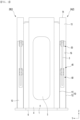
FIG. 2 is a front view illustrating an example of a cover according to the present embodiment, -
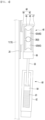
FIG. 3 is a side view illustrating the inside of a cable management according to the present embodiment, -
FIG. 4 is a cross-sectional view illustrating a moving roller and a damper according to the present embodiment, -
FIG. 5 is a perspective view illustrating another example of a charger according to the present embodiment, -
FIG. 6 is a front view illustrating another example of a charger according to the present embodiment, -
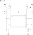
FIG. 7 is a plan view illustrating another example of a charger according to the present embodiment, -
FIG. 8 is a side view illustrating the other example of a charger according to the present embodiment. -
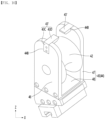
FIG. 9 is a perspective view illustrating another example of a moving pulley according to the present embodiment, -
FIG. 10 is a perspective view illustrating another example of a moving pulley according to the present embodiment. - Hereinafter, specific embodiments of the present invention will be described in detail with reference to the drawings.
-
FIG. 1 is a perspective view illustrating an example of a charger according to the present embodiment,FIG. 2 is a front view illustrating an example of a cover according to the present embodiment,FIG. 3 is a side view illustrating the inside of a cable management according to the present embodiment, andFIG. 4 is a cross-sectional view illustrating a moving roller and a damper according to the present embodiment. - The charger may comprise a
charger body 1 and acable management 2. - A
charging cable 3 may be connected to thecharger body 1. A plurality ofcharging cables 3 may be connected to thecharger body 1, and the plurality ofcharging cables 3 may be used independently. - The
charger body 1 may comprise acharger body 4 that forms an exterior and has an inner space formed therein, and a power module accommodated in the inner space. - One end of the
charging cable 3 may be connected to the power module, and a connector (charging gun or plug) connected to a vehicle such as an electric vehicle may be disposed at the other end of thecharging cable 1. - An outlet through which the
charging cable 3 passes may be formed on the side surface or rear surface of thecharger body 1. A plurality of outlets may be formed. The plurality of outlets may comprise a left outlet formed on the left surface of thecharger body 1, and a right outlet formed on the right surface of thecharger body 1. - A
display 5 that may display charging information may be placed on the front surface of thecharger body 1. - A
base 6 may be disposed on the lower portion of thecharger body 1. - The cross-sectional area of the
base 6 may be larger than the cross-sectional area of thecharger body 1. - The
cable management 2 may be disposed on the outside of thecharger body 1. - The
cable management 2 may be disposed on other than the front surface of thecharger body 1, and may be disposed on the rear surface or side surface of thecharger body 1. - One example of the
cable management 2 may be disposed away from the rear surface or side surface of thecharger body 1. The other example of thecable management 2 may be disposed in close contact with the rear surface or side surface of thecharger body 1. - An
outlet 16 through which acharging cable 3 passes may be formed in thecable management 2. If thecable management 2 is disposed next to thecharger body 1 and theoutlet 16 is formed at the front surface of thecable management 2, the overall length of thecharging cable 3 may be minimized, and hereinafter, thecable management 2 is described as being disposed next to thecharger body 1. - The
cable management 2 may be disposed on the left and right sides of thecharger body 1, respectively. - The charger may comprise a
left cable management 2A disposed on the left side of thecharger body 1 and aright cable management 2B disposed on the right side of thecharger body 1. - The charging cable extended to the left from the
charger body 1 may be managed by theleft cable management 2A. The charging cable extended to the right from thecharger body 1 may be managed by theright cable management 2B. - The
left cable management 2A and theright cable management 2B may have a structure that is symmetrical from left to right, and the common configuration of theleft cable management 2A and theright cable management 2B will be described below ascable management 2. - The
cable management 2 may comprise acover 10 having a space S formed in the cover; afirst pulley guide 20 and asecond pulley guide 30 disposed in thecover 10; a first movingpulley 40 guided by thefirst pulley guide 20 and moved by the chargingcable 3; and a second movingpulley 50 guided by thesecond pulley guide 30 and moved by the chargingcable 3. - The
cover 10 may be disposed next to thecharger body 1. Thecover 10 may have an overall rectangular solid shape. Thecover 10 may be formed such that the length in the up and down direction Z is longer than the length in the front and rear direction X. Thecover 10 may be formed so that the length (thickness) in the left and right direction Y is shorter than the length in the front and rear direction X. - As shown in
Fig. 1 , thecover 10 may comprise aninner plate 11 facing the side surface of thecharger body 1, anouter plate 12 spaced apart from theinner plate 11 in the left and right direction Y, afront plate 13 connecting the front end of theinner plate 11 and the front end of theouter plate 11, and anupper plate 14 connecting the upper end of theinner plate 11 and the upper end of theouter plate 11. - The
cover 10 may further comprise arear plate 15 connecting the rear end of theinner plate 11 and the rear end of theouter plate 11. Thecover 10 may further comprise a lower plate (not shown) connecting the lower end of theinner plate 11 and the lower end of theouter plate 11. - The
cover 10 may be disposed on the upper surface of thebase 6 disposed at the lower portion of thecharger body 1. - The
cover 10 may be disposed on thebase 6 so as to be spaced apart from the side surface of thecharger body 1. - The
inner plate 11 of thecover 10 may be spaced apart from the side surface of thecharger body 1, and a gap may be formed between thecover 10 and thecharger body 1. - The
cable management 2 may be a tower management parallel to thecharger body 1. - When servicing the
cable management 2, the worker may separate thecable management 2 from thebase 5, and the service of thecable management 2 may be easy. - The
cover 10 may be formed with anoutlet 16 through which the chargingcable 3 is drawn out of thecover 10. - The
outlet 16 may be formed on thefront plate 13 of thecover 10. - The
outlet 16 may be formed in front of the movement path of the second movingpulley 50. - The
outlet 16 may be formed to be open in thefront plate 13 of thecover 10 in the front and rear direction X. Theoutlet 16 may be formed to be long in the up and down direction Z on thefront plate 13 of thecover 10. - The
first pulley guide 20 and thesecond pulley guide 30 may have the same structure. - The
first pulley guide 20 may be spaced apart from thesecond pulley guide 30 in the front and rear direction X. - The
first pulley guide 20 may be disposed to be long in the up and down direction Z on thecover 10. - The
first pulley guide 20 may be disposed on theinner plate 11 facing the side surface of thecharger body 1 among theinner plate 11 and theouter plate 12 of thecover 10. - The
second pulley guide 30 may be disposed lengthwise in the up and down direction Z on thecover 10. - The
first pulley guide 20 may be disposed on theinner plate 11 facing the side surface of thecharger body 1 among theinner plate 11 and theouter plate 12 of thecover 10. - At least one of the first moving
pulley 40 and the second movingpulley 50 may comprise aroller 42 and abracket 44, as shown inFIG. 4 . - The first moving
pulley 40 and the second movingpulley 50 may have the same structure. Each of the first movingpulley 40 and the second movingpulley 50 may comprise aroller 42 and abracket 44. - A plurality of
rollers 42 may be provided on thebracket 44. The plurality ofrollers 42 may be spaced apart from each other. - The
roller 42 may comprise anupper roller 42A and alower roller 42B spaced apart from theupper roller 42A in the up and down direction Z. - A gap may be formed between the
upper roller 42A and thelower roller 42B to accommodate a portion of the chargingcable 3. - The charging
cable 3 may pass between theupper roller 42A and thelower roller 42B. A portion of the chargingcable 3 may be located in the gap. - The
bracket 44 may comprise aroller supporter 45 that rotatably supports theroller 42. - The
roller supporter 45 may have a three-dimensional shape. Theroller supporter 45 may comprise a pair ofside bodies roller 42, and a connectingbody 48 that connects the pair ofside bodies - The
bracket 44 may further comprise a slidingbody 49 that is guided up and down by thefirst pulley guide 20 or thesecond pulley guide 30. - The sliding
body 49 may be fastened to one of the pair ofside bodies - The sliding
body 49 of the first movingroller 40 may be guided up and down by thefirst roller guide 20. - The sliding
body 49 of the second movingpuller 50 may be guided up and down by thesecond roller guide 30. - One of the first moving
roller 40 and the second movingpuller 50 may be a front moving roller closer to thefront plate 13 of thecover 10, and the other of the first movingroller 40 and the second movingpuller 50 may be a rear moving roller closer to therear plate 15 of thecover 10. - The charging
cable 3 may comprise aninner cable 3A accommodated inside thecover 10, and anouter cable 3B extended from theinner cable 3A and positioned outside theoutlet 16. - The charging
cable 3 may comprise afirst bending cable 3C bent into a U shape by the first movingpulley 40, and asecond bending cable 3D extended from the firstinner cable 3C and bent into a ∩ shape by the weight of the second movingpulley 50 and theouter cable 3B. - The
inner cable 3A may comprise all of thefirst bending cable 3C and a portion of thesecond bending cable 3D. - The
outer cable 3B may comprise a portion of thesecond bending cable 3D positioned outside theoutlet 16. - The
bracket 44 of the first movingpulley 40 may be connected to a first wire mechanism having a wire that may be restored to a restoration position (initial position) of the first movingpulley 40. - The first wire mechanism may comprise a pulley that guides a wire disposed on the upper side of the first moving
pulley 40. The first wire mechanism may comprise a retractor or a spring balancer that pulls the wire. - The
bracket 44 of the second movingpulley 50 may be connected to a second wire mechanism having a wire that may be restored to a restoration position (initial position) of the second movingpulley 50. - The second wire mechanism may comprise a pulley that is disposed on the upper side of the second moving
pulley 50 and guides the wire. The second wire mechanism may comprise a retractor or a spring balancer that pulls the wire. - The charger may comprise a
damper 60. - The
damper 60 may be installed on either the first movingpulley 40 or the second movingpulley 50. - The
damper 60 may be installed on the movingpulley 40 that is farther from theexit 16 among the first movingpulley 40 and the second movingpulley 50. Thedamper 60 may be disposed on the rear moving roller. - An example of the
damper 60 may be a spring damper having aspring 61 built in, as shown inFIG. 4 . Thedamper 60 may comprise acylinder 62 in which a space in which thespring 61 is built in is formed, and arod 63 that is disposed to be lifted and lowered in thecylinder 62 and supported by thespring 61. - An example of the
damper 60 may comprise acylinder 62 mounted on acover 10. - An example of a
damper 60 is that oneend 64 of arod 63 may be accommodated in acylinder 62 and connected to aspring 61. An example of adamper 60 is that theother end 66 of therod 62 may be positioned outside thecylinder 62 and connected to abracket 44. - An example of a
damper 60 is that therod 62 may be connected to abracket 44 of a rear moving roller, thedamper 60 may limit a sudden rise of thebracket 44, and thespring 61 may absorb a shock that may occur when thebracket 44 is suddenly lowered. - Another example of a
damper 60 may comprise acylinder 62 mounted on abracket 44 of a rear moving roller. - The other example of the
damper 60 is that oneend 64 of therod 63 may be accommodated in thecylinder 62 and connected to thespring 61. The other example of thedamper 60 is that theother end 66 of therod 62 may be located outside thecylinder 62 and may be in contact with or separated from thecover 10. - The other example of the
damper 60 is that thedamper 60 may limit the rapid lowering of thebracket 44, and thespring 61 of thedamper 60 may absorb the shock that may occur when thebracket 44 is rapidly lowered. -
FIG. 5 is a perspective view illustrating another example of a charger according to the present embodiment,FIG. 6 is a front view illustrating another example of a charger according to the present embodiment, andFIG. 7 is a plan view illustrating another example of a charger according to the present embodiment. - The cover 10' may be fastened to the
bracket 7 installed on thecharger body 1. - The
bracket 7 may be disposed on the side surface of thecharger body 1. - The cover 10' may be fastened to the
bracket 7, and thecable management 2 may be integrated with thecharger body 1. The load of thecable management 2 may be applied to thecharger body 1. - The cover 10' may further comprise, like the
cover 10 of the charger, aninner plate 11, anouter plate 12 spaced apart from theinner plate 11 in the left and right direction Y, afront plate 13 connecting the front end of theinner plate 11 and the front end of theouter plate 11, aupper plate 14 connecting the upper end of theinner plate 11 and the upper end of theouter plate 11, and arear plate 15 connecting the rear end of theinner plate 11 and the rear end of theouter plate 11. - The
inner plate 11 of the cover 10' may be mounted on the 16 7 with a fastening member such as a screw or a hanging member such as a hook. - When servicing the
cable management 2, the worker may detach thecable management 2 from thebracket 7, and the service of thecable management 2 may be easy. -
FIG. 8 is a side view illustrating the other example of a charger according to the present embodiment. - The other example of a charger may comprise a
connector 70. - The
connector 70 may be connected to each of the first movingpulley 40 and the second movingpulley 50. - The
connector 70 may cause the first movingpulley 40 and the second movingpulley 50 to move in opposite directions. - The
connector 70 may cause the first movingpulley 40 and the second movingpulley 50 to move in opposite directions. Theconnector 70 may cause the other of the first movingpulley 40 and the second movingpulley 50 to move down when one of the first movingpulley 40 and the second movingpulley 50 moves up. Theconnector 70 may cause the other of the first movingpulley 40 and the second movingpulley 50 to move up when one of the first movingpulley 40 and the second movingpulley 50 moves down. - A length of the
connector 70 may be shortened in length when the first movingpulley 40 and the second movingpulley 50 come close, and may be lengthened when the first movingpulley 40 and the second movingpulley 50 move farther apart. - The
connector 70 may push each of the first movingpulley 40 and the second movingpulley 50 so that each of the first movingpulley 40 and the second movingpulley 50 is positioned in a restored position. - The
connector 70 may push each of the first movingpulley 40 and the second movingpulley 50 in opposite directions, and may help restore the first movingpulley 40 and the second movingpulley 50, and may reliably restore the chargingcable 3. - For example, the restoration position of the first moving
pulley 40 may be the lower limit position of the first movingpulley 40, and the restoration position of the second moving pulley 500 may be the upper limit position of the second movingpulley 50, and if no external force (pulling force) is applied to the chargingcable 2 from the outside, theconnector 70 may push the first movingpulley 40 to the restoration position (lower limit position) and push the second movingpulley 50 to the restoration position (upper limit position). - An example of the
connector 70 may comprise acylinder 72 disposed on thecover 10; afirst rod 74 disposed to advance and retreat in the longitudinal direction of thecylinder 72 and connected to the first movingpulley 40, and asecond rod 76 disposed to advance and retreat in the longitudinal direction of thecylinder 72 and connected to the second movingpulley 50. - The
cylinder 72 may be rotatably disposed on thecover 10. - The inside of the
cylinder 72 may be filled with gas. - The
first rod 74 may be rotatably connected to thebracket 44 of the first movingpulley 40. - The
second rod 76 may be rotatably connected to thebracket 44 of the second movingpulley 50. - When the first moving
pulley 40 and the second movingpulley 50 approach each other, thefirst rod 74 and thesecond rod 76 may be retracted toward thecylinder 72, and when the first movingpulley 40 and the second movingpulley 50 move away, thefirst rod 74 and thesecond rod 76 may be advanced toward the outside of thecylinder 72. - If the charging
cable 3 is pulled by an external force, the first movingroller 40 may be raised, the second movingroller 50 may be lowered, thefirst rod 74 may be inserted into thecylinder 72 by the first movingroller 40 and may compress gas and thesecond rod 76 may be inserted into thecylinder 72 by the second movingroller 50 and may compress gas. - An example of the
connector 70 may push thefirst rod 74 and thesecond rod 76 outwardly by the restoring force of the gas. If the external force (pulling force) applied to the chargingcable 3 is removed, thefirst rod 74 may reliably push the first movingpulley 40 to the restoring position (lower limit position), and thesecond rod 76 may reliably push the second movingpulley 50 to the restoring position (upper limit position). - Another example of the
connector 70 may comprise a spring. A first connecting portion connected to the first movingpulley 40 may be formed on one side of the spring and a second connecting portion connected to the second movingpulley 50 may be formed on other side of the spring. - If an external force (pulling force) is applied to the charging
cable 3, and the first movingroller 40 and the second movingroller 50 come close, the spring may be compressed and may elastically support the first movingroller 40 and the second movingroller 50. - If the external force pulling (force applied) to the charging
cable 3 is removed, the spring may reliably push the first movingpulley 40 to the restoration position (lower limit position), and thesecond rod 76 may reliably push the second movingpulley 50 to the restoration position (upper limit position). - The other example of a connector may comprise a shaft.
- A first connecting portion connected to the first moving
pulley 40 may be formed on one side of the shaft and a second connecting portion connected to the second movingpulley 40 may be formed other side to the shaft.
he charger may further comprise agas spring 80. - The
gas spring 80 may be connected to a moving pulley closer to theoutlet 16 among the first movingpulley 40 and the second movingpulley 50. - The
gas spring 80 may be connected to a front pulley located in the front among the first movingpulley 40 and the second movingpulley 50, and may be connected to the second movingpulley 50. - The
gas spring 80 may be connected to abracket 44 of the second movingpulley 50. - The
gas spring 80 may limit rapid elevation of the second movingpulley 50 at the lower of the second movingpulley 50 and may assist in the restoration of the second movingpulley 80. - The
gas spring 80 may comprise arod 82 connected to thebracket 44 of the second movingpulley 50 and acylinder 84 through which therod 82 is raised and lowered, and gas may be accommodated inside thecylinder 84. - The
cylinder 84 may be disposed in thecover 10. - The
rod 82 may be raised and lowered in the up-and-down direction Z. - The
gas spring 80 may limit a rapid lowering of the front moving pulley. -
FIG. 9 is a perspective view illustrating another example of a moving pulley according to the present embodiment. - At least one example of the first moving
pulley 40 and the second movingpulley 50 may comprise aroller 42, astopper 43, and abracket 44. The first movingpulley 40 and the second movingpulley 50 may have the same structure, and hereinafter are referred to as moving pulleys. - The moving pulley may be raised or lowered by the charging
cable 3. - The
roller 42 may be rotatably disposed on thebracket 44. - A
single roller 42 may be rotatably disposed on thebracket 44. - The
stopper 43 may be attached to thebracket 44 so as to be spaced apart from theroller 42. - The charging
cable 3 may pass through the gap between thestopper 43 and theroller 42. - The
stopper 43 may comprise a sub-body 43A that is fastened to thebracket 44 and a sub-roller 43B that is rotatably supported by the sub-body 44A. - The sub-body 43A may be inserted into a
stopper mounting groove 44A formed in thebracket 44 and may be accommodated in thestopper mounting groove 44A. - The sub-body 43A may be fastened to the
bracket 44 by a fastening member such as a screw. - The sub-roller 43B may be spaced apart from the
roller 42 in the up and down direction Z. - The diameter of the sub-roller 43B may be smaller than the diameter of the
roller 42. - With the
stopper 43 separated from thebracket 44, the chargingcable 3 may be placed on theroller 42 of the moving pulley, and with the chargingcable 3 placed on theroller 42, thestopper 43 may be fastened to thebracket 44. -
FIG. 10 is a perspective view illustrating another example of a moving pulley according to the present embodiment. - Another example of a moving pulley may comprise a
roller 42, a stopper 43', and abracket 44. - The
roller 42 and thebracket 44 may be the same as or similar to the moving pulley illustrated inFIG. 9 , and to avoid duplicate description, the same reference numerals are used, and detailed descriptions thereof are omitted. - The stopper 43' may be a stopper pin mounted on the
bracket 44. - The stopper 43' may be mounted by being fitted onto the
bracket 44. The stopper 43' may be mounted on thebracket 44 using a fastening member such as a screw. - A pair of stoppers 43' may be installed on the
bracket 44. The pair of stoppers 43' may be spaced apart from each other. The pair of stoppers 43' may be spaced apart in the horizontal direction. The distance between the pair of stoppers 43' may be smaller than the diameter of the chargingcable 3. - The stopper 43' may comprise a
fastening body 43C fastened to thebracket 44 and a protrudingbody 43D protruding from thefastening body 43C and spaced apart from theroller 42. - The
fastening body 43C may be inserted into astopper mounting groove 44B formed in thebracket 44 and may be accommodated in thestopper mounting groove 44B. - The
fastening body 43C may be fastened to thebracket 44 by a fastening member such as a screw. - The protruding
body 43D may be bent orthogonally to thefastening body 43C. - The protruding
body 43D may be spaced apart from theroller 42 in the up and down direction Z. - The above description is merely an illustrative explanation of the technical idea of the present disclosure, and various modifications and variations will be possible to those skilled in the art without departing from the essential characteristics of the present disclosure.
- Accordingly, the embodiments disclosed in the present disclosure are not intended to limit the technical idea of the present disclosure, but rather to explain it, and the scope of the technical idea of the present disclosure is not limited by these embodiments.
- The scope of protection of the present disclosure should be interpreted in accordance with the claims below, and all technical ideas within the equivalent scope should be construed as being comprised in the scope of rights of the present disclosure.
Claims (16)
- A charger comprising;a cover having a space formed in the cover;a first pulley guide and a second pulley guide disposed in the cover;a first moving pulley guided by the first pulley guide and moved by a charging cable;a second moving pulley guided by the second pulley guide and moved by the charging cable; anda damper installed on one of the first moving pulley and the second moving pulley.
- The charger of claim 1,
wherein the cover is disposed next to a charger body. - The charger of claim 1,
wherein the cover is a disposed on a upper surface of a base disposed at the lower portion of a charger body. - The charger of claim 1,
wherein the cover is fastened to a bracket installed on a charger body. - The charger of claim 1,wherein an outlet through which the charging cable is drawn out of the cover is formed on the cover,and the damper is installed on a moving pulley farther from the outlet among the first moving pulley and the second moving pulley.
- The charger of claim 1, further comprising;
a connector connected to each of the first moving pulley and the second moving pulley and causing the first moving pulley and the second moving pulley to move in opposite directions. - The charger of claim 6,wherein a length of the connector is reduced when the first moving pulley and the second moving pulley approach each other,and the length of the connector is increased when the first moving pulley and the second moving pulley move away from each other.
- The charger of claim 6,
wherein the connector comprisesa cylinder disposed in the cover;a first rod disposed to advance and retreat in a longitudinal direction of the cylinder and connected to the first moving pulley; anda second rod disposed to advance and retreat in the longitudinal direction of the cylinder and connected to the second moving pulley. - The charger of claim 8,
wherein the cylinder is rotatably disposed on the cover. - The charger of claim 8,
wherein the cylinder is a gas cylinder having gas filled in the gas cylinder. - The charger of claim 6,
wherein the connector comprisesa spring having a first connecting portion formed on one side of the connector and connected to the first moving pulley anda second connecting portion formed on the other side of the connector and connected to the second moving pulley. - The charger of claim 1, further comprising;wherein an outlet through which the charging cable is drawn out of the cover is formed on the cover,the charger further comprises
a gas spring connected to a moving pulley closer to the exit among the first moving pulley and the second moving pulley. - The charger of claim 1,
wherein at least one of the first moving pulley and the second moving pulley comprises:a roller;a bracket on which the roller is rotatably installed; anda stopper attached to the bracket and spaced apart from the roller,wherein the charging cable passes through a gap between the stopper and the roller. - The charger of claim 13,
wherein the stopper comprises:a sub-body attached to the bracket; anda sub-roller rotatably supported on the sub-body. - The charger of claim 14,
wherein a diameter of the sub-roller is smaller than a diameter of the roller. - The charger of claim 13,
wherein the stopper comprises:a fastening body attached to the bracket; anda protruding body protruding from the fastening body and spaced apart from the roller.
Applications Claiming Priority (2)
| Application Number | Priority Date | Filing Date | Title |
|---|---|---|---|
| KR20230039937 | 2023-03-27 | ||
| PCT/KR2023/019924 WO2024204950A1 (en) | 2023-03-27 | 2023-12-05 | Charger |
Publications (1)
| Publication Number | Publication Date |
|---|---|
| EP4578715A1 true EP4578715A1 (en) | 2025-07-02 |
Family
ID=92906973
Family Applications (1)
| Application Number | Title | Priority Date | Filing Date |
|---|---|---|---|
| EP23931058.4A Withdrawn EP4578715A1 (en) | 2023-03-27 | 2023-12-05 | Charger |
Country Status (4)
| Country | Link |
|---|---|
| US (1) | US20260100566A1 (en) |
| EP (1) | EP4578715A1 (en) |
| KR (5) | KR102797612B1 (en) |
| WO (1) | WO2024204950A1 (en) |
Family Cites Families (16)
| Publication number | Priority date | Publication date | Assignee | Title |
|---|---|---|---|---|
| EP2238667A2 (en) | 2008-01-14 | 2010-10-13 | Aerovironment | Sliding conductor transmission cable |
| JP5442587B2 (en) * | 2010-12-03 | 2014-03-12 | 中国電力株式会社 | Charger |
| WO2017127428A1 (en) * | 2016-01-18 | 2017-07-27 | Conductix, Inc | Retractable cable or hose system |
| JP6720011B2 (en) * | 2016-07-29 | 2020-07-08 | トヨタホーム株式会社 | Charger |
| KR102002779B1 (en) * | 2017-03-17 | 2019-07-23 | 김기섭 | Charging cable length control device for eletric vehicles |
| KR102142206B1 (en) * | 2019-01-15 | 2020-08-06 | 주식회사 유경시스템 | Seismic retrofit of existing structue using spring damper and multipoint prestressed cable |
| KR102207226B1 (en) * | 2019-03-15 | 2021-01-25 | 대영채비(주) | An electric vehicle charging device equipped with an adjusting means in a charging charge |
| KR20210004480A (en) * | 2019-07-04 | 2021-01-13 | (주)클린일렉스 | Rapidly charging cable arrangement apparatus for electric vehicle |
| CN210337634U (en) * | 2019-07-19 | 2020-04-17 | 青岛网信信息科技有限公司 | Charging pile capable of automatically winding up |
| KR102101479B1 (en) | 2019-10-04 | 2020-05-26 | (주)클린일렉스 | Rapid charging apparatus for electric vehicle having automatic cable arrangement |
| KR102335829B1 (en) * | 2020-03-11 | 2021-12-06 | (주)클린일렉스 | Rapid charging apparatus for electric vehicle having automatic cable arrangement |
| KR102358252B1 (en) * | 2020-02-28 | 2022-02-07 | (주)멥카 | Charging cable controlling apparatus of electric car charger |
| KR20220056530A (en) * | 2020-10-28 | 2022-05-06 | 대영채비(주) | Dual-Type Moving Electric Vehicle Charger |
| KR20220068612A (en) * | 2020-11-19 | 2022-05-26 | 주식회사 엔터정밀 | Cable management device |
| CN112744111B (en) * | 2021-03-04 | 2024-02-09 | 青岛跃东新能源汽车销售租赁有限公司 | New energy automobile public fills electric pile |
| CN215402374U (en) * | 2021-05-26 | 2022-01-04 | 上海Abb联桩新能源技术有限公司 | Suspension type rifle line receiving mechanism and rack of using thereof |
-
2023
- 2023-08-08 KR KR1020230103551A patent/KR102797612B1/en active Active
- 2023-08-08 KR KR1020230103550A patent/KR102797605B1/en active Active
- 2023-08-08 KR KR1020230103552A patent/KR20240145364A/en not_active Withdrawn
- 2023-08-08 KR KR1020230103549A patent/KR20240145361A/en active Pending
- 2023-12-05 US US19/112,763 patent/US20260100566A1/en active Pending
- 2023-12-05 KR KR1020247024471A patent/KR102830449B1/en active Active
- 2023-12-05 WO PCT/KR2023/019924 patent/WO2024204950A1/en not_active Ceased
- 2023-12-05 EP EP23931058.4A patent/EP4578715A1/en not_active Withdrawn
Also Published As
| Publication number | Publication date |
|---|---|
| KR20240145363A (en) | 2024-10-07 |
| KR20240145361A (en) | 2024-10-07 |
| KR20240145364A (en) | 2024-10-07 |
| KR20240145362A (en) | 2024-10-07 |
| KR102797605B1 (en) | 2025-04-23 |
| US20260100566A1 (en) | 2026-04-09 |
| KR102797612B1 (en) | 2025-04-23 |
| KR20240146660A (en) | 2024-10-08 |
| WO2024204950A1 (en) | 2024-10-03 |
| KR102830449B1 (en) | 2025-07-08 |
Similar Documents
| Publication | Publication Date | Title |
|---|---|---|
| EP4439891A1 (en) | Charger | |
| KR102358252B1 (en) | Charging cable controlling apparatus of electric car charger | |
| EP4439889A1 (en) | Charger | |
| EP4439890A1 (en) | Charger | |
| CN112440787A (en) | Charging station for an electrically operated vehicle | |
| KR20240038428A (en) | Apparatus For Holding Plate Reel Of Plate Slitting Machine For Secondary Battery | |
| EP4578715A1 (en) | Charger | |
| CA3227279A1 (en) | Bollard cord retractor | |
| CN212124902U (en) | Electric automobile fills electric pile convenient to accomodate electric wire | |
| EP4592132A1 (en) | Charger | |
| EP4439888A1 (en) | Charger | |
| CN105826796B (en) | Installation aiding device | |
| KR20240173408A (en) | An electric vehicle charging device that can automatically control the retractable length of the charging cable | |
| EP4596305A1 (en) | Charger | |
| CN213938623U (en) | Protective device for communication equipment | |
| US20250379440A1 (en) | Charger | |
| CN224118522U (en) | Communication cable winding and unwinding device for railway communication engineering | |
| CN218241931U (en) | Coil needle blanking mechanism capable of improving overall strength | |
| CN220544101U (en) | Shockproof and explosion-proof lithium battery pack for unmanned aerial vehicle | |
| CN215828020U (en) | Cable pay-off rack | |
| CN222809207U (en) | Arm support structure and aerial work platform | |
| CN120955482B (en) | A portable mobile device for a mobile switch box | |
| US20250236189A1 (en) | Supply system for an electrical line, in particular for a charging cable for an electric vehicle | |
| KR20260007893A (en) | Charing system | |
| CN213989458U (en) | A data transmission harness for unmanned aerial vehicles |
Legal Events
| Date | Code | Title | Description |
|---|---|---|---|
| STAA | Information on the status of an ep patent application or granted ep patent |
Free format text: STATUS: THE INTERNATIONAL PUBLICATION HAS BEEN MADE |
|
| PUAI | Public reference made under article 153(3) epc to a published international application that has entered the european phase |
Free format text: ORIGINAL CODE: 0009012 |
|
| STAA | Information on the status of an ep patent application or granted ep patent |
Free format text: STATUS: REQUEST FOR EXAMINATION WAS MADE |
|
| 17P | Request for examination filed |
Effective date: 20250323 |
|
| AK | Designated contracting states |
Kind code of ref document: A1 Designated state(s): AL AT BE BG CH CY CZ DE DK EE ES FI FR GB GR HR HU IE IS IT LI LT LU LV MC ME MK MT NL NO PL PT RO RS SE SI SK SM TR |
|
| STAA | Information on the status of an ep patent application or granted ep patent |
Free format text: STATUS: THE APPLICATION HAS BEEN WITHDRAWN |
|
| 18W | Application withdrawn |
Effective date: 20250804 |