EP4578616A1 - Fibrous filler stirring/supplying device, supply method, manufacturing method, and manufacturing method for thermoplastic resin composition - Google Patents
Fibrous filler stirring/supplying device, supply method, manufacturing method, and manufacturing method for thermoplastic resin composition Download PDFInfo
- Publication number
- EP4578616A1 EP4578616A1 EP23856898.4A EP23856898A EP4578616A1 EP 4578616 A1 EP4578616 A1 EP 4578616A1 EP 23856898 A EP23856898 A EP 23856898A EP 4578616 A1 EP4578616 A1 EP 4578616A1
- Authority
- EP
- European Patent Office
- Prior art keywords
- fibrous filler
- stirring
- stirring blade
- connecting tank
- shaft
- Prior art date
- Legal status (The legal status is an assumption and is not a legal conclusion. Google has not performed a legal analysis and makes no representation as to the accuracy of the status listed.)
- Pending
Links
Images



Classifications
-
- B—PERFORMING OPERATIONS; TRANSPORTING
- B29—WORKING OF PLASTICS; WORKING OF SUBSTANCES IN A PLASTIC STATE IN GENERAL
- B29B—PREPARATION OR PRETREATMENT OF THE MATERIAL TO BE SHAPED; MAKING GRANULES OR PREFORMS; RECOVERY OF PLASTICS OR OTHER CONSTITUENTS OF WASTE MATERIAL CONTAINING PLASTICS
- B29B7/00—Mixing; Kneading
- B29B7/80—Component parts, details or accessories; Auxiliary operations
- B29B7/88—Adding charges, i.e. additives
- B29B7/90—Fillers or reinforcements, e.g. fibres
-
- B—PERFORMING OPERATIONS; TRANSPORTING
- B01—PHYSICAL OR CHEMICAL PROCESSES OR APPARATUS IN GENERAL
- B01F—MIXING, e.g. DISSOLVING, EMULSIFYING OR DISPERSING
- B01F23/00—Mixing according to the phases to be mixed, e.g. dispersing or emulsifying
- B01F23/50—Mixing liquids with solids
- B01F23/57—Mixing high-viscosity liquids with solids
-
- B—PERFORMING OPERATIONS; TRANSPORTING
- B01—PHYSICAL OR CHEMICAL PROCESSES OR APPARATUS IN GENERAL
- B01F—MIXING, e.g. DISSOLVING, EMULSIFYING OR DISPERSING
- B01F27/00—Mixers with rotary stirring devices in fixed receptacles; Kneaders
- B01F27/05—Stirrers
- B01F27/11—Stirrers characterised by the configuration of the stirrers
- B01F27/112—Stirrers characterised by the configuration of the stirrers with arms, paddles, vanes or blades
-
- B—PERFORMING OPERATIONS; TRANSPORTING
- B01—PHYSICAL OR CHEMICAL PROCESSES OR APPARATUS IN GENERAL
- B01F—MIXING, e.g. DISSOLVING, EMULSIFYING OR DISPERSING
- B01F27/00—Mixers with rotary stirring devices in fixed receptacles; Kneaders
- B01F27/05—Stirrers
- B01F27/11—Stirrers characterised by the configuration of the stirrers
- B01F27/112—Stirrers characterised by the configuration of the stirrers with arms, paddles, vanes or blades
- B01F27/1123—Stirrers characterised by the configuration of the stirrers with arms, paddles, vanes or blades sickle-shaped, i.e. curved in at least one direction
-
- B—PERFORMING OPERATIONS; TRANSPORTING
- B01—PHYSICAL OR CHEMICAL PROCESSES OR APPARATUS IN GENERAL
- B01F—MIXING, e.g. DISSOLVING, EMULSIFYING OR DISPERSING
- B01F27/00—Mixers with rotary stirring devices in fixed receptacles; Kneaders
- B01F27/60—Mixers with rotary stirring devices in fixed receptacles; Kneaders with stirrers rotating about a horizontal or inclined axis
- B01F27/61—Mixers with rotary stirring devices in fixed receptacles; Kneaders with stirrers rotating about a horizontal or inclined axis about an inclined axis
-
- B—PERFORMING OPERATIONS; TRANSPORTING
- B01—PHYSICAL OR CHEMICAL PROCESSES OR APPARATUS IN GENERAL
- B01F—MIXING, e.g. DISSOLVING, EMULSIFYING OR DISPERSING
- B01F27/00—Mixers with rotary stirring devices in fixed receptacles; Kneaders
- B01F27/60—Mixers with rotary stirring devices in fixed receptacles; Kneaders with stirrers rotating about a horizontal or inclined axis
- B01F27/70—Mixers with rotary stirring devices in fixed receptacles; Kneaders with stirrers rotating about a horizontal or inclined axis with paddles, blades or arms
-
- B—PERFORMING OPERATIONS; TRANSPORTING
- B01—PHYSICAL OR CHEMICAL PROCESSES OR APPARATUS IN GENERAL
- B01F—MIXING, e.g. DISSOLVING, EMULSIFYING OR DISPERSING
- B01F35/00—Accessories for mixers; Auxiliary operations or auxiliary devices; Parts or details of general application
- B01F35/20—Measuring; Control or regulation
- B01F35/21—Measuring
- B01F35/213—Measuring of the properties of the mixtures, e.g. temperature, density or colour
-
- B—PERFORMING OPERATIONS; TRANSPORTING
- B01—PHYSICAL OR CHEMICAL PROCESSES OR APPARATUS IN GENERAL
- B01F—MIXING, e.g. DISSOLVING, EMULSIFYING OR DISPERSING
- B01F35/00—Accessories for mixers; Auxiliary operations or auxiliary devices; Parts or details of general application
- B01F35/71—Feed mechanisms
-
- B—PERFORMING OPERATIONS; TRANSPORTING
- B01—PHYSICAL OR CHEMICAL PROCESSES OR APPARATUS IN GENERAL
- B01F—MIXING, e.g. DISSOLVING, EMULSIFYING OR DISPERSING
- B01F35/00—Accessories for mixers; Auxiliary operations or auxiliary devices; Parts or details of general application
- B01F35/71—Feed mechanisms
- B01F35/717—Feed mechanisms characterised by the means for feeding the components to the mixer
- B01F35/7173—Feed mechanisms characterised by the means for feeding the components to the mixer using gravity, e.g. from a hopper
- B01F35/71731—Feed mechanisms characterised by the means for feeding the components to the mixer using gravity, e.g. from a hopper using a hopper
-
- B—PERFORMING OPERATIONS; TRANSPORTING
- B01—PHYSICAL OR CHEMICAL PROCESSES OR APPARATUS IN GENERAL
- B01F—MIXING, e.g. DISSOLVING, EMULSIFYING OR DISPERSING
- B01F35/00—Accessories for mixers; Auxiliary operations or auxiliary devices; Parts or details of general application
- B01F35/75—Discharge mechanisms
-
- B—PERFORMING OPERATIONS; TRANSPORTING
- B29—WORKING OF PLASTICS; WORKING OF SUBSTANCES IN A PLASTIC STATE IN GENERAL
- B29B—PREPARATION OR PRETREATMENT OF THE MATERIAL TO BE SHAPED; MAKING GRANULES OR PREFORMS; RECOVERY OF PLASTICS OR OTHER CONSTITUENTS OF WASTE MATERIAL CONTAINING PLASTICS
- B29B7/00—Mixing; Kneading
- B29B7/02—Mixing; Kneading non-continuous, with mechanical mixing or kneading devices, i.e. batch type
- B29B7/06—Mixing; Kneading non-continuous, with mechanical mixing or kneading devices, i.e. batch type with movable mixing or kneading devices
- B29B7/10—Mixing; Kneading non-continuous, with mechanical mixing or kneading devices, i.e. batch type with movable mixing or kneading devices rotary
- B29B7/12—Mixing; Kneading non-continuous, with mechanical mixing or kneading devices, i.e. batch type with movable mixing or kneading devices rotary with single shaft
- B29B7/16—Mixing; Kneading non-continuous, with mechanical mixing or kneading devices, i.e. batch type with movable mixing or kneading devices rotary with single shaft with paddles or arms
-
- B—PERFORMING OPERATIONS; TRANSPORTING
- B29—WORKING OF PLASTICS; WORKING OF SUBSTANCES IN A PLASTIC STATE IN GENERAL
- B29B—PREPARATION OR PRETREATMENT OF THE MATERIAL TO BE SHAPED; MAKING GRANULES OR PREFORMS; RECOVERY OF PLASTICS OR OTHER CONSTITUENTS OF WASTE MATERIAL CONTAINING PLASTICS
- B29B7/00—Mixing; Kneading
- B29B7/02—Mixing; Kneading non-continuous, with mechanical mixing or kneading devices, i.e. batch type
- B29B7/22—Component parts, details or accessories; Auxiliary operations
- B29B7/24—Component parts, details or accessories; Auxiliary operations for feeding
-
- B—PERFORMING OPERATIONS; TRANSPORTING
- B29—WORKING OF PLASTICS; WORKING OF SUBSTANCES IN A PLASTIC STATE IN GENERAL
- B29B—PREPARATION OR PRETREATMENT OF THE MATERIAL TO BE SHAPED; MAKING GRANULES OR PREFORMS; RECOVERY OF PLASTICS OR OTHER CONSTITUENTS OF WASTE MATERIAL CONTAINING PLASTICS
- B29B7/00—Mixing; Kneading
- B29B7/02—Mixing; Kneading non-continuous, with mechanical mixing or kneading devices, i.e. batch type
- B29B7/22—Component parts, details or accessories; Auxiliary operations
- B29B7/26—Component parts, details or accessories; Auxiliary operations for discharging, e.g. doors
-
- B—PERFORMING OPERATIONS; TRANSPORTING
- B29—WORKING OF PLASTICS; WORKING OF SUBSTANCES IN A PLASTIC STATE IN GENERAL
- B29B—PREPARATION OR PRETREATMENT OF THE MATERIAL TO BE SHAPED; MAKING GRANULES OR PREFORMS; RECOVERY OF PLASTICS OR OTHER CONSTITUENTS OF WASTE MATERIAL CONTAINING PLASTICS
- B29B7/00—Mixing; Kneading
- B29B7/02—Mixing; Kneading non-continuous, with mechanical mixing or kneading devices, i.e. batch type
- B29B7/22—Component parts, details or accessories; Auxiliary operations
- B29B7/28—Component parts, details or accessories; Auxiliary operations for measuring, controlling or regulating, e.g. viscosity control
- B29B7/283—Component parts, details or accessories; Auxiliary operations for measuring, controlling or regulating, e.g. viscosity control measuring data of the driving system, e.g. torque, speed, power
-
- B—PERFORMING OPERATIONS; TRANSPORTING
- B29—WORKING OF PLASTICS; WORKING OF SUBSTANCES IN A PLASTIC STATE IN GENERAL
- B29B—PREPARATION OR PRETREATMENT OF THE MATERIAL TO BE SHAPED; MAKING GRANULES OR PREFORMS; RECOVERY OF PLASTICS OR OTHER CONSTITUENTS OF WASTE MATERIAL CONTAINING PLASTICS
- B29B7/00—Mixing; Kneading
- B29B7/30—Mixing; Kneading continuous, with mechanical mixing or kneading devices
- B29B7/34—Mixing; Kneading continuous, with mechanical mixing or kneading devices with movable mixing or kneading devices
- B29B7/38—Mixing; Kneading continuous, with mechanical mixing or kneading devices with movable mixing or kneading devices rotary
- B29B7/40—Mixing; Kneading continuous, with mechanical mixing or kneading devices with movable mixing or kneading devices rotary with single shaft
- B29B7/42—Mixing; Kneading continuous, with mechanical mixing or kneading devices with movable mixing or kneading devices rotary with single shaft with screw or helix
-
- B—PERFORMING OPERATIONS; TRANSPORTING
- B29—WORKING OF PLASTICS; WORKING OF SUBSTANCES IN A PLASTIC STATE IN GENERAL
- B29B—PREPARATION OR PRETREATMENT OF THE MATERIAL TO BE SHAPED; MAKING GRANULES OR PREFORMS; RECOVERY OF PLASTICS OR OTHER CONSTITUENTS OF WASTE MATERIAL CONTAINING PLASTICS
- B29B7/00—Mixing; Kneading
- B29B7/30—Mixing; Kneading continuous, with mechanical mixing or kneading devices
- B29B7/58—Component parts, details or accessories; Auxiliary operations
- B29B7/60—Component parts, details or accessories; Auxiliary operations for feeding, e.g. end guides for the incoming material
-
- B—PERFORMING OPERATIONS; TRANSPORTING
- B29—WORKING OF PLASTICS; WORKING OF SUBSTANCES IN A PLASTIC STATE IN GENERAL
- B29B—PREPARATION OR PRETREATMENT OF THE MATERIAL TO BE SHAPED; MAKING GRANULES OR PREFORMS; RECOVERY OF PLASTICS OR OTHER CONSTITUENTS OF WASTE MATERIAL CONTAINING PLASTICS
- B29B7/00—Mixing; Kneading
- B29B7/30—Mixing; Kneading continuous, with mechanical mixing or kneading devices
- B29B7/58—Component parts, details or accessories; Auxiliary operations
- B29B7/60—Component parts, details or accessories; Auxiliary operations for feeding, e.g. end guides for the incoming material
- B29B7/603—Component parts, details or accessories; Auxiliary operations for feeding, e.g. end guides for the incoming material in measured doses, e.g. proportioning of several materials
-
- B—PERFORMING OPERATIONS; TRANSPORTING
- B29—WORKING OF PLASTICS; WORKING OF SUBSTANCES IN A PLASTIC STATE IN GENERAL
- B29B—PREPARATION OR PRETREATMENT OF THE MATERIAL TO BE SHAPED; MAKING GRANULES OR PREFORMS; RECOVERY OF PLASTICS OR OTHER CONSTITUENTS OF WASTE MATERIAL CONTAINING PLASTICS
- B29B7/00—Mixing; Kneading
- B29B7/30—Mixing; Kneading continuous, with mechanical mixing or kneading devices
- B29B7/58—Component parts, details or accessories; Auxiliary operations
- B29B7/72—Measuring, controlling or regulating
-
- B—PERFORMING OPERATIONS; TRANSPORTING
- B29—WORKING OF PLASTICS; WORKING OF SUBSTANCES IN A PLASTIC STATE IN GENERAL
- B29B—PREPARATION OR PRETREATMENT OF THE MATERIAL TO BE SHAPED; MAKING GRANULES OR PREFORMS; RECOVERY OF PLASTICS OR OTHER CONSTITUENTS OF WASTE MATERIAL CONTAINING PLASTICS
- B29B9/00—Making granules
- B29B9/12—Making granules characterised by structure or composition
- B29B9/14—Making granules characterised by structure or composition fibre-reinforced
-
- B—PERFORMING OPERATIONS; TRANSPORTING
- B29—WORKING OF PLASTICS; WORKING OF SUBSTANCES IN A PLASTIC STATE IN GENERAL
- B29C—SHAPING OR JOINING OF PLASTICS; SHAPING OF MATERIAL IN A PLASTIC STATE, NOT OTHERWISE PROVIDED FOR; AFTER-TREATMENT OF THE SHAPED PRODUCTS, e.g. REPAIRING
- B29C48/00—Extrusion moulding, i.e. expressing the moulding material through a die or nozzle which imparts the desired form; Apparatus therefor
- B29C48/25—Component parts, details or accessories; Auxiliary operations
- B29C48/285—Feeding the extrusion material to the extruder
- B29C48/286—Raw material dosing
-
- B—PERFORMING OPERATIONS; TRANSPORTING
- B29—WORKING OF PLASTICS; WORKING OF SUBSTANCES IN A PLASTIC STATE IN GENERAL
- B29C—SHAPING OR JOINING OF PLASTICS; SHAPING OF MATERIAL IN A PLASTIC STATE, NOT OTHERWISE PROVIDED FOR; AFTER-TREATMENT OF THE SHAPED PRODUCTS, e.g. REPAIRING
- B29C48/00—Extrusion moulding, i.e. expressing the moulding material through a die or nozzle which imparts the desired form; Apparatus therefor
- B29C48/25—Component parts, details or accessories; Auxiliary operations
- B29C48/285—Feeding the extrusion material to the extruder
- B29C48/287—Raw material pre-treatment while feeding
-
- B—PERFORMING OPERATIONS; TRANSPORTING
- B29—WORKING OF PLASTICS; WORKING OF SUBSTANCES IN A PLASTIC STATE IN GENERAL
- B29C—SHAPING OR JOINING OF PLASTICS; SHAPING OF MATERIAL IN A PLASTIC STATE, NOT OTHERWISE PROVIDED FOR; AFTER-TREATMENT OF THE SHAPED PRODUCTS, e.g. REPAIRING
- B29C48/00—Extrusion moulding, i.e. expressing the moulding material through a die or nozzle which imparts the desired form; Apparatus therefor
- B29C48/25—Component parts, details or accessories; Auxiliary operations
- B29C48/285—Feeding the extrusion material to the extruder
- B29C48/288—Feeding the extrusion material to the extruder in solid form, e.g. powder or granules
-
- B—PERFORMING OPERATIONS; TRANSPORTING
- B29—WORKING OF PLASTICS; WORKING OF SUBSTANCES IN A PLASTIC STATE IN GENERAL
- B29C—SHAPING OR JOINING OF PLASTICS; SHAPING OF MATERIAL IN A PLASTIC STATE, NOT OTHERWISE PROVIDED FOR; AFTER-TREATMENT OF THE SHAPED PRODUCTS, e.g. REPAIRING
- B29C48/00—Extrusion moulding, i.e. expressing the moulding material through a die or nozzle which imparts the desired form; Apparatus therefor
- B29C48/25—Component parts, details or accessories; Auxiliary operations
- B29C48/285—Feeding the extrusion material to the extruder
- B29C48/288—Feeding the extrusion material to the extruder in solid form, e.g. powder or granules
- B29C48/2886—Feeding the extrusion material to the extruder in solid form, e.g. powder or granules of fillers or of fibrous materials, e.g. short-fibre reinforcements
-
- B—PERFORMING OPERATIONS; TRANSPORTING
- B29—WORKING OF PLASTICS; WORKING OF SUBSTANCES IN A PLASTIC STATE IN GENERAL
- B29C—SHAPING OR JOINING OF PLASTICS; SHAPING OF MATERIAL IN A PLASTIC STATE, NOT OTHERWISE PROVIDED FOR; AFTER-TREATMENT OF THE SHAPED PRODUCTS, e.g. REPAIRING
- B29C70/00—Shaping composites, i.e. plastics material comprising reinforcements, fillers or preformed parts, e.g. inserts
- B29C70/04—Shaping composites, i.e. plastics material comprising reinforcements, fillers or preformed parts, e.g. inserts comprising reinforcements only, e.g. self-reinforcing plastics
- B29C70/06—Fibrous reinforcements only
-
- B—PERFORMING OPERATIONS; TRANSPORTING
- B01—PHYSICAL OR CHEMICAL PROCESSES OR APPARATUS IN GENERAL
- B01J—CHEMICAL OR PHYSICAL PROCESSES, e.g. CATALYSIS OR COLLOID CHEMISTRY; THEIR RELEVANT APPARATUS
- B01J4/00—Feed or outlet devices; Feed or outlet control devices
- B01J4/001—Feed or outlet devices as such, e.g. feeding tubes
- B01J4/007—Feed or outlet devices as such, e.g. feeding tubes provided with moving parts
-
- B—PERFORMING OPERATIONS; TRANSPORTING
- B29—WORKING OF PLASTICS; WORKING OF SUBSTANCES IN A PLASTIC STATE IN GENERAL
- B29K—INDEXING SCHEME ASSOCIATED WITH SUBCLASSES B29B, B29C OR B29D, RELATING TO MOULDING MATERIALS OR TO MATERIALS FOR MOULDS, REINFORCEMENTS, FILLERS OR PREFORMED PARTS, e.g. INSERTS
- B29K2105/00—Condition, form or state of moulded material or of the material to be shaped
- B29K2105/06—Condition, form or state of moulded material or of the material to be shaped containing reinforcements, fillers or inserts
- B29K2105/12—Condition, form or state of moulded material or of the material to be shaped containing reinforcements, fillers or inserts of short lengths, e.g. chopped filaments, staple fibres or bristles
-
- B—PERFORMING OPERATIONS; TRANSPORTING
- B29—WORKING OF PLASTICS; WORKING OF SUBSTANCES IN A PLASTIC STATE IN GENERAL
- B29K—INDEXING SCHEME ASSOCIATED WITH SUBCLASSES B29B, B29C OR B29D, RELATING TO MOULDING MATERIALS OR TO MATERIALS FOR MOULDS, REINFORCEMENTS, FILLERS OR PREFORMED PARTS, e.g. INSERTS
- B29K2995/00—Properties of moulding materials, reinforcements, fillers, preformed parts or moulds
- B29K2995/0037—Other properties
- B29K2995/0063—Density
Definitions
- a bulk density V 0 of the fibrous filler that is stored in the hopper is 0.3 to 0.7 g/cm 3 and a bulk density V 1 of the discharged fibrous filler is within a range of 0.1 to 0.5 g/cm 3 that is smaller than V 0 .
- a fibrous filler of the present invention it is possible to enable even a fibrous filler that is easy to spread, has a low bulk density, and is easy to flocculate to be uniformly and stably transported with a screw.
- thermoplastic resin composition of the present invention it is possible to stably produce a thermoplastic resin composition in which a fibrous filler has been uniformly dispersed.
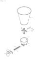
- Fig. 1 is an exploded perspective view showing one embodiment of a stirring and feeding apparatus of the present invention.
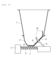
- Fig. 2 is a partial cross-sectional view of one embodiment of the stirring and feeding apparatus of the present invention.
- a connecting tank having an approximately hemispherical inner circumferential surface is provided between a hopper and a discharge portion, and in the connecting tank, a shaft that vertically rotates around a rotation shaft that horizontally protrudes inwards from the inner circumferential surface of the connecting tank is provided, and a stirring blade for stirring a fibrous filler is provided at the tip of the shaft such that the stirring blade vertically rotates along the inner circumferential surface of the connecting tank.
- the stirring and feeding apparatus of the present invention includes a hopper 1 in which a fibrous filler is stored, a connecting tank 2 having an approximately hemispherical inner circumferential surface below the hopper 1, a screw 5 that supplies the fibrous filler to a discharge portion 3 from an opening portion 6 at the bottom portion of the connecting tank 2, and the like.
- the hopper 1 may be conical as shown in Fig. 1 or cylindrical.
- the connecting tank 2 needs to be approximately hemispherical and may have a curved surface, such as an ellipsoidal shape, in a part as long as the revolving stirring blade 10 does not come into contact with the connecting tank 2.
- An agitator 4 is provided in the connecting tank 2, and the agitator 4 is provided with a shaft 9 that vertically rotates around a rotation shaft 8 that horizontally protrudes inwards from the inner circumferential surface of the connecting tank 2 and the stirring blade 10 for stirring the fibrous filler at the tip of the shaft 9 such that the stirring blade 10 vertically rotates (swivels) along the inner circumferential surface of the connecting tank 2.
- the fibrous filler stored in the hopper 1 drops into the connecting tank 2 due to gravity and is stirred and spread by the vertical rotation (swiveling) of the stirring blade 10 provided at the front of the shaft 9 in the agitator 4.
- Fig. 3 shows one embodiment of the stirring blade in the agitator 4
- Fig. 3(a) is the plan view
- Fig. 3(b) is the right-side view.
- the shaft 9 that horizontally extends in Fig. 3(a) and stirring blades 10 at the tips thereof are omitted.
- the stirring blades 10 may extend on the same surface side of the shaft 9 as shown in Fig. 3 or may alternately extend from the front side and the rear side as shown in Fig. 2 . In a case where there are a plurality of the shafts 9, it is preferable that, for example, the stirring blades 10 are provided alternately on the front side, on the rear side, and the front side of the rotation surface of the shafts 9 in order as shown in Fig. 3(a) .
- the stirring blade 10 is inclined inwards with respect to a rotation direction D (the tangential direction of the revolving circumference) of the stirring blade 10 such that the angle thereof becomes an angle ⁇ in the direction of the rotation shaft 8, and the angle ⁇ is set to 10° to 70°.
- a rotation direction D the tangential direction of the revolving circumference
- the angle ⁇ is set to 10° to 70°.
- the angle ⁇ is smaller than 10°, the force for conveying the fibrous filler to a cylinder 7 becomes weak, it is not possible to load a sufficient amount of the fibrous filler into the screw 5 for feeding the fibrous filler to the discharge portion 3 from the bottom portion of the connecting tank 2, and uniform feeding with the screw becomes difficult.
- the angle ⁇ is larger than 70°, the force that is applied to the rotation shaft of the agitator becomes too strong, and the rotation shaft is likely to be damaged.
- the angle ⁇ is more preferably within a range of 20° to 60°.
- the angle ⁇ is preferably 20° or more and is preferably 60° or less and more preferably 50° or less.
- the stirring blade 10 extends along the approximately hemispherical inner circumferential surface of the connecting tank 2, and the shortest distance of the gap between the stirring blade 10 and the inner circumferential surface of the connecting tank is preferably set within a range of 0.2 to 5 cm and more preferably 0.3 to 3 cm.
- the shortest distance is larger than 5 cm, the force for pressing the fibrous filler into the cylinder 7 becomes weak, it is difficult to load a sufficient amount of the fibrous filler into the cylinder 7, and uniform feeding with the screw 5 is likely to be difficult.
- the stirring blade 10 comes into contact with the inner surface of the hopper, and there is a possibility of the agitator 4 being damaged.
- examples of the fibrous filler include inorganic fibers such as carbon fiber, glass fiber, alumina fiber, boron fiber, and ceramic fiber; organic fibers such as plant fiber (including kenaf and bamboo fiber), polyester fiber, aramid fiber, polyoxymethylene fiber, aromatic polyamide fiber, polyparaphenylene benzobisoxazole fiber, and ultra-high-molecular-weight polyethylene fiber; and the like.
- inorganic fibers such as carbon fiber, glass fiber, alumina fiber, boron fiber, and ceramic fiber
- organic fibers such as plant fiber (including kenaf and bamboo fiber), polyester fiber, aramid fiber, polyoxymethylene fiber, aromatic polyamide fiber, polyparaphenylene benzobisoxazole fiber, and ultra-high-molecular-weight polyethylene fiber
- organic fibers such as plant fiber (including kenaf and bamboo fiber), polyester fiber, aramid fiber, polyoxymethylene fiber, aromatic polyamide fiber, polyparaphenylene benzobisoxazole fiber, and ultra-
- the number-average fiber length of the fibrous filler being used is preferably 20 mm or shorter, furthermore, 10 mm or shorter and 1 mm or longer. Specifically, chopped fibers and milled fibers are preferable.
- the bulk density V 0 of the raw material fibrous filler that is stored in the hopper is preferably 0.3 to 0.7 g/cm 3 , more preferably 0.35 to 0.65 g/cm 3 , and still more preferably within a range of 0.4 to 0.6 g/cm 3 .
- the bulk density V 0 is 0.3 /cm 3 or lower, it becomes impossible for the stirring blade to press a sufficient amount of a raw material having a bulk density that is increased by stirring into the cylinder, and uneven feeding is likely to occur.
- the bulk density V 0 exceeds 0.7 g/cm 3 , a strong force is applied to the rotation shaft in the agitator, and the rotation shaft is likely to be damaged.
- a substance that is easy to spread and easily becomes bulkier (has a decreased bulk density) by stirring is suitably used as the fibrous filler, which is a raw material, since the effect of the present invention is large.
- the fibrous filler that easily becomes bulkier by stirring include fibrous fillers for which a sizing agent or the like is not used or which has been treated only to a small extent.
- the bulk density represents the weight of the fibrous filler per certain volume, is the same as the aerated bulk specific gravity, the aerated bulk density, or the aerated apparent density, and refers to the bulk density when the fibrous filler is lightly and quietly loaded into a receiver.
- the bulk densities (V 0 and V 1 ) are values measured on the basis of a measuring method in accordance with ISO 60.
- a metal cylinder having a volume of 100 cc, an inner diameter of 50 mm, and a smoothly-finished inner surface is used as a receiver into which the fibrous filler is to be loaded, the fibrous filler is quietly and slowly loaded into the receiver, once the receiver is fully filled, the raw material swelling out from the receiver is scraped off with a linear plate, the weight of the content in the receiver is measured up to one decimal place, and the bulk density is obtained.
- the fibrous filler spread and stirred with the agitator 4 comes out from the opening portion 6 provided at the bottom portion of the connecting tank 2 and is supplied to the discharge portion 3 with the screw 5, which is intended to feed the fibrous filler to the discharge portion 3.
- the screw 5 may be a single screw or may be composed of a twin screw.
- the screw 5 is disposed in the cylinder 7, the fibrous filler from the opening portion 6 is loaded into the cylinder 7, and the screw 5 is driven to rotate to feed the fibrous filler to the discharge portion 3.
- the opening portion 6 has a rectangular shape that corresponds to the screw 5 that is present immediately below the opening portion 6, and the center line of the opening portion 6 in the longitudinal direction is preferably matched to the rotation shaft 8 in the agitator 4 that is present immediately above the opening portion 6.
- the stirring blade 10 at an inclination angle of 10° to 70° rotates above the inner circumferential surface of the connecting tank 2, and the fibrous filler is sufficiently pressed into the cylinder 7 in which the screw 5 is present from the opening portion 6, which makes uniform feeding of the fibrous filler having a decreased bulk density possible.
- An area obtained by multiplying the area of one stirring blade 10 by cos ⁇ of the inclination angle is preferably within a range of 0.1 times to 1.0 time and more preferably within a range of 0.2 times to 0.8 times the opening area of the opening portion 6 seen from immediately above.
- the area is smaller than 0.1 times, the force for pressing the fibrous filler into the cylinder 7 becomes weak, it is not possible to load a sufficient amount of the fibrous filler into the cylinder 7, and uniform feeding with the screw 5 is likely to be difficult.
- the area is larger than 1.0 time, the force that is applied to the agitator 4 becomes strong, and the rotation shaft 8 is likely to be damaged.
- the area obtained by multiplying the area of one stirring blade 10 by cos ⁇ of the inclination angle is preferably approximately 10 to 350 cm 2 .
- the rotation speed of the agitator 4 is preferably 1% to 20%, more preferably 2% to 15%, and still more preferably 3% to 10% of the rotation speed of the screw 5.
- the rotation speed is less than 1%, the amount of the fibrous filler that is pressed into with the agitator 4 becomes small, and uniform feeding is likely to be difficult.
- the rotation speed exceeds 20%, the fibrous filler is excessively spread, fabric balls are generated, it becomes difficult for the fibrous filler to be pressed into the cylinder 7, it is not possible to load a sufficient amount of the fibrous filler into the cylinder 7, and uniform feeding with the screw 5 is likely to be difficult.
- the rotation speed of the screw 5 is preferably approximately 10 to 600 rpm, and the rotation speed of the agitator 4 is preferably approximately 2 to 90 rpm.
- the lead of the screw 5 is preferably 0.5D to 1.5D.
- the lead of the screw 5 is more preferably 0.6D to 1.4D and still more preferably 0.7D to 1.3D.
- the bulk density V 1 of the fibrous filler supplied to the discharge portion 3 becomes smaller than the bulk density V 0 of the fibrous filler that is stored in the hopper (preferably 0.3 to 0.7 g/cm 3 ) and is preferably within a range of 0.1 to 0.5 g/cm 3 , more preferably 0.15 to 0.45 g/cm 3 , and still more preferably within a range of 0.2 to 0.4 g/cm 3 .
- the fibrous filler is spread and stirred with the agitator having the above-described configuration, conveyed into the screw 5, and fed to the discharge portion 3, which makes it possible to obtain a fibrous filler that has been spread and has a low bulk density.
- a single-screw or twin-screw extruder particularly, a twin-screw extruder is preferable, and any of a vented screw or an unvented screw may be used, but a vented screw is preferable.
- a raw material containing the thermoplastic resin and an additive for a resin that is blended as necessary is fed into a cylinder from a main feeding port of a hopper at the base of the extruder (not shown) in a pellet or powder form and transported to a first kneading portion.
- the raw material is heated in the first kneading portion, and the heating temperature is set based on the melting point, glass transition temperature or the like of the thermoplastic resin, which is a main component.
- the raw material melt-kneaded in the first kneading portion is further pressed against a resin to be supplied later.
- the fibrous filler obtained in the stirring and feeding apparatus is fed into the cylinder of the extruder from a side feeder provided downstream of the main feeding port and melt-kneaded in a second kneading portion.
- the screw configuration in the kneading portion is preferably a combination of two or more elements selected from a forward conveying kneading disc, a reverse conveying kneading disc, and an orthogonal kneading disc.
- the forward conveying kneading disc element is also referred to as an R kneading (hereinafter, also referred to as R in some cases) and normally has two or more blades, and the blade twist angle is preferably 10° to 75°.
- R kneading hereinafter, also referred to as R in some cases
- the blade twist angle is preferably 10° to 75°.
- the reverse conveying kneading disc element is also referred to as an L kneading (hereinafter, also referred to as L in some cases) and normally has two or more blades, and the blade twist angle is preferably -10° to -75°.
- the reverse conveying kneading disc element is an element with a compression capability that holds the incoming resin back or works the incoming resin in the conveying-back direction and is an element that is provided downstream of an element that promotes kneading to hold the resin back and make a strong kneading effect be exhibited.
- the orthogonal kneading disc element is also referred to as an N kneading (hereinafter, also referred to as N in some cases) and normally has two or more blades, and the blade twist angle is 75° to 105°. Since the blades are installed to be twisted at substantially 90°, the force for conveying the resin is weak, but the kneading power is strong.
- the screw configuration in the first kneading portion is preferably composed of a combination of two or more elements, and it is preferable that an element that promotes kneading is disposed upstream and an element with a compression capability is disposed downstream. Therefore, in the kneading zone of a first step, it is preferable to dispose two or more selected from R, N, and L in the order of R, N, and L from the upstream side, and it is also preferable that the number of each of R, N, and L disposed is plural.
- the screw in the second kneading portion is preferably composed of an element selected from the forward conveying kneading disc (R), the reverse conveying kneading disc (L), the orthogonal kneading disc (N), a forward conveying notched mixing screw, and a reverse conveying notched mixing screw.
- a resin composition that has been melt-kneaded in the second kneading portion and contains the fibrous filler sufficiently dispersed therein is extruded in a strand shape from the nozzle at the tip of the extruder, cooled, and then cut with a cutter, whereby pellets of the thermoplastic resin composition are produced.
- Figs. 4 to 6 are view for describing another embodiment of the present invention in which a circular inclined surface is provided at the lower portion of the connecting tank diagonally upwards from the lower portion of the connecting tank, a shaft that rotates around a rotation shaft that protrudes inwards from the center of the circular inclined surface is provided, and a stirring blade for stirring the fibrous filler is provided at the tip of the shaft such that the stirring blade rotates over the circular inclined surface.
- a stirring and feeding apparatus includes a hopper 1 in which fibrous filler is stored, a connecting tank 2 below the hopper 1, a screw 5 that supplies the fibrous filler to a discharge portion 3 from an opening portion 6 at the bottom portion of the connecting tank 2, and the like.
- the hopper 1 is preferably conical as shown in Fig. 4 or cylindrical, but may be prismatic.
- the connecting tank 2 is connected to the hopper 1 at the upper portion, and the side wall of the connecting tank 2 may form a conical shape that is circular in a plan view or may form a cross-sectional shape that is elliptical in a plan view and is the same or different vertically. It is also preferable that the side wall of the connecting tank 2 has a cross-sectional shape that is larger in the lower side than in the upper side.
- a circular inclined surface 11 is provided diagonally upwards from the lower portion, preferably the bottom portion, of the connecting tank, and an agitator 4 in which a shaft 9 that rotates around a rotation shaft 8 that protrudes inwards in an inclined direction from the center of the circular inclined surface 11 is provided, and a stirring blade 10 for stirring the fibrous filler is provided at the tip of the shaft 9 such that the stirring blade rotates over the circular inclined surface 11 is provided.
- Fig. 6 shows one embodiment of a stirring blade in the agitator 4
- Fig. 6(a) is a plan view
- Fig. 6(b) is the right-side view
- Fig. 6(c) is the front view.
- the shaft 9 that horizontally extends in Fig. 6(a) and stirring blades 10 at the tips thereof are omitted.
- the shafts 9 that extend horizontally and backwards and stirring blades 10 at the tips thereof are omitted.
- two shafts may bond to each other at the rotation shaft 8 to form a cross shape, and a total of four stirring blades 10 may be provided.
- three shafts may intersect and bond to one another at the rotation shaft 8, and a total of six stirring blades 10 may be provided at the tips thereof point-symmetrically with respect to the rotation shaft 8 as the central point.
- Three shafts 9 may extend radially from the center of the rotation shaft 8 at intervals of 120°, and a total of three stirring blades 10 may be provided at the tips thereof (one stirring blade per shaft).
- One stirring blade may be provided at each of both ends of one shaft 9.
- the number of the stirring blades 10 is preferably two to six.
- the stirring blade 10 extends toward above the inclined surface 11 from the shaft 9 along the side wall of the connecting tank 2 as shown in Fig. 6(b) .
- the stirring blade 10 is inclined inwards with respect to a rotation direction D (the tangential direction of the revolving circumference) of the stirring blade 10 such that the angle thereof becomes an angle ⁇ in the direction of the rotation shaft 8, and the angle ⁇ is set to 10° to 70°.
- a rotation direction D the tangential direction of the revolving circumference
- the angle ⁇ is set to 10° to 70°.
- the angle ⁇ is smaller than 10°, the force for conveying the fibrous filler to a cylinder 7 becomes weak, it is not possible to load a sufficient amount of the fibrous filler into the screw 5 for feeding the fibrous filler to the discharge portion 3 from the bottom portion of the connecting tank 2, and uniform feeding with the screw becomes difficult.
- the angle ⁇ is larger than 70°, the force that is applied to the rotation shaft of the agitator becomes too strong, and the rotation shaft is likely to be damaged.
- the angle ⁇ is more preferably within a range of 20° to 60°.
- the angle ⁇ is preferably 20° or more and is preferably 60° or less and more preferably 50° or less.
- the stirring blade 10 rotates over the inclined surface 11 along the side wall of the connecting tank 2, and the shortest distance of the gap between the stirring blade 10 and the inner wall surface of the connecting tank is preferably set within a range of 0.2 to 5 cm and more preferably 0.3 to 3 cm.
- the shortest distance is larger than 5 cm, the force for pressing the fibrous filler into the cylinder 7 becomes weak, it is difficult to load a sufficient amount of the fibrous filler into the cylinder 7, and uniform feeding with the screw 5 is likely to be difficult.
- the stirring blade 10 comes into contact with the inner surface of the hopper, and there is a possibility of the agitator 4 being damaged.
- the connecting tank 2 is preferably conical that is circular in a plan view or elliptical in a plan view, but the diameter of the inner wall surface is normally 15 to 60 cm and preferably 20 to 50 cm.
- the diameter of the inclined surface 11 is preferably 15 to 60 cm and more preferably 20 to 50 cm.
- the length from the rotation shaft 8 of the shaft 9 to the connecting portion of the stirring blade 10 is preferably 8 to 30 cm and more preferably 10 to 25 cm.
- the fibrous filler is spread and stirred with the agitator 4 comes out from the opening portion 6 provided at the bottom portion of the connecting tank 2 and is supplied to the discharge portion 3 with the screw 5, which is intended to feed the fibrous filler to the discharge portion 3.
- the opening portion 6 is provided at a position where the stirring blade 10 presses the fibrous filler in from immediately above between the bottom portion of the connecting tank 2 and the inclined surface 11.
- the screw 5 may be a single screw or may be composed of a twin screw.
- the screw 5 is disposed in the cylinder 7, the fibrous filler from the opening portion 6 is loaded into the cylinder 7, and the screw 5 is driven to rotate to feed the fibrous filler to the discharge portion 3.
- the long side is approximately 8 to 25 cm and the short side is approximately 4 to 15 cm, and the opening area is preferably approximately 35 to 350 cm 2 .
- the area obtained by multiplying the area of one stirring blade 10 by cos ⁇ of the inclination angle is preferably approximately 5 to 350 cm 2 .
- the rotation speed of the agitator 4 is preferably 1% to 20%, more preferably 2% to 15%, and still more preferably 3% to 10% of the rotation speed of the screw 5.
- the rotation speed is less than 1% thereof, the amount of the fibrous filler that is pressed into with the agitator 4 becomes small, and uniform feeding is likely to be difficult.
- the rotation speed exceeds 20%, the fibrous filler is excessively spread, fabric balls are generated, it becomes difficult for the fibrous filler to be pressed into the cylinder 7, it is not possible to load a sufficient amount of the fibrous filler into the cylinder 7, and uniform feeding with the screw 5 is likely to be difficult.
- the rotation speed of the screw 5 is preferably approximately 10 to 600 rpm, and the rotation speed of the agitator 4 is preferably approximately 2 to 90 rpm.
- the lead of the screw 5 is preferably 0.5D to 1.5D.
- the lead is larger than 1.5D, the force for transporting the fibrous filler becomes weak, and uniform feeding is likely to be difficult. Even when lead is smaller than 0.5D, the force for transporting the fibrous filler becomes weak, and uniform feeding with the screw 5 is likely to be difficult.
- the lead of the screw 5 is more preferably 0.6D to 1.4D and still more preferably 0.7D to 1.3D.
- Example 1 Operation was performed in the same manner as in Example 1 except that, in Example 1, the agitator (A1) was changed to an agitator (A2) having a total of two stirring blades 10 inclined at 30° in the rotation direction on the front side and the rear side of the shaft surface at both ends of one shaft 9.
- the area of one stirring blade 10 was 47.8 cm 2
- a twin screw extruder "TEX44 ⁇ II" manufactured by The Japan Steel Works, Ltd. was used as an extruder.
- the screw configurations were RRNNL in a first kneading portion and RNL in a second kneading portion.
- R is a forward conveying kneading disc
- N is an orthogonal kneading disc
- L is a reverse conveying kneading disc
- discs each having five paddles and a length of 44 mm were used.
- the cylinder set temperature was set to 260°C.
- a polybutylene terephthalate resin "NOVADURAN 5008" manufactured by Mitsubishi Engineering-Plastics Corporation was used, fed to the screw root with a belt feeder at 180 kg/h, and melted in the first kneading portion.
- a side feed screw was installed between the first kneading portion and the second kneading portion, the chopped carbon fiber "K6371T” obtained by the method of Example 1 was fed at 20 kg/h and kneaded in the second kneading portion.
- the screw rotation speed was set to 250 rpm.
- a strand was taken out from a die, cooled in a water tank, and cut with a pelletizer, thereby obtaining pellets.
- Production was performed in the same manner as in Production Example 1 except that the carbon fiber obtained in Comparative Example 2 was fed instead of the chopped carbon fiber.
- the torque fluctuation was large, over-torquing occurred once every hour, and the extruder was stopped. In addition, the strand broke three times. It was well found that the weight of the carbon fiber taken out from one gram was 0.089 g and the feeding of the chopped carbon fiber had fluctuated.
Landscapes
- Engineering & Computer Science (AREA)
- Mechanical Engineering (AREA)
- Chemical & Material Sciences (AREA)
- Chemical Kinetics & Catalysis (AREA)
- Dispersion Chemistry (AREA)
- Composite Materials (AREA)
- Processing And Handling Of Plastics And Other Materials For Molding In General (AREA)
- Extrusion Moulding Of Plastics Or The Like (AREA)
Abstract
A stirring and feeding apparatus of a fibrous filler enables even a fibrous filler that is easy to spread, that has a low bulk density, and that is easy to flocculate to be uniformly and stably transported with a screw.
A stirring and feeding apparatus for feeding a fibrous filler from a hopper storing the fibrous filler to a discharge portion, comprises:
a connecting tank between the hopper and the discharge portion,
wherein, in the connecting tank, a shaft that rotates around a rotation shaft is provided, and a stirring blade for stirring the fibrous filler is provided at a tip of the shaft such that the stirring blade rotates along an inner circumferential surface of the connecting tank, and the stirring blade is inclined inwards at an angle θ of 10° to 70° with respect to a rotation direction of the stirring blade.
a connecting tank between the hopper and the discharge portion,
wherein, in the connecting tank, a shaft that rotates around a rotation shaft is provided, and a stirring blade for stirring the fibrous filler is provided at a tip of the shaft such that the stirring blade rotates along an inner circumferential surface of the connecting tank, and the stirring blade is inclined inwards at an angle θ of 10° to 70° with respect to a rotation direction of the stirring blade.
Description
- The present invention relates to a stirring and feeding apparatus, a feeding method, and a production method of a fibrous filler, and a production method of a thermoplastic resin composition.
- In order to produce a composition of a resin, a method in which a raw material resin and a variety of additives are supplied to an extruder and melt-kneaded to produce pellets of a resin composition is being widely performed. A fiber-reinforced thermoplastic resin composition, into which a fibrous filler such as a carbon fiber or a glass fiber has been blended as an additive, makes the strength of a molded product, which is to be obtained, large, and is being widely used in a variety of fields.
- In order to produce a fiber-reinforced thermoplastic resin composition, the resin pellets of a thermoplastic resin, which is a raw material, are supplied to an extruder, and the resin pellets are melted in the cylinder of the extruder and conveyed forward (downstream) with a screw. A fibrous filler is supplied into the cylinder with a side feeder at a predetermined position in the cylinder of the extruder. In the extruder, the molten thermoplastic resin and the fibrous filler are kneaded together by the rotation of the screw, and the fibrous filler is dispersed into pieces, appropriately cut, extruded from the tip nozzle, then, cooled and cut, whereby pellets of the fiber-reinforced thermoplastic resin composition are produced.
- In a case where a variety of additives are supplied from the side feeder, a stirring and feeding apparatus, composed of a hopper (measuring tank) that stores raw material additives, a connecting tank below the hopper, an agitator that stirs raw materials in the connecting tank, and a screw cylinder having a screw for conveying the additives to a discharge portion at the bottom portion of the connecting tank, is provided.
- Normally, the fibrous filler is provided as chopped fibers. When such a fibrous filler is supplied, as it is, to the extruder cylinder from the side feeder, stress that is applied to the fibrous filler during kneading with the thermoplastic resin becomes nonuniform, and the fibrous filler is likely to be broken or cut, and moreover the fiber length distribution in the thermoplastic resin composition becomes nonuniform.
- However, an agitator in a conventional stirring and feeding apparatus is configured to stir raw materials in the connecting tank and is intended to suppress bridging in which part or all of the fibrous filler no longer falls into the connecting tank or a phenomenon in which only the central part of the fibrous falls off. However, when the fibrous filler has a small bulk density and is easy to spread, it is not possible to stably feed fibers to the cylinder with the screw. A fibrous filler that is easy to spread is easily spread and flocculated by being charged into the hopper (measuring tank), and moved downward, and moreover rotated with the agitator, thereby forming a bridge at the cylinder opening portion without dropping into the cylinder. Therefore, the fibrous filler cannot be sufficiently loaded into the cylinder, and uniform transport with the screw is difficult.
- An object of the present invention is to provide a stirring and feeding apparatus of a fibrous filler and a feeding method of a fibrous filler that enable uniform and stable transport with a screw of even a fibrous filler that is easy to spread, that has a low bulk density, and that is easy to flocculate in consideration of the above-described problem of the related art. In addition, another object of the present invention is to provide a production method of a fibrous filler for which spreading has been promoted and bulk density has been reduced by the stirring and feeding apparatus or the feeding method and a method for stably producing a thermoplastic resin composition into which a fibrous filler obtained by the above-described production method has been blended.
- In order to achieve the above-described objects, a stirring and feeding apparatus of a fibrous filler of the present invention is a apparatus for feeding a fibrous filler from a hopper storing the fibrous filler to a discharge portion, the stirring and feeding apparatus including: a connecting tank between the hopper and the discharge portion, wherein, in the connecting tank, a shaft that rotates around a rotation shaft is provided, and a stirring blade for stirring the fibrous filler is provided at a tip of the shaft such that the stirring blade rotates along an inner circumferential surface of the connecting tank, and the stirring blade is inclined inwards at an angle θ of 10° to 70° with respect to a rotation direction of the stirring blade.
- It is preferable that the stirring and feeding apparatus of a fibrous filler includes a connecting tank having an approximately hemispherical inner circumferential surface between the hopper and the discharge portion, in the connecting tank a shaft that vertically rotates around a rotation shaft that horizontally protrudes inwards from the inner circumferential surface of the connecting tank is provided, and a stirring blade for stirring the fibrous filler is provided at a tip of the shaft such that the stirring blade vertically rotates along the inner circumferential surface of the connecting tank, and the stirring blade is inclined inwards at an angle θ of 10° to 70° with respect to a rotation direction of the stirring blade. In the stirring and feeding apparatus, a shortest distance of a gap between the stirring blade and the inner circumferential surface of the connecting tank is preferably within a range of 0.2 to 5 cm.
- It is preferable that the stirring and feeding apparatus of a fibrous filler includes a connecting tank between the hopper and the discharge portion, a circular inclined surface is provided at a lower portion of the connecting tank diagonally upwards from the lower portion of the connecting tank, a shaft that rotates around a rotation shaft that protrudes inwards from a center of the circular inclined surface is provided, a stirring blade for stirring the fibrous filler is provided at a tip of the shaft such that the stirring blade rotates over the circular inclined surface, and the stirring blade is inclined inwards at an angle θ of 10° to 70° with respect to a rotation direction of the stirring blade. A shortest distance of a gap between the tip of the stirring blade and an inner wall surface of the connecting tank is preferably within a range of 0.2 to 5 cm.
- The number of the stirring blades is preferably two to six.
- At a bottom portion of the connecting tank, a screw for feeding the fibrous filler to the discharge portion is preferably provided.
- An area obtained by multiplying an area of each stirring blade by cosθ of an inclination angle is preferably within a range of 0.1 times to 1.0 time an opening area of an opening portion at the bottom portion of the connecting tank toward the screw when seen from immediately above.
- A feeding method of a fibrous filler of the present invention is a method for feeding a fibrous filler stored in a hopper to a discharge portion, wherein a connecting tank is provided between the hopper and the discharge portion, in the connecting tank an agitator, in which a shaft that rotates around a rotation shaft is provided, a stirring blade for stirring the fibrous filler is provided at a tip of the shaft such that the stirring blade rotates along an inner circumferential surface of the connecting tank, and the stirring blade is inclined inwards at an angle θ of 10° to 70° with respect to a rotation direction of the stirring blade, is provided, and the fibrous filler is spread with the agitator and supplied to the discharge portion with a screw provided at a bottom portion of the connecting tank.
- In the feeding method, a rotation speed of the agitator is preferably 1% to 20% of a rotation speed of the screw.
- It is preferable that a bulk density V0 of the fibrous filler that is stored in the hopper is 0.3 to 0.7 g/cm3 and a bulk density V1 of the discharged fibrous filler is within a range of 0.1 to 0.5 g/cm3 that is smaller than V0.
- A production method of a fibrous filler of the present invention is a method for producing a fibrous filler having a bulk density decreased by spreading the fibrous filler stored in a hopper, wherein a connecting tank is provided between the hopper and the discharge portion, in the connecting tank an agitator, in which a shaft that rotates around a rotation shaft is provided, a stirring blade for stirring the fibrous filler is provided at a tip of the shaft such that the stirring blade rotates along an inner circumferential surface of the connecting tank, and the stirring blade is inclined inwards at an angle θ of 10° to 70° with respect to a rotation direction of the stirring blade, is provided, and the fibrous filler is spread with the agitator and supplied to the discharge portion with a screw provided at a bottom portion of the connecting tank.
- Here, it is preferable that a bulk density V0 of the fibrous filler that is stored in the hopper is 0.3 to 0.7 g/cm3 and a bulk density V1 of the discharged fibrous filler is within a range of 0.1 to 0.5 g/cm3 that is smaller than V0.
- A production method of a thermoplastic resin composition is a method for producing a thermoplastic resin composition containing a fibrous filler blended into a thermoplastic resin with an extruder, wherein a fibrous filler having a decreased bulk density obtained by the production method of a fibrous filler is side-fed from a side feeder provided downstream of a main feeding port of a raw material containing the thermoplastic resin and melt-kneaded.
- According to the stirring and feeding apparatus of a fibrous filler of the present invention, it is possible to enable even a fibrous filler that is easy to spread, has a low bulk density, and is easy to flocculate to be uniformly and stably transported with a screw.
- In addition, according to the feeding method of a fibrous filler of the present invention, it is possible to enable even a fibrous filler that is easy to spread and has a low bulk density to be stably supplied to a discharge portion.
- In addition, according to the production method of a fibrous filler of the present invention, it is possible to stably produce a fibrous filler that has been spread and has a decreased bulk density.
- In addition, according to the production method of a thermoplastic resin composition of the present invention, it is possible to stably produce a thermoplastic resin composition in which a fibrous filler has been uniformly dispersed.
-
- [
Fig. 1 ]
Fig. 1 is an exploded perspective view showing one embodiment of a stirring and feeding apparatus of the present invention. - [
Fig. 2 ]
Fig. 2 is a partial cross-sectional view of one embodiment of the stirring and feeding apparatus of the present invention. - [
Fig. 3 ]
Fig. 3 is a plan view and a side view showing one embodiment of a stirring blade that is used in the stirring and feeding apparatus of the present invention. - [
Fig. 4 ]
Fig. 4 is an exploded perspective view showing an embodiment having a circular inclined surface at a lower portion of a connecting tank. - [
Fig. 5 ]
Fig. 5 is a partial cross-sectional view of the embodiment having the circular inclined surface ofFig. 4 . - [
Fig. 6 ]
Fig. 6 is a plan view and a side view showing one embodiment of a stirring blade that is used in the case of having the circular inclined surface ofFig. 4 . - Hereinafter, a stirring and feeding apparatus, a feeding method, and a production method of a fibrous filler, and a production method of a thermoplastic resin composition of the present invention will be described with reference to drawings. Embodiments to be described below are merely examples, and the present invention is not necessarily limited thereto.
-
Fig. 1 is an exploded perspective view showing one embodiment of a stirring and feeding apparatus of the present invention.Fig. 2 is a partial cross-sectional view of one embodiment of the stirring and feeding apparatus of the present invention. InFigs. 1 and2 , a connecting tank having an approximately hemispherical inner circumferential surface is provided between a hopper and a discharge portion, and in the connecting tank, a shaft that vertically rotates around a rotation shaft that horizontally protrudes inwards from the inner circumferential surface of the connecting tank is provided, and a stirring blade for stirring a fibrous filler is provided at the tip of the shaft such that the stirring blade vertically rotates along the inner circumferential surface of the connecting tank. - As shown in
Figs. 1 and2 , the stirring and feeding apparatus of the present invention includes ahopper 1 in which a fibrous filler is stored, a connectingtank 2 having an approximately hemispherical inner circumferential surface below thehopper 1, ascrew 5 that supplies the fibrous filler to adischarge portion 3 from anopening portion 6 at the bottom portion of the connectingtank 2, and the like. Thehopper 1 may be conical as shown inFig. 1 or cylindrical. The connectingtank 2 needs to be approximately hemispherical and may have a curved surface, such as an ellipsoidal shape, in a part as long as the revolving stirringblade 10 does not come into contact with the connectingtank 2. - An
agitator 4 is provided in the connectingtank 2, and theagitator 4 is provided with ashaft 9 that vertically rotates around arotation shaft 8 that horizontally protrudes inwards from the inner circumferential surface of the connectingtank 2 and thestirring blade 10 for stirring the fibrous filler at the tip of theshaft 9 such that thestirring blade 10 vertically rotates (swivels) along the inner circumferential surface of the connectingtank 2. - The fibrous filler stored in the
hopper 1 drops into the connectingtank 2 due to gravity and is stirred and spread by the vertical rotation (swiveling) of thestirring blade 10 provided at the front of theshaft 9 in theagitator 4. -
Fig. 3 shows one embodiment of the stirring blade in theagitator 4,Fig. 3(a) is the plan view, andFig. 3(b) is the right-side view. InFig. 3(b) , theshaft 9 that horizontally extends inFig. 3(a) and stirringblades 10 at the tips thereof are omitted. - In the
shaft 9, as shown inFig. 3(a) , two shafts may bond to each other at therotation shaft 8 to form a cross shape, and a total of four stirringblades 10 may be provided. In addition, three shafts may intersect and bond to one another at therotation shaft 8, and a total of sixstirring blades 10 may be provided at the tips thereof point-symmetrically with respect to therotation shaft 8 as the central point. Threeshafts 9 may extend radially from the center of therotation shaft 8 at intervals of 120°, and a total of threestirring blades 10 may be provided at the tips thereof (one stirring blade per shaft). One stirring blade may be provided at each of both ends of oneshaft 9. The number of thestirring blades 10 is preferably two to six. - The stirring
blades 10 may extend on the same surface side of theshaft 9 as shown inFig. 3 or may alternately extend from the front side and the rear side as shown inFig. 2 . In a case where there are a plurality of theshafts 9, it is preferable that, for example, the stirringblades 10 are provided alternately on the front side, on the rear side, and the front side of the rotation surface of theshafts 9 in order as shown inFig. 3(a) . - As shown in
Fig. 3(a) , the stirringblade 10 is inclined inwards with respect to a rotation direction D (the tangential direction of the revolving circumference) of thestirring blade 10 such that the angle thereof becomes an angle θ in the direction of therotation shaft 8, and the angle θ is set to 10° to 70°. When the angle is set as described above, uneven feeding from the bottom portion of the connectingtank 2 to thedischarge portion 3 is suppressed, and uniform feeding becomes possible. When the angle θ is smaller than 10°, the force for conveying the fibrous filler to acylinder 7 becomes weak, it is not possible to load a sufficient amount of the fibrous filler into thescrew 5 for feeding the fibrous filler to thedischarge portion 3 from the bottom portion of the connectingtank 2, and uniform feeding with the screw becomes difficult. When the angle θ is larger than 70°, the force that is applied to the rotation shaft of the agitator becomes too strong, and the rotation shaft is likely to be damaged. The angle θ is more preferably within a range of 20° to 60°. The angle θ is preferably 20° or more and is preferably 60° or less and more preferably 50° or less. - The stirring
blade 10 extends along the approximately hemispherical inner circumferential surface of the connectingtank 2, and the shortest distance of the gap between the stirringblade 10 and the inner circumferential surface of the connecting tank is preferably set within a range of 0.2 to 5 cm and more preferably 0.3 to 3 cm. When the shortest distance is larger than 5 cm, the force for pressing the fibrous filler into thecylinder 7 becomes weak, it is difficult to load a sufficient amount of the fibrous filler into thecylinder 7, and uniform feeding with thescrew 5 is likely to be difficult. When the shortest distance is less than 0.2 cm, the stirringblade 10 comes into contact with the inner surface of the hopper, and there is a possibility of theagitator 4 being damaged. - The connecting
tank 2 is approximately hemispherical, but the diameter of the inner surface at the upper portion thereof is normally 15 to 50 cm and preferably 20 to 40 cm. - In the present invention, examples of the fibrous filler include inorganic fibers such as carbon fiber, glass fiber, alumina fiber, boron fiber, and ceramic fiber; organic fibers such as plant fiber (including kenaf and bamboo fiber), polyester fiber, aramid fiber, polyoxymethylene fiber, aromatic polyamide fiber, polyparaphenylene benzobisoxazole fiber, and ultra-high-molecular-weight polyethylene fiber; and the like. Among these, carbon fiber and glass fiber are preferable, and carbon fiber are particularly preferable.
- The number-average fiber length of the fibrous filler being used is preferably 20 mm or shorter, furthermore, 10 mm or shorter and 1 mm or longer. Specifically, chopped fibers and milled fibers are preferable.
- The bulk density V0 of the raw material fibrous filler that is stored in the hopper is preferably 0.3 to 0.7 g/cm3, more preferably 0.35 to 0.65 g/cm3, and still more preferably within a range of 0.4 to 0.6 g/cm3. When the bulk density V0 is 0.3 /cm3 or lower, it becomes impossible for the stirring blade to press a sufficient amount of a raw material having a bulk density that is increased by stirring into the cylinder, and uneven feeding is likely to occur. When the bulk density V0 exceeds 0.7 g/cm3, a strong force is applied to the rotation shaft in the agitator, and the rotation shaft is likely to be damaged.
- Particularly, in the present invention, a substance that is easy to spread and easily becomes bulkier (has a decreased bulk density) by stirring is suitably used as the fibrous filler, which is a raw material, since the effect of the present invention is large. Examples of the fibrous filler that easily becomes bulkier by stirring include fibrous fillers for which a sizing agent or the like is not used or which has been treated only to a small extent.
- In the present invention, the bulk density represents the weight of the fibrous filler per certain volume, is the same as the aerated bulk specific gravity, the aerated bulk density, or the aerated apparent density, and refers to the bulk density when the fibrous filler is lightly and quietly loaded into a receiver. The bulk densities (V0 and V1) are values measured on the basis of a measuring method in accordance with ISO 60. Specifically, a metal cylinder having a volume of 100 cc, an inner diameter of 50 mm, and a smoothly-finished inner surface is used as a receiver into which the fibrous filler is to be loaded, the fibrous filler is quietly and slowly loaded into the receiver, once the receiver is fully filled, the raw material swelling out from the receiver is scraped off with a linear plate, the weight of the content in the receiver is measured up to one decimal place, and the bulk density is obtained.
- The fibrous filler spread and stirred with the
agitator 4 comes out from theopening portion 6 provided at the bottom portion of the connectingtank 2 and is supplied to thedischarge portion 3 with thescrew 5, which is intended to feed the fibrous filler to thedischarge portion 3. Thescrew 5 may be a single screw or may be composed of a twin screw. Thescrew 5 is disposed in thecylinder 7, the fibrous filler from theopening portion 6 is loaded into thecylinder 7, and thescrew 5 is driven to rotate to feed the fibrous filler to thedischarge portion 3. - The
opening portion 6 has a rectangular shape that corresponds to thescrew 5 that is present immediately below theopening portion 6, and the center line of theopening portion 6 in the longitudinal direction is preferably matched to therotation shaft 8 in theagitator 4 that is present immediately above theopening portion 6. The stirringblade 10 at an inclination angle of 10° to 70° rotates above the inner circumferential surface of the connectingtank 2, and the fibrous filler is sufficiently pressed into thecylinder 7 in which thescrew 5 is present from theopening portion 6, which makes uniform feeding of the fibrous filler having a decreased bulk density possible. - An area obtained by multiplying the area of one
stirring blade 10 by cosθ of the inclination angle is preferably within a range of 0.1 times to 1.0 time and more preferably within a range of 0.2 times to 0.8 times the opening area of theopening portion 6 seen from immediately above. When the area is smaller than 0.1 times, the force for pressing the fibrous filler into thecylinder 7 becomes weak, it is not possible to load a sufficient amount of the fibrous filler into thecylinder 7, and uniform feeding with thescrew 5 is likely to be difficult. When the area is larger than 1.0 time, the force that is applied to theagitator 4 becomes strong, and therotation shaft 8 is likely to be damaged. - Regarding the size of the
opening portion 6, it is preferable that the long side is approximately 10 to 25 cm and the short side is approximately 5 to 15 cm, and the opening area is preferably approximately 50 to 350 cm2. - The area obtained by multiplying the area of one
stirring blade 10 by cosθ of the inclination angle is preferably approximately 10 to 350 cm2. - The rotation speed of the
agitator 4 is preferably 1% to 20%, more preferably 2% to 15%, and still more preferably 3% to 10% of the rotation speed of thescrew 5. When the rotation speed is less than 1%, the amount of the fibrous filler that is pressed into with theagitator 4 becomes small, and uniform feeding is likely to be difficult. When the rotation speed exceeds 20%, the fibrous filler is excessively spread, fabric balls are generated, it becomes difficult for the fibrous filler to be pressed into thecylinder 7, it is not possible to load a sufficient amount of the fibrous filler into thecylinder 7, and uniform feeding with thescrew 5 is likely to be difficult. - The rotation speed of the
screw 5 is preferably approximately 10 to 600 rpm, and the rotation speed of theagitator 4 is preferably approximately 2 to 90 rpm. - The distance that the screw advances in the shaft direction when the screw has rotated once is referred to as "lead", and the lead and the pitch becomes equal to each other in a single-thread screw. In a double-thread screw, the lead becomes twice the pitch. When the screw diameter (outer diameter) is indicated by D, the lead of the
screw 5 is preferably 0.5D to 1.5D. When the lead is larger than 1.5D, the force for transporting the fibrous filler becomes weak, and uniform feeding is likely to be difficult. Even when lead is smaller than 0.5D, the force for transporting the fibrous filler becomes weak, and uniform feeding is likely to be difficult. The lead of thescrew 5 is more preferably 0.6D to 1.4D and still more preferably 0.7D to 1.3D. - The bulk density V1 of the fibrous filler supplied to the
discharge portion 3 becomes smaller than the bulk density V0 of the fibrous filler that is stored in the hopper (preferably 0.3 to 0.7 g/cm3) and is preferably within a range of 0.1 to 0.5 g/cm3, more preferably 0.15 to 0.45 g/cm3, and still more preferably within a range of 0.2 to 0.4 g/cm3. - According to the present invention, in particular, even when a fibrous filler for which a sizing agent or the like is not used or which has been treated only to a small extent is a raw material, the fibrous filler is spread and stirred with the agitator having the above-described configuration, conveyed into the
screw 5, and fed to thedischarge portion 3, which makes it possible to obtain a fibrous filler that has been spread and has a low bulk density. - When the obtained fibrous filler is side-fed to an extruder, it is possible to obtain a fibrous filler enabling a thermoplastic resin composition containing the fibrous filler uniformly dispersed therein to be stably produced.
- The kind of a raw material thermoplastic resin being used is not particularly limited, and any resin may be used as long as the resin is a thermoplastic resin. Examples of a thermoplastic resin suitable for use in the present invention include a crystalline thermoplastic resin or an amorphous thermoplastic resin, and specific examples thereof include polycarbonate resin; polyester resins such as polybutylene terephthalate resin and polyethylene terephthalate resin; styrene resins such as polystyrene resin, high impact polystyrene resin (HIPS), ABS resin, AES resin, and AS resin; polyolefin resins such as polyethylene resin and polypropylene resin; polyamide resins such as
polyamide 6, polyamide 66, and polyamide MXD6; polyoxymethylene resin; polyphenylene sulfide resin; methacrylic resin such as PMMA resin; polyphenylene ether resin; polysulfone resin; polyethersulfone resin; polyarylate resin; polyetherimide resin; polyamideimide resin; polyimide resin; polyetherketone resin; polyetheretherketone resin; polyestercarbonate resin; liquid crystal polymer; and the like. - As the extruder, a single-screw or twin-screw extruder, particularly, a twin-screw extruder is preferable, and any of a vented screw or an unvented screw may be used, but a vented screw is preferable.
- A raw material containing the thermoplastic resin and an additive for a resin that is blended as necessary is fed into a cylinder from a main feeding port of a hopper at the base of the extruder (not shown) in a pellet or powder form and transported to a first kneading portion. The raw material is heated in the first kneading portion, and the heating temperature is set based on the melting point, glass transition temperature or the like of the thermoplastic resin, which is a main component. The raw material melt-kneaded in the first kneading portion is further pressed against a resin to be supplied later. In addition, the fibrous filler obtained in the stirring and feeding apparatus is fed into the cylinder of the extruder from a side feeder provided downstream of the main feeding port and melt-kneaded in a second kneading portion.
- The screw configuration in the kneading portion is preferably a combination of two or more elements selected from a forward conveying kneading disc, a reverse conveying kneading disc, and an orthogonal kneading disc.
- The forward conveying kneading disc element is also referred to as an R kneading (hereinafter, also referred to as R in some cases) and normally has two or more blades, and the blade twist angle is preferably 10° to 75°. When the blades are installed to be twisted at a predetermined angle as described above, a zone in which a pseudo screw structure is formed, a strong shear force is applied to the resin while the resin is conveyed in the conveying direction, and kneading is performed is formed.
- The reverse conveying kneading disc element is also referred to as an L kneading (hereinafter, also referred to as L in some cases) and normally has two or more blades, and the blade twist angle is preferably -10° to -75°. The reverse conveying kneading disc element is an element with a compression capability that holds the incoming resin back or works the incoming resin in the conveying-back direction and is an element that is provided downstream of an element that promotes kneading to hold the resin back and make a strong kneading effect be exhibited.
- The orthogonal kneading disc element is also referred to as an N kneading (hereinafter, also referred to as N in some cases) and normally has two or more blades, and the blade twist angle is 75° to 105°. Since the blades are installed to be twisted at substantially 90°, the force for conveying the resin is weak, but the kneading power is strong.
- The screw configuration in the first kneading portion is preferably composed of a combination of two or more elements, and it is preferable that an element that promotes kneading is disposed upstream and an element with a compression capability is disposed downstream. Therefore, in the kneading zone of a first step, it is preferable to dispose two or more selected from R, N, and L in the order of R, N, and L from the upstream side, and it is also preferable that the number of each of R, N, and L disposed is plural.
- The screw in the second kneading portion is preferably composed of an element selected from the forward conveying kneading disc (R), the reverse conveying kneading disc (L), the orthogonal kneading disc (N), a forward conveying notched mixing screw, and a reverse conveying notched mixing screw.
- A resin composition that has been melt-kneaded in the second kneading portion and contains the fibrous filler sufficiently dispersed therein is extruded in a strand shape from the nozzle at the tip of the extruder, cooled, and then cut with a cutter, whereby pellets of the thermoplastic resin composition are produced. This makes it possible to stably produce a thermoplastic resin composition in which the fibrous filler has been uniformly dispersed.
-
Figs. 4 to 6 are view for describing another embodiment of the present invention in which a circular inclined surface is provided at the lower portion of the connecting tank diagonally upwards from the lower portion of the connecting tank, a shaft that rotates around a rotation shaft that protrudes inwards from the center of the circular inclined surface is provided, and a stirring blade for stirring the fibrous filler is provided at the tip of the shaft such that the stirring blade rotates over the circular inclined surface. - As shown in
Figs. 4 and5 , a stirring and feeding apparatus includes ahopper 1 in which fibrous filler is stored, a connectingtank 2 below thehopper 1, ascrew 5 that supplies the fibrous filler to adischarge portion 3 from anopening portion 6 at the bottom portion of the connectingtank 2, and the like. Thehopper 1 is preferably conical as shown inFig. 4 or cylindrical, but may be prismatic. - The connecting
tank 2 is connected to thehopper 1 at the upper portion, and the side wall of the connectingtank 2 may form a conical shape that is circular in a plan view or may form a cross-sectional shape that is elliptical in a plan view and is the same or different vertically. It is also preferable that the side wall of the connectingtank 2 has a cross-sectional shape that is larger in the lower side than in the upper side. - In the connecting
tank 2, a circularinclined surface 11 is provided diagonally upwards from the lower portion, preferably the bottom portion, of the connecting tank, and anagitator 4 in which ashaft 9 that rotates around arotation shaft 8 that protrudes inwards in an inclined direction from the center of the circularinclined surface 11 is provided, and astirring blade 10 for stirring the fibrous filler is provided at the tip of theshaft 9 such that the stirring blade rotates over the circularinclined surface 11 is provided. - The fibrous filler stored in the
hopper 1 drops into the connectingtank 2 due to gravity and is stirred and spread by the rotation (swiveling) of thestirring blade 10 provided at the front of theshaft 9 in theagitator 4 along theinclined surface 11. -
Fig. 6 shows one embodiment of a stirring blade in theagitator 4,Fig. 6(a) is a plan view,Fig. 6(b) is the right-side view, andFig. 6(c) is the front view. InFig. 6(b) , theshaft 9 that horizontally extends inFig. 6(a) and stirringblades 10 at the tips thereof are omitted. In addition, inFig. 6(c) , theshafts 9 that extend horizontally and backwards and stirringblades 10 at the tips thereof are omitted. - In the
shaft 9, as shown inFig. 6(a) , two shafts may bond to each other at therotation shaft 8 to form a cross shape, and a total of fourstirring blades 10 may be provided. In addition, three shafts may intersect and bond to one another at therotation shaft 8, and a total of sixstirring blades 10 may be provided at the tips thereof point-symmetrically with respect to therotation shaft 8 as the central point. Threeshafts 9 may extend radially from the center of therotation shaft 8 at intervals of 120°, and a total of threestirring blades 10 may be provided at the tips thereof (one stirring blade per shaft). One stirring blade may be provided at each of both ends of oneshaft 9. The number of thestirring blades 10 is preferably two to six. - It is preferable that the stirring
blade 10 extends toward above theinclined surface 11 from theshaft 9 along the side wall of the connectingtank 2 as shown inFig. 6(b) . - As shown in
Fig. 6(c) , the stirringblade 10 is inclined inwards with respect to a rotation direction D (the tangential direction of the revolving circumference) of thestirring blade 10 such that the angle thereof becomes an angle θ in the direction of therotation shaft 8, and the angle θ is set to 10° to 70°. When the angle is set as described above, uneven feeding from the bottom portion of the connectingtank 2 to thedischarge portion 3 is suppressed, and uniform feeding becomes possible. When the angle θ is smaller than 10°, the force for conveying the fibrous filler to acylinder 7 becomes weak, it is not possible to load a sufficient amount of the fibrous filler into thescrew 5 for feeding the fibrous filler to thedischarge portion 3 from the bottom portion of the connectingtank 2, and uniform feeding with the screw becomes difficult. When the angle θ is larger than 70°, the force that is applied to the rotation shaft of the agitator becomes too strong, and the rotation shaft is likely to be damaged. The angle θ is more preferably within a range of 20° to 60°. The angle θ is preferably 20° or more and is preferably 60° or less and more preferably 50° or less. - As shown in
Fig. 5 , the stirringblade 10 rotates over theinclined surface 11 along the side wall of the connectingtank 2, and the shortest distance of the gap between the stirringblade 10 and the inner wall surface of the connecting tank is preferably set within a range of 0.2 to 5 cm and more preferably 0.3 to 3 cm. When the shortest distance is larger than 5 cm, the force for pressing the fibrous filler into thecylinder 7 becomes weak, it is difficult to load a sufficient amount of the fibrous filler into thecylinder 7, and uniform feeding with thescrew 5 is likely to be difficult. When the shortest distance is less than 0.2 cm, the stirringblade 10 comes into contact with the inner surface of the hopper, and there is a possibility of theagitator 4 being damaged. - The connecting
tank 2 is preferably conical that is circular in a plan view or elliptical in a plan view, but the diameter of the inner wall surface is normally 15 to 60 cm and preferably 20 to 50 cm. - The diameter of the
inclined surface 11 is preferably 15 to 60 cm and more preferably 20 to 50 cm. - The length from the
rotation shaft 8 of theshaft 9 to the connecting portion of thestirring blade 10 is preferably 8 to 30 cm and more preferably 10 to 25 cm. - The fibrous filler is spread and stirred with the
agitator 4 comes out from theopening portion 6 provided at the bottom portion of the connectingtank 2 and is supplied to thedischarge portion 3 with thescrew 5, which is intended to feed the fibrous filler to thedischarge portion 3. Theopening portion 6 is provided at a position where thestirring blade 10 presses the fibrous filler in from immediately above between the bottom portion of the connectingtank 2 and theinclined surface 11. - The
screw 5 may be a single screw or may be composed of a twin screw. Thescrew 5 is disposed in thecylinder 7, the fibrous filler from theopening portion 6 is loaded into thecylinder 7, and thescrew 5 is driven to rotate to feed the fibrous filler to thedischarge portion 3. - The
opening portion 6 has a rectangular shape that corresponds to thescrew 5 that is present immediately below theopening portion 6, and thestirring blade 10 at an inclination angle of 10° to 70° sufficiently presses the fibrous filler into thecylinder 7 from theopening portion 6, which makes uniform feeding of the fibrous filler having a decreased bulk density possible. - An area obtained by multiplying the area of one
stirring blade 10 by cosθ of the inclination angle is preferably within a range of 0.1 times to 1.0 time and more preferably within a range of 0.2 times to 0.8 times the opening area of theopening portion 6 seen from immediately above. When the area is smaller than 0.1 times, the force for pressing the fibrous filler into thecylinder 7 becomes weak, it is not possible to load a sufficient amount of the fibrous filler into thecylinder 7, and uniform feeding with thescrew 5 is likely to be difficult. When the area is larger than 1.0 time, the force that is applied to theagitator 4 becomes strong, and therotation shaft 8 is likely to be damaged. - Regarding the size of the
opening portion 6, it is preferable that the long side is approximately 8 to 25 cm and the short side is approximately 4 to 15 cm, and the opening area is preferably approximately 35 to 350 cm2. - The area obtained by multiplying the area of one
stirring blade 10 by cosθ of the inclination angle is preferably approximately 5 to 350 cm2. - The rotation speed of the
agitator 4 is preferably 1% to 20%, more preferably 2% to 15%, and still more preferably 3% to 10% of the rotation speed of thescrew 5. When the rotation speed is less than 1% thereof, the amount of the fibrous filler that is pressed into with theagitator 4 becomes small, and uniform feeding is likely to be difficult. When the rotation speed exceeds 20%, the fibrous filler is excessively spread, fabric balls are generated, it becomes difficult for the fibrous filler to be pressed into thecylinder 7, it is not possible to load a sufficient amount of the fibrous filler into thecylinder 7, and uniform feeding with thescrew 5 is likely to be difficult. - The rotation speed of the
screw 5 is preferably approximately 10 to 600 rpm, and the rotation speed of theagitator 4 is preferably approximately 2 to 90 rpm. - The distance that the screw advances in the shaft direction when the screw has rotated once is referred to as "lead", and the lead and the pitch becomes equal to each other in a single-thread screw. In a double-thread screw, the lead becomes twice the pitch. When the screw diameter (outer diameter) is indicated by D, the lead of the
screw 5 is preferably 0.5D to 1.5D. When the lead is larger than 1.5D, the force for transporting the fibrous filler becomes weak, and uniform feeding is likely to be difficult. Even when lead is smaller than 0.5D, the force for transporting the fibrous filler becomes weak, and uniform feeding with thescrew 5 is likely to be difficult. The lead of thescrew 5 is more preferably 0.6D to 1.4D and still more preferably 0.7D to 1.3D. - The bulk density V1 of the fibrous filler supplied to the
discharge portion 3 becomes smaller than the bulk density V0 of the fibrous filler that is stored in the hopper (preferably 0.3 to 0.7 g/cm3) and is preferably within a range of 0.1 to 0.5 g/cm3, more preferably 0.15 to 0.45 g/cm3, and still more preferably within a range of 0.2 to 0.4 g/cm3. - Even in a case where the circular inclined surface is provided at the lower portion of the connecting tank diagonally upwards from the lower portion of the connecting tank, according to the present invention, in particular, even when a fibrous filler for which a sizing agent or the like is not used or which has been treated only to a small extent is a raw material, the fibrous filler is spread and stirred with the agitator having the above-described configuration, conveyed into the
screw 5, and fed to thedischarge portion 3, which makes it possible to obtain a fibrous filler that has been spread and has a low bulk density. - First, the following experiment was performed to determine how much stirring of a fibrous filler, which was a raw material, increased the bulk density (or decreased the bulk density).
- A stirring and feeding apparatus "Twin Screw Gravimetric Feeder CE-W-1" (a connecting tank had a hemispherical shape with an inner diameter of 25 cm) manufactured by Kubota Corporation was used, an agitator was connected to "
Agitator 2 for CE-W-1" (two stirring blades having a length of 11.8 cm and a tip width of 1.0 cm were attached to one shaft having a length of 22.2 cm and a width of 3.2 cm around a 12.2 cm-long rotation shaft that came out from the hemispherical side surface of the connecting tank and vertically rotated at an inclination angle θ of 0° with respect to the rotation direction) manufactured by Kubota Corporation, no screws were connected, the opening portion was sealed, and the stirred fibrous filler was made to stay. One kilogram of a fibrous filler for which the bulk density V0 before being fed into a hopper had been measured was charged into thehopper 1, theagitator 4 was rotated at a speed of one rotation/second for 15 minutes, and the bulk density V1 (bulk density after stirring) was obtained. - A fibrous filler for which the bulk density V1 after stirring reaches 0.8 times or less of the raw material bulk density V0 is particularly preferable as a raw material to which the present invention is applied.
- For the following raw materials, the bulk densities V0 and the bulk densities V1 after stirring were obtained, and the bulk density ratios (V1/V0) were obtained. The results are as described below.
- 1. Carbon fiber-chopped fiber "DIALEAD K6371T" manufactured by Mitsubishi Chemical Corporation
V0: 0.48 g/cm3, V1: 0.31 g/cm3, V1/V0: 0.65 - 2. Carbon fiber-chopped fiber "PYROFIL TR06U" manufactured by Mitsubishi Chemical Corporation
V0: 0.47 g/cm3, V1: 0.39 g/cm3, V1/V0: 0.83 - 3. Glass fiber "chopped strand T-187" manufactured by Nippon Electric Glass Co., Ltd.
V0: 0.62 g/cm3, V1: 0.54 g/cm3, V1/V0: 0.87 - As a stirring and feeding apparatus, a apparatus including a
conical hopper 1 having a lower portion inner diameter of 35 cm, a height of 65 cm, and an upper portion inner diameter of 60 cm and a hemispherical connectingtank 2 having an inner diameter of 35 cm was used, and as anagitator 4, an agitator (A1) in which ashaft 9 had a length of 16.0 cm (from a rotation shaft to the outermost peripheral portion) and a width of 4.0 cm, astirring blade 10 had a length of 17.0 cm and a tip width of 1.0 cm, and a total of fourstirring blades 10 inclined at 30° in the rotation direction were alternately provided on the front side and the rear side of the shaft surface at the tips of theshaft 9 having a cross shape as shown inFig. 3 was used. The stirringblade 10 had an arc shape that rotated along the inner surface of the hemispherical connectingtank 2 and was installed such that the gap from the inner surface of the connectingtank 2 at each position reached 1.5 cm. - In an
opening portion 6, the long side was 17.0 cm, the short side was 8.5 cm, and the opening area was 144.5 cm2. The area of onestirring blade 10 was 47.8 cm2, and the area obtained by multiplying the area of onestirring blade 10 by cosθ of the inclination angle (= 30°) was 41.4 cm2, which was 0.29 times the area of theopening portion 6. - As a
screw 5 in acylinder 7, a single-threaded screw having a screw diameter of 45 mm (D) and a lead of 42 mm (0.93D) was used. - 40 kg of a carbon fiber-chopped fiber "K6371T" was charged into the
hopper 1. The motor ratio (a value obtained by dividing the rotation speed rpm of the agitator by the rotation speed rpm of the screw) of the rotation speed of thescrew 5 was set to 5%. The amount discharged to adischarge portion 3 was set to 20 kg/h, and constant-weight operation was performed. The amounts discharged after 60 minutes to 100 minutes were obtained as described below. - After 60 minutes, a container was placed below the
discharge portion 3, and a weight W60 of the carbon fiber discharged for 36 seconds was obtained. Next, after 70 minutes, the weight was measured in the same manner and was regarded as W70. W80, W90, and W100 were obtained in the same manner. The maximum value and the minimum value of the five W's from W60 to W100, the difference between the maximum value and the minimum value, the average value of the five W's, and the fluctuation rate (%, the difference between the maximum value and the minimum value of the five W's/the average value of the five W's) are shown in Table 1. - 40 kg of the carbon fiber-chopped fiber "K6371T" discharged to the
discharge portion 3 was collected, furthermore, 40 kg of new "K6371T" was fed into thehopper 1 and discharged under the same conditions, and a total of 80 kg of "K6371T" was obtained. The bulk density was measured and found out to be 0.19 g/cm3. - It was found that the spreading of "K6371T" was promoted by the rotation of the
agitator 4 or the rotation of thescrew 5 in the stirring and feeding apparatus of the present invention and the bulk density was significantly decreased as described above. This discharged "K6371T" is referred to as "spread K6371T." - Operation was performed in the same manner as in Example 1 except that, in Example 1, the agitator (A1) was changed to an agitator (A2) having a total of two
stirring blades 10 inclined at 30° in the rotation direction on the front side and the rear side of the shaft surface at both ends of oneshaft 9. The area of onestirring blade 10 was 47.8 cm2, and the area obtained by multiplying the area of onestirring blade 10 by cosθ of the inclination angle (= 30°) was 41.4 cm2, which was 0.29 times the area of theopening portion 6. - Operation was performed in the same manner as in Example 1 except that the
agitator 4 was changed to an agitator (AX) having a total of twostirring blades 10 that were not inclined on the front side and the rear side of the shaft surface at both ends of oneshaft 9. - Operation was performed in the same manner as in Example 1 except that the carbon fiber-chopped fiber "K6371T" (bulk density: 0.48 g/cm3) was changed to "spread K6371T" (bulk density: 0.19 g/cm3).
- Operation was performed in the same manner as in Comparative Example 1 except that the carbon fiber-chopped fiber "K6371T" (bulk density: 0.48 g/cm3) was changed to "spread K6371T" (bulk density: 0.19 g/cm3).
- The above results are shown in Table 1 below.
- In Table 1, as evaluation, the fluctuation rates (the difference between the maximum value and the minimum value of the five W's/the average value of the five W's) were determined with the following standards.
- A: The fluctuation rate is 7% or less
- B: The fluctuation rate is more than 7% and 10% or less
- C: More than 10% and 15% or less
- D: More than 15%
- As an extruder, a twin screw extruder "TEX44αII" manufactured by The Japan Steel Works, Ltd. was used. The screw configurations were RRNNL in a first kneading portion and RNL in a second kneading portion. R is a forward conveying kneading disc, N is an orthogonal kneading disc, L is a reverse conveying kneading disc, and discs each having five paddles and a length of 44 mm were used. The cylinder set temperature was set to 260°C.
- As a main raw material, a polybutylene terephthalate resin "NOVADURAN 5008" manufactured by Mitsubishi Engineering-Plastics Corporation was used, fed to the screw root with a belt feeder at 180 kg/h, and melted in the first kneading portion. A side feed screw was installed between the first kneading portion and the second kneading portion, the chopped carbon fiber "K6371T" obtained by the method of Example 1 was fed at 20 kg/h and kneaded in the second kneading portion. The screw rotation speed was set to 250 rpm. A strand was taken out from a die, cooled in a water tank, and cut with a pelletizer, thereby obtaining pellets.
- Extrusion was continued for one hour, the extrusion and the strand were stable, and over-torquing or strand breakage did not occur. One gram of the pellets were dissolved in a solvent mixture of phenol and tetrachloroethane (1/1), which are good solvents, the carbon fiber was filtered and dried, and the weight was measured. The weight of the taken-out carbon fiber was 0.097 g (the carbon component excluding a sizing agent in 0.1 g of the carbon fiber was 0.098 g). From this fact, it was confirmed that the chopped carbon fiber "K6371T" was uniformly fed.
- Production was performed in the same manner as in Production Example 1 except that the carbon fiber obtained in Comparative Example 2 was fed instead of the chopped carbon fiber. The torque fluctuation was large, over-torquing occurred once every hour, and the extruder was stopped. In addition, the strand broke three times. It was well found that the weight of the carbon fiber taken out from one gram was 0.089 g and the feeding of the chopped carbon fiber had fluctuated.
- Production was performed in the same manner as in Production Example 1 of thermoplastic resin composition except that a polycarbonate resin "IUPILON S3000F" manufactured by Mitsubishi Engineering-Plastics Corporation was used as a main raw material, and ethylene chloride was used as a solvent that dissolved the polycarbonate resin. Extrusion and a strand were stable, and over-torquing or strand breakage did not occur. The weight of the taken-out carbon fiber was 0.096 g, and it was confirmed that the chopped carbon fiber K6371T was uniformly fed.
- Production was performed in the same manner as in Production Example 1 of thermoplastic resin composition except that a polyamide resin "MXD NYLON 6000" manufactured by Mitsubishi Gas Chemical Company, Inc. was used as a main raw material. Extrusion and a strand were stable, and over-torquing or strand breakage did not occur. The weight of the taken-out carbon fiber was 0.097 g, and it was confirmed that the chopped carbon fiber K6371T was uniformly fed.
- As a stirring and feeding apparatus, a
conical hopper 1 having a lower portion diameter of 29 cm, a height of 65 cm, and an upper portion diameter of 60 cm, a connectingtank 2 that extended in an approximately conical shape having a bottom portion diameter of appropriately 40 cm downward from an upper portion opening circle having a diameter of 29 cm, and a connectingtank 2 including a circularinclined surface 11 having a diameter of 26 cm provided diagonally upwards from the lower portion at an angle of 45° at the bottom portion were provided, and as anagitator 4, an agitator in which ashaft 9 that rotated around arotation shaft 8 present in the center of theinclined surface 11 was provided and astirring blade 10 rotating above the circular inclined surface was provided at the tip of theshaft 9 was used. An agitator (A1) in which theshaft 9 had a length from the rotation shaft of 13 cm and a width of 2.5 cm, the stirringblade 10 had a length of 10 cm, a root width of 2.9 cm, and a tip width of 2.3 cm, and a total of fourstirring blades 10 inclined at 30° in the rotation direction were provided at the tips of theshaft 9 having a cross shape as shown inFig. 3 was used. The stirringblade 10 was installed such that the gap between the tip thereof and the inner wall surface of the connectingtank 2 reached 0.7 cm at the closest position. - In an
opening portion 6, the long side was 11.0 cm, the short side was 5.5 cm, and the opening area was 60.5 cm2. The area of onestirring blade 10 was 26.0 cm2, and the area obtained by multiplying the area of onestirring blade 10 by cosθ of the inclination angle (= 30°) was 22.5 cm2, which was 0.37 times the area of theopening portion 6. - As a
screw 5 in acylinder 7, a single-threaded screw having a screw diameter of 25.5 mm (D) and a lead of 26 mm (1.02D) was used. - 20 kg of chopped carbon fiber "K6371T" was charged into the
hopper 1. The motor ratio (a value obtained by dividing the rotation speed rpm of the agitator by the rotation speed rpm of the screw) of the rotation speed of thescrew 5 was set to 5%. The amount discharged to adischarge portion 3 was set to 10 kg/h, and constant-weight operation was performed. The amounts discharged after 60 minutes to 100 minutes were obtained as described below. - After 60 minutes, a container was placed below the
discharge portion 3, and a weight W60 of the carbon fiber discharged for 36 seconds was obtained. Next, after 70 minutes, the weight was measured in the same manner and was regarded as W70. W80, W90, and W100 were obtained in the same manner. The maximum value and the minimum value of the five W's from W60 to W100, the difference between the maximum value and the minimum value, the average value of the five W's, and the fluctuation rate (%, the difference between the maximum value and the minimum value of the five W's/the average value of the five W's) are shown in Table 2. - 20 kg of the chopped carbon fiber "K6371T" discharged to the
discharge portion 3 was collected, furthermore, 20 kg of new "K6371T" was fed into thehopper 1 and discharged under the same conditions, and a total of 40 kg of "K6371T" was obtained. The bulk density was measured and found out to be 0.19 g/cm3. - It was found that the spreading of "K6371T" was promoted by the rotation of the
agitator 4 or the rotation of thescrew 5 in the stirring and feeding apparatus of the present invention and the bulk density was significantly decreased as described above. This discharged "K6371T" is referred to as "spread K6371T." - Operation was performed in the same manner as in Example 4 except that, in Example 4, the agitator (A1) was changed to an agitator (A2) having a total of two
stirring blades 10 inclined at 30° in the rotation direction at both ends of oneshaft 9. The area of onestirring blade 10 was 26.0 cm2, and the area obtained by multiplying the area of onestirring blade 10 by cosθ of the inclination angle (= 30°) was 22.5 cm2, which was 0.37 times the area of theopening portion 6. - Operation was performed in the same manner as in Example 4 except that the
agitator 4 was changed to an agitator (AX) having a total of twostirring blades 10 that were not inclined at both ends of oneshaft 9. - The above results are shown in Table 2 below.
- In Table 2, as evaluation, the fluctuation rates (the difference between the maximum value and the minimum value of the five W's/the average value of the five W's) were determined with the same standards (A to D) as described above.
[Table 2] Ex.4 Ex.5 Comp. Ex.3 Agitator A1 A2 AX Number of stirring blades 4 2 2 Chopped carbon fiber K6371T K6371T K6371T Bulk dencity of fiber (g/cm3) 0.48 0.48 0.48 Set flow rate (kg/h) 10 10 10 W60 to W100 maximum value (g) 104 105 111 W60 to W100 minimum value (g) 97 96 85 W60 to W100 average value (g) 102 101 97 Maximum value - minimum value (g) 7 9 26 Fluctuation rate (%) 6.9 8.9 26.8 Evaluation A B D - As an extruder, a twin screw extruder "TEX44αII" manufactured by The Japan Steel Works, Ltd. was used. The screw configurations were RRNNL in a first kneading portion and RNL in a second kneading portion. R is a forward conveying kneading disc, N is an orthogonal kneading disc, L is a reverse conveying kneading disc, and discs each having five paddles and a length of 44 mm were used. The cylinder set temperature was set to 260°C.
- As a main raw material, a polybutylene terephthalate resin "NOVADURAN 5008" manufactured by Mitsubishi Engineering-Plastics Corporation was used, fed to the screw root with a belt feeder at 180 kg/h, and melted in the first kneading portion. A side feed screw was installed between the first kneading portion and the second kneading portion, the chopped carbon fiber "K6371T" obtained by the method of Example 1 was fed at 20 kg/h and kneaded in the second kneading portion. The screw rotation was set to 250 rpm. A strand was taken out from a die, cooled in a water tank, and cut with a pelletizer, thereby obtaining pellets.
- Extrusion was continued for one hour, the extrusion and the strand were stable, and over-torquing or strand breakage did not occur. One gram of the pellets were dissolved in a solvent mixture of phenol and tetrachloroethane (1/1), which are good solvents, the carbon fiber was filtered and dried, and the weight was measured. The weight of the taken-out carbon fiber was 0.096 g (the carbon component excluding a sizing agent in 0.1 g of the carbon fiber was 0.098 g). From this fact, it was confirmed that the chopped carbon fiber "K6371T" was uniformly fed.
- Production was performed in the same manner as in Production Example 4 except that the carbon fiber obtained in Comparative Example 3 was fed instead of the chopped carbon fiber. The torque fluctuation was large, over-torquing occurred every hour, and the extruder was stopped. In addition, the strand broke three times. It was well found that the weight of the carbon fiber taken out from one gram was 0.085 g and the feeding of the chopped carbon fiber had fluctuated.
- Production was performed in the same manner as in Production Example 1 of thermoplastic resin composition except that a polycarbonate resin "IUPILON S3000F" manufactured by Mitsubishi Engineering-Plastics Corporation was used as a main raw material, and ethylene chloride was used as a solvent that dissolved the polycarbonate resin. Extrusion and a strand were stable, and over-torquing or strand breakage did not occur. The weight of the taken-out carbon fiber was 0.096 g, and it was confirmed that the chopped carbon fiber K6371T was uniformly fed.
- Production was performed in the same manner as in Production Example 4 except that a polyamide resin "MXD NYLON 6000" manufactured by Mitsubishi Gas Chemical Company, Inc. was used as a main raw material, and hexafluoroisopropanol was used as a solvent. Extrusion and a strand were stable, and over-torquing or strand breakage did not occur. The weight of the taken-out carbon fiber was 0.099 g, and it was confirmed that the chopped carbon fiber K6371T was uniformly fed.
- The stirring and feeding apparatus, the feeding method, and the production method of a fibrous filler, and the production method of a thermoplastic resin composition of the present invention enable uniform and stable transport of even a fibrous filler that is easy to spread and has a low bulk density with a screw and makes it possible to stably produce a thermoplastic resin composition in which a fibrous filler has been uniformly dispersed.
-
- 1
- Hopper
- 2
- Connecting tank
- 3
- Discharge portion
- 4
- Agitator
- 5
- Screw
- 6
- Opening portion
- 7
- Cylinder
- 8
- Rotation shaft
- 9
- Shaft
- 10
- Stirring blade
- 11
- Inclined surface
| Ex.1 | Ex.2 | Comp. Ex.1 | Ex.3 | Comp. Ex.2 | |
| Agitator | A1 | A2 | AX | A1 | AX |
| Number of | 4 | 2 | 2 | 4 | 2 |
| Chopped carbon fiber | K6371T | K6371T | K6371T | Spread K6371T | Spread K6371T |
| Bulk dencity of fiber (g/cm3) | 0.48 | 0.48 | 0.48 | 0.19 | 0.19 |
| Set flow rate (kg/h) | 20 | 20 | 20 | 20 | 20 |
| W60 to W100 maximum value (g) | 204 | 205 | 218 | 209 | 235 |
| W60 to W100 minimum value (g) | 195 | 190 | 178 | 193 | 174 |
| W60 to W100 average value (g) | 199 | 197 | 196 | 202 | 205 |
| Maximum value - minimum value (g) | 9 | 15 | 40 | 16 | 61 |
| Fluctuation rate (%) | 4.5 | 7.6 | 20.4 | 7.9 | 29.8 |
| Evaluation | A | B | D | B | D |
Claims (14)
- A stirring and feeding apparatus for feeding a fibrous filler from a hopper storing the fibrous filler to a discharge portion, comprises:a connecting tank between the hopper and the discharge portion,wherein, in the connecting tank, a shaft that rotates around a rotation shaft is provided, and a stirring blade for stirring the fibrous filler is provided at a tip of the shaft such that the stirring blade rotates along an inner circumferential surface of the connecting tank, and the stirring blade is inclined inwards at an angle θ of 10° to 70° with respect to a rotation direction of the stirring blade.
- The stirring and feeding apparatus for a fibrous filler of claim 1,
wherein the stirring and feeding apparatus of a fibrous filler includes a connecting tank having an approximately hemispherical inner circumferential surface between the hopper and the discharge portion, in the connecting tank a shaft that vertically rotates around a rotation shaft that horizontally protrudes inwards from the inner circumferential surface of the connecting tank is provided, and a stirring blade for stirring the fibrous filler is provided at a tip of the shaft such that the stirring blade vertically rotates along the inner circumferential surface of the connecting tank, and the stirring blade is inclined inwards at an angle θ of 10° to 70° with respect to a rotation direction of the stirring blade. - The stirring and feeding apparatus for a fibrous filler of claim 2,
wherein a shortest distance of a gap between the stirring blade and the inner circumferential surface of the connection tank is within a range of 0.2 to 5 cm. - The stirring and feeding apparatus for a fibrous filler of claim 1,
wherein the connecting tank between the hopper and the discharge portion is provided, and a circular inclined surface is provided at a lower portion of the connecting tank diagonally upwards from the lower portion of the connecting tank, a shaft that rotates around a rotation shaft that protrudes inwards from a center of the circular inclined surface is provided, a stirring blade for stirring the fibrous filler is provided at a tip of the shaft such that the stirring blade rotates over the circular inclined surface, and the stirring blade is inclined inwards at an angle θ of 10° to 70° with respect to a rotation direction of the stirring blade. - The stirring and feeding apparatus of claim 4,
wherein a shortest distance of a gap between the tip of the stirring blade and an inner wall surface of the connection tank is within a range of 0.2 to 5 cm. - The stirring and feeding apparatus of claim 1,
wherein the number of the stirring blades is two to six. - The stirring and feeding apparatus of claim 1,
wherein, at a bottom portion of the connecting tank, a screw for feeding the fibrous filler to the discharge portion is provided. - The stirring and feeding apparatus of claim 1,
wherein an area obtained by multiplying an area of each stirring blade by cosθ of an inclination angle is within a range of 0.1 times to 1.0 time an opening area of an opening portion at the bottom portion of the connecting tank toward the screw when seen from immediately above. - A method for feeding a fibrous filler stored in a hopper to a discharge portion,
wherein a connecting tank is provided between the hopper and the discharge portion, in the connecting tank, an agitator in which a shaft that rotates around a rotation shaft is provided, and a stirring blade for stirring the fibrous filler is provided at a tip of the shaft such that the stirring blade rotates along an inner circumferential surface of the connecting tank, and the stirring blade is inclined inwards at an angle θ of 10° to 70° with respect to a rotation direction of the stirring blade, is provided, and the fibrous filler is spread with the agitator and fed to the discharge portion with a screw provided at a bottom portion of the connecting tank. - The supply method of a fibrous filler of claim 9,
wherein a rotation speed of the agitator is 1% to 20% of a rotation speed of the screw. - The supply method of a fibrous filler of claim 9 or 10,
wherein a bulk density V0 of the fibrous filler that is stored in the hopper is 0.3 to 0.7 g/cm3 and a bulk density V1 of the discharged fibrous filler is within a range of 0.1 to 0.5 g/cm3 that is smaller than V0. - A production method for producing a fibrous filler having a bulk density decreased by spreading the fibrous filler stored in a hopper,
wherein a connecting tank is provided between the hopper and a discharge portion, in the connecting tank, an agitator in which a shaft that rotates around a rotation shaft is provided, a stirring blade for stirring the fibrous filler is provided at a tip of the shaft such that the stirring blade rotates along an inner circumferential surface of the connecting tank, and the stirring blade is inclined inwards at an angle θ of 10° to 70° with respect to a rotation direction of the stirring blade, is provided, and the fibrous filler is spread with the agitator and supplied to the discharge portion with a screw provided at a bottom portion of the connection tank. - The production method of a fibrous filler of claim 12,
wherein a bulk density V0 of the fibrous filler that is stored in the hopper is 0.3 to 0.7 g/cm3, and a bulk density V1 of the discharged fibrous filler is within a range of 0.1 to 0.5 g/cm3 that is smaller than V0. - A production method for producing a thermoplastic resin composition containing a fibrous filler blended into a thermoplastic resin with an extruder,
wherein a fibrous filler having a decreased bulk density obtained by the production method of claim 12 or 13 is side-fed from a side feeder provided downstream of a main feeding port of a raw material containing the thermoplastic resin, and melt-kneaded.
Applications Claiming Priority (3)
| Application Number | Priority Date | Filing Date | Title |
|---|---|---|---|
| JP2022132962A JP7858477B2 (en) | 2022-08-24 | 2022-08-24 | A stirring and supplying apparatus for fibrous filler, a supplying method, a manufacturing method, and a method for producing a thermoplastic resin composition. |
| JP2022140453A JP2024035860A (en) | 2022-09-05 | 2022-09-05 | Fibrous filler stirring supply device, supply method, manufacturing method, and manufacturing method of thermoplastic resin composition |
| PCT/JP2023/016196 WO2024042778A1 (en) | 2022-08-24 | 2023-04-25 | Fibrous filler stirring/supplying device, supply method, manufacturing method, and manufacturing method for thermoplastic resin composition |
Publications (1)
| Publication Number | Publication Date |
|---|---|
| EP4578616A1 true EP4578616A1 (en) | 2025-07-02 |
Family
ID=90012975
Family Applications (1)
| Application Number | Title | Priority Date | Filing Date |
|---|---|---|---|
| EP23856898.4A Pending EP4578616A1 (en) | 2022-08-24 | 2023-04-25 | Fibrous filler stirring/supplying device, supply method, manufacturing method, and manufacturing method for thermoplastic resin composition |
Country Status (6)
| Country | Link |
|---|---|
| US (1) | US20250187246A1 (en) |
| EP (1) | EP4578616A1 (en) |
| KR (1) | KR20250057792A (en) |
| CN (1) | CN119698348A (en) |
| TW (1) | TW202432237A (en) |
| WO (1) | WO2024042778A1 (en) |
Families Citing this family (2)
| Publication number | Priority date | Publication date | Assignee | Title |
|---|---|---|---|---|
| JP1740009S (en) * | 2022-10-06 | 2023-03-27 | ||
| JP1740007S (en) * | 2022-10-06 | 2023-03-27 |
Family Cites Families (3)
| Publication number | Priority date | Publication date | Assignee | Title |
|---|---|---|---|---|
| JPS56136345A (en) * | 1980-03-28 | 1981-10-24 | Hitachi Ltd | Agitator |
| JP2000263547A (en) * | 1999-03-16 | 2000-09-26 | Teijin Chem Ltd | Method for producing reinforced thermoplastic resin composition |
| JP4977786B1 (en) * | 2011-02-09 | 2012-07-18 | 三菱エンジニアリングプラスチックス株式会社 | Method for producing polycarbonate resin pellets |
-
2023
- 2023-04-25 CN CN202380058457.5A patent/CN119698348A/en active Pending
- 2023-04-25 WO PCT/JP2023/016196 patent/WO2024042778A1/en not_active Ceased
- 2023-04-25 KR KR1020257005828A patent/KR20250057792A/en active Pending
- 2023-04-25 EP EP23856898.4A patent/EP4578616A1/en active Pending
- 2023-08-22 TW TW112131421A patent/TW202432237A/en unknown
-
2025
- 2025-02-21 US US19/059,484 patent/US20250187246A1/en active Pending
Also Published As
| Publication number | Publication date |
|---|---|
| TW202432237A (en) | 2024-08-16 |
| US20250187246A1 (en) | 2025-06-12 |
| WO2024042778A1 (en) | 2024-02-29 |
| KR20250057792A (en) | 2025-04-29 |
| CN119698348A (en) | 2025-03-25 |
Similar Documents
| Publication | Publication Date | Title |
|---|---|---|
| US20250187246A1 (en) | Stirring and feeding apparatus, feeding method, and production method of fibrous filler, and production method of thermoplastic resin composition | |
| CN103857503B (en) | For the device for reclaiming purpose to synthetic material pretreatment and convey, plastify or coalesce | |
| CN100496930C (en) | Method for producing resin composition pellet containing fibrous filler having controlled length | |
| JP4398457B2 (en) | Equipment for processing synthetic resin materials for recycling | |
| CN103874568B (en) | Devices for the pretreatment and subsequent conveying, plasticizing or coalescing of synthetic materials | |
| JP4417956B2 (en) | Equipment for processing synthetic resin materials for recycling | |
| EP2565004A1 (en) | Method for producing composite pellet for extrusion molding, and composite pellet for extrusion molding produced by the method | |
| JP2000117810A (en) | Method for producing filled, modified and fiber reinforced thermoplastics and a twin screw type extruder for performing the method | |
| GB2076728A (en) | Extrusion devices and methods of reclaiming scrap plastic material | |
| CN103874565A (en) | Apparatus for processing plastic material | |
| CN100425430C (en) | Mixing element/section of a screw in a plastification apparatus | |
| US4917834A (en) | Method for forming homogeneous blends of particulate materials | |
| CN1046297C (en) | Method and apparatus for preparing crosslinked cast polymer products | |
| CN112759250B (en) | Glass fiber group and manufacturing method thereof, and glass fiber reinforced resin matrix composite material and manufacturing method thereof | |
| Todd | Improving incorporation of fillers in plastics. A special report | |
| JP7858477B2 (en) | A stirring and supplying apparatus for fibrous filler, a supplying method, a manufacturing method, and a method for producing a thermoplastic resin composition. | |
| JP2024035860A (en) | Fibrous filler stirring supply device, supply method, manufacturing method, and manufacturing method of thermoplastic resin composition | |
| JPH0560780B2 (en) | ||
| CN113286689A (en) | Single extruder barrel designed to accommodate compounding, chemical reactions and immiscible polymer blends with solids coated with one polymer | |
| KR101830852B1 (en) | Device and method for producing polymer agglomerates | |
| JP3280874B2 (en) | Method of supplying fiber and thermoplastic resin material to plasticizing device and plasticizing device | |
| CN218950389U (en) | Novel mechanical arm feeding device for conveying PET particles | |
| EP4454856B1 (en) | Feed hopper with mixer for screw extruder | |
| Todd et al. | Twin screw reinforced plastics compounding | |
| CN110722704A (en) | High polymer material preparation system and operation method thereof |
Legal Events
| Date | Code | Title | Description |
|---|---|---|---|
| STAA | Information on the status of an ep patent application or granted ep patent |
Free format text: STATUS: THE INTERNATIONAL PUBLICATION HAS BEEN MADE |
|
| PUAI | Public reference made under article 153(3) epc to a published international application that has entered the european phase |
Free format text: ORIGINAL CODE: 0009012 |
|
| STAA | Information on the status of an ep patent application or granted ep patent |
Free format text: STATUS: REQUEST FOR EXAMINATION WAS MADE |
|
| 17P | Request for examination filed |
Effective date: 20250206 |
|
| AK | Designated contracting states |
Kind code of ref document: A1 Designated state(s): AL AT BE BG CH CY CZ DE DK EE ES FI FR GB GR HR HU IE IS IT LI LT LU LV MC ME MK MT NL NO PL PT RO RS SE SI SK SM TR |
|
| DAV | Request for validation of the european patent (deleted) | ||
| DAX | Request for extension of the european patent (deleted) |