EP4578614A1 - Machine for machining pieces, in particular oblong and bent pieces, and related machining method - Google Patents
Machine for machining pieces, in particular oblong and bent pieces, and related machining method Download PDFInfo
- Publication number
- EP4578614A1 EP4578614A1 EP24221599.4A EP24221599A EP4578614A1 EP 4578614 A1 EP4578614 A1 EP 4578614A1 EP 24221599 A EP24221599 A EP 24221599A EP 4578614 A1 EP4578614 A1 EP 4578614A1
- Authority
- EP
- European Patent Office
- Prior art keywords
- machining
- input
- plier
- pliers
- station
- Prior art date
- Legal status (The legal status is an assumption and is not a legal conclusion. Google has not performed a legal analysis and makes no representation as to the accuracy of the status listed.)
- Pending
Links
Images




Classifications
-
- B—PERFORMING OPERATIONS; TRANSPORTING
- B27—WORKING OR PRESERVING WOOD OR SIMILAR MATERIAL; NAILING OR STAPLING MACHINES IN GENERAL
- B27M—WORKING OF WOOD NOT PROVIDED FOR IN SUBCLASSES B27B - B27L; MANUFACTURE OF SPECIFIC WOODEN ARTICLES
- B27M1/00—Working of wood not provided for in subclasses B27B - B27L, e.g. by stretching
- B27M1/08—Working of wood not provided for in subclasses B27B - B27L, e.g. by stretching by multi-step processes
Definitions
- the present invention concerns a machine for machining pieces, in particular oblong and bent pieces, and related machining method.
- the invention concerns a machine of the aforementioned type, designed and created in particular to allow the machining of long and generally heavy wooden pieces, generally beams, using known working means, which present structural advantages that allow both the machining of straight beams and of bent beams.
- machining centers and machines which in some cases are composed of a loading system, a central body, and an unloading system.
- the loading system is in turn composed of a loading buffer, a singularizer, and a roller conveyor.
- the central body is structured as a machining cabin, inside which the necessary tools and the working unit(s) are located.
- the plier therefore, not only moves the piece during the machining but holds it in position to ensure precise and stable positioning.
- the beam encounters three rollers: two lateral and one upper.
- the lateral rollers are designed to center the beam, while the upper roller exerts downward pressure, ensuring the correct positioning of the piece with respect to the vertical axis.
- the beam is moved towards the unloading system through a further exit roller conveyor.
- the unloading plier intervenes, positioning the machined piece on the roller conveyor, and then the pusher intervenes to push the piece onto the unloading buffer.
- bent beams i.e. beams with a rectangular section that have a slight curvature of 35 mm every 8 meters. This particular curvature, which serves to improve structural performance.
- bent beams are mainly machined manually, or through the use of gantry machines with a fixed piece where setup and piece reference times are very long. These operating methods bring with them a series of limitations that make them suboptimal compared to the needs of the current market.
- Another scope of the invention is to make the solution efficient also in economic terms.
- an additional loading plier is introduced, alongside the existing one, so as to be able to manage and move the beams with greater precision and flexibility.
- This addition allows the continuous positioning of the beam with respect to at least the horizontal axis, transverse to the advancement direction of the piece.
- Each pair of pliers can be misaligned from the other. This means that the pliers can operate independently of each other in terms of position, ensuring greater adaptability to the different machining and positioning needs of the beam. This allows, for example, to manage beams with different degrees of deflection or with particular or even irregular shapes, thus offering a versatile and highly performing solution compared to traditional systems.
- a machine for machining oblong pieces, in particular bent beams wherein said beam comprises a head end and a tail end
- said machining machine comprises: supporting means forming a working plane for moving a beam to be machined in an advancement direction; an input station, comprising a first input plier capable of moving said beam on said working plane in said advancement direction and in a direction perpendicular to said advancement direction; a machining cabin, having at least one machining head for machining a bent beam; and an exit station, comprising a first exit plier capable of moving said beam on said working plane in said direction of advancement and in a direction perpendicular to said advancement direction; characterized in that said input station comprise a second input plier, arranged between said first input plier and said machining cabin, wherein said second input plier is configured to move said beam on said working plane in said advancement direction and in a direction perpendicular to said advancement direction.
- said exit station can comprise a second exit plier arranged so that said first output plier is positioned between said machining cabin and said second output plier, wherein said second output plier is configured to move said beam on said working plane in said advancement direction and in a direction perpendicular to said advancement direction.
- said first input plier can comprise a pair of jaws for gripping said input beam, and/or in that said second input plier comprises a pair of jaws for gripping said input beam.
- each jaw of the pliers of said input station and said exit station can comprise at least one gripping plate.
- each jaw of the pliers of said input station and said exit station can comprise a four-bar linkage, capable of assuming an extended position, for gripping straight beams, and a retracted position, for gripping bent beams, and a gripping plate, coupled to said four-bar linkage of said jaw.
- said input station can comprise a photocell, for detecting the head end of said beam.
- said supporting means can comprise a roller conveyor.
- said machining head can comprise one or more single or multi-axis machining heads, in particular with six axis for machining all the faces of said beam.
- a further object of the present invention is a of machining oblong pieces, in particular bent beams by means of a machine according to any one of the preceding claims, comprising the following steps:
- said tightening and positioning step B comprises the following sub-steps:
- said step B2 of tightening said jaws of said first and second input pliers can comprise the detection of said head end of said beam by means of detection means, such as a photocell and the like.
- said step B2 of tightening said jaws of said first and second input pliers can comprise a second gripping by means of said first and second plier of said input station in two predefined points or working heights of said beam.
- said tightening and positioning step B can comprise the tightening of said beam by means of said second input plier at a point located near said first input plier, and, following said movement of said beam, said first exit plier clamps said beam close to said head end when it is in said machining cabin.
- said first and second pliers of said input station and/or first and second pliers of said exit station can rotate and/or translate said beam so as to keep it aligned with said advancement direction.
- a further object of the present invention is a storage means readable by a computer comprising instructions which, when executed by a computer, cause the computer to execute the steps of the method, as defined above.
- the machine for machining wood 1 essentially comprises supporting means 2, an input station 3, a machining cabin 4, and an exit station 5.
- the supporting means 2 of the machine for machining wood 1 form a working surface, indicated with the Cartesian references X, Y.
- the supporting means allow the movement of the beam T both in the advancement direction V, oriented parallel to the axis X, and in a direction Y, perpendicular to said advancement direction V.
- the first and second input pliers 31, 32 are designed to grip the bent beam T using the respective jaws 311, 312, and 321, 322, ensuring positioning with respect to the axes X and Y, i.e. on the plane of the supporting means 2.
- the jaws 311, 312, and 321, 322 can be made of different materials, such as rubber, polyurethane or coated metal, to adapt to the different characteristics of the worked material.
- the input pliers 31 and 32 are movable in the direction of the advancement axis V (or the axis X referring to the Cartesian plane XYZ) shown in the figures, to advance the gripped beam T in said advancement direction V.
- the input pliers 31 and 32 are also movable in the direction of the axis Y, perpendicular to the axis X or to the advancement axis V. Thanks to this degree of freedom, the two input pliers 31 and 32 can rotate the gripped beams T on the plane XY, according to the arrow R (double direction) of figure 4 .
- the input station 3 also comprises detection means for detecting the position of the head end Tt of the beam T to be worked, so as to arrange it in an appropriate and programmable way with respect to the advancement direction V.
- Said detection means comprise, in the present embodiment, a photocell 33, arranged in correspondence with the entry door 42 of the machining cabin 4. In this way, precise regulation of the entry of the piece into the machining cabin 4 is obtained.
- This automated and optical detection system in the case at hand allows greater precision in feeding the piece T into the machining cabin 4, optimizing working times and reducing margins of error.
- the machining cabin 4 has an entry door 42, arranged in correspondence with the input station 3, through which the beam can enter through the head end Tt, and an output door 43, arranged in correspondence with the exit station 5, through which the beam exits, leaving the machining cabin with the tail end Tc.
- the machining cabin 4 comprises a machining head 41 (see also figure 3 ), which in the described embodiment has six axes, so as to machine all six faces of the beam T.
- the machining head 4 multi-axis allows performing a wide range of operations, such as milling, drilling, cutting, and other mechanical machining, even using different machining tools (not shown in the figures) and at different angles without the need to reposition the piece, increasing the efficiency of the process.
- the machining head 41 is mobile inside the machining cabin 4.
- guides can be provided (not shown in the figures) that allow the movement of the machining head 41 in the three Cartesian axes XYZ.
- said machining head 41 can be moved by hydraulic or pneumatic members.
- the exit station 5 is arranged downstream of said machining cabin 4 and comprises a first exit plier 51 and a second exit plier 52, both with pairs of jaws respectively indicated with 511, 512, and 521, 522.
- These exit gripping pliers 51 and 52 allow the machined beam T to be gripped as it exits the machining cabin 4 and is transferred to the next step of the production process.
- Said pliers 51 and 52 also serve to complete the ongoing machining of the piece on the tail end Tc of the beam T.
- the exit pliers 51 and 52 are movable in the direction of the advancement axis V (or the X axis referred to the Cartesian plane XYZ) shown in the figures, to advance the gripped beam T in said advancement direction V.
- the exit pliers 51 and 52 are also movable in the direction of the axis Y, perpendicular to the axis X or to the advancement axis V. Thanks to this degree of freedom, also the two exit pliers 51 and 52 can rotate the gripped beams T on the XY plane (see arrow W in figure 21 ).
- Each of said exit pliers 51 and 52 is movable on guides (not shown in the figure) arranged to allow the movement on the axis XY.
- the pliers 31, 32, 51, and 52 of the input 3 and exit 5 stations can be of various types.
- said pliers 31, 32, 51, and 52 can be of the vice type, with adjustable jaws that can be adapted to grip pieces of different sizes and shapes.
- the jaws can be lined with soft materials such as rubber or polyurethane to avoid damaging the wood of the beam T or sliced piece.
- the pliers may then be pneumatically operated, using compressed air to open and close the jaws.
- the pliers can include an electric motor and a ball screw. These pliers are particularly useful for quick operations and can be designed to apply controlled pressure, thus avoiding damage to the wood.
- suction cup pliers can be provided, which use the vacuum to firmly adhere to the surface of the wooden piece.
- the pliers 31, 32, 51, and 52 are numerically controlled.
- the jaw 311 which has a dovetail coupling 3111 for the manual application of a gripping plate 3112A, such as the one shown in figure 4 for straight beams T, or of a gripping plate 3112B, like the one shown in figure 5 for bent beams T.
- Figures 6 and 7 show the jaw 311 of the first input plier 31 with a gripping plate 3112A or a gripping plate 3112B respectively installed.
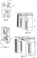
- Figures 9-12 show a further embodiment of the jaws 311, 312, 511, 522 of the input or output pliers 31, 32, 51, and 52.
- the jaws of the plier 31 (in the aforementioned figures it is shown the jaw 311 of the first input plier 31, but the second input plier 32 and the first 51 and the second 52 output pliers are similar) has a gripping plate 3111C, coupled to the respective jaw 311 by means of a pneumatic four-bar linkage 3113.
- the central control unit U coordinates the operation of the machining machine 1, and in particular of the pliers 31, 32, 51, and 52 and of the machining head 41.
Landscapes
- Engineering & Computer Science (AREA)
- Life Sciences & Earth Sciences (AREA)
- Mechanical Engineering (AREA)
- Wood Science & Technology (AREA)
- Forests & Forestry (AREA)
- Laser Beam Processing (AREA)
Abstract
capable of moving said beam (T) on said working plane in said advancement direction (V) and in a direction (Y) perpendicular to said advancement direction (V);
a machining cabin (4), having at least one machining head (41) for machining a bent beam (T); and an exit station (5), comprising a first exit plier (51) capable of moving said beam (T) on said working plane (X, Y) in said direction of advancement (V) and in a direction (Y) perpendicular to said advancement direction (V); in that said input station (3) comprise a second input plier (32), arranged between said first input plier (31) and said machining cabin (4), wherein said second input plier (32) is configured to move said beam (T) on said working plane (X, Y) in said advancement direction (V) and in a direction (Y) perpendicular to said advancement direction (V).
Description
- The present invention concerns a machine for machining pieces, in particular oblong and bent pieces, and related machining method.
- More in detail, the invention concerns a machine of the aforementioned type, designed and created in particular to allow the machining of long and generally heavy wooden pieces, generally beams, using known working means, which present structural advantages that allow both the machining of straight beams and of bent beams.
- In the following, the description will be aimed at the machining of wooden pieces having the prevailing longitudinal dimension, with possible curvature, but it is clear that the same should not be considered limited to this specific use.
- As is well known, in wooden construction it is often necessary to use oblong beams for the construction of roofs and other structural parts.
- In order to satisfy the demand for these worked beams, there are various types of machining centers and machines on the market, which in some cases are composed of a loading system, a central body, and an unloading system. The loading system is in turn composed of a loading buffer, a singularizer, and a roller conveyor.
- The central body is structured as a machining cabin, inside which the necessary tools and the working unit(s) are located. The plier, therefore, not only moves the piece during the machining but holds it in position to ensure precise and stable positioning.
- At the entrance to the machining area and the cabin, the beam encounters three rollers: two lateral and one upper. The lateral rollers are designed to center the beam, while the upper roller exerts downward pressure, ensuring the correct positioning of the piece with respect to the vertical axis.
- Inside the machining cabin, there is a 6-axis working unit, which allows the machining of every part of the beam, including the surface or lower face. Once the machining is completed, the beam is moved towards the unloading system through a further exit roller conveyor. Here, initially, the unloading plier intervenes, positioning the machined piece on the roller conveyor, and then the pusher intervenes to push the piece onto the unloading buffer.
- However, the machining machine according to the prior art has some limitations.
- Recently, the market has shown a growing demand for bent beams, i.e. beams with a rectangular section that have a slight curvature of 35 mm every 8 meters. This particular curvature, which serves to improve structural performance.
- The existing machining centers, according to the prior art, are designed in a rigid manner. Therefore, in the case of continuous machining of bent beams, non-optimal machining could occur or, in the worst case, damage could be caused to the machine itself.
- Currently, the bent beams are mainly machined manually, or through the use of gantry machines with a fixed piece where setup and piece reference times are very long. These operating methods bring with them a series of limitations that make them suboptimal compared to the needs of the current market.
- Firstly, manual working is significantly inefficient from the point of view of production times. The precision and accuracy required in the machining of bent beams lead to prolonged machining times, making the entire production process less responsive to market demands and more expensive in terms of labor.
- In addition to the inefficiency due to the lengthening of machining times, the manual working of bent beams entails a high level of risk for operators. Handling and working beams of significant dimensions, especially when they have a curvature, can expose operators to dangers related to handling, lifting, and grinding the pieces. This can cause injuries, accidents, or damage to the beams themselves.
- In light of the above, it is, therefore, the scope of the present invention to propose a machine for machining wood that allows to work even continuously bent beams, including their lower face, without interruptions and also with better precision and speed (general, both for straight beams and for bent beams).
- Another scope of the invention is to make the solution efficient also in economic terms.
- These and other results are obtained according to the invention with the doubling of the pliers used both in the input loading system and in the output unloading system.
- More in detail, an additional loading plier is introduced, alongside the existing one, so as to be able to manage and move the beams with greater precision and flexibility. This addition allows the continuous positioning of the beam with respect to at least the horizontal axis, transverse to the advancement direction of the piece.
- Similarly, the addition of another plier in the unloading system is proposed. This additional plier, working in conjunction with the existing plier, ensures that the beam is correctly positioned and held throughout the entire unloading process as the beam is machined.
- Each pair of pliers can be misaligned from the other. This means that the pliers can operate independently of each other in terms of position, ensuring greater adaptability to the different machining and positioning needs of the beam. This allows, for example, to manage beams with different degrees of deflection or with particular or even irregular shapes, thus offering a versatile and highly performing solution compared to traditional systems.
- It is, therefore, specific object of the present invention a machine for machining oblong pieces, in particular bent beams, wherein said beam comprises a head end and a tail end, wherein said machining machine comprises: supporting means forming a working plane for moving a beam to be machined in an advancement direction; an input station, comprising a first input plier capable of moving said beam on said working plane in said advancement direction and in a direction perpendicular to said advancement direction; a machining cabin, having at least one machining head for machining a bent beam; and an exit station, comprising a first exit plier capable of moving said beam on said working plane in said direction of advancement and in a direction perpendicular to said advancement direction; characterized in that said input station comprise a second input plier,
arranged between said first input plier and said machining cabin, wherein said second input plier is configured to move said beam on said working plane in said advancement direction and in a direction perpendicular to said advancement direction. - Still according to the invention, said exit station can comprise a second exit plier arranged so that said first output plier is positioned between said machining cabin and said second output plier, wherein said second output plier is configured to move said beam on said working plane in said advancement direction and in a direction perpendicular to said advancement direction.
- Still according to the invention, said first input plier can comprise a pair of jaws for gripping said input beam, and/or in that said second input plier comprises a pair of jaws for gripping said input beam.
- Advantageously according to the invention, said first output plier can comprise a pair of jaws for gripping said output beam, and/or in that said second output plier comprises a pair of jaws for gripping said beam in output.
- Again according to the invention, each jaw of the pliers of said input station and said exit station can comprise at least one gripping plate.
- Still according to the invention, each jaw of the pliers of said input station and said exit station can comprise a dovetail coupling, and in that said machine comprises gripping plates removably coupleable to said dovetail coupling, wherein said gripping plates have different thicknesses depending on whether a straight or bent beam has to be moved.
- Still according to the invention, each jaw of the pliers of said input station and said exit station can comprise a four-bar linkage, capable of assuming an extended position, for gripping straight beams, and a retracted position, for gripping bent beams, and a gripping plate, coupled to said four-bar linkage of said jaw.
- Furthermore, according to the invention, said input station can comprise a photocell, for detecting the head end of said beam.
- Preferably according to the invention, said supporting means can comprise a roller conveyor.
Furthermore, according to the invention, said machining head can comprise one or more single or multi-axis machining heads, in particular with six axis for machining all the faces of said beam. - A further object of the present invention is a of machining oblong pieces, in particular bent beams by means of a machine according to any one of the preceding claims, comprising the following steps:
- A. placing a beam on said support means of said input station;
- B. tighten and position said beam using said first and second input clamps for the machining;
- C. moving said beam in said machining cabin, for the machining of said beam by means of said machining head by means of said first and second input pliers and by said first and second exit pliers, so as to transfer said beam onto said exit station; and
- D. extracting said beam from said machining cabin.
- Again according to the invention, said tightening and positioning step B comprises the following sub-steps:
- B1. position said first and second input pliers on said beam respectively at a predefined distance from said tail end and from said head end of said bent beam;
- B2. tightening the jaws of said first and second input pliers on said bent beam, rotating said beam, so as to align it with said advancement direction; and
- B3. moving said beam along said advancement direction introducing it into said machining cabin.
- Advantageously according to the invention, said step B2 of tightening said jaws of said first and second input pliers can comprise the detection of said head end of said beam by means of detection means, such as a photocell and the like.
- Furthermore, according to the invention, said step B2 of tightening said jaws of said first and second input pliers can comprise a second gripping by means of said first and second plier of said input station in two predefined points or working heights of said beam.
- Preferably according to the invention, said tightening and positioning step B can comprise the tightening of said beam by means of said second input plier at a point located near said first input plier, and, following said movement of said beam, said first exit plier clamps said beam close to said head end when it is in said machining cabin.
- Again according to the invention, said tightening and positioning step B can comprise the following sub-step: B4. moving the jaws of each input plier and/or each output plier independently with respect to the respective plier, in a direction orthogonal to said advancement direction, correcting the position of said beam with respect to its longitudinal axis according to the curvature of said beam itself.
- Still according to the invention, said extracting step D can comprise the following sub-step:
- D1. tightening said beam first by means of said first plier and then using said second plier of said exit station, moving it in the advancement direction, while said beam is released first by said first plier and then by said second plier of said input station; and
- D2. releasing said beam by said first and second pliers of said exit station.
- Advantageously according to the invention, said first and second pliers of said input station and/or first and second pliers of said exit station can rotate and/or translate said beam so as to keep it aligned with said advancement direction.
- Still according to the invention, when said beam is bent, said first and second pliers of said input station and/or first and second pliers said exit station can rotate and/or translate said beam so as to have as reference the alignment of the advancement direction, placing it tangential to the barycentric axis or to the neutral axis of said beam itself.
- Also forming the object of the present invention is a computer program comprising instructions which, when the program is executed by a computer, cause the computer to execute the steps of the method, as defined above.
- A further object of the present invention is a storage means readable by a computer comprising instructions which, when executed by a computer, cause the computer to execute the steps of the method, as defined above.
- The present invention will now be described for illustrative but not limitative purposes, according to its preferred embodiments, with particular reference to the figures of the attached drawings, in which:
-
figure 1 shows a top view of a machine for machining wood, according to the present invention; -
figure 2 shows a bent beam; -
figure 3 shows a jaw of a pliers with manual coupling of the gripping plate; -
figure 4 shows a jaw plate for straight beams; -
figure 5 shows a jaw plate for bent beams; -
figure 6 shows the jaw fromfigure 3 with a straight beam jaw plate installed; -
figure 7 shows the jaw offigure 3 with a bent beam jaw plate installed; -
figure 8 shows a bent beam gripped simultaneously by two pliers; -
figure 9 shows a top view of the jaw with an automatic gripping mechanism, in the gripping position for straight beams; -
figure 10 shows a perspective side view offigure 9 ; -
figure 11 shows a top view of the jaw with the automatic gripping mechanism, in the gripping position for bent beams; -
figure 12 shows a perspective side view offigure 11 ; -
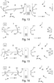
figure 13 shows a schematic view of a machine for machining wood according to the present invention, in which a beam to be machined is loaded; -
figure 14 shows the machine offigure 13 in an operating configuration in which pliers are positioned; -
figure 15 shows the machine offigure 13 in an operating configuration in which the jaws of the pliers are tightened; -
figure 16 shows the machine offigure 13 in an operating configuration in which the position of the head end of a beam to be machined is detected; -
figure 17 shows the machine offigure 13 in an operating configuration in which the beam to be machined is positioned or rotated; -
figure 18 shows the machine offigure 13 in an operating configuration in which the beam to be machined is introduced into a machining cabin; -
figure 19 shows the machine offigure 3 in an operating configuration in which one of the input pliers is repositioned to advance the beam while the latter is being machined; -
figure 20 shows the machine offigure 13 in an operating configuration in which two output pliers grip the beam while it is being machined; -
figure 21 shows the machine offigure 3 in an operating configuration in which the two output pliers extract the beam from the machining cabin and/or continue the machining in progress; -
figure 22 shows the machine offigure 3 in an operating configuration in which the two output pliers release the machined beam; -
figure 23 shows a flow chart of the working method and operation of the machining machine offigure 1 ; and -
figure 24 shows the sub-steps of a step of the method offigure 23 . - In the various figures, similar parts will be indicated with the same numerical references.
- Referring to
figure 1 , we observe amachine 1 for machining beams T, and, in particular, straight or bent beams. - In the following, for convenience, bent beam T will be meant as a wooden beam with a rectangular section having a curvature of 35 mm every 8 meters.
- The use of the
machining machine 1 can be used for machining beams with different degrees of deflection or preload. Referring tofigure 2 , we observe a bent beam T, which presents a deflection represented by the variation δ, and two ends along the longitudinal axis, i.e. a head end Tt and a tail end Tc. - The machine for machining
wood 1 essentially comprises supportingmeans 2, aninput station 3, amachining cabin 4, and anexit station 5. - The supporting means 2 of the machine for machining
wood 1 form a working surface, indicated with the Cartesian references X, Y. The supporting means allow the movement of the beam T both in the advancement direction V, oriented parallel to the axis X, and in a direction Y, perpendicular to said advancement direction V. - The supporting means 2 comprise input loading means 21 and output unloading means 22.
- In a preferred embodiment, the supporting means are constituted by
roller conveyors - In other embodiments, the supporting means can comprise conveyor belts, which allow pieces of different sizes and shapes to be moved. Belts can be made of various materials, such as rubber or plastic.
- In further embodiments, the supporting
means 2 can comprise chain or metal mesh systems, particularly suitable for heavy or large pieces. - In other embodiments, machining centers may provide the conveyor with non-motorized rollers, especially effective if integrated into a production layout that uses other pushing means to move the pieces.
- The
machining machine 1 also comprises aninput station 3, which comprises afirst input plier 31 and asecond input plier 32, both equipped with a pair of jaws, respectively indicated with thenumerical references - The first and
second input pliers respective jaws means 2. Thejaws - The
input pliers input pliers input pliers figure 4 . - Each of said
input plier - The
input station 3 also comprises detection means for detecting the position of the head end Tt of the beam T to be worked, so as to arrange it in an appropriate and programmable way with respect to the advancement direction V. Said detection means comprise, in the present embodiment, aphotocell 33, arranged in correspondence with theentry door 42 of themachining cabin 4. In this way, precise regulation of the entry of the piece into themachining cabin 4 is obtained. - This automated and optical detection system in the case at hand allows greater precision in feeding the piece T into the
machining cabin 4, optimizing working times and reducing margins of error. - The
machining cabin 4, as mentioned, has anentry door 42, arranged in correspondence with theinput station 3, through which the beam can enter through the head end Tt, and anoutput door 43, arranged in correspondence with theexit station 5, through which the beam exits, leaving the machining cabin with the tail end Tc. - Furthermore, the
machining cabin 4 comprises a machining head 41 (see alsofigure 3 ), which in the described embodiment has six axes, so as to machine all six faces of the beam T. In particular, themachining head 4 multi-axis allows performing a wide range of operations, such as milling, drilling, cutting, and other mechanical machining, even using different machining tools (not shown in the figures) and at different angles without the need to reposition the piece, increasing the efficiency of the process. - The
machining head 41 is mobile inside themachining cabin 4. In particular, guides can be provided (not shown in the figures) that allow the movement of themachining head 41 in the three Cartesian axes XYZ. In some embodiments, saidmachining head 41 can be moved by hydraulic or pneumatic members. - The
exit station 5 is arranged downstream of saidmachining cabin 4 and comprises afirst exit plier 51 and asecond exit plier 52, both with pairs of jaws respectively indicated with 511, 512, and 521, 522. Theseexit gripping pliers machining cabin 4 and is transferred to the next step of the production process. Saidpliers - The
exit pliers exit pliers exit pliers figure 21 ). - Each of said
exit pliers - The
pliers input 3 andexit 5 stations can be of various types. In a first embodiment, saidpliers - In one embodiment the pliers may then be pneumatically operated, using compressed air to open and close the jaws. In another embodiment, the pliers can include an electric motor and a ball screw. These pliers are particularly useful for quick operations and can be designed to apply controlled pressure, thus avoiding damage to the wood.
- In other embodiments, suction cup pliers can be provided, which use the vacuum to firmly adhere to the surface of the wooden piece.
- Generally, in any case, the
pliers - Referring to
figure 3 , it can be observed, by way of example, thejaw 311, which has adovetail coupling 3111 for the manual application of agripping plate 3112A, such as the one shown infigure 4 for straight beams T, or of agripping plate 3112B, like the one shown infigure 5 for bent beams T. -
Figures 6 and 7 show thejaw 311 of thefirst input plier 31 with agripping plate 3112A or agripping plate 3112B respectively installed. - Referring to
figure 8 , a bent beam T is shown while it is transported by thefirst input plier 31 and thesecond input plier 32. The grippingplates 3112B are installed on thejaws -
Figures 9-12 show a further embodiment of thejaws output pliers - In particular, in the case in question, the jaws of the plier 31 (in the aforementioned figures it is shown the
jaw 311 of thefirst input plier 31, but thesecond input plier 32 and the first 51 and the second 52 output pliers are similar) has agripping plate 3111C, coupled to therespective jaw 311 by means of a pneumatic four-bar linkage 3113. - In
figures 9 and 10 the four-bar linkage 3113 is in a gripping position for straight beams T (extended), while infigures 11 and 12 said four-bar linkage 3113 is in a gripping position for bent beams T (retracted). - Returning to
figure 1 , and also referring tofigure 13 , themachining machine 1, finally, comprises a central control unit U, which can be integrated into the control logic of a larger machining center or plant in which themachining machine 1 is integrated. This central control unit U is programmable. - The central control unit U coordinates the operation of the
machining machine 1, and in particular of thepliers machining head 41. - More specifically, the central control unit U can be programmed using appropriate programs and can be of different types. For example, in one embodiment, said central control unit U may be a computer numerical control system, to allow precise control of machine tools via a computer.
- In a further embodiment, said central control unit U can be implemented as a PLC (Programmable Logic Controller), generally used to automate the control of mechanical processes.
- In another embodiment, said central control unit U can be a PC-based control system, using a standard or industrial computer as the main control unit, also having the advantage of being able to easily integrate simulation and CAD/ CAM.
- The central control unit U is generally programmed to carry out the different machining steps of the beam T by coordinating the various parts of the
machining machine 1. - The operation of the machine for machining
wood 1 described above takes place as follows. - As mentioned, the
machining machine 1 is controlled by said central control unit U and implements different operating steps of an operating method of saidmachining machine 1 better described below. - With reference to
figure 13 (and to the flow diagrams depicted infigures 23 and24 ), there is the step A, in which the beam T is placed on the supportingmeans 2 present in theinput station 3. Generally, this step may require the use of a handling system such as a robot or similar (not shown in the figure). The beam T is arranged without a precise orientation. Conventionally, the concavity faces the operator. - Referring to
figures 14, 15, 16 ,17, 18, and 19 , themachining machine 1 can be observed in different sub-steps of step B of tightening and positioning. In this tightening and positioning step B, the beam T is tightened and positioned using the first 31 and the second 32 input pliers. - Sub-step B1 involves positioning the pliers at a predefined distance d from the head Tt and tail Tc ends of the beam T, thus ensuring balanced tightening and accurate positioning. In sub-step B2, the jaws of the pliers tighten the beam, rotating it and/or translating it in the directions XY to align it with the advancement direction V. This operation can be assisted by detection means 33 (the photocell), for precise positioning. Following the detection of the position of the head end Tt, the
input pliers figures 15, 16 ,17, 18, and 19 ). - It is observed that in the machining steps, the second working
plier 32 of theinput station 3 and the first workingplier 51 of theexit station 5 can enter themachining cabin 4, respectively through theentry door 42 and theexit door 43. Thefirst input plier 31 and thesecond output plier 52 can also be combined (i.e., placed side by side) with thepliers machining cabin 4. - In sub-step B3, the beam T is moved along the advancement direction V towards the machining
cabin 4. The operating method of themachining machine 1 can include a second gripping step at predefined points or working heights Q1 and Q2, as shown in particular infigure 8 . - Furthermore, in sub-step B4 the
jaws input plier output plier - The operating method of the
machining machine 1, indicated infigure 23 with thenumerical reference 6, also comprises step C of movement in the machining cabin. In themachining cabin 4, the beam T is machined by themachining head 41 while it is held in position by theinput pliers output pliers pliers - The pliers can be configured to rotate the beam T, keeping it aligned with the advancement direction V or, in the case of bent beams, aligning it so that the advancement direction V is tangent to the barycentric axis γ or to the neutral axis v passing through the T beam itself (see also
figure 2 ). In particular, the alignment of the beam T is not binding as some beam machining may require a correction using a corrector on themachining head 41 and not on thepliers - Referring to
figures 20, 21, and 22 , the operation step D of the machining machine is observed, which involves the extraction of the beam T from themachining cabin 4. In particular, in said step D the beam T is initially tightened by both grippingpliers input station 3 and moved in the advancement direction V. Subsequently, it is released first by theinput pliers output pliers - The various operating steps of the
machining machine 1 are, as mentioned, coordinated by the working unit U, which can be programmed using a computer program, to automate the process and guarantee the precision and repeatability of the operations. Programs may include algorithms for precise control ofpliers - An advantage of the present invention is the fact that the machining machine does not necessarily have to include guide rollers like those of the prior art. Said guide rollers can possibly be provided only for the machining of straight beams.
- A further advantage of the present invention is the fact that it is possible to work without distinction on straight or bent beams of any size.
- The present invention has been described for illustrative but not limitative purposes, according to its preferred embodiments, but it is to be understood that modifications and/or changes can be introduced by those skilled in the art without departing from the relevant scope as defined in the enclosed claims.
Claims (17)
- Machine (1) for machining oblong pieces, in particular bent beams (T), wherein said beam (T) comprises a head end (Tt) and a tail end (Tc), wherein said machining machine (1) comprises:supporting means (2) forming a working plane (X, Y) for moving a beam (T) to be machined in an advancement direction (A);an input station (3), comprising a first input plier (31) capable of moving said beam (T) on said working plane in said advancement direction (A) and in a direction (Y) perpendicular to said advancement direction (A);a machining cabin (4), having at least one machining head (41) for machining a bent beam (T); andan exit station (5), comprising a first exit plier (51) capable of moving said beam (T) on said working plane (X, Y) in said direction of advancement (A) and in a direction (Y) perpendicular to said advancement direction (A);characterizedin that said input station (3) comprise a second input plier (32),arranged between said first input plier (31) and said machining cabin (4),wherein said second input plier (32) is configured to move said beam (T) on said working plane (X, Y) in said advancement direction (A) and in a direction (Y) perpendicular to said advancement direction (A).
- Machine (1) according to claim 1, characterized in that said exit station (5) comprises a second exit plier (52)
arranged so that said first output plier (51) is positioned between said machining cabin (4) and said second output plier (52),
wherein said second output plier (52) is configured to move said beam (T) on said working plane (X, Y) in said advancement direction (A) and in a direction (Y) perpendicular to said advancement direction (A). - Machine (1) according to any one of the preceding claims, characterizedin that said first input plier (31) comprises a pair of jaws (311, 312) for gripping said input beam (T), and/orin that said second input plier (32) comprises a pair of jaws (321, 322) for gripping said input beam (T).
- Machine (1) according to any one of the preceding claims, when dependent on claim 2, characterizedin that said first output plier (51) comprises a pair of jaws (511, 522) for gripping said output beam (T), and/orin that said second output plier (52) comprises a pair of jaws (521, 522) for gripping said beam (T) in output.
- Machine (1) according to claims 3 and 4, characterized in that each jaw (311, 312, 511, 522) of the pliers of said input station (3) and said exit station (5) comprises at least one gripping plate (3112A, 3112B, 3112C).
- Machine (1) according to the preceding claim, characterizedin that each jaw (311, 312, 511, 522) of the pliers of said input station (3) and said exit station (5) comprises a dovetail coupling (3111), andin that said machine (1) comprises gripping plates (3112A, 3112B) removably coupleable to said dovetail coupling (3111), wherein said gripping plates (3112A, 3112B) have different thicknesses depending on whether a straight or bent beam (T) has to be moved.
- Machine (1) according to claim 5, characterized in that each jaw (311, 312, 511, 522) of the pliers of said input station (3) and said exit station (5) comprisesa four-bar linkage (3113), capable of assuming an extended position, for gripping straight beams (T), and a retracted position, for gripping bent beams (T), anda gripping plate (3111C), coupled to said four-bar linkage (3113) of said jaw (311).
- Machine (1) according to any one of the preceding claims, characterized in that said input station (3) comprises a photocell (33), for detecting the head end (Tt) of said beam (T).
- Method (6) of machining oblong pieces, in particular bent beams (T) by means of a machine (1) according to any one of the preceding claims, comprising the following steps:A. placing a beam (T) on said support means (2) of said input station (3);B. tighten and position said beam (T) using said first (31) and second (32) input clamps for the machining;C. moving said beam (T) in said machining cabin (4), for the machining of said beam (T) by means of said machining head (41) by means of said first (31) and second (32) input pliers and by said first (51) and second (52) exit pliers, so as to transfer said beam (T) onto said exit station (5); andD. extracting said beam (T) from said machining cabin (4).
- Machining method (6) according to the preceding claim, characterized in that said tightening and positioning step B comprises the following sub-steps:B1. position said first (31) and second (32) input pliers on said beam (T) respectively at a predefined distance (d) from said tail end (Tc) and from said head end (Tt) of said bent beam (T);B2. tightening the jaws of said first (31) and second (32) input pliers on said bent beam (T), rotating said beam (T), so as to align it with said advancement direction (A); andB3. moving said beam (T) along said advancement direction (A) introducing it into said machining cabin (4).
- Machining method (6) according to the preceding claim, characterized in that said step B2 of tightening said jaws of said first (31) and second (32) input pliers comprises the detection of said head end (Tt) of said beam (T) by means of detection means (33), such as a photocell and the like.
- Machining method (6) according to any one of claims 10 or 11, characterized in that said step B2 of tightening said jaws of said first (31) and second (32) input pliers comprises a second gripping by means of said first (31) and second (32) plier of said input station (3) in two predefined points or working heights (Q1, Q2) of said beam (T).
- Machining method (6) according to any one of claims 9-12, characterizedin that said tightening and positioning step B comprises the tightening of said beam (T) by means of said second input plier (32) at a point (Q3) located near said first input plier (31), andin that, following said movement of said beam (T), said first exit plier (51) clamps said beam (T) close to said head end (Tt) when it is in said machining cabin (4).
- Machining method (6) according to the preceding claim, characterized in that said tightening and positioning step B comprises the following sub-step:
B4. moving the jaws (311, 312, 321, 322, 511, 512, 521, 522) of each input plier (31, 32) and/or each output plier (51, 52) independently with respect to the respective plier, in a direction (Y) orthogonal to said advancement direction (A), correcting the position of said beam (T) with respect to its longitudinal axis according to the curvature of said beam (T) itself. - Machining method (6) according to any one of claims 9-14, characterized in that said extracting step D comprises the following sub-step:D1. tightening said beam (T) first by means of said first plier (51) and then using said second plier (52) of said exit station (5), moving it in the advancement direction (A), while said beam (T) is released first by said first plier (31) and then by said second plier (32) of said input station (3); andD2. releasing said beam (T) by said first (51) and second (52) pliers of said exit station (5).
- Machining method (6) according to any one of claims 9-15, characterized in that said first (31) and second (32) pliers of said input station (3) and/or first (51) and second (52) pliers of said exit station (5) rotate and/or translate said beam (T) so as to keep it aligned with said advancement direction (A).
- Machining method according to the preceding claim, characterized in that, when said beam (T) is bent, said first (31) and second (32) pliers of said input station (3) and/or first (51) and second (52) pliers said exit station (5) rotate and/or translate said beam (T) so as to have as reference the alignment of the advancement direction (A), placing it tangential to the barycentric axis (γ) or to the neutral axis (v) of said beam (T) itself.
Applications Claiming Priority (1)
| Application Number | Priority Date | Filing Date | Title |
|---|---|---|---|
| IT102023000028272A IT202300028272A1 (en) | 2023-12-28 | 2023-12-28 | MACHINE FOR PROCESSING PIECES, IN PARTICULAR OBLONGUOUS AND BENDED PIECES, AND RELATED PROCESSING METHOD |
Publications (1)
| Publication Number | Publication Date |
|---|---|
| EP4578614A1 true EP4578614A1 (en) | 2025-07-02 |
Family
ID=90363735
Family Applications (1)
| Application Number | Title | Priority Date | Filing Date |
|---|---|---|---|
| EP24221599.4A Pending EP4578614A1 (en) | 2023-12-28 | 2024-12-19 | Machine for machining pieces, in particular oblong and bent pieces, and related machining method |
Country Status (2)
| Country | Link |
|---|---|
| EP (1) | EP4578614A1 (en) |
| IT (1) | IT202300028272A1 (en) |
Citations (4)
| Publication number | Priority date | Publication date | Assignee | Title |
|---|---|---|---|---|
| DE20002961U1 (en) * | 1999-02-22 | 2000-07-13 | Hundegger, Hans, 87749 Hawangen | Device for feeding a workpiece |
| EP1304188A2 (en) * | 2001-10-19 | 2003-04-23 | IMPRESA 2000 DI SACCHI PARIDE E C. s.a.s. | A method and a machine for machining components made of wood or the like |
| EP3539740A1 (en) * | 2018-03-16 | 2019-09-18 | Algemene Machinebouw De Muynck NV | Improved device for processing a beam |
| DE102018110942A1 (en) * | 2018-05-07 | 2019-11-07 | Homag Plattenaufteiltechnik Gmbh | Workpiece machining system, in particular a panel sizing saw, and method for operating a workpiece machining system and control device |
-
2023
- 2023-12-28 IT IT102023000028272A patent/IT202300028272A1/en unknown
-
2024
- 2024-12-19 EP EP24221599.4A patent/EP4578614A1/en active Pending
Patent Citations (4)
| Publication number | Priority date | Publication date | Assignee | Title |
|---|---|---|---|---|
| DE20002961U1 (en) * | 1999-02-22 | 2000-07-13 | Hundegger, Hans, 87749 Hawangen | Device for feeding a workpiece |
| EP1304188A2 (en) * | 2001-10-19 | 2003-04-23 | IMPRESA 2000 DI SACCHI PARIDE E C. s.a.s. | A method and a machine for machining components made of wood or the like |
| EP3539740A1 (en) * | 2018-03-16 | 2019-09-18 | Algemene Machinebouw De Muynck NV | Improved device for processing a beam |
| DE102018110942A1 (en) * | 2018-05-07 | 2019-11-07 | Homag Plattenaufteiltechnik Gmbh | Workpiece machining system, in particular a panel sizing saw, and method for operating a workpiece machining system and control device |
Also Published As
| Publication number | Publication date |
|---|---|
| IT202300028272A1 (en) | 2025-06-28 |
Similar Documents
| Publication | Publication Date | Title |
|---|---|---|
| CN108527009B (en) | Autonomous production line | |
| CN108326476B (en) | Flexible automatic welding system for tower shoes of communication tower | |
| WO2021237981A1 (en) | Automatic shoemaking production line | |
| CN101312805B (en) | Machine tool | |
| CN108000217B (en) | Robot hub machining center | |
| CN211360662U (en) | But automatic feeding's numerical control lathe | |
| CN110000873A (en) | A kind of wood structures loading and unloading system and method | |
| CN110498244A (en) | Long handle bevel gear finishing automatic assembly line | |
| CN207973211U (en) | A kind of area coordinate type Work transfer apparatus | |
| CN210360513U (en) | An automatic loading and unloading device in a CNC machine tool | |
| CN208051355U (en) | Skylight guide rail automatic punching production line | |
| JPS62255012A (en) | Automatic production systematizing device for gear machining device | |
| CN210550059U (en) | Metal workpiece deburring workstation | |
| CN221248356U (en) | Automatic loading and unloading grinding station and CNC grinder | |
| IT202300028272A1 (en) | MACHINE FOR PROCESSING PIECES, IN PARTICULAR OBLONGUOUS AND BENDED PIECES, AND RELATED PROCESSING METHOD | |
| JPH0592336A (en) | Clamp device for long-size workpiece | |
| CN116586842A (en) | Welding equipment suitable for production of marine pipe of multi-size work piece | |
| CN210745801U (en) | A small battery pack PCB board automatic installation equipment | |
| CN106392190A (en) | Device for machining workpieces, in particular saw blades | |
| CN223670499U (en) | Welding positioning equipment and automobile production line | |
| CN223819746U (en) | Door frame angle sawing device | |
| CN119347375B (en) | Full-automatic connecting rod and safety lock rod mounting machine and working method thereof | |
| CN218874635U (en) | Sleeve mills processing with transport inflatable anchor clamps | |
| CN119566822B (en) | Automatic welding production line and method for guide seats | |
| CN223804445U (en) | Automatic feeding machine |
Legal Events
| Date | Code | Title | Description |
|---|---|---|---|
| PUAI | Public reference made under article 153(3) epc to a published international application that has entered the european phase |
Free format text: ORIGINAL CODE: 0009012 |
|
| STAA | Information on the status of an ep patent application or granted ep patent |
Free format text: STATUS: THE APPLICATION HAS BEEN PUBLISHED |
|
| AK | Designated contracting states |
Kind code of ref document: A1 Designated state(s): AL AT BE BG CH CY CZ DE DK EE ES FI FR GB GR HR HU IE IS IT LI LT LU LV MC ME MK MT NL NO PL PT RO RS SE SI SK SM TR |
|
| STAA | Information on the status of an ep patent application or granted ep patent |
Free format text: STATUS: REQUEST FOR EXAMINATION WAS MADE |
|
| 17P | Request for examination filed |
Effective date: 20251201 |
|
| GRAP | Despatch of communication of intention to grant a patent |
Free format text: ORIGINAL CODE: EPIDOSNIGR1 |
|
| STAA | Information on the status of an ep patent application or granted ep patent |
Free format text: STATUS: GRANT OF PATENT IS INTENDED |
|
| INTG | Intention to grant announced |
Effective date: 20260223 |