EP4578307A2 - Refillable aerosol delivery device and related method - Google Patents
Refillable aerosol delivery device and related method Download PDFInfo
- Publication number
- EP4578307A2 EP4578307A2 EP25168523.6A EP25168523A EP4578307A2 EP 4578307 A2 EP4578307 A2 EP 4578307A2 EP 25168523 A EP25168523 A EP 25168523A EP 4578307 A2 EP4578307 A2 EP 4578307A2
- Authority
- EP
- European Patent Office
- Prior art keywords
- aerosol
- flow director
- aerosol delivery
- pat
- delivery device
- Prior art date
- Legal status (The legal status is an assumption and is not a legal conclusion. Google has not performed a legal analysis and makes no representation as to the accuracy of the status listed.)
- Pending
Links
Images



Classifications
-
- A—HUMAN NECESSITIES
- A24—TOBACCO; CIGARS; CIGARETTES; SIMULATED SMOKING DEVICES; SMOKERS' REQUISITES
- A24F—SMOKERS' REQUISITES; MATCH BOXES; SIMULATED SMOKING DEVICES
- A24F47/00—Smokers' requisites not otherwise provided for
-
- A—HUMAN NECESSITIES
- A24—TOBACCO; CIGARS; CIGARETTES; SIMULATED SMOKING DEVICES; SMOKERS' REQUISITES
- A24B—MANUFACTURE OR PREPARATION OF TOBACCO FOR SMOKING OR CHEWING; TOBACCO; SNUFF
- A24B15/00—Chemical features or treatment of tobacco; Tobacco substitutes, e.g. in liquid form
- A24B15/10—Chemical features of tobacco products or tobacco substitutes
- A24B15/16—Chemical features of tobacco products or tobacco substitutes of tobacco substitutes
- A24B15/167—Chemical features of tobacco products or tobacco substitutes of tobacco substitutes in liquid or vaporisable form, e.g. liquid compositions for electronic cigarettes
-
- A—HUMAN NECESSITIES
- A24—TOBACCO; CIGARS; CIGARETTES; SIMULATED SMOKING DEVICES; SMOKERS' REQUISITES
- A24F—SMOKERS' REQUISITES; MATCH BOXES; SIMULATED SMOKING DEVICES
- A24F40/00—Electrically operated smoking devices; Component parts thereof; Manufacture thereof; Maintenance or testing thereof; Charging means specially adapted therefor
- A24F40/40—Constructional details, e.g. connection of cartridges and battery parts
-
- A—HUMAN NECESSITIES
- A24—TOBACCO; CIGARS; CIGARETTES; SIMULATED SMOKING DEVICES; SMOKERS' REQUISITES
- A24F—SMOKERS' REQUISITES; MATCH BOXES; SIMULATED SMOKING DEVICES
- A24F40/00—Electrically operated smoking devices; Component parts thereof; Manufacture thereof; Maintenance or testing thereof; Charging means specially adapted therefor
- A24F40/40—Constructional details, e.g. connection of cartridges and battery parts
- A24F40/42—Cartridges or containers for inhalable precursors
-
- A—HUMAN NECESSITIES
- A24—TOBACCO; CIGARS; CIGARETTES; SIMULATED SMOKING DEVICES; SMOKERS' REQUISITES
- A24F—SMOKERS' REQUISITES; MATCH BOXES; SIMULATED SMOKING DEVICES
- A24F40/00—Electrically operated smoking devices; Component parts thereof; Manufacture thereof; Maintenance or testing thereof; Charging means specially adapted therefor
- A24F40/40—Constructional details, e.g. connection of cartridges and battery parts
- A24F40/46—Shape or structure of electric heating means
-
- A—HUMAN NECESSITIES
- A24—TOBACCO; CIGARS; CIGARETTES; SIMULATED SMOKING DEVICES; SMOKERS' REQUISITES
- A24F—SMOKERS' REQUISITES; MATCH BOXES; SIMULATED SMOKING DEVICES
- A24F40/00—Electrically operated smoking devices; Component parts thereof; Manufacture thereof; Maintenance or testing thereof; Charging means specially adapted therefor
- A24F40/40—Constructional details, e.g. connection of cartridges and battery parts
- A24F40/48—Fluid transfer means, e.g. pumps
-
- A—HUMAN NECESSITIES
- A24—TOBACCO; CIGARS; CIGARETTES; SIMULATED SMOKING DEVICES; SMOKERS' REQUISITES
- A24F—SMOKERS' REQUISITES; MATCH BOXES; SIMULATED SMOKING DEVICES
- A24F40/00—Electrically operated smoking devices; Component parts thereof; Manufacture thereof; Maintenance or testing thereof; Charging means specially adapted therefor
- A24F40/40—Constructional details, e.g. connection of cartridges and battery parts
- A24F40/48—Fluid transfer means, e.g. pumps
- A24F40/485—Valves; Apertures
-
- A—HUMAN NECESSITIES
- A24—TOBACCO; CIGARS; CIGARETTES; SIMULATED SMOKING DEVICES; SMOKERS' REQUISITES
- A24F—SMOKERS' REQUISITES; MATCH BOXES; SIMULATED SMOKING DEVICES
- A24F40/00—Electrically operated smoking devices; Component parts thereof; Manufacture thereof; Maintenance or testing thereof; Charging means specially adapted therefor
- A24F40/90—Arrangements or methods specially adapted for charging batteries thereof
- A24F40/95—Arrangements or methods specially adapted for charging batteries thereof structurally associated with cases
-
- A—HUMAN NECESSITIES
- A61—MEDICAL OR VETERINARY SCIENCE; HYGIENE
- A61M—DEVICES FOR INTRODUCING MEDIA INTO, OR ONTO, THE BODY; DEVICES FOR TRANSDUCING BODY MEDIA OR FOR TAKING MEDIA FROM THE BODY; DEVICES FOR PRODUCING OR ENDING SLEEP OR STUPOR
- A61M15/00—Inhalators
- A61M15/06—Inhaling appliances shaped like cigars, cigarettes or pipes
-
- A—HUMAN NECESSITIES
- A24—TOBACCO; CIGARS; CIGARETTES; SIMULATED SMOKING DEVICES; SMOKERS' REQUISITES
- A24F—SMOKERS' REQUISITES; MATCH BOXES; SIMULATED SMOKING DEVICES
- A24F15/00—Receptacles or boxes specially adapted for cigars, cigarettes, simulated smoking devices or cigarettes therefor
- A24F15/01—Receptacles or boxes specially adapted for cigars, cigarettes, simulated smoking devices or cigarettes therefor specially adapted for simulated smoking devices or cigarettes therefor
- A24F15/015—Receptacles or boxes specially adapted for cigars, cigarettes, simulated smoking devices or cigarettes therefor specially adapted for simulated smoking devices or cigarettes therefor with means for refilling of liquid inhalable precursors
-
- A—HUMAN NECESSITIES
- A24—TOBACCO; CIGARS; CIGARETTES; SIMULATED SMOKING DEVICES; SMOKERS' REQUISITES
- A24F—SMOKERS' REQUISITES; MATCH BOXES; SIMULATED SMOKING DEVICES
- A24F40/00—Electrically operated smoking devices; Component parts thereof; Manufacture thereof; Maintenance or testing thereof; Charging means specially adapted therefor
- A24F40/10—Devices using liquid inhalable precursors
-
- A—HUMAN NECESSITIES
- A24—TOBACCO; CIGARS; CIGARETTES; SIMULATED SMOKING DEVICES; SMOKERS' REQUISITES
- A24F—SMOKERS' REQUISITES; MATCH BOXES; SIMULATED SMOKING DEVICES
- A24F40/00—Electrically operated smoking devices; Component parts thereof; Manufacture thereof; Maintenance or testing thereof; Charging means specially adapted therefor
- A24F40/40—Constructional details, e.g. connection of cartridges and battery parts
- A24F40/44—Wicks
-
- A—HUMAN NECESSITIES
- A61—MEDICAL OR VETERINARY SCIENCE; HYGIENE
- A61M—DEVICES FOR INTRODUCING MEDIA INTO, OR ONTO, THE BODY; DEVICES FOR TRANSDUCING BODY MEDIA OR FOR TAKING MEDIA FROM THE BODY; DEVICES FOR PRODUCING OR ENDING SLEEP OR STUPOR
- A61M2209/00—Ancillary equipment
- A61M2209/04—Tools for specific apparatus
- A61M2209/045—Tools for specific apparatus for filling, e.g. for filling reservoirs
Definitions
- the present disclosure relates to aerosol delivery devices such as electronic cigarettes, and more particularly to aerosol delivery devices including an atomizer.
- the atomizer may be configured to heat an aerosol precursor composition, which may be made or derived from tobacco or otherwise incorporate tobacco, to form an inhalable substance for human consumption.
- a longitudinal axis of the liquid transport element may extend substantially perpendicularly to a longitudinal axis of the flow director.
- the outer body may be sealed to the base.
- the outer body may engage the base via threaded engagement.
- the aerosol delivery device may additionally include an O-ring compressed between the outer body and the base.
- the aerosol delivery device may further include a mouthpiece.
- the mouthpiece may be sealed to the outer body and the flow director.
- the base may include one or more fill ports configured to receive the aerosol precursor composition therethrough.
- the atomizer may be sealed to the flow director.
- an aerosol delivery device operation method may include retaining an aerosol precursor composition in a reservoir defined between a flow director and an outer body.
- the flow director may extend between a first flow director end and a second flow director end.
- the method may include directing the aerosol precursor composition from the reservoir through a liquid transport element of an atomizer extending through the flow director at a position between the first flow director end and the second flow director end.
- the method may additionally include receiving an electrical current through a heating element of the atomizer.
- the method may further include vaporizing at least a portion of the aerosol precursor composition to produce an aerosol within the flow director.
- the method may further include receiving the aerosol precursor composition through one or more fill ports defined in a base.
- Directing the aerosol precursor composition through the liquid transport element may include directing the aerosol precursor composition through a capillary channel.
- Directing the aerosol precursor composition through the liquid transport element may further include directing the aerosol precursor composition through a porous monolith to the heating element.
- receiving the electrical current through the heating element may include receiving the electrical current through a wire defining a plurality of coils extending around the liquid transport element. Additionally, the method may include directing the aerosol out of the flow director through a mouthpiece. The method may further include retaining the aerosol precursor composition in the reservoir with a seal between the outer body and the base. The method may additionally include retaining the aerosol precursor composition in the reservoir with a seal between the mouthpiece and the outer body and a seal between the mouthpiece and the flow director.
- aerosol as used herein is meant to include vapors, gases and aerosols of a form or type suitable for human inhalation, whether or not visible, and whether or not of a form that might be considered to be smoke-like.
- an aerosol delivery device can comprise two or more shells that are joined and are separable.
- an aerosol delivery device can possess at one end a control body comprising a shell containing one or more reusable components (e.g., a rechargeable battery and various electronics for controlling the operation of that article), and at the other end and removably attached thereto a shell containing a disposable portion (e.g., a disposable flavor-containing cartridge).
- reusable components e.g., a rechargeable battery and various electronics for controlling the operation of that article
- a disposable portion e.g., a disposable flavor-containing cartridge
- the aerosol delivery device may incorporate a battery and/or other electrical power source (e.g., a capacitor) to provide current flow sufficient to provide various functionalities to the aerosol delivery device, such as powering of a heater, powering of control systems, powering of indicators, and the like.
- the power source can take on various embodiments.
- the power source is able to deliver sufficient power to rapidly heat the heating element to provide for aerosol formation and power the aerosol delivery device through use for a desired duration of time.
- the power source preferably is sized to fit conveniently within the aerosol delivery device so that the aerosol delivery device can be easily handled. Additionally, a preferred power source is of a sufficiently light weight to not detract from a desirable smoking experience.
- FIG. 1 illustrates an aerosol delivery device 100 including a control body 200 and a cartridge 300.
- the control body 200 and the cartridge 300 can be permanently or detachably aligned in a functioning relationship.
- Various mechanisms may connect the cartridge 300 to the control body 200 to result in a threaded engagement, a press-fit engagement, an interference fit, a magnetic engagement, or the like.
- the aerosol delivery device 100 may be substantially rod-like, substantially tubular shaped, or substantially cylindrically shaped in some embodiments when the cartridge 300 and the control body 200 are in an assembled configuration.
- various other configurations such as rectangular or fob-shaped may be employed in other embodiments.
- the aerosol delivery devices are generally described herein as resembling the size and shape of a traditional smoking article, in other embodiments differing configurations and larger capacity reservoirs, which may be referred to as "tanks,” may be employed.
- the cartridge 300 and the control body 200 may be referred to as being disposable or as being reusable.
- the control body 200 may have a replaceable battery or a rechargeable battery and/or capacitor and thus may be combined with any type of recharging technology, including connection to a typical alternating current electrical outlet, connection to a car charger (i.e., cigarette lighter receptacle), and connection to a computer, such as through a universal serial bus (USB) cable.
- the cartridge 300 may comprise a single-use cartridge, as disclosed in U.S. Pat. No. 8,910,639 to Chang et al. , which is incorporated herein by reference in its entirety.
- FIG. 2 illustrates an exploded view of the control body 200 of the aerosol delivery device 100 (see, FIG. 1 ) according to an example embodiment of the present disclosure.
- the control body 200 may comprise a coupler 202, an outer body 204, a sealing member 206, an adhesive member 208 (e.g., KAPTON ® tape), a flow sensor 210 (e.g., a puff sensor or pressure switch), a control component 212, a spacer 214, an electrical power source 216 (e.g., a capacitor and/or a battery, which may be rechargeable), a circuit board with an indicator 218 (e.g., a light emitting diode (LED)), a connector circuit 220, and an end cap 222.
- electrical power sources are described in U.S. Pat. No. 9,484,155 to Peckerar et al. , the disclosure of which is incorporated herein by reference in its entirety.
- the indicator 218 may comprise one or more light emitting diodes.
- the indicator 218 can be in communication with the control component 212 through the connector circuit 220 and be illuminated, for example, during a user draw on a cartridge coupled to the coupler 202, as detected by the flow sensor 210.
- the end cap 222 may be adapted to make visible the illumination provided thereunder by the indicator 218. Accordingly, the indicator 218 may be illuminated during use of the aerosol delivery device 100 to simulate the lit end of a smoking article.
- the indicator 218 can be provided in varying numbers and can take on different shapes and can even be an opening in the outer body (such as for release of sound when such indicators are present).
- receptacles in a smoking device that include an identifier that detects a non-uniformity in infrared transmissivity of an inserted component and a controller that executes a detection routine as the component is inserted into the receptacle;
- U.S. Pat. No. 6,040,560 to Fleischhauer et al. describes a defined executable power cycle with multiple differential phases;
- U.S. Pat. No. 5,934,289 to Watkins et al. discloses photonic-optronic components;
- U.S. Pat. No. 5,954,979 to Counts et al. discloses means for altering draw resistance through a smoking device;
- components related to electronic aerosol delivery articles and disclosing materials or components that may be used in the present article include U.S. Pat. No. 4,735,217 to Gerth et al. ; U.S. Pat. No. 5,249,586 to Morgan et al. ; U.S. Pat. No. 5,666,977 to Higgins et al. ; U.S. Pat. No. 6,053,176 to Adams et al. ; U.S. 6,164,287 to White ; U.S. Pat No. 6,196,218 to Voges ; U.S. Pat. No. 6,810,883 to Felter et al. ; U.S. Pat. No.
- heating element 326 various other embodiments of methods may be employed to form the heating element 326, and various other embodiments of heating elements may be employed in the atomizer 310.
- a stamped heating element may be employed in the atomizer, as described in U.S. Pat. No. 9,491,974 to DePiano et al., which is incorporated herein by reference in its entirety.
- additional representative heating elements and materials for use therein are described in U.S. Pat. No. 5,060,671 to Counts et al.; U.S. Pat. No. 5,093,894 to Deevi et al.; U.S. Pat. No. 5,224,498 to Deevi et al.; U.S. Pat. No.
- a variety of heater components may be used in the present aerosol delivery device.
- one or more microheaters or like solid state heaters may be used.
- Microheaters and atomizers incorporating microheaters suitable for use in the presently disclosed devices are described in U.S. Pat. No. 8,881,737 to Collett et al., which is incorporated herein by reference in its entirety.
- a sensor in the aerosol delivery device 100 may sense the puff.
- the control body 200 may direct current to the heating element 326 through a circuit including the first heating terminal 320 and the second heating terminal 321.
- the heating element 326 may vaporize the aerosol precursor composition directed to an aerosolization zone from the reservoir 312 by the liquid transport element 324.
- the mouthpiece 326 may allow passage of air and entrained vapor (i.e., the components of the aerosol precursor composition in an inhalable form) from the cartridge 300 to a consumer drawing thereon.
- an aerosol delivery device can be chosen from components described in the art and commercially available. Reference is made for example to the reservoir and heater system for controllable delivery of multiple aerosolizable materials in an electronic smoking article disclosed in U.S. Pat. App. Pub. No. 2014/0000638 to Sebastian et al., which is incorporated herein by reference in its entirety.
- substantially the entirety of the cartridge may be formed from one or more carbon materials, which may provide advantages in terms of biodegradability and absence of wires.
- the heating element may comprise carbon foam
- the reservoir may comprise carbonized fabric
- graphite may be employed to form an electrical connection with the power source and control component.
- FIGS. 4 and 5 illustrate a cartridge 400 according to an additional example embodiment of the present disclosure.
- FIG. 4 illustrates the cartridge in an exploded configuration.
- FIG. 5 illustrates the cartridge 400 in an assembled configuration.
- the components of the cartridge 400 may be substantially similar to, or the same as, corresponding components described above in relation to FIG. 1 through FIG. 3 .
- the cartridge 400 may include a base 402, a flow director 408, an atomizer 410, an outer body 414, and a mouthpiece 416.
- a first end of the outer body 414 may engage the base 402.
- An opposing second end of the outer body 414 may engage the mouthpiece 416.
- the flow director 408 may extend from a first end 408A at the base 402 through the outer body 414 to a second end 408B at the mouthpiece 416. Thereby, as illustrated in FIG. 5 , a reservoir 412 may be defined between the flow director 408 and the outer body 414.
- the reservoir 412 may define an open space configured to receive an aerosol precursor composition.
- a fibrous substrate may be present in at least a portion of the reservoir 412 to hold aerosol precursor composition similar to the reservoir substrate 312 illustrated in FIG. 3 .
- the atomizer 410 may be configured to vaporize the aerosol precursor composition received from the reservoir 412.
- the atomizer 410 may include a liquid transport element 424 and a heating element 426.
- the heating element 426 may comprise a wire defining a plurality of coils extending around the liquid transport element 424.
- the atomizer 410 may include first and second connectors 428A, 428B contacting the coils at first and second opposing ends of the heating element 426.
- the connectors 428A, 428B may be configured to engage first and second heating terminals 420, 421 (see, FIG. 7 ) in order to supply power thereto.
- the atomizer 410 may extend through the flow director 408. More particularly, a longitudinal axis of the liquid transport element 424 may extend substantially perpendicularly to a longitudinal axis of the flow director 408 such that the atomizer 410 extends across the flow director 408.
- the flow director 408 may include one or more apertures 429A, 429B extending therethrough, transverse to a longitudinal aperture 431 extending through the flow director.
- the atomizer 410 may extend at least partially through each of the apertures 429A, 429B such that the atomizer extends across the longitudinal aperture 431.
- the liquid transport element 424 may include a capillary channel 430 extending therethrough.
- the capillary channel 430 may be configured to receive aerosol precursor composition from the reservoir 412.
- the capillary channel 430 may be in fluid communication with the reservoir 412. Accordingly, the aerosol precursor composition contained in the reservoir 412 may enter the liquid transport element 424 via the capillary channel 430.
- the liquid transport element 424 may comprise a porous monolith.
- the liquid transport element 424 may comprise a porous ceramic material composed of silica and/or alumina as exemplary materials. In some examples, where the liquid transport element 424 comprises a mixture of silica and alumina then a heater may be utilized.
- the heater may be in the form of a conductive mesh, rather than a heater coil, formed from a plurality of crossing, conductive filaments that wrap around the liquid transport element 424 in order to provide a more uniform heat distribution.
- conductive meshes are described in U.S. Pat. Appl. No. 15/472,839 to Davis et al., filed March 29, 2017 , which is incorporated herein by reference in its entirety.
- the cartridge 400 may be coupled to a control body such as the control body 200 of FIG. 2 .
- the control body 200 may verify that the cartridge 400 is genuine and/or perform other functions (e.g., preventing further heating of the heating element 426 after a predetermined number of cumulative seconds of heating have occurred, which may correspond to a substantially empty cartridge) by communicating with an electronic component 406 via an electronic component terminal 404. Thereafter, when the flow sensor 210 (see, FIG. 2 ) of the control body 200 detects a puff on the cartridge 400, the control body 200 may direct current from the electrical power source 216 (see, FIG. 2 ) to the cartridge. The electrical current may thereby be directed through the first and second heating terminals 420, 421 to the first and second connectors 428A, 428B.
- the first and second heating terminals 420, 421 may extend at least partially through the flow director 408.
- the first and second heating terminals 420, 421 may be molded into the flow director 408 (e.g., in-molded in the flow director during the formation thereof) and extend along at least a portion of the length thereof.
- the first and second heating terminals 420, 421 may extend along a portion of a length thereof and terminate at a location at which the atomizer 410 extends across the flow director 408.
- first and second heating terminals 420, 421 may contact the first and second connectors 428A, 428B, respectively, without blocking the apertures 429A, 429B in the flow director 408 through which the atomizer 410 extends.
- the other ends of the first and second heating terminals 420, 421 and the outer end of the electronic component terminal 404 may extend through openings defined in the base 402 such that the ends are exposed and configured for engagement with corresponding electrical contacts of a control body.
- the electrical current may be directed through the heating element 426, in order to produce heat (e.g., via joule heating), or may be conducted directly through the liquid transport element.
- the heat may be transferred to the aerosol precursor composition directed through the liquid transport element 424 such that a vapor is produced inside of the flow director 408.
- the vapor may join with air directed through the flow director 408 and travel to a user via the mouthpiece 416 (see, e.g., FIG. 8 ). More particular, the vapor may be produced by the atomizer 410 within the longitudinal aperture 431 extending through the flow director 408.
- provision of a separate atomization cavity may not be necessary.
- the capacity of the reservoir 412 for a given cartridge size may be relatively larger.
- the longitudinal aperture 431 may define a substantially constant cross-section, perpendicular to the longitudinal length of the flow director 408, at each location along the length of the flow director.
- the base 402 may define a base opening 433 that may match a size and shape of the longitudinal aperture 431 extending through the flow director 408.
- the flow director 408 may extend through the mouthpiece 416 (see, e.g., FIG. 8 ) or mate with an aperture in the mouthpiece having the same size and shape of the longitudinal aperture 431 extending the flow director. Accordingly, a smooth flow path may be defined through the cartridge 400 so as to allow flow therethrough with reduced pressure drop.
- the reservoir 412 may define an open space configured to receive an aerosol precursor composition.
- the reservoir 412 may be sealed such that aerosol precursor composition cannot escape therefrom other than through the atomizer 410 in the manner described herein.
- the atomizer 410 and more particularly, the first and second connectors 428A, 428B, may engage the apertures 429A, 429B defined through the flow director 408 and through which the atomizer extends.
- the first and second connectors 428A, 428B may respectively engage one of the apertures 429A, 429B via press fit.
- the atomizer 410 may be sealed with respect to the flow director 408.
- the outer body 414 may be sealed to the mouthpiece 416 and a first end of the flow director 408 may be sealed to the mouthpiece.
- the mouthpiece 416 may be ultrasonically welded to the outer body 414 and the flow director 408.
- the outer body 414 may be sealed to the base 402.
- the outer body 414 may be ultrasonically welded to the base 402.
- the cartridge 400 may include features configured to facilitate refilling.
- the base 402 may define one or more fill ports 436.
- the open space defined by the reservoir 412 within the outer housing 414 may receive aerosol precursor composition directed through the one or more fill ports 436.
- the one or more fill ports 436 may respectively comprise a one-way valve 438.
- the one-way valves 438 may be configured to allow flow of the aerosol precursor composition through the fill ports 436 into the reservoir 412, and prevent flow outwardly therefrom.
- the one-way valves 438 may comprise diaphragm check valves, which may be formed from silicone or other resilient material and which may be biased to a closed configuration.
- a nozzle or extension of a refilling bottle may engage the filling port(s) 436 and/or the one way valve(s) 438 and direct aerosol precursor composition therethrough to refill the cartridge 400.
- the outer body 414 may be transparent or translucent along at least a portion thereof, such that a user may view the quantity of aerosol precursor composition contained therein, which may be useful to determine the level of aerosol precursor composition in the reservoir 412 during use and refilling of the cartridge 400.
- Example embodiments of one-way valves that may be included in the cartridge 400 and associated refilling bottles and other aerosol precursor composition refilling components are described in U.S. Pat. Appl. No. 15/165,928 to Sebastian et al., filed May 26, 2016 and U.S. Pat. Appl. Pub. No. 2016/0217882 to Davis et al., which are incorporated herein by reference in their entireties. Further, U.S. Pat. Appl. Pub. No. 2017/0013880 to O'Brien et al., discloses an aerosol delivery device including a refillable reservoir and a container for refilling the reservoir, and is incorporated herein by reference in its entirety.
- the refilling bottle may threadingly engage the cartridge, snap into engagement therewith, or otherwise create a secure connection with the cartridge.
- the refilling bottle may then dispense the aerosol precursor composition into the cartridge by pumping or squeezing the refilling bottle, or by allowing pressurized fluid within the refilling bottle to expel the aerosol precursor composition into the cartridge.
- the filling port(s) may be configured to receive aerosol precursor composition from a refilling bottle that is also configured to refill a so-called "tank,” which defines a relatively large reservoir for an aerosol delivery device.
- the filling ports may be sized and configured to receive the nozzle of a tank refilling bottle, or the tank refilling bottle may be provided with a second nozzle configured to engage the filling port of the cartridge. Accordingly, the reservoir of the cartridge may be refilled with embodiments of refilling bottles that may be employed to refill multiple types of aerosol delivery devices.
- the cartridge of the present disclosure may be refilled and reused.
- reuse of the cartridge may provide cost savings and reduce the amount of waste associated with use of the cartridge as compared to single-use disposable cartridges.
- cartridges for aerosol delivery devices have traditionally employed fibrous wicks to transport aerosol precursor composition to a heating element.
- fibrous wicks to transport aerosol precursor composition to a heating element.
- cartridges have not generally been configured to be refillable.
- the cartridge may be refilled and reused repeatedly.
- an aerosol delivery device operation method may include retaining an aerosol precursor composition in a reservoir defined between a flow director and an outer body, the flow director extending between a first flow director end and a second flow director end at operation 502. Further, the method may include directing the aerosol precursor composition from the reservoir through a liquid transport element of an atomizer extending through the flow director at a position between the first flow director end and the second flow director end at operation 504. The method may additionally include receiving an electrical current through a heating element of the atomizer at operation 506. The method may further include vaporizing at least a portion of the aerosol precursor composition to produce an aerosol within the flow director at operation 508.
Landscapes
- Health & Medical Sciences (AREA)
- Engineering & Computer Science (AREA)
- Veterinary Medicine (AREA)
- Chemical & Material Sciences (AREA)
- Anesthesiology (AREA)
- Biomedical Technology (AREA)
- Heart & Thoracic Surgery (AREA)
- Hematology (AREA)
- Life Sciences & Earth Sciences (AREA)
- Animal Behavior & Ethology (AREA)
- General Health & Medical Sciences (AREA)
- Chemical Kinetics & Catalysis (AREA)
- Pulmonology (AREA)
- Bioinformatics & Cheminformatics (AREA)
- Public Health (AREA)
- General Chemical & Material Sciences (AREA)
- Containers And Packaging Bodies Having A Special Means To Remove Contents (AREA)
- Medicinal Preparation (AREA)
- Nozzles (AREA)
- Catching Or Destruction (AREA)
- Disinfection, Sterilisation Or Deodorisation Of Air (AREA)
- Pipe Accessories (AREA)
- Colloid Chemistry (AREA)
- Physical Or Chemical Processes And Apparatus (AREA)
Abstract
Description
- The present disclosure relates to aerosol delivery devices such as electronic cigarettes, and more particularly to aerosol delivery devices including an atomizer. The atomizer may be configured to heat an aerosol precursor composition, which may be made or derived from tobacco or otherwise incorporate tobacco, to form an inhalable substance for human consumption.
- Many devices have been proposed through the years as improvements upon, or alternatives to, smoking products that require combusting tobacco for use. Many of those devices purportedly have been designed to provide the sensations associated with cigarette, cigar, or pipe smoking, but without delivering considerable quantities of incomplete combustion and pyrolysis products that result from the burning of tobacco. To this end, there have been proposed numerous alternative smoking products, flavor generators, and medicinal inhalers that utilize electrical energy to vaporize or heat a volatile material, or attempt to provide the sensations of cigarette, cigar, or pipe smoking without burning tobacco to a significant degree. See, for example, the various alternative smoking articles, aerosol delivery devices and heat generating sources set forth in the background art described in
U.S. Pat. No. 8,881,737 to Collett et al. ,U.S. Pat. App. Pub. No. 2013/0255702 to Griffith Jr. et al. ,U.S. Pat. App. Pub. No. 2014/0000638 to Sebastian et al. ,U.S. Pat. App. Pub. No. 2014/0096781 to Sears et al. ,U.S. Pat. App. Pub. No. 2014/0096782 to Ampolini et al. , andU.S. Pat. App. Pub. No. 2015/0059780 to Davis et al. , which are incorporated herein by reference in their entireties. See also, for example, the various embodiments of products and heating configurations described in the background sections ofU.S. Pat. Nos. 5,388,594 to Counts et al. and8,079,371 to Robinson et al. , which are incorporated by reference in their entireties. - However, it may be desirable to provide aerosol delivery devices with alternate configurations. Such configurations may provide for refilling and reuse of the aerosol delivery device. Thus, advances with respect to aerosol delivery devices may be desirable.
- The present disclosure relates to aerosol delivery devices configured to produce aerosol and which aerosol delivery devices, in some embodiments, may be referred to as electronic cigarettes. In one aspect, an aerosol delivery device is provided. The aerosol delivery device may include an outer body, a base, and a flow director extending from a first flow director end to a second flow director end through the outer body such that a reservoir may be defined between the flow director and the outer body. The reservoir may define an open space configured to receive an aerosol precursor composition. Additionally, the aerosol delivery device may include an atomizer extending through the flow director at a position between the first flow director end and the second flow director end. The atomizer may include a liquid transport element and a heating element configured to vaporize at least a portion of the aerosol precursor composition to produce an aerosol within the flow director.
- In some embodiments the liquid transport element may include a capillary channel extending therethrough. The liquid transport element may include a porous monolith. The heating element may include a wire defining a plurality of coils extending around the liquid transport element. The aerosol delivery device may additionally include first and second connectors contacting the coils at first and second opposing ends of the heating element.
- In some embodiments a longitudinal axis of the liquid transport element may extend substantially perpendicularly to a longitudinal axis of the flow director. The outer body may be sealed to the base. The outer body may engage the base via threaded engagement. The aerosol delivery device may additionally include an O-ring compressed between the outer body and the base. The aerosol delivery device may further include a mouthpiece. The mouthpiece may be sealed to the outer body and the flow director. The base may include one or more fill ports configured to receive the aerosol precursor composition therethrough. The atomizer may be sealed to the flow director.
- In an additional aspect, an aerosol delivery device operation method is provided. The method may include retaining an aerosol precursor composition in a reservoir defined between a flow director and an outer body. The flow director may extend between a first flow director end and a second flow director end. Further, the method may include directing the aerosol precursor composition from the reservoir through a liquid transport element of an atomizer extending through the flow director at a position between the first flow director end and the second flow director end. The method may additionally include receiving an electrical current through a heating element of the atomizer. The method may further include vaporizing at least a portion of the aerosol precursor composition to produce an aerosol within the flow director.
- In some embodiments, the method may further include receiving the aerosol precursor composition through one or more fill ports defined in a base. Directing the aerosol precursor composition through the liquid transport element may include directing the aerosol precursor composition through a capillary channel. Directing the aerosol precursor composition through the liquid transport element may further include directing the aerosol precursor composition through a porous monolith to the heating element.
- In some embodiments receiving the electrical current through the heating element may include receiving the electrical current through a wire defining a plurality of coils extending around the liquid transport element. Additionally, the method may include directing the aerosol out of the flow director through a mouthpiece. The method may further include retaining the aerosol precursor composition in the reservoir with a seal between the outer body and the base. The method may additionally include retaining the aerosol precursor composition in the reservoir with a seal between the mouthpiece and the outer body and a seal between the mouthpiece and the flow director.
- The present disclosure thus includes, without limitation, the following embodiments:
- Embodiment 1: An aerosol delivery device, comprising: an outer body; a base; a flow director extending from a first flow director end to a second flow director end through the outer body such that a reservoir is defined between the flow director and the outer body, the reservoir defining an open space configured to receive an aerosol precursor composition; and an atomizer extending through the flow director at a position between the first flow director end and the second flow director end, the atomizer including a liquid transport element and a heating element configured to vaporize at least a portion of the aerosol precursor composition to produce an aerosol within the flow director.
- Embodiment 2: The aerosol delivery device of any preceding embodiment, or any combination of preceding embodiments, wherein the liquid transport element comprises a capillary channel extending therethrough.
- Embodiment 3: The aerosol delivery device of any preceding embodiment, or any combination of preceding embodiments, wherein the liquid transport element comprises a porous monolith.
- Embodiment 4: The aerosol delivery device of any preceding embodiment, or any combination of preceding embodiments, wherein the heating element comprises a wire defining a plurality of coils extending around the liquid transport element.
- Embodiment 5: The aerosol delivery device of any preceding embodiment, or any combination of preceding embodiments, further comprising first and second connectors contacting the coils at first and second opposing ends of the heating element.
- Embodiment 6: The aerosol delivery device of any preceding embodiment, or any combination of preceding embodiments, wherein a longitudinal axis of the liquid transport element extends substantially perpendicularly to a longitudinal axis of the flow director.
- Embodiment 7: The aerosol delivery device of any preceding embodiment, or any combination of preceding embodiments, wherein the outer body is sealed to the base.
- Embodiment 8: The aerosol delivery device of any preceding embodiment, or any combination of preceding embodiments, wherein the outer body engages the base via threaded engagement.
- Embodiment 9: The aerosol delivery device of any preceding embodiment, or any combination of preceding embodiments, further comprising an O-ring is compressed between the outer body and the base.
- Embodiment 10: The aerosol delivery device of any preceding embodiment, or any combination of preceding embodiments, further comprising a mouthpiece, wherein the mouthpiece is sealed to the outer body and the flow director.
- Embodiment 11: The aerosol delivery device of any preceding embodiment, or any combination of preceding embodiments, wherein the base comprises one or more fill ports configured to receive the aerosol precursor composition therethrough.
- Embodiment 12: The aerosol delivery device of any preceding embodiment, or any combination of preceding embodiments, wherein the atomizer is sealed to the flow director.
- Embodiment 13: An aerosol delivery device operation method, comprising: retaining an aerosol precursor composition in a reservoir defined between a flow director and an outer body, the flow director extending between a first flow director end and a second flow director end; directing the aerosol precursor composition from the reservoir through a liquid transport element of an atomizer extending through the flow director at a position between the first flow director end and the second flow director end; receiving an electrical current through a heating element of the atomizer; and vaporizing at least a portion of the aerosol precursor composition to produce an aerosol within the flow director.
- Embodiment 14: The aerosol delivery device operation method of any preceding embodiment, or any combination of preceding embodiments, further comprising receiving the aerosol precursor composition through one or more fill ports defined in a base.
- Embodiment 15: The aerosol delivery device operation method of any preceding embodiment, or any combination of preceding embodiments, wherein directing the aerosol precursor composition through the liquid transport element comprises directing the aerosol precursor composition through a capillary channel.
- Embodiment 16: The aerosol delivery device operation method of any preceding embodiment, or any combination of preceding embodiments, wherein directing the aerosol precursor composition through the liquid transport element further comprises directing the aerosol precursor composition through a porous monolith to the heating element.
- Embodiment 17: The aerosol delivery device operation method of any preceding embodiment, or any combination of preceding embodiments, wherein receiving the electrical current through the heating element comprises receiving the electrical current through a wire defining a plurality of coils extending around the liquid transport element.
- Embodiment 18: The aerosol delivery device operation method of any preceding embodiment, or any combination of preceding embodiments, further comprising directing the aerosol out of the flow director through a mouthpiece.
- Embodiment 19: The aerosol delivery device operation method of any preceding embodiment, or any combination of preceding embodiments, further comprising retaining the aerosol precursor composition in the reservoir with a seal between the outer body and the base.
- Embodiment 20: The aerosol delivery device operation method of any preceding embodiment, or any combination of preceding embodiments, further comprising retaining the aerosol precursor composition in the reservoir with a seal between the mouthpiece and the outer body and a seal between the mouthpiece and the flow director.
- These and other features, aspects, and advantages of the present disclosure will be apparent from a reading of the following detailed description together with the accompanying drawings, which are briefly described below. The present disclosure includes any combination of two, three, four, or more features or elements set forth in this disclosure or recited in any one or more of the claims, regardless of whether such features or elements are expressly combined or otherwise recited in a specific embodiment description or claim herein. This disclosure is intended to be read holistically such that any separable features or elements of the disclosure, in any of its aspects and embodiments, should be viewed as intended to be combinable, unless the context of the disclosure clearly dictates otherwise.
- Having thus described the disclosure in the foregoing general terms, reference will now be made to the accompanying drawings, which are not necessarily drawn to scale, and wherein:
-
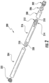
FIG. 1 illustrates a side view of an aerosol delivery device comprising a cartridge and a control body in an assembled configuration according to an example embodiment of the present disclosure; -
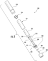
FIG. 2 illustrates the control body ofFIG. 1 in an exploded configuration according to an example embodiment of the present disclosure; -
FIG. 3 illustrates the cartridge ofFIG. 1 in an exploded configuration according to an example embodiment of the present disclosure; -
FIG. 4 illustrates a partially-exploded view of a refillable cartridge according to an example embodiment of the present disclosure; -
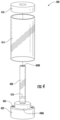
FIG. 5 illustrates the refillable cartridge ofFIG. 4 in an assembled configuration; -
FIG. 6 illustrates an enlarged perspective view of an atomizer of the refillable cartridge ofFIG. 4 ; -
FIG. 7 illustrates a partial longitudinal sectional view through a lower portion of the cartridge ofFIG. 4 ; -
FIG. 8 illustrates a partial longitudinal sectional view through an upper portion of the cartridge ofFIG. 4 ; and -
FIG. 9 schematically illustrates an aerosol delivery device operation method according to an example embodiment of the present disclosure. - The present disclosure will now be described more fully hereinafter with reference to exemplary embodiments thereof. These exemplary embodiments are described so that this disclosure will be thorough and complete, and will fully convey the scope of the disclosure to those skilled in the art. Indeed, the disclosure may be embodied in many different forms and should not be construed as limited to the embodiments set forth herein; rather, these embodiments are provided so that this disclosure will satisfy applicable legal requirements. As used in the specification, and in the appended claims, the singular forms "a", "an", "the", include plural variations unless the context clearly dictates otherwise.
- The present disclosure provides descriptions of aerosol delivery devices. The aerosol delivery devices may use electrical energy to heat a material (preferably without combusting the material to any significant degree) to form an inhalable substance; such articles most preferably being sufficiently compact to be considered "hand-held" devices. An aerosol delivery device may provide some or all of the sensations (e.g., inhalation and exhalation rituals, types of tastes or flavors, organoleptic effects, physical feel, use rituals, visual cues such as those provided by visible aerosol, and the like) of smoking a cigarette, cigar, or pipe, without any substantial degree of combustion of any component of that article or device. The aerosol delivery device may not produce smoke in the sense of the aerosol resulting from by-products of combustion or pyrolysis of tobacco, but rather, that the article or device most preferably yields vapors (including vapors within aerosols that can be considered to be visible aerosols that might be considered to be described as smoke-like) resulting from volatilization or vaporization of certain components of the article or device, although in other embodiments the aerosol may not be visible. In highly preferred embodiments, aerosol delivery devices may incorporate tobacco and/or components derived from tobacco. As such, the aerosol delivery device can be characterized as an electronic smoking article such as an electronic cigarette or "e-cigarette."
- While the systems are generally described herein in terms of embodiments associated with aerosol delivery devices such as so-called "e-cigarettes," it should be understood that the mechanisms, components, features, and methods may be embodied in many different forms and associated with a variety of articles. For example, the description provided herein may be employed in conjunction with embodiments of traditional smoking articles (e.g., cigarettes, cigars, pipes, etc.), heat-not-burn cigarettes, and related packaging for any of the products disclosed herein. Accordingly, it should be understood that the description of the mechanisms, components, features, and methods disclosed herein are discussed in terms of embodiments relating to aerosol delivery devices by way of example only, and may be embodied and used in various other products and methods.
- Aerosol delivery devices of the present disclosure also can be characterized as being vapor-producing articles or medicament delivery articles. Thus, such articles or devices can be adapted so as to provide one or more substances (e.g., flavors and/or pharmaceutical active ingredients) in an inhalable form or state. For example, inhalable substances can be substantially in the form of a vapor (i.e., a substance that is in the gas phase at a temperature lower than its critical point). Alternatively, inhalable substances can be in the form of an aerosol (i.e., a suspension of fine solid particles or liquid droplets in a gas). For purposes of simplicity, the term "aerosol" as used herein is meant to include vapors, gases and aerosols of a form or type suitable for human inhalation, whether or not visible, and whether or not of a form that might be considered to be smoke-like.
- In use, aerosol delivery devices of the present disclosure may be subjected to many of the physical actions employed by an individual in using a traditional type of smoking article (e.g., a cigarette, cigar or pipe that is employed by lighting and inhaling tobacco). For example, the user of an aerosol delivery device of the present disclosure can hold that article much like a traditional type of smoking article, draw on one end of that article for inhalation of aerosol produced by that article, take puffs at selected intervals of time, etc.
- Aerosol delivery devices of the present disclosure generally include a number of components provided within an outer shell or body. The overall design of the outer shell or body can vary, and the format or configuration of the outer body that can define the overall size and shape of the aerosol delivery device can vary. Typically, an elongated body resembling the shape of a cigarette or cigar can be a formed from a single, unitary shell; or the elongated body can be formed of two or more separable pieces. For example, an aerosol delivery device can comprise an elongated shell or body that can be substantially tubular in shape and, as such, resemble the shape of a conventional cigarette or cigar. However, various other shapes and configurations may be employed in other embodiments (e.g., rectangular or fob-shaped).
- In one embodiment, all of the components of the aerosol delivery device are contained within one outer body or shell. Alternatively, an aerosol delivery device can comprise two or more shells that are joined and are separable. For example, an aerosol delivery device can possess at one end a control body comprising a shell containing one or more reusable components (e.g., a rechargeable battery and various electronics for controlling the operation of that article), and at the other end and removably attached thereto a shell containing a disposable portion (e.g., a disposable flavor-containing cartridge). More specific formats, configurations and arrangements of components within the single shell type of unit or within a multi-piece separable shell type of unit will be evident in light of the further disclosure provided herein. Additionally, various aerosol delivery device designs and component arrangements can be appreciated upon consideration of the commercially available electronic aerosol delivery devices.
- Aerosol delivery devices of the present disclosure most preferably comprise some combination of a power source (i.e., an electrical power source), at least one control component (e.g., means for actuating, controlling, regulating and/or ceasing power for heat generation, such as by controlling electrical current flow from the power source to other components of the aerosol delivery device), a heater or heat generation component (e.g., an electrical resistance heating element or component commonly referred to as part of an "atomizer"), and an aerosol precursor composition (e.g., commonly a liquid capable of yielding an aerosol upon application of sufficient heat, such as ingredients commonly referred to as "smoke juice," "e-liquid" and "e-juice"), and a mouthend region or tip for allowing draw upon the aerosol delivery device for aerosol inhalation (e.g., a defined air flow path through the article such that aerosol generated can be withdrawn therefrom upon draw).
- Alignment of the components within the aerosol delivery device of the present disclosure can vary. In specific embodiments, the aerosol precursor composition can be located near an end of the aerosol delivery device which may be configured to be positioned proximal to the mouth of a user so as to maximize aerosol delivery to the user. Other configurations, however, are not excluded. Generally, the heating element can be positioned sufficiently near the aerosol precursor composition so that heat from the heating element can volatilize the aerosol precursor (as well as one or more flavorants, medicaments, or the like that may likewise be provided for delivery to a user) and form an aerosol for delivery to the user. When the heating element heats the aerosol precursor composition, a vapor is formed with subsequently condenses to an aerosol suitable for inhalation by a consumer. It should be noted that the foregoing terms are meant to be interchangeable such that reference to release, releasing, releases, or released includes form or generate, forming or generating, forms or generates, and formed or generated. Specifically, an inhalable substance is released in the form of a vapor or aerosol or mixture thereof, wherein such terms are also interchangeably used herein except where otherwise specified.
- As noted above, the aerosol delivery device may incorporate a battery and/or other electrical power source (e.g., a capacitor) to provide current flow sufficient to provide various functionalities to the aerosol delivery device, such as powering of a heater, powering of control systems, powering of indicators, and the like. The power source can take on various embodiments. Preferably, the power source is able to deliver sufficient power to rapidly heat the heating element to provide for aerosol formation and power the aerosol delivery device through use for a desired duration of time. The power source preferably is sized to fit conveniently within the aerosol delivery device so that the aerosol delivery device can be easily handled. Additionally, a preferred power source is of a sufficiently light weight to not detract from a desirable smoking experience.
- More specific formats, configurations and arrangements of components within the aerosol delivery device of the present disclosure will be evident in light of the further disclosure provided hereinafter. Additionally, the selection of various aerosol delivery device components can be appreciated upon consideration of the commercially available electronic aerosol delivery devices. Further, the arrangement of the components within the aerosol delivery device can also be appreciated upon consideration of the commercially available electronic aerosol delivery devices. Examples of commercially available products, for which the components thereof, methods of operation thereof, materials included therein, and/or other attributes thereof may be included in the devices of the present disclosure as well as manufacturers, designers, and/or assignees of components and related technologies that may be employed in the aerosol delivery device of the present disclosure are described in
U.S. Pat. Appl. Ser. No. 15/222,615, filed July 28, 2016, to Watson et al. - One example embodiment of an
aerosol delivery device 100 is illustrated inFIG. 1 . In particular,FIG. 1 illustrates anaerosol delivery device 100 including acontrol body 200 and acartridge 300. Thecontrol body 200 and thecartridge 300 can be permanently or detachably aligned in a functioning relationship. Various mechanisms may connect thecartridge 300 to thecontrol body 200 to result in a threaded engagement, a press-fit engagement, an interference fit, a magnetic engagement, or the like. Theaerosol delivery device 100 may be substantially rod-like, substantially tubular shaped, or substantially cylindrically shaped in some embodiments when thecartridge 300 and thecontrol body 200 are in an assembled configuration. However, as noted above, various other configurations such as rectangular or fob-shaped may be employed in other embodiments. Further, although the aerosol delivery devices are generally described herein as resembling the size and shape of a traditional smoking article, in other embodiments differing configurations and larger capacity reservoirs, which may be referred to as "tanks," may be employed. - In specific embodiments, one or both of the
cartridge 300 and thecontrol body 200 may be referred to as being disposable or as being reusable. For example, thecontrol body 200 may have a replaceable battery or a rechargeable battery and/or capacitor and thus may be combined with any type of recharging technology, including connection to a typical alternating current electrical outlet, connection to a car charger (i.e., cigarette lighter receptacle), and connection to a computer, such as through a universal serial bus (USB) cable. Further, in some embodiments thecartridge 300 may comprise a single-use cartridge, as disclosed inU.S. Pat. No. 8,910,639 to Chang et al. , which is incorporated herein by reference in its entirety. -
FIG. 2 illustrates an exploded view of thecontrol body 200 of the aerosol delivery device 100 (see,FIG. 1 ) according to an example embodiment of the present disclosure. As illustrated, thecontrol body 200 may comprise acoupler 202, anouter body 204, a sealingmember 206, an adhesive member 208 (e.g., KAPTON® tape), a flow sensor 210 (e.g., a puff sensor or pressure switch), acontrol component 212, aspacer 214, an electrical power source 216 (e.g., a capacitor and/or a battery, which may be rechargeable), a circuit board with an indicator 218 (e.g., a light emitting diode (LED)), aconnector circuit 220, and anend cap 222. Examples of electrical power sources are described inU.S. Pat. No. 9,484,155 to Peckerar et al. - With respect to the
flow sensor 210, representative current regulating components and other current controlling components including various microcontrollers, sensors, and switches for aerosol delivery devices are described inU.S. Pat. No. 4,735,217 to Gerth et al. ,U.S. Pat. Nos. 4,922,901 ,4,947,874 , and4,947,875, all to Brooks et al. ,U.S. Pat. No. 5,372,148 to McCafferty et al. ,U.S. Pat. No. 6,040,560 to Fleischhauer et al. ,U.S. Pat. No. 7,040,314 to Nguyen et al. , andU.S. Pat. No. 8,205,622 to Pan , all of which are incorporated herein by reference in their entireties. Reference also is made to the control schemes described inU.S. Pat. No. 9,423,152 to Ampolini et al. - In one embodiment the
indicator 218 may comprise one or more light emitting diodes. Theindicator 218 can be in communication with thecontrol component 212 through theconnector circuit 220 and be illuminated, for example, during a user draw on a cartridge coupled to thecoupler 202, as detected by theflow sensor 210. Theend cap 222 may be adapted to make visible the illumination provided thereunder by theindicator 218. Accordingly, theindicator 218 may be illuminated during use of theaerosol delivery device 100 to simulate the lit end of a smoking article. However, in other embodiments theindicator 218 can be provided in varying numbers and can take on different shapes and can even be an opening in the outer body (such as for release of sound when such indicators are present). - Still further components can be utilized in the aerosol delivery device of the present disclosure. For example,
U.S. Pat. No. 5,154,192 to Sprinkel et al. discloses indicators for smoking articles;U.S. Pat. No. 5,261,424 to Sprinkel, Jr. discloses piezoelectric sensors that can be associated with the mouth-end of a device to detect user lip activity associated with taking a draw and then trigger heating of a heating device;U.S. Pat. No. 5,372,148 to McCafferty et al. discloses a puff sensor for controlling energy flow into a heating load array in response to pressure drop through a mouthpiece;U.S. Pat. No. 5,967,148 to Harris et al. discloses receptacles in a smoking device that include an identifier that detects a non-uniformity in infrared transmissivity of an inserted component and a controller that executes a detection routine as the component is inserted into the receptacle;U.S. Pat. No. 6,040,560 to Fleischhauer et al. describes a defined executable power cycle with multiple differential phases;U.S. Pat. No. 5,934,289 to Watkins et al. discloses photonic-optronic components;U.S. Pat. No. 5,954,979 to Counts et al. discloses means for altering draw resistance through a smoking device;U.S. Pat. No. 6,803,545 to Blake et al. discloses specific battery configurations for use in smoking devices;U.S. Pat. No. 7,293,565 to Griffen et al. discloses various charging systems for use with smoking devices;U.S. Pat. No. 8,402,976 to Fernando et al. discloses computer interfacing means for smoking devices to facilitate charging and allow computer control of the device;U.S. Pat. No. 8,689,804 to Fernando et al. discloses identification systems for smoking devices; andWO 2010/003480 by Flick discloses a fluid flow sensing system indicative of a puff in an aerosol generating system; all of the foregoing disclosures being incorporated herein by reference in their entireties. Further examples of components related to electronic aerosol delivery articles and disclosing materials or components that may be used in the present article includeU.S. Pat. No. 4,735,217 to Gerth et al. ;U.S. Pat. No. 5,249,586 to Morgan et al. ;U.S. Pat. No. 5,666,977 to Higgins et al. ;U.S. Pat. No. 6,053,176 to Adams et al. ;U.S. 6,164,287 to White ;U.S. Pat No. 6,196,218 to Voges ;U.S. Pat. No. 6,810,883 to Felter et al. ;U.S. Pat. No. 6,854,461 to Nichols ;U.S. Pat. No. 7,832,410 to Hon ;U.S. Pat. No. 7,513,253 to Kobayashi ;U.S. Pat. No. 7,896,006 to Hamano ;U.S. Pat. No. 6,772,756 to Shayan ;U.S. Pat. No. 8,156,944 and8,375,957 to Hon ;U.S. Pat. No. 8,528,569 to Newton ;U.S. Pat. No. 8,707,965 to Newton ;U.S. Pat. No. 8,794,231 to Thorens et al. ;U.S. Pat. No. 8,851,083 to Oglesby et al. ;U.S. Pat. No. 8,915,254 and8,925,555 to Monsees et al. ; andU.S. Pat. No. 9,220,302 to DePiano et al. U.S. Pat. App. Pub. Nos. 2006/0196518 and2009/0188490 to Hon ;U.S. Pat. App. Pub. No. 2010/0024834 to Oglesby et al. ;U.S. Pat. App. Pub. No. 2010/0307518 to Wang ;WO 2010/091593 to Hon ; andWO 2013/089551 to Foo , each of which is incorporated herein by reference in its entirety. A variety of the materials disclosed by the foregoing documents may be incorporated into the present devices in various embodiments, and all of the foregoing disclosures are incorporated herein by reference in their entireties. -
FIG. 3 illustrates thecartridge 300 of the aerosol delivery device 100 (see,FIG. 1 ) in an exploded configuration. As illustrated, thecartridge 300 may comprise a base 302, acontrol component terminal 304, anelectronic component 306, aflow director 308, anatomizer 310, a reservoir 312 (e.g., a reservoir substrate), anouter body 314, amouthpiece 316, alabel 318, and first andsecond heating terminals - In some embodiments the first and
second heating terminals flow director 308. For example, the first andsecond heating terminals flow director 308. Accordingly, theflow director 308 and the first and second heating terminals are collectively referred to herein as aflow director assembly 322. Additional description with respect to the first andsecond heating terminals flow director 308 is provided inU.S. Pat. Pub. No. 2015/0335071 to Brinkley et al., which is incorporated herein by reference in its entirety. - The
atomizer 310 may comprise aliquid transport element 324 and aheating element 326. The cartridge may additionally include a base shipping plug engaged with the base and/or a mouthpiece shipping plug engaged with the mouthpiece in order to protect the base and the mouthpiece and prevent entry of contaminants therein prior to use as disclosed, for example, inU.S. Pat. No. 9,220,302 to Depiano - The base 302 may be coupled to a first end of the
outer body 314 and themouthpiece 316 may be coupled to an opposing second end of the outer body to substantially or fully enclose other components of thecartridge 300 therein. For example, thecontrol component terminal 304, theelectronic component 306, theflow director 308, theatomizer 310, and thereservoir 312 may be substantially or entirely retained within theouter body 314. Thelabel 318 may at least partially surround theouter body 314, and optionally thebase 302, and include information such as a product identifier thereon. The base 302 may be configured to engage thecoupler 202 of the control body 200 (see, e.g.,FIG. 2 ). In some embodiments thebase 302 may comprise anti-rotation features that substantially prevent relative rotation between the cartridge and the control body as disclosed inU.S. Pat. App. Pub. No. 2014/0261495 to Novak et al. , which is incorporated herein by reference in its entirety. - The
reservoir 312 may be configured to hold an aerosol precursor composition. Representative types of aerosol precursor components and formulations are also set forth and characterized inU.S. Pat. Nos. 7,726,320 to Robinson et al. ,8,881,737 to Collett et al. , and9,254,002 to Chong et al. U.S. Pat. Pub. Nos. 2013/0008457 to Zheng et al. ;2015/0020823 to Lipowicz et al. ; and2015/0020830 to Koller , as well asWO 2014/182736 to Bowen et al , the disclosures of which are incorporated herein by reference. Other aerosol precursors that may be employed include the aerosol precursors that have been incorporated in the VUSE® product by R. J. Reynolds Vapor Company, the BLU product by Lorillard Technologies, the MISTIC MENTHOL product by Mistic Ecigs, and the VYPE product by CN Creative Ltd. Also desirable are the so-called "smoke juices" for electronic cigarettes that have been available from Johnson Creek Enterprises LLC. Embodiments of effervescent materials can be used with the aerosol precursor, and are described, by way of example, inU.S. Pat. App. Pub. No. 2012/0055494 to Hunt et al. , which is incorporated herein by reference. Further, the use of effervescent materials is described, for example, inU.S. Pat. No. 4,639,368 to Niazi et al. ;U.S. Pat. No. 5,178,878 to Wehling et al. ;U.S. Pat. No. 5,223,264 to Wehling et al. ;U.S. Pat. No. 6,974,590 to Pather et al. ;U.S. Pat. No. 7,381,667 to Bergquist et al. ;U.S. Pat. No. 8,424,541 to Crawford et al ;U.S. Pat. No. 8,627,828 to Strickland et al. ; andU.S. Pat. No. 9,307,787 to Sun et al. U.S. Pat. App. Pub. No. 2010/0018539 to Brinkley et al. andPCT WO 97/06786 to Johnson et al. U.S. Pat. Appl. Ser. Nos. 15/216,582 and15/216,590, each filed July 21, 2016 and each to Davis et al. - The
reservoir 312 may comprise a plurality of layers of nonwoven fibers formed into the shape of a tube encircling the interior of theouter body 314 of thecartridge 300. Thus, liquid components, for example, can be sorptively retained by thereservoir 312. Thereservoir 312 is in fluid connection with theliquid transport element 324. Thus, theliquid transport element 324 may be configured to transport liquid from thereservoir 312 to theheating element 326 via capillary action or other liquid transport mechanism. - As illustrated, the
liquid transport element 324 may be in direct contact with theheating element 326. As further illustrated inFIG. 3 , theheating element 326 may comprise a wire defining a plurality of coils wound about theliquid transport element 324. In some embodiments theheating element 326 may be formed by winding the wire about theliquid transport element 324 as described inU.S. Pat. No. 9,210,738 to Ward U.S. Pat. No. 9,277,770 to DePiano heating element 326. Example materials from which the wire coil may be formed include Kanthal (FeCrAl), Nichrome, Molybdenum disilicide (MoSi2), molybdenum silicide (MoSi), Molybdenum disilicide doped with Aluminum (Mo(Si,Al)2), graphite and graphite-based materials; and ceramic (e.g., a positive or negative temperature coefficient ceramic). - However, various other embodiments of methods may be employed to form the
heating element 326, and various other embodiments of heating elements may be employed in theatomizer 310. For example, a stamped heating element may be employed in the atomizer, as described inU.S. Pat. No. 9,491,974 to DePiano U.S. Pat. No. 5,060,671 to Counts et al.;U.S. Pat. No. 5,093,894 to Deevi et al.;U.S. Pat. No. 5,224,498 to Deevi et al.;U.S. Pat. No. 5,228,460 to Sprinkel Jr. , et al.;U.S. Pat. No. 5,322,075 to Deevi et al.;U.S. Pat. No. 5,353,813 to Deevi et al.;U.S. Pat. No. 5,468,936 to Deevi et al.;U.S. Pat. No. 5,498,850 to Das ;U.S. Pat. No. 5,659,656 to Das ;U.S. Pat. No. 5,498,855 to Deevi et al.;U.S. Pat. No. 5,530,225 to Hajaligol ;U.S. Pat. No. 5,665,262 to Hajaligol ;U.S. Pat. No. 5,573,692 to Das et al.; andU.S. Pat. No. 5,591,368 to Fleischhauer et al., the disclosures of which are incorporated herein by reference in their entireties. Further, chemical heating may be employed in other embodiments. Various additional examples of heaters and materials employed to form heaters are described inU.S. Pat. No. 8,881,737 to Collett et al., which is incorporated herein by reference, as noted above. - A variety of heater components may be used in the present aerosol delivery device. In various embodiments, one or more microheaters or like solid state heaters may be used. Microheaters and atomizers incorporating microheaters suitable for use in the presently disclosed devices are described in
U.S. Pat. No. 8,881,737 to Collett et al., which is incorporated herein by reference in its entirety. - The
first heating terminal 320 and the second heating terminal 321 (e.g., negative and positive heating terminals) are configured to engage opposing ends of theheating element 326 and to form an electrical connection with the control body 200 (see, e.g.,FIG. 2 ) when thecartridge 300 is connected thereto. Further, when thecontrol body 200 is coupled to thecartridge 300, theelectronic component 306 may form an electrical connection with the control body through thecontrol component terminal 304. Thecontrol body 200 may thus employ the electronic component 212 (see,FIG. 2 ) to determine whether thecartridge 300 is genuine and/or perform other functions. Further, various examples of electronic control components and functions performed thereby are described inU.S. Pat. App. Pub. No. 2014/0096781 to Sears et al., which is incorporated herein by reference in its entirety. - During use, a user may draw on the
mouthpiece 316 of thecartridge 300 of the aerosol delivery device 100 (see,FIG. 1 ). This may pull air through an opening in the control body 200 (see, e.g.,FIG. 2 ) or in thecartridge 300. For example, in one embodiment an opening may be defined between thecoupler 202 and theouter body 204 of the control body 200 (see, e.g.,FIG. 2 ), as described inU.S. Pat. No. 9,220,302 aerosol delivery device 100 in other embodiments. As noted above, in some embodiments thecartridge 300 may include theflow director 308. Theflow director 308 may be configured to direct the flow of air received from thecontrol body 200 to theheating element 326 of theatomizer 310. - A sensor in the aerosol delivery device 100 (e.g., the
flow sensor 210 in thecontrol body 200; see,FIG. 2 ) may sense the puff. When the puff is sensed, thecontrol body 200 may direct current to theheating element 326 through a circuit including thefirst heating terminal 320 and thesecond heating terminal 321. Accordingly, theheating element 326 may vaporize the aerosol precursor composition directed to an aerosolization zone from thereservoir 312 by theliquid transport element 324. Thus, themouthpiece 326 may allow passage of air and entrained vapor (i.e., the components of the aerosol precursor composition in an inhalable form) from thecartridge 300 to a consumer drawing thereon. - Various other details with respect to the components that may be included in the
cartridge 300 are provided, for example, inU.S. Pat. App. Pub. No. 2014/0261495 to DePiano et al., which is incorporated herein by reference in its entirety. Additional components that may be included in thecartridge 300 and details relating thereto are provided, for example, inU.S. Pat. Pub. No. 2015/0335071 to Brinkley et al., which is incorporated herein by reference in its entirety. - Various components of an aerosol delivery device according to the present disclosure can be chosen from components described in the art and commercially available. Reference is made for example to the reservoir and heater system for controllable delivery of multiple aerosolizable materials in an electronic smoking article disclosed in
U.S. Pat. App. Pub. No. 2014/0000638 to Sebastian et al., which is incorporated herein by reference in its entirety. - In another embodiment substantially the entirety of the cartridge may be formed from one or more carbon materials, which may provide advantages in terms of biodegradability and absence of wires. In this regard, the heating element may comprise carbon foam, the reservoir may comprise carbonized fabric, and graphite may be employed to form an electrical connection with the power source and control component. An example embodiment of a carbon-based cartridge is provided in
U.S. Pat. App. Pub. No. 2013/0255702 to Griffith et al., which is incorporated herein by reference in its entirety. - However, in some embodiments it may be desirable to provide aerosol delivery devices with alternative configurations. In this regard,
FIGS. 4 and5 illustrate acartridge 400 according to an additional example embodiment of the present disclosure.FIG. 4 illustrates the cartridge in an exploded configuration.FIG. 5 illustrates thecartridge 400 in an assembled configuration. Where not otherwise described and/or illustrated, the components of thecartridge 400 may be substantially similar to, or the same as, corresponding components described above in relation toFIG. 1 through FIG. 3 . - As illustrated, the
cartridge 400 may include abase 402, aflow director 408, anatomizer 410, anouter body 414, and amouthpiece 416. A first end of theouter body 414 may engage thebase 402. An opposing second end of theouter body 414 may engage themouthpiece 416. - The
flow director 408 may extend from afirst end 408A at the base 402 through theouter body 414 to asecond end 408B at themouthpiece 416. Thereby, as illustrated inFIG. 5 , areservoir 412 may be defined between theflow director 408 and theouter body 414. Thereservoir 412 may define an open space configured to receive an aerosol precursor composition. In one or more embodiments, a fibrous substrate may be present in at least a portion of thereservoir 412 to hold aerosol precursor composition similar to thereservoir substrate 312 illustrated inFIG. 3 . - The
atomizer 410 may be configured to vaporize the aerosol precursor composition received from thereservoir 412. In this regard, as illustrated inFIG. 6 , theatomizer 410 may include aliquid transport element 424 and aheating element 426. Theheating element 426 may comprise a wire defining a plurality of coils extending around theliquid transport element 424. Further, theatomizer 410 may include first andsecond connectors heating element 426. Theconnectors second heating terminals 420, 421 (see,FIG. 7 ) in order to supply power thereto. - The
atomizer 410 may extend through theflow director 408. More particularly, a longitudinal axis of theliquid transport element 424 may extend substantially perpendicularly to a longitudinal axis of theflow director 408 such that theatomizer 410 extends across theflow director 408. In this regard, as illustrated inFIG. 7 , theflow director 408 may include one ormore apertures longitudinal aperture 431 extending through the flow director. Theatomizer 410 may extend at least partially through each of theapertures longitudinal aperture 431. - The
liquid transport element 424 may include acapillary channel 430 extending therethrough. Thecapillary channel 430 may be configured to receive aerosol precursor composition from thereservoir 412. In this regard, as illustrated inFIG. 7 , thecapillary channel 430 may be in fluid communication with thereservoir 412. Accordingly, the aerosol precursor composition contained in thereservoir 412 may enter theliquid transport element 424 via thecapillary channel 430. Further, theliquid transport element 424 may comprise a porous monolith. For example, theliquid transport element 424 may comprise a porous ceramic material composed of silica and/or alumina as exemplary materials. In some examples, where theliquid transport element 424 comprises a mixture of silica and alumina then a heater may be utilized. In some instances, the heater may be in the form of a conductive mesh, rather than a heater coil, formed from a plurality of crossing, conductive filaments that wrap around theliquid transport element 424 in order to provide a more uniform heat distribution. Example embodiments of conductive meshes are described inU.S. Pat. Appl. No. 15/472,839 to Davis et al., filed March 29, 2017 - Alternatively, the porous liquid transport element may also be comprised of an electrically conducted ceramic (e.g., boron-doped silicon) that may act as a semiconductor for which resistance is controllable. As such, the liquid transport element may act as the heating element, thereby forgoing the necessity of a heating coil with a plurality of coils and desirably extending a lifetime of the atomizer. Accordingly, the aerosol precursor composition may be wicked from the
capillary channel 430 generally radially outwardly such that theliquid transport element 424 is saturated and such that the aerosol precursor composition reaches theheating element 426. - The
cartridge 400 may be coupled to a control body such as thecontrol body 200 ofFIG. 2 . Thecontrol body 200 may verify that thecartridge 400 is genuine and/or perform other functions (e.g., preventing further heating of theheating element 426 after a predetermined number of cumulative seconds of heating have occurred, which may correspond to a substantially empty cartridge) by communicating with anelectronic component 406 via anelectronic component terminal 404. Thereafter, when the flow sensor 210 (see,FIG. 2 ) of thecontrol body 200 detects a puff on thecartridge 400, thecontrol body 200 may direct current from the electrical power source 216 (see,FIG. 2 ) to the cartridge. The electrical current may thereby be directed through the first andsecond heating terminals second connectors - In some embodiments, as illustrated, the first and
second heating terminals flow director 408. For example, the first andsecond heating terminals second heating terminals atomizer 410 extends across theflow director 408. Thereby, the first andsecond heating terminals second connectors apertures flow director 408 through which theatomizer 410 extends. The other ends of the first andsecond heating terminals electronic component terminal 404 may extend through openings defined in the base 402 such that the ends are exposed and configured for engagement with corresponding electrical contacts of a control body. - Accordingly, the electrical current may be directed through the
heating element 426, in order to produce heat (e.g., via joule heating), or may be conducted directly through the liquid transport element. The heat may be transferred to the aerosol precursor composition directed through theliquid transport element 424 such that a vapor is produced inside of theflow director 408. The vapor may join with air directed through theflow director 408 and travel to a user via the mouthpiece 416 (see, e.g.,FIG. 8 ). More particular, the vapor may be produced by theatomizer 410 within thelongitudinal aperture 431 extending through theflow director 408. Thereby, by configuring theatomizer 410 such that it extends through theflow director 408, provision of a separate atomization cavity may not be necessary. In other words, by producing the vapor within theflow director 408, it may not be necessary to include a separate atomization cavity upstream or downstream of the flow director. Accordingly, the capacity of thereservoir 412 for a given cartridge size may be relatively larger. - In some embodiments the
longitudinal aperture 431 may define a substantially constant cross-section, perpendicular to the longitudinal length of theflow director 408, at each location along the length of the flow director. Further, thebase 402 may define abase opening 433 that may match a size and shape of thelongitudinal aperture 431 extending through theflow director 408. Additionally, theflow director 408 may extend through the mouthpiece 416 (see, e.g.,FIG. 8 ) or mate with an aperture in the mouthpiece having the same size and shape of thelongitudinal aperture 431 extending the flow director. Accordingly, a smooth flow path may be defined through thecartridge 400 so as to allow flow therethrough with reduced pressure drop. - As noted above, the
reservoir 412 may define an open space configured to receive an aerosol precursor composition. Thereservoir 412 may be sealed such that aerosol precursor composition cannot escape therefrom other than through theatomizer 410 in the manner described herein. In this regard, theatomizer 410, and more particularly, the first andsecond connectors apertures flow director 408 and through which the atomizer extends. For example, the first andsecond connectors apertures atomizer 410 may be sealed with respect to theflow director 408. - Further, the
outer body 414 may be sealed to themouthpiece 416 and a first end of theflow director 408 may be sealed to the mouthpiece. For example, themouthpiece 416 may be ultrasonically welded to theouter body 414 and theflow director 408. Additionally, theouter body 414 may be sealed to thebase 402. For example, in some embodiments theouter body 414 may be ultrasonically welded to thebase 402. - However, in other embodiments it may be desirable to provide alternative mechanisms for sealing the
reservoir 412. For example, it may be desirable to configure thecartridge 400 such that theatomizer 410 is removable. However, theatomizer 410 may be irremovably engaged with theflow director 408. Further, theflow director 408 may be irremovably engaged with the base 402 (e.g., ultrasonically welded, adhesively attached, or otherwise substantially permanently connected thereto). As such, replacement of theatomizer 410 may involve replacement of an assembly including the atomizer, theflow director 408, the first andsecond heating terminals electronic component terminal 404, and thebase 402. - Accordingly, these components may be configured to be removable from a remainder of the
cartridge 400. For example, as illustrated inFIG. 7 , thebase 402 may include a plurality ofthreads 402A configured to engage a plurality ofthreads 414A of theouter body 414 such that the outer body engages the base via threaded engagement. Although thethreads cartridge 400 may further comprise a sealing member configured to seal theouter body 414 to thebase 402. For example, an O-ring 432, which may comprise silicone or other resilient material, may extend around thebase 402 and may be compressed between theouter body 414 and the base as the base is threaded into engagement with the outer body. - Further, the
flow director 408 may releasably engage themouthpiece 416. For example, as illustrated inFIG. 8 , theflow director 408 may include a plurality ofthreads 408A configured to engage a plurality ofthreads 416A of themouthpiece 416 such that the flow director engages the mouthpiece via threaded engagement. Although thethreads cartridge 400 may further comprise a sealing member configured to seal theflow director 408 to themouthpiece 416. For example, an O-ring 434, which may comprise silicone or other resilient material, may extend around theflow director 408 and may be compressed between the flow director and the mouthpiece as the flow director is threaded into engagement with the mouthpiece. - As may be understood, the
flow director 408 may threadingly engage the mouthpiece 416 (see,FIG. 8 ) simultaneously with the base 402 threadingly engaging the outer body 414 (see,FIG. 7 ). Further, a pitch of thethreads 408A of theflow director 408 and thethreads 416A of themouthpiece 416 may be equal to a pitch of thethreads 402A of thebase 402 and thethreads 414A of theouter body 414 to allow simultaneous engagement of the flow director and the mouthpiece and the base and the outer body without one set of threads binding before the other, thereby allowing the threads to form a seal by themselves and/or compressing the O-rings - Accordingly, by employing the
threads cartridge 400 may be configured such that an assembly including theatomizer 410 may be removed and replaced. In this regard, the assembly including theatomizer 410 may be replaced when the useful life of the atomizer is complete, or the assembly may be replaced with a differing assembly including a differing atomizer that may, for example, be configured to produce a greater or lesser amount of aerosol with each puff. - As noted above, in some embodiments an assembly including the
atomizer 410 may be replaceable such that a new atomizer may be provided when the atomizer reaches the end of its useable life. In this regard, in some embodiments thecartridge 400 may be refillable such that thecartridge 400 may be repeatedly reused. - Thus, the
cartridge 400 may include features configured to facilitate refilling. For example, as illustrated inFIG. 7 , thebase 402 may define one ormore fill ports 436. Thus, the open space defined by thereservoir 412 within theouter housing 414 may receive aerosol precursor composition directed through the one ormore fill ports 436. Further, the one ormore fill ports 436 may respectively comprise a one-way valve 438. The one-way valves 438 may be configured to allow flow of the aerosol precursor composition through thefill ports 436 into thereservoir 412, and prevent flow outwardly therefrom. For example, the one-way valves 438 may comprise diaphragm check valves, which may be formed from silicone or other resilient material and which may be biased to a closed configuration. Accordingly, a nozzle or extension of a refilling bottle may engage the filling port(s) 436 and/or the one way valve(s) 438 and direct aerosol precursor composition therethrough to refill thecartridge 400. In some embodiments theouter body 414 may be transparent or translucent along at least a portion thereof, such that a user may view the quantity of aerosol precursor composition contained therein, which may be useful to determine the level of aerosol precursor composition in thereservoir 412 during use and refilling of thecartridge 400. - Example embodiments of one-way valves that may be included in the
cartridge 400 and associated refilling bottles and other aerosol precursor composition refilling components are described inU.S. Pat. Appl. No. 15/165,928 to Sebastian et al., filed May 26, 2016 U.S. Pat. Appl. Pub. No. 2016/0217882 to Davis et al., which are incorporated herein by reference in their entireties. Further,U.S. Pat. Appl. Pub. No. 2017/0013880 to O'Brien et al., discloses an aerosol delivery device including a refillable reservoir and a container for refilling the reservoir, and is incorporated herein by reference in its entirety. - In some embodiments the refilling bottle may threadingly engage the cartridge, snap into engagement therewith, or otherwise create a secure connection with the cartridge. The refilling bottle may then dispense the aerosol precursor composition into the cartridge by pumping or squeezing the refilling bottle, or by allowing pressurized fluid within the refilling bottle to expel the aerosol precursor composition into the cartridge. In some embodiments the filling port(s) may be configured to receive aerosol precursor composition from a refilling bottle that is also configured to refill a so-called "tank," which defines a relatively large reservoir for an aerosol delivery device. For example, the filling ports may be sized and configured to receive the nozzle of a tank refilling bottle, or the tank refilling bottle may be provided with a second nozzle configured to engage the filling port of the cartridge. Accordingly, the reservoir of the cartridge may be refilled with embodiments of refilling bottles that may be employed to refill multiple types of aerosol delivery devices.
- Thus, the cartridge of the present disclosure may be refilled and reused. As may be understood, reuse of the cartridge may provide cost savings and reduce the amount of waste associated with use of the cartridge as compared to single-use disposable cartridges. As noted above, cartridges for aerosol delivery devices have traditionally employed fibrous wicks to transport aerosol precursor composition to a heating element. In view of the relatively short lifespan of suck wicks, cartridges have not generally been configured to be refillable. However, by employing a porous monolith as the liquid transport element, and/or by configuring the atomizer such that it is replaceable, and/or utilizing the liquid transport element itself as the heater, as described herein, the cartridge may be refilled and reused repeatedly.
- In an additional embodiment an aerosol delivery device operation method is provided. As illustrated in
FIG. 9 , the method may include retaining an aerosol precursor composition in a reservoir defined between a flow director and an outer body, the flow director extending between a first flow director end and a second flow director end atoperation 502. Further, the method may include directing the aerosol precursor composition from the reservoir through a liquid transport element of an atomizer extending through the flow director at a position between the first flow director end and the second flow director end atoperation 504. The method may additionally include receiving an electrical current through a heating element of the atomizer atoperation 506. The method may further include vaporizing at least a portion of the aerosol precursor composition to produce an aerosol within the flow director atoperation 508. - In some embodiments the method may further include receiving the aerosol precursor composition through one or more fill ports defined in a base. Directing the aerosol precursor composition through the liquid transport element at
operation 504 may include directing the aerosol precursor composition through a capillary channel. Directing the aerosol precursor composition through the liquid transport element atoperation 504 may further include directing the aerosol precursor composition through a porous monolith to the heating element. - In some embodiments receiving the electrical current through the heating element at
operation 506 may include receiving the electrical current through a wire defining a plurality of coils extending around the liquid transport element. The method may further include directing the aerosol out of the flow director through a mouthpiece. Additionally, the method may include retaining the aerosol precursor composition in the reservoir with a seal between the outer body and the base. Further, the method may include retaining the aerosol precursor composition in the reservoir with a seal between the mouthpiece and the outer body and a seal between the mouthpiece and the flow director. - Many modifications and other embodiments of the disclosure will come to mind to one skilled in the art to which this disclosure pertains having the benefit of the teachings presented in the foregoing descriptions and the associated drawings. Therefore, it is to be understood that the disclosure is not to be limited to the specific embodiments disclosed herein and that modifications and other embodiments are intended to be included within the scope of the appended claims. Although specific terms are employed herein, they are used in a generic and descriptive sense only and not for purposes of limitation.
Claims (12)
- An atomizer comprising:
a liquid transport element comprising a rigid monolith, the rigid monolith having a first side and a second side opposite to the first side, and the rigid monolith including at least one aperture passing from the first side to the second side for providing a conduit for vaporized aerosol precursor; anda heating element,wherein the heating element extends at least partially across the at least one aperture. - The atomizer of claim 1, wherein the at least one aperture comprises a centrally located aperture.
- The atomizer of claim 1, wherein the heating element comprises at least one heating element selected from the group comprising a heating element wire and a conductive mesh.
- The atomizer of claim 1, further comprising at least one member arranged toward the first side of the rigid monolith and sandwiching the heater element therebetween .
- The atomizer of claim 1, further comprising electrical leads.
- The atomizer of claim 1, wherein the rigid monolith comprises silica.
- An aerosol delivery device comprising:an outer body; andan atomizer comprising:a liquid transport element comprising a rigid monolith, the rigid monolith having a first side and a second side opposite to the first side, and the rigid monolith including at least one aperture passing from the first side to the second side for providing a conduit for vaporized aerosol precursor; anda heating element,wherein the heating element extends at least partially across the at least one aperture.
- The device of claim 7, wherein the at least one aperture comprises a centrally located aperture.
- The device of claim 7, wherein the heating element comprises at least one heating element selected from the group comprising a heating element wire and a conductive mesh.
- The device of claim 1, further comprising at least one member arranged toward the first side of the rigid monolith and sandwiching the heater element therebetween .
- The device of claim 7, further comprising electrical leads.
- The device of claim 7, wherein the rigid monolith comprises silica.
Applications Claiming Priority (3)
| Application Number | Priority Date | Filing Date | Title |
|---|---|---|---|
| US15/493,919 US10314340B2 (en) | 2017-04-21 | 2017-04-21 | Refillable aerosol delivery device and related method |
| EP18721471.3A EP3612045B1 (en) | 2017-04-21 | 2018-04-10 | Refillable aerosol delivery device and related method |
| PCT/IB2018/052525 WO2018193339A1 (en) | 2017-04-21 | 2018-04-10 | Refillable aerosol delivery device and related method |
Related Parent Applications (1)
| Application Number | Title | Priority Date | Filing Date |
|---|---|---|---|
| EP18721471.3A Division EP3612045B1 (en) | 2017-04-21 | 2018-04-10 | Refillable aerosol delivery device and related method |
Publications (2)
| Publication Number | Publication Date |
|---|---|
| EP4578307A2 true EP4578307A2 (en) | 2025-07-02 |
| EP4578307A3 EP4578307A3 (en) | 2026-01-14 |
Family
ID=62092185
Family Applications (2)
| Application Number | Title | Priority Date | Filing Date |
|---|---|---|---|
| EP25168523.6A Pending EP4578307A3 (en) | 2017-04-21 | 2018-04-10 | Refillable aerosol delivery device and related method |
| EP18721471.3A Active EP3612045B1 (en) | 2017-04-21 | 2018-04-10 | Refillable aerosol delivery device and related method |
Family Applications After (1)
| Application Number | Title | Priority Date | Filing Date |
|---|---|---|---|
| EP18721471.3A Active EP3612045B1 (en) | 2017-04-21 | 2018-04-10 | Refillable aerosol delivery device and related method |
Country Status (8)
| Country | Link |
|---|---|
| US (4) | US10314340B2 (en) |
| EP (2) | EP4578307A3 (en) |
| JP (2) | JP7326158B2 (en) |
| KR (2) | KR102598624B1 (en) |
| CN (2) | CN110785092B (en) |
| PL (1) | PL3612045T3 (en) |
| RU (1) | RU2765819C2 (en) |
| WO (1) | WO2018193339A1 (en) |
Families Citing this family (24)
| Publication number | Priority date | Publication date | Assignee | Title |
|---|---|---|---|---|
| US10492530B2 (en) * | 2016-11-15 | 2019-12-03 | Rai Strategic Holdings, Inc. | Two-wire authentication system for an aerosol delivery device |
| WO2018111843A1 (en) * | 2016-12-12 | 2018-06-21 | Vmr Products Llc | Vaporizer cartridge |
| US10314340B2 (en) * | 2017-04-21 | 2019-06-11 | Rai Strategic Holdings, Inc. | Refillable aerosol delivery device and related method |
| PL4094794T3 (en) | 2018-07-23 | 2026-05-04 | Juul Labs, Inc. | Airflow management for vaporizer device |
| JP7630432B2 (en) | 2018-10-08 | 2025-02-17 | ジュール・ラブズ・インコーポレイテッド | Heating elements |
| US12256784B2 (en) | 2018-10-17 | 2025-03-25 | Juul Labs, Inc. | Cartridge for a vaporizer device |
| CA3118735A1 (en) | 2018-11-05 | 2020-05-14 | Juul Labs, Inc. | Cartridges for vaporizer devices |
| GB201818270D0 (en) | 2018-11-09 | 2018-12-26 | Nicoventures Trading Ltd | Component for a vapour provision system |
| US11156766B2 (en) | 2018-11-19 | 2021-10-26 | Rai Strategic Holdings, Inc. | Aerosol delivery device |
| CN209376699U (en) * | 2018-11-30 | 2019-09-13 | 深圳市合元科技有限公司 | Electronic cigarette |
| US12232527B2 (en) * | 2021-05-31 | 2025-02-25 | Shenzhen First Union Technology Co., Ltd. | Electronic cigarette and nozzle assembly |
| EP3914114B1 (en) * | 2019-01-21 | 2024-03-13 | G.D Societa' Per Azioni | Machine and method for the production of a cartridge for an electronic cigarette |
| CN113631056B (en) | 2019-03-29 | 2025-01-07 | 尤尔实验室有限公司 | Cartridges for evaporator devices |
| GB201906279D0 (en) * | 2019-05-03 | 2019-06-19 | Nicoventures Trading Ltd | Electronic aerosol provision system |
| EP3738453B1 (en) * | 2019-05-13 | 2022-03-30 | Tuanfang Liu | Electronic cigarette |
| JP7357770B2 (en) * | 2019-09-06 | 2023-10-06 | フィリップ・モーリス・プロダクツ・ソシエテ・アノニム | Aerosol generator with gap between articles |
| CN211832820U (en) * | 2019-12-02 | 2020-11-03 | 深圳麦克韦尔科技有限公司 | Electronic atomization device and heating assembly and heating structure thereof |
| US12279647B2 (en) | 2019-12-23 | 2025-04-22 | Pax Labs, Inc. | Vaporizer cartridge |
| WO2021163950A1 (en) * | 2020-02-20 | 2021-08-26 | 深圳麦克韦尔科技有限公司 | Heating assembly, atomizer, and electronic cigarette |
| CN111772240B (en) * | 2020-06-15 | 2024-12-17 | 深圳麦克韦尔科技有限公司 | Atomizer and liquid storage assembly and electronic atomizing device thereof |
| KR102468652B1 (en) * | 2020-07-03 | 2022-11-22 | 몬스 주식회사 | Disposable electronic cigarette |
| EP4255232B1 (en) * | 2020-12-03 | 2025-04-16 | Philip Morris Products S.A. | Cartridge of a stick-shaped aerosol-generating article for use with an inductively heating aerosol-generating device |
| USD1028336S1 (en) | 2021-06-22 | 2024-05-21 | Pax Labs, Inc. | Vaporizer cartridge |
| WO2024033848A1 (en) * | 2022-08-10 | 2024-02-15 | AMP Innovations Inc. | Vaporizer cartridge |
Citations (88)
| Publication number | Priority date | Publication date | Assignee | Title |
|---|---|---|---|---|
| US4639368A (en) | 1984-08-23 | 1987-01-27 | Farmacon Research Corporation | Chewing gum containing a medicament and taste maskers |
| US4735217A (en) | 1986-08-21 | 1988-04-05 | The Procter & Gamble Company | Dosing device to provide vaporized medicament to the lungs as a fine aerosol |
| US4922901A (en) | 1988-09-08 | 1990-05-08 | R. J. Reynolds Tobacco Company | Drug delivery articles utilizing electrical energy |
| US4947874A (en) | 1988-09-08 | 1990-08-14 | R. J. Reynolds Tobacco Company | Smoking articles utilizing electrical energy |
| US4947875A (en) | 1988-09-08 | 1990-08-14 | R. J. Reynolds Tobacco Company | Flavor delivery articles utilizing electrical energy |
| US5060671A (en) | 1989-12-01 | 1991-10-29 | Philip Morris Incorporated | Flavor generating article |
| US5093894A (en) | 1989-12-01 | 1992-03-03 | Philip Morris Incorporated | Electrically-powered linear heating element |
| US5154192A (en) | 1989-07-18 | 1992-10-13 | Philip Morris Incorporated | Thermal indicators for smoking articles and the method of application of the thermal indicators to the smoking article |
| US5178878A (en) | 1989-10-02 | 1993-01-12 | Cima Labs, Inc. | Effervescent dosage form with microparticles |
| US5223264A (en) | 1989-10-02 | 1993-06-29 | Cima Labs, Inc. | Pediatric effervescent dosage form |
| US5224498A (en) | 1989-12-01 | 1993-07-06 | Philip Morris Incorporated | Electrically-powered heating element |
| US5228460A (en) | 1991-12-12 | 1993-07-20 | Philip Morris Incorporated | Low mass radial array heater for electrical smoking article |
| US5249586A (en) | 1991-03-11 | 1993-10-05 | Philip Morris Incorporated | Electrical smoking |
| US5261424A (en) | 1991-05-31 | 1993-11-16 | Philip Morris Incorporated | Control device for flavor-generating article |
| US5322075A (en) | 1992-09-10 | 1994-06-21 | Philip Morris Incorporated | Heater for an electric flavor-generating article |
| US5353813A (en) | 1992-08-19 | 1994-10-11 | Philip Morris Incorporated | Reinforced carbon heater with discrete heating zones |
| US5372148A (en) | 1993-02-24 | 1994-12-13 | Philip Morris Incorporated | Method and apparatus for controlling the supply of energy to a heating load in a smoking article |
| US5388594A (en) | 1991-03-11 | 1995-02-14 | Philip Morris Incorporated | Electrical smoking system for delivering flavors and method for making same |
| US5468936A (en) | 1993-03-23 | 1995-11-21 | Philip Morris Incorporated | Heater having a multiple-layer ceramic substrate and method of fabrication |
| US5498850A (en) | 1992-09-11 | 1996-03-12 | Philip Morris Incorporated | Semiconductor electrical heater and method for making same |
| US5498855A (en) | 1992-09-11 | 1996-03-12 | Philip Morris Incorporated | Electrically powered ceramic composite heater |
| US5530225A (en) | 1991-03-11 | 1996-06-25 | Philip Morris Incorporated | Interdigitated cylindrical heater for use in an electrical smoking article |
| US5573692A (en) | 1991-03-11 | 1996-11-12 | Philip Morris Incorporated | Platinum heater for electrical smoking article having ohmic contact |
| US5591368A (en) | 1991-03-11 | 1997-01-07 | Philip Morris Incorporated | Heater for use in an electrical smoking system |
| WO1997006786A1 (en) | 1995-08-18 | 1997-02-27 | R.P. Scherer Limited | Oral fast-dissolving compositions for dopamine agonists |
| US5665262A (en) | 1991-03-11 | 1997-09-09 | Philip Morris Incorporated | Tubular heater for use in an electrical smoking article |
| US5666977A (en) | 1993-06-10 | 1997-09-16 | Philip Morris Incorporated | Electrical smoking article using liquid tobacco flavor medium delivery system |
| US5934289A (en) | 1996-10-22 | 1999-08-10 | Philip Morris Incorporated | Electronic smoking system |
| US5954979A (en) | 1997-10-16 | 1999-09-21 | Philip Morris Incorporated | Heater fixture of an electrical smoking system |
| US5967148A (en) | 1997-10-16 | 1999-10-19 | Philip Morris Incorporated | Lighter actuation system |
| US6040560A (en) | 1996-10-22 | 2000-03-21 | Philip Morris Incorporated | Power controller and method of operating an electrical smoking system |
| US6053176A (en) | 1999-02-23 | 2000-04-25 | Philip Morris Incorporated | Heater and method for efficiently generating an aerosol from an indexing substrate |
| US6164287A (en) | 1998-06-10 | 2000-12-26 | R. J. Reynolds Tobacco Company | Smoking method |
| US6196218B1 (en) | 1999-02-24 | 2001-03-06 | Ponwell Enterprises Ltd | Piezo inhaler |
| US6772756B2 (en) | 2002-02-09 | 2004-08-10 | Advanced Inhalation Revolutions Inc. | Method and system for vaporization of a substance |
| US6803545B2 (en) | 2002-06-05 | 2004-10-12 | Philip Morris Incorporated | Electrically heated smoking system and methods for supplying electrical power from a lithium ion power source |
| US6810883B2 (en) | 2002-11-08 | 2004-11-02 | Philip Morris Usa Inc. | Electrically heated cigarette smoking system with internal manifolding for puff detection |
| US6854461B2 (en) | 2002-05-10 | 2005-02-15 | Philip Morris Usa Inc. | Aerosol generator for drug formulation and methods of generating aerosol |
| US6974590B2 (en) | 1998-03-27 | 2005-12-13 | Cima Labs Inc. | Sublingual buccal effervescent |
| US7040314B2 (en) | 2002-09-06 | 2006-05-09 | Philip Morris Usa Inc. | Aerosol generating devices and methods for generating aerosols suitable for forming propellant-free aerosols |
| US20060196518A1 (en) | 2003-04-29 | 2006-09-07 | Lik Hon | Flameless electronic atomizing cigarette |
| US7293565B2 (en) | 2003-06-30 | 2007-11-13 | Philip Morris Usa Inc. | Electrically heated cigarette smoking system |
| US7381667B2 (en) | 2002-12-27 | 2008-06-03 | Unilever Home & Personal Care Usa, Division Of Conopco, Inc. | Hydroentangled textile and use in a personal cleansing implement |
| US7513253B2 (en) | 2004-08-02 | 2009-04-07 | Canon Kabushiki Kaisha | Liquid medication cartridge and inhaler using the cartridge |
| US20090188490A1 (en) | 2006-11-10 | 2009-07-30 | Li Han | Aerosolizing Inhalation Device |
| WO2010003480A1 (en) | 2008-07-08 | 2010-01-14 | Philip Morris Products S.A. | A flow sensor system |
| US20100018539A1 (en) | 2008-07-28 | 2010-01-28 | Paul Andrew Brinkley | Smokeless tobacco products and processes |
| US20100024834A1 (en) | 2006-09-05 | 2010-02-04 | Oglesby & Butler Research & Development Limited | Container comprising vaporisable matter for use in a vaporising device for vaporising a vaporisable constituent thereof |
| US7726320B2 (en) | 2006-10-18 | 2010-06-01 | R. J. Reynolds Tobacco Company | Tobacco-containing smoking article |
| WO2010091593A1 (en) | 2009-02-11 | 2010-08-19 | Hon Lik | Improved atomizing electronic cigarette |
| US7832410B2 (en) | 2004-04-14 | 2010-11-16 | Best Partners Worldwide Limited | Electronic atomization cigarette |
| US20100307518A1 (en) | 2007-05-11 | 2010-12-09 | Smokefree Innotec Corporation | Smoking device, charging means and method of using it |
| US7896006B2 (en) | 2006-07-25 | 2011-03-01 | Canon Kabushiki Kaisha | Medicine inhaler and medicine ejection method |
| US20120055494A1 (en) | 2010-09-07 | 2012-03-08 | Rj Reynolds Tobacco Company | Smokeless Tobacco Product Comprising Effervescent Composition |
| US8156944B2 (en) | 2006-05-16 | 2012-04-17 | Ruyan Investments (Holdings) Limited | Aerosol electronic cigarette |
| US8205622B2 (en) | 2009-03-24 | 2012-06-26 | Guocheng Pan | Electronic cigarette |
| US20130008457A1 (en) | 2011-07-04 | 2013-01-10 | Junxiang Zheng | Kind of preparation method of e-cigarette liquid |
| US8402976B2 (en) | 2008-04-17 | 2013-03-26 | Philip Morris Usa Inc. | Electrically heated smoking system |
| US8424541B2 (en) | 2007-07-16 | 2013-04-23 | Philip Morris Usa Inc. | Tobacco-free oral flavor delivery pouch product |
| WO2013089551A1 (en) | 2011-12-15 | 2013-06-20 | Foo Kit Seng | An electronic vaporisation cigarette |
| US8528569B1 (en) | 2011-06-28 | 2013-09-10 | Kyle D. Newton | Electronic cigarette with liquid reservoir |
| US20130255702A1 (en) | 2012-03-28 | 2013-10-03 | R.J. Reynolds Tobacco Company | Smoking article incorporating a conductive substrate |
| US20140000638A1 (en) | 2012-06-28 | 2014-01-02 | R.J. Reynolds Tobacco Company | Reservoir and heater system for controllable delivery of multiple aerosolizable materials in an electronic smoking article |
| US8627828B2 (en) | 2003-11-07 | 2014-01-14 | U.S. Smokeless Tobacco Company Llc | Tobacco compositions |
| US8689804B2 (en) | 2008-12-24 | 2014-04-08 | Philip Morris Usa Inc. | Article including identification information for use in an electrically heated smoking system |
| US20140096781A1 (en) | 2012-10-08 | 2014-04-10 | R. J. Reynolds Tobacco Company | Electronic smoking article and associated method |
| US20140096782A1 (en) | 2012-10-08 | 2014-04-10 | R.J. Reynolds Tobacco Company | Electronic smoking article and associated method |
| US8794231B2 (en) | 2008-04-30 | 2014-08-05 | Philip Morris Usa Inc. | Electrically heated smoking system having a liquid storage portion |
| US20140261495A1 (en) | 2013-03-15 | 2014-09-18 | R.J. Reynolds Tobacco Company | Cartridge and control body of an aerosol delivery device including anti-rotation mechanism and related method |
| US8851083B2 (en) | 2005-02-02 | 2014-10-07 | Oglesby & Butler Research & Development Limited | Device for vaporising vaporisable matter |
| US8881737B2 (en) | 2012-09-04 | 2014-11-11 | R.J. Reynolds Tobacco Company | Electronic smoking article comprising one or more microheaters |
| WO2014182736A1 (en) | 2013-05-06 | 2014-11-13 | Ploom, Inc. | Nicotine salt formulations for aerosol devices and methods thereof |
| US8910639B2 (en) | 2012-09-05 | 2014-12-16 | R. J. Reynolds Tobacco Company | Single-use connector and cartridge for a smoking article and related method |
| US8915254B2 (en) | 2005-07-19 | 2014-12-23 | Ploom, Inc. | Method and system for vaporization of a substance |
| US20150020830A1 (en) | 2013-07-22 | 2015-01-22 | Altria Client Services Inc. | Electronic smoking article |
| US20150020823A1 (en) | 2013-07-19 | 2015-01-22 | Altria Client Services Inc. | Liquid aerosol formulation of an electronic smoking article |
| US20150059780A1 (en) | 2013-08-28 | 2015-03-05 | R.J. Reynolds Tobacco Company | Carbon conductive substrate for electronic smoking article |
| US20150335071A1 (en) | 2014-05-23 | 2015-11-26 | R.J. Reynolds Tobacco Company | Sealed Cartridge for an Aerosol Delivery Device and Related Assembly Method |
| US9210738B2 (en) | 2012-12-07 | 2015-12-08 | R.J. Reynolds Tobacco Company | Apparatus and method for winding a substantially continuous heating element about a substantially continuous wick |
| US9220302B2 (en) | 2013-03-15 | 2015-12-29 | R.J. Reynolds Tobacco Company | Cartridge for an aerosol delivery device and method for assembling a cartridge for a smoking article |
| US9254002B2 (en) | 2009-08-17 | 2016-02-09 | Chong Corporation | Tobacco solution for vaporized inhalation |
| US9277770B2 (en) | 2013-03-14 | 2016-03-08 | R. J. Reynolds Tobacco Company | Atomizer for an aerosol delivery device formed from a continuously extending wire and related input, cartridge, and method |
| US9307787B2 (en) | 2008-12-19 | 2016-04-12 | U.S. Smokeless Tobacco Company Llc | Tobacco granules and method of producing tobacco granules |
| US20160217882A1 (en) | 2005-02-25 | 2016-07-28 | Borealis Technology Oy | Scorch-retarding polymer composition |
| US9423152B2 (en) | 2013-03-15 | 2016-08-23 | R. J. Reynolds Tobacco Company | Heating control arrangement for an electronic smoking article and associated system and method |
| US9484155B2 (en) | 2008-07-18 | 2016-11-01 | University Of Maryland | Thin flexible rechargeable electrochemical energy cell and method of fabrication |
| US9491974B2 (en) | 2013-03-15 | 2016-11-15 | Rai Strategic Holdings, Inc. | Heating elements formed from a sheet of a material and inputs and methods for the production of atomizers |
| US20170013880A1 (en) | 2015-07-17 | 2017-01-19 | R. J. Reynolds Tobacco Company | Contained liquid system for refilling aerosol delivery devices |
Family Cites Families (166)
| Publication number | Priority date | Publication date | Assignee | Title |
|---|---|---|---|---|
| US2057353A (en) | 1936-10-13 | Vaporizing unit fob therapeutic | ||
| US1388017A (en) | 1919-09-29 | 1921-08-16 | Nat Mfg Co | Latching means for flexible gates |
| US1514682A (en) | 1923-05-03 | 1924-11-11 | Wilson Harold | Electric vaporizer |
| US1771366A (en) | 1926-10-30 | 1930-07-22 | R W Cramer & Company Inc | Medicating apparatus |
| US1853910A (en) | 1926-12-03 | 1932-04-12 | Studebaker Corp | Brake operating mechanism |
| US2104266A (en) | 1935-09-23 | 1938-01-04 | William J Mccormick | Means for the production and inhalation of tobacco fumes |
| US2483410A (en) | 1945-10-30 | 1949-10-04 | Standard Telephones Cables Ltd | Wide band probe |
| US3200819A (en) | 1963-04-17 | 1965-08-17 | Herbert A Gilbert | Smokeless non-tobacco cigarette |
| US3479561A (en) | 1967-09-25 | 1969-11-18 | John L Janning | Breath operated device |
| US4284089A (en) | 1978-10-02 | 1981-08-18 | Ray Jon P | Simulated smoking device |
| US4303083A (en) | 1980-10-10 | 1981-12-01 | Burruss Jr Robert P | Device for evaporation and inhalation of volatile compounds and medications |
| SE8405479D0 (en) | 1984-11-01 | 1984-11-01 | Nilsson Sven Erik | WANT TO ADMINISTER VOCABULARY, PHYSIOLOGY, ACTIVE SUBJECTS AND DEVICE FOR THIS |
| GB8713645D0 (en) | 1987-06-11 | 1987-07-15 | Imp Tobacco Ltd | Smoking device |
| US5019122A (en) | 1987-08-21 | 1991-05-28 | R. J. Reynolds Tobacco Company | Smoking article with an enclosed heat conductive capsule containing an aerosol forming substance |
| US4986286A (en) | 1989-05-02 | 1991-01-22 | R. J. Reynolds Tobacco Company | Tobacco treatment process |
| US4945931A (en) | 1989-07-14 | 1990-08-07 | Brown & Williamson Tobacco Corporation | Simulated smoking device |
| US5408574A (en) | 1989-12-01 | 1995-04-18 | Philip Morris Incorporated | Flat ceramic heater having discrete heating zones |
| US5144962A (en) | 1989-12-01 | 1992-09-08 | Philip Morris Incorporated | Flavor-delivery article |
| US5042510A (en) | 1990-01-08 | 1991-08-27 | Curtiss Philip F | Simulated cigarette |
| US5505214A (en) | 1991-03-11 | 1996-04-09 | Philip Morris Incorporated | Electrical smoking article and method for making same |
| US5726421A (en) | 1991-03-11 | 1998-03-10 | Philip Morris Incorporated | Protective and cigarette ejection system for an electrical smoking system |
| CA2466075C (en) | 1992-03-25 | 2007-05-01 | Japan Tobacco, Inc. | Components for smoking articles and process for making same |
| US5369723A (en) | 1992-09-11 | 1994-11-29 | Philip Morris Incorporated | Tobacco flavor unit for electrical smoking article comprising fibrous mat |
| RU2060092C1 (en) * | 1992-12-23 | 1996-05-20 | Комсомольское-на-Амуре авиационное производственное объединение | Blank for forming parts of п-shaped cross section with use of electric contact heating |
| US5441060A (en) | 1993-02-08 | 1995-08-15 | Duke University | Dry powder delivery system |
| BR9406968A (en) | 1993-06-29 | 1996-08-06 | Voges Innovation Pty Ltd | Dispenser |
| US5388574A (en) | 1993-07-29 | 1995-02-14 | Ingebrethsen; Bradley J. | Aerosol delivery article |
| CH686872A5 (en) | 1993-08-09 | 1996-07-31 | Disetronic Ag | Medical Inhalationsgeraet. |
| DE4328243C1 (en) | 1993-08-19 | 1995-03-09 | Sven Mielordt | Smoke or inhalation device |
| IE72523B1 (en) | 1994-03-10 | 1997-04-23 | Elan Med Tech | Nicotine oral delivery device |
| US6027826A (en) * | 1994-06-16 | 2000-02-22 | The United States Of America As Represented By The Secretary Of The Air Force | Method for making ceramic-metal composites and the resulting composites |
| US5549412A (en) | 1995-05-24 | 1996-08-27 | Blaw-Knox Construction Equipment Corporation | Position referencing, measuring and paving method and apparatus for a profiler and paver |
| US5649554A (en) | 1995-10-16 | 1997-07-22 | Philip Morris Incorporated | Electrical lighter with a rotatable tobacco supply |
| US5564442A (en) | 1995-11-22 | 1996-10-15 | Angus Collingwood MacDonald | Battery powered nicotine vaporizer |
| US5743251A (en) | 1996-05-15 | 1998-04-28 | Philip Morris Incorporated | Aerosol and a method and apparatus for generating an aerosol |
| KR100267462B1 (en) | 1996-06-17 | 2000-10-16 | 미즈노 마사루 | Flavor generating product and flavor generating tool |
| EP0845220B1 (en) | 1996-06-17 | 2003-09-03 | Japan Tobacco Inc. | Flavor producing article |
| US6089857A (en) | 1996-06-21 | 2000-07-18 | Japan Tobacco, Inc. | Heater for generating flavor and flavor generation appliance |
| US5878752A (en) | 1996-11-25 | 1999-03-09 | Philip Morris Incorporated | Method and apparatus for using, cleaning, and maintaining electrical heat sources and lighters useful in smoking systems and other apparatuses |
| US5865186A (en) | 1997-05-21 | 1999-02-02 | Volsey, Ii; Jack J | Simulated heated cigarette |
| KR100289448B1 (en) | 1997-07-23 | 2001-05-02 | 미즈노 마사루 | Flavor generator |
| DK1129741T3 (en) | 1997-11-19 | 2006-08-07 | Microflow Eng Sa | Inhaler atomizer |
| CN1044314C (en) | 1997-12-01 | 1999-07-28 | 蒲邯名 | Healthy cigarette |
| US6095153A (en) | 1998-06-19 | 2000-08-01 | Kessler; Stephen B. | Vaporization of volatile materials |
| US6234167B1 (en) | 1998-10-14 | 2001-05-22 | Chrysalis Technologies, Incorporated | Aerosol generator and methods of making and using an aerosol generator |
| HK1048273A1 (en) | 1999-09-22 | 2003-03-28 | Ngimat Co. | Liquid atomization methods and devices |
| BR0109685B1 (en) | 2000-03-23 | 2013-07-23 | electric smoking system and method for cigarette smoking for electric smoking system | |
| US7559324B2 (en) | 2000-06-21 | 2009-07-14 | Fisher & Paykel Healthcare Limited | Conduit with heated wick |
| US6701921B2 (en) * | 2000-12-22 | 2004-03-09 | Chrysalis Technologies Incorporated | Aerosol generator having heater in multilayered composite and method of use thereof |
| ATE275821T1 (en) | 2001-04-05 | 2004-10-15 | C T R Consultoria Tecnica E Re | DEVICE FOR VAPORIZING VOLATILE SUBSTANCES, IN PARTICULAR INSECTICIDES AND/OR FRAGRANCES |
| US6598607B2 (en) | 2001-10-24 | 2003-07-29 | Brown & Williamson Tobacco Corporation | Non-combustible smoking device and fuel element |
| ES2305353T3 (en) | 2001-12-28 | 2008-11-01 | Japan Tobacco Inc. | ARTICLE TO SMOKE. |
| US6615840B1 (en) | 2002-02-15 | 2003-09-09 | Philip Morris Incorporated | Electrical smoking system and method |
| AU2003284199B2 (en) | 2002-10-31 | 2009-12-17 | Philip Morris Products S.A. | Electrically heated cigarette including controlled-release flavoring |
| CN100381082C (en) | 2003-03-14 | 2008-04-16 | 韩力 | Non-combustible electronic atomized cigarette |
| JP2005034021A (en) | 2003-07-17 | 2005-02-10 | Seiko Epson Corp | Electronic Cigarette |
| US7775459B2 (en) | 2004-06-17 | 2010-08-17 | S.C. Johnson & Son, Inc. | Liquid atomizing device with reduced settling of atomized liquid droplets |
| US20060016453A1 (en) | 2004-07-22 | 2006-01-26 | Kim In Y | Cigarette substitute device |
| DE102004061883A1 (en) | 2004-12-22 | 2006-07-06 | Vishay Electronic Gmbh | Heating device for inhalation device, inhaler and heating method |
| DE102005034169B4 (en) | 2005-07-21 | 2008-05-29 | NjoyNic Ltd., Glen Parva | Smoke-free cigarette |
| US20070215167A1 (en) | 2006-03-16 | 2007-09-20 | Evon Llewellyn Crooks | Smoking article |
| US20070074734A1 (en) | 2005-09-30 | 2007-04-05 | Philip Morris Usa Inc. | Smokeless cigarette system |
| US20070102013A1 (en) | 2005-09-30 | 2007-05-10 | Philip Morris Usa Inc. | Electrical smoking system |
| WO2007078273A1 (en) | 2005-12-22 | 2007-07-12 | Augite Incorporation | No-tar electronic smoking utensils |
| FR2895644B1 (en) | 2006-01-03 | 2008-05-16 | Didier Gerard Martzel | SUBSTITUTE OF CIGARETTE |
| DE102006004484A1 (en) | 2006-01-29 | 2007-08-09 | Karsten Schmidt | Re-usable part for smoke-free cigarette, has filament preheated by attaching filter, where filament is brought to operating temperature, when pulling on entire construction of cigarette |
| US7734159B2 (en) | 2006-08-31 | 2010-06-08 | S.C. Johnson & Son, Inc. | Dispersion device for dispersing multiple volatile materials |
| DE102006041042B4 (en) | 2006-09-01 | 2009-06-25 | W + S Wagner + Söhne Mess- und Informationstechnik GmbH & Co.KG | Device for dispensing a nicotine-containing aerosol |
| DE102007026979A1 (en) | 2006-10-06 | 2008-04-10 | Friedrich Siller | inhalator |
| CA2668858C (en) | 2006-11-06 | 2016-04-26 | Rock Sci Intellectual, L.L.C. | Mechanically regulated vaporization pipe |
| CN100536951C (en) | 2006-11-11 | 2009-09-09 | 达福堡国际有限公司 | Intrapulmonary administration device |
| CN200997909Y (en) | 2006-12-15 | 2008-01-02 | 王玉民 | Disposable electric purified cigarette |
| US7845359B2 (en) | 2007-03-22 | 2010-12-07 | Pierre Denain | Artificial smoke cigarette |
| US20080257367A1 (en) | 2007-04-23 | 2008-10-23 | Greg Paterno | Electronic evaporable substance delivery device and method |
| WO2009001082A1 (en) | 2007-06-25 | 2008-12-31 | Kind Consumer Limited | A simulated cigarette device |
| CN100593982C (en) | 2007-09-07 | 2010-03-17 | 中国科学院理化技术研究所 | Electronic cigarette with nanoscale ultra-fine space heating atomization function |
| US8123082B2 (en) | 2008-01-22 | 2012-02-28 | McNeil-AB | Hand-held dispensing device |
| US9277768B2 (en) | 2008-02-29 | 2016-03-08 | Yunqiang Xiu | Electronic simulated cigarette and atomizing liquid thereof, smoking set for electronic simulated cigarette and smoking liquid capsule thereof |
| EP2100525A1 (en) | 2008-03-14 | 2009-09-16 | Philip Morris Products S.A. | Electrically heated aerosol generating system and method |
| RU2360583C1 (en) | 2008-04-28 | 2009-07-10 | Владимир Николаевич Урцев | Tobacco pipe for smokeless smoking |
| US20090283103A1 (en) | 2008-05-13 | 2009-11-19 | Nielsen Michael D | Electronic vaporizing devices and docking stations |
| EP2443946B1 (en) | 2008-06-27 | 2014-11-05 | Fontem Holdings 2 B.V. | An electronic substitute cigarette |
| AT507187B1 (en) | 2008-10-23 | 2010-03-15 | Helmut Dr Buchberger | INHALER |
| CA2641869A1 (en) | 2008-11-06 | 2010-05-06 | Hao Ran Xia | Environmental friendly, non-combustible, atomizing electronic cigarette having the function of a cigarette substitute |
| WO2010118644A1 (en) | 2009-04-15 | 2010-10-21 | 中国科学院理化技术研究所 | Heating atomization electronic-cigarette adopting capacitor for power supply |
| GB2469850A (en) | 2009-04-30 | 2010-11-03 | British American Tobacco Co | Volatilization device |
| EP2253233A1 (en) | 2009-05-21 | 2010-11-24 | Philip Morris Products S.A. | An electrically heated smoking system |
| CN101606758B (en) | 2009-07-14 | 2011-04-13 | 方晓林 | Electronic cigarette |
| ITNA20090023U1 (en) | 2009-07-21 | 2011-01-22 | Rml S R L | ELECTRONIC CIGARETTE WITH ATOMISER INCORPORATED IN THE FAILED FILTER. |
| DE202009010400U1 (en) | 2009-07-31 | 2009-11-12 | Asch, Werner, Dipl.-Biol. | Control and control of electronic inhalation smoke machines |
| WO2011022431A1 (en) | 2009-08-17 | 2011-02-24 | Chong Corporation | Vaporized tobacco product and methods of use |
| IN2012DN02856A (en) | 2009-10-09 | 2015-07-24 | Philip Morris Products Sa | |
| EP2319334A1 (en) | 2009-10-27 | 2011-05-11 | Philip Morris Products S.A. | A smoking system having a liquid storage portion |
| EP2316286A1 (en) | 2009-10-29 | 2011-05-04 | Philip Morris Products S.A. | An electrically heated smoking system with improved heater |
| EP2327318A1 (en) | 2009-11-27 | 2011-06-01 | Philip Morris Products S.A. | An electrically heated smoking system with internal or external heater |
| EP2340730A1 (en) | 2009-12-30 | 2011-07-06 | Philip Morris Products S.A. | A shaped heater for an aerosol generating system |
| EP2340729A1 (en) | 2009-12-30 | 2011-07-06 | Philip Morris Products S.A. | An improved heater for an electrically heated aerosol generating system |
| CN102970885B (en) | 2010-04-30 | 2015-05-20 | 洛艾克有限公司 | Electronic smoking device |
| US20120042885A1 (en) | 2010-08-19 | 2012-02-23 | James Richard Stone | Segmented smoking article with monolithic substrate |
| US9259035B2 (en) | 2010-05-15 | 2016-02-16 | R. J. Reynolds Tobacco Company | Solderless personal vaporizing inhaler |
| US8314591B2 (en) | 2010-05-15 | 2012-11-20 | Nathan Andrew Terry | Charging case for a personal vaporizing inhaler |
| CN201830900U (en) * | 2010-06-09 | 2011-05-18 | 李永海 | Tobacco juice atomization device for electronic cigarette |
| EP3508083B1 (en) | 2010-08-24 | 2021-07-14 | JT International S.A. | Inhalation device including substance usage controls |
| US8499766B1 (en) | 2010-09-15 | 2013-08-06 | Kyle D. Newton | Electronic cigarette with function illuminator |
| US9301547B2 (en) | 2010-11-19 | 2016-04-05 | Huizhou Kimree Technology Co., Ltd. Shenzhen Branch | Electronic cigarette, electronic cigarette smoke capsule and atomization device thereof |
| KR20120058138A (en) | 2010-11-29 | 2012-06-07 | 삼성전자주식회사 | Micro heater and micro heater array |
| EP2460423A1 (en) | 2010-12-03 | 2012-06-06 | Philip Morris Products S.A. | An electrically heated aerosol generating system having improved heater control |
| EP2460424A1 (en) | 2010-12-03 | 2012-06-06 | Philip Morris Products S.A. | An aerosol generating system with leakage prevention |
| EP2468118A1 (en) | 2010-12-24 | 2012-06-27 | Philip Morris Products S.A. | An aerosol generating system with means for disabling a consumable |
| WO2012100523A1 (en) | 2011-01-27 | 2012-08-02 | Tu Martin | Multi-functional inhalation type electronic smoke generator with memory device |
| JP5681819B2 (en) | 2011-02-11 | 2015-03-11 | バットマーク・リミテッド | Inhaler components |
| KR20120098343A (en) * | 2011-02-28 | 2012-09-05 | 주식회사 피앤디플러스 | Electronic cigarette |
| US20120231464A1 (en) | 2011-03-10 | 2012-09-13 | Instrument Technology Research Center, National Applied Research Laboratories | Heatable Droplet Device |
| US20120318882A1 (en) | 2011-06-16 | 2012-12-20 | Vapor Corp. | Vapor delivery devices |
| US9078473B2 (en) | 2011-08-09 | 2015-07-14 | R.J. Reynolds Tobacco Company | Smoking articles and use thereof for yielding inhalation materials |
| KR200457340Y1 (en) * | 2011-09-27 | 2011-12-15 | 김충민 | Electronic cigarette atomizer cartridge |
| US9351522B2 (en) | 2011-09-29 | 2016-05-31 | Robert Safari | Cartomizer e-cigarette |
| US9205220B2 (en) | 2011-09-30 | 2015-12-08 | Carefusion 207, Inc. | Fluted heater wire |
| UA112883C2 (en) * | 2011-12-08 | 2016-11-10 | Філіп Морріс Продактс С.А. | DEVICE FOR THE FORMATION OF AEROSOL WITH A CAPILLARY BORDER LAYER |
| US9854839B2 (en) | 2012-01-31 | 2018-01-02 | Altria Client Services Llc | Electronic vaping device and method |
| CA2864836A1 (en) * | 2012-02-22 | 2013-08-29 | Altria Client Services Inc. | Electronic smoking article and improved heater element |
| KR101684756B1 (en) * | 2012-04-01 | 2016-12-08 | 킴르 하이테크 인코퍼레이티드 | Atomization device and electronic cigarette thereof |
| US11517042B2 (en) | 2012-04-25 | 2022-12-06 | Altria Client Services Llc | Digital marketing applications for electronic cigarette users |
| US20130340775A1 (en) | 2012-04-25 | 2013-12-26 | Bernard Juster | Application development for a network with an electronic cigarette |
| CN103960781A (en) | 2013-09-29 | 2014-08-06 | 深圳市麦克韦尔科技有限公司 | Electronic cigarette |
| US10058122B2 (en) | 2012-10-25 | 2018-08-28 | Matthew Steingraber | Electronic cigarette |
| US8910640B2 (en) | 2013-01-30 | 2014-12-16 | R.J. Reynolds Tobacco Company | Wick suitable for use in an electronic smoking article |
| US9861138B2 (en) * | 2013-01-31 | 2018-01-09 | Huizhou Kimree Technology Co., Ltd., Shenzhen Branch | Electronic cigarette and its sucking rod |
| US10031183B2 (en) | 2013-03-07 | 2018-07-24 | Rai Strategic Holdings, Inc. | Spent cartridge detection method and system for an electronic smoking article |
| US20140261486A1 (en) | 2013-03-12 | 2014-09-18 | R.J. Reynolds Tobacco Company | Electronic smoking article having a vapor-enhancing apparatus and associated method |
| US20140261487A1 (en) | 2013-03-14 | 2014-09-18 | R. J. Reynolds Tobacco Company | Electronic smoking article with improved storage and transport of aerosol precursor compositions |
| US20140283946A1 (en) * | 2013-03-25 | 2014-09-25 | Paulway, Llc | Liquid dispensers and methods for refilling liquid containing vessels |
| GB2514758B (en) | 2013-03-26 | 2015-06-24 | Kind Consumer Ltd | A Pressurised Refill Canister with an Outlet Valve |
| US20150196056A1 (en) | 2013-04-22 | 2015-07-16 | Kimree Hi-Tech Inc. | Electronic cigarette and assembly method of atomizer thereof |
| KR102278193B1 (en) * | 2013-05-21 | 2021-07-19 | 필립모리스 프로덕츠 에스.에이. | Electrically heated aerosol delivery system |
| ES2846764T3 (en) | 2013-06-03 | 2021-07-29 | Old Navigators Ltd | Electronic cigarette with enhanced security |
| CN103300480B (en) | 2013-06-06 | 2015-05-13 | 深圳市康尔科技有限公司 | Leak-proof atomizer |
| EP3005890B1 (en) | 2013-06-07 | 2018-05-09 | Shenzhen Kimsen Technology Co., Ltd | Electronic cigarette |
| CN103948172B (en) * | 2013-09-29 | 2017-08-01 | 深圳麦克韦尔股份有限公司 | Electronic cigarette |
| CN203633504U (en) * | 2013-11-25 | 2014-06-11 | 深圳市合元科技有限公司 | Atomizer for electronic cigarette and electronic cigarette |
| US10575558B2 (en) * | 2014-02-03 | 2020-03-03 | Rai Strategic Holdings, Inc. | Aerosol delivery device comprising multiple outer bodies and related assembly method |
| GB2523202B (en) * | 2014-02-18 | 2017-09-06 | Petainer Large Container Ip Ltd | Plastic Aerosol Container |
| EP2929903B1 (en) * | 2014-04-08 | 2018-05-09 | Shenzhen First Union Technology Co., Ltd. | Atomizer and electronic cigarette |
| PL3133942T3 (en) * | 2014-04-23 | 2019-10-31 | Fontem Holdings 1 Bv | Electronic cigarette with coil-less atomizer |
| US20150335070A1 (en) * | 2014-05-20 | 2015-11-26 | R.J. Reynolds Tobacco Company | Electrically-powered aerosol delivery system |
| PL4088595T3 (en) | 2014-09-17 | 2024-04-22 | Fontem Ventures B.V. | Device for storing and vaporizing liquid media |
| US20160192708A1 (en) * | 2014-12-31 | 2016-07-07 | Kevin DeMeritt | Enhanced Electronic Cigarette Assembly With Modular Disposable Elements Including Tanks |
| CN104544575B (en) * | 2015-01-20 | 2021-01-29 | 卓尔悦欧洲控股有限公司 | Atomizer and electronic cigarette thereof |
| GB2535239A (en) * | 2015-02-13 | 2016-08-17 | Nerudia Ltd | System and apparatus |
| GB2535982A (en) * | 2015-02-13 | 2016-09-07 | Nerudia Ltd | System and apparatus |
| GB2531830B (en) | 2015-04-01 | 2017-07-05 | Electronic Cigarettes Ltd | Simulated smoking device |
| US10206429B2 (en) * | 2015-07-24 | 2019-02-19 | Rai Strategic Holdings, Inc. | Aerosol delivery device with radiant heating |
| US11134544B2 (en) * | 2015-07-24 | 2021-09-28 | Rai Strategic Holdings, Inc. | Aerosol delivery device with radiant heating |
| PL3127441T3 (en) | 2015-08-06 | 2019-06-28 | Fontem Holdings 1 B.V. | Electronic smoking device with a glass capillary tube |
| CN105433443A (en) | 2015-12-25 | 2016-03-30 | 深圳市合元科技有限公司 | Atomizer and electronic smoking device |
| CN105411006A (en) * | 2015-12-28 | 2016-03-23 | 昂纳自动化技术(深圳)有限公司 | Electronic cigarette with replaceable atomization core |
| US10194694B2 (en) * | 2016-01-05 | 2019-02-05 | Rai Strategic Holdings, Inc. | Aerosol delivery device with improved fluid transport |
| CN205456068U (en) * | 2016-02-05 | 2016-08-17 | 北京普莱可斯商贸有限公司 | Electronic cigarette atomizer |
| US10405579B2 (en) * | 2016-04-29 | 2019-09-10 | Rai Strategic Holdings, Inc. | Methods for assembling a cartridge for an aerosol delivery device, and associated systems and apparatuses |
| CN205728076U (en) * | 2016-06-29 | 2016-11-30 | 湖南中烟工业有限责任公司 | A kind of electronic smoke atomizer |
| US9795169B1 (en) * | 2016-07-05 | 2017-10-24 | Xiaochun Zhu | Replaceable vaporizer assembly and electronic cigarette having the same |
| US11019847B2 (en) * | 2016-07-28 | 2021-06-01 | Rai Strategic Holdings, Inc. | Aerosol delivery devices including a selector and related methods |
| CN206079029U (en) | 2016-09-09 | 2017-04-12 | 深圳市合元科技有限公司 | Electronic cigarette atomizer |
| US10314340B2 (en) * | 2017-04-21 | 2019-06-11 | Rai Strategic Holdings, Inc. | Refillable aerosol delivery device and related method |
| US12102118B2 (en) * | 2018-03-09 | 2024-10-01 | Rai Strategic Holdings, Inc. | Electronically heated heat-not-burn smoking article |
| EP3876760B1 (en) * | 2018-11-08 | 2024-05-15 | Juul Labs, Inc. | Cartridges for vaporizer devices |
-
2017
- 2017-04-21 US US15/493,919 patent/US10314340B2/en active Active
-
2018
- 2018-04-10 EP EP25168523.6A patent/EP4578307A3/en active Pending
- 2018-04-10 JP JP2019556800A patent/JP7326158B2/en active Active
- 2018-04-10 EP EP18721471.3A patent/EP3612045B1/en active Active
- 2018-04-10 CN CN201880041924.2A patent/CN110785092B/en active Active
- 2018-04-10 WO PCT/IB2018/052525 patent/WO2018193339A1/en not_active Ceased
- 2018-04-10 KR KR1020197034150A patent/KR102598624B1/en active Active
- 2018-04-10 PL PL18721471.3T patent/PL3612045T3/en unknown
- 2018-04-10 CN CN202310749288.1A patent/CN116530733A/en active Pending
- 2018-04-10 RU RU2019134243A patent/RU2765819C2/en active
- 2018-04-10 KR KR1020237037561A patent/KR102761263B1/en active Active
-
2019
- 2019-05-02 US US16/401,755 patent/US10806187B2/en active Active
-
2020
- 2020-09-24 US US17/031,417 patent/US12178253B2/en active Active
-
2023
- 2023-08-01 JP JP2023125290A patent/JP2023153921A/en active Pending
-
2024
- 2024-11-26 US US18/961,004 patent/US20250082032A1/en active Pending
Patent Citations (92)
| Publication number | Priority date | Publication date | Assignee | Title |
|---|---|---|---|---|
| US4639368A (en) | 1984-08-23 | 1987-01-27 | Farmacon Research Corporation | Chewing gum containing a medicament and taste maskers |
| US4735217A (en) | 1986-08-21 | 1988-04-05 | The Procter & Gamble Company | Dosing device to provide vaporized medicament to the lungs as a fine aerosol |
| US4922901A (en) | 1988-09-08 | 1990-05-08 | R. J. Reynolds Tobacco Company | Drug delivery articles utilizing electrical energy |
| US4947874A (en) | 1988-09-08 | 1990-08-14 | R. J. Reynolds Tobacco Company | Smoking articles utilizing electrical energy |
| US4947875A (en) | 1988-09-08 | 1990-08-14 | R. J. Reynolds Tobacco Company | Flavor delivery articles utilizing electrical energy |
| US5154192A (en) | 1989-07-18 | 1992-10-13 | Philip Morris Incorporated | Thermal indicators for smoking articles and the method of application of the thermal indicators to the smoking article |
| US5178878A (en) | 1989-10-02 | 1993-01-12 | Cima Labs, Inc. | Effervescent dosage form with microparticles |
| US5223264A (en) | 1989-10-02 | 1993-06-29 | Cima Labs, Inc. | Pediatric effervescent dosage form |
| US5060671A (en) | 1989-12-01 | 1991-10-29 | Philip Morris Incorporated | Flavor generating article |
| US5093894A (en) | 1989-12-01 | 1992-03-03 | Philip Morris Incorporated | Electrically-powered linear heating element |
| US5224498A (en) | 1989-12-01 | 1993-07-06 | Philip Morris Incorporated | Electrically-powered heating element |
| US5530225A (en) | 1991-03-11 | 1996-06-25 | Philip Morris Incorporated | Interdigitated cylindrical heater for use in an electrical smoking article |
| US5249586A (en) | 1991-03-11 | 1993-10-05 | Philip Morris Incorporated | Electrical smoking |
| US5388594A (en) | 1991-03-11 | 1995-02-14 | Philip Morris Incorporated | Electrical smoking system for delivering flavors and method for making same |
| US5665262A (en) | 1991-03-11 | 1997-09-09 | Philip Morris Incorporated | Tubular heater for use in an electrical smoking article |
| US5573692A (en) | 1991-03-11 | 1996-11-12 | Philip Morris Incorporated | Platinum heater for electrical smoking article having ohmic contact |
| US5591368A (en) | 1991-03-11 | 1997-01-07 | Philip Morris Incorporated | Heater for use in an electrical smoking system |
| US5261424A (en) | 1991-05-31 | 1993-11-16 | Philip Morris Incorporated | Control device for flavor-generating article |
| US5228460A (en) | 1991-12-12 | 1993-07-20 | Philip Morris Incorporated | Low mass radial array heater for electrical smoking article |
| US5353813A (en) | 1992-08-19 | 1994-10-11 | Philip Morris Incorporated | Reinforced carbon heater with discrete heating zones |
| US5322075A (en) | 1992-09-10 | 1994-06-21 | Philip Morris Incorporated | Heater for an electric flavor-generating article |
| US5659656A (en) | 1992-09-11 | 1997-08-19 | Philip Morris Incorporated | Semiconductor electrical heater and method for making same |
| US5498850A (en) | 1992-09-11 | 1996-03-12 | Philip Morris Incorporated | Semiconductor electrical heater and method for making same |
| US5498855A (en) | 1992-09-11 | 1996-03-12 | Philip Morris Incorporated | Electrically powered ceramic composite heater |
| US5372148A (en) | 1993-02-24 | 1994-12-13 | Philip Morris Incorporated | Method and apparatus for controlling the supply of energy to a heating load in a smoking article |
| US5468936A (en) | 1993-03-23 | 1995-11-21 | Philip Morris Incorporated | Heater having a multiple-layer ceramic substrate and method of fabrication |
| US5666977A (en) | 1993-06-10 | 1997-09-16 | Philip Morris Incorporated | Electrical smoking article using liquid tobacco flavor medium delivery system |
| WO1997006786A1 (en) | 1995-08-18 | 1997-02-27 | R.P. Scherer Limited | Oral fast-dissolving compositions for dopamine agonists |
| US6040560A (en) | 1996-10-22 | 2000-03-21 | Philip Morris Incorporated | Power controller and method of operating an electrical smoking system |
| US5934289A (en) | 1996-10-22 | 1999-08-10 | Philip Morris Incorporated | Electronic smoking system |
| US5954979A (en) | 1997-10-16 | 1999-09-21 | Philip Morris Incorporated | Heater fixture of an electrical smoking system |
| US5967148A (en) | 1997-10-16 | 1999-10-19 | Philip Morris Incorporated | Lighter actuation system |
| US6974590B2 (en) | 1998-03-27 | 2005-12-13 | Cima Labs Inc. | Sublingual buccal effervescent |
| US6164287A (en) | 1998-06-10 | 2000-12-26 | R. J. Reynolds Tobacco Company | Smoking method |
| US6053176A (en) | 1999-02-23 | 2000-04-25 | Philip Morris Incorporated | Heater and method for efficiently generating an aerosol from an indexing substrate |
| US6196218B1 (en) | 1999-02-24 | 2001-03-06 | Ponwell Enterprises Ltd | Piezo inhaler |
| US6772756B2 (en) | 2002-02-09 | 2004-08-10 | Advanced Inhalation Revolutions Inc. | Method and system for vaporization of a substance |
| US6854461B2 (en) | 2002-05-10 | 2005-02-15 | Philip Morris Usa Inc. | Aerosol generator for drug formulation and methods of generating aerosol |
| US6803545B2 (en) | 2002-06-05 | 2004-10-12 | Philip Morris Incorporated | Electrically heated smoking system and methods for supplying electrical power from a lithium ion power source |
| US7040314B2 (en) | 2002-09-06 | 2006-05-09 | Philip Morris Usa Inc. | Aerosol generating devices and methods for generating aerosols suitable for forming propellant-free aerosols |
| US6810883B2 (en) | 2002-11-08 | 2004-11-02 | Philip Morris Usa Inc. | Electrically heated cigarette smoking system with internal manifolding for puff detection |
| US7381667B2 (en) | 2002-12-27 | 2008-06-03 | Unilever Home & Personal Care Usa, Division Of Conopco, Inc. | Hydroentangled textile and use in a personal cleansing implement |
| US20060196518A1 (en) | 2003-04-29 | 2006-09-07 | Lik Hon | Flameless electronic atomizing cigarette |
| US7293565B2 (en) | 2003-06-30 | 2007-11-13 | Philip Morris Usa Inc. | Electrically heated cigarette smoking system |
| US8627828B2 (en) | 2003-11-07 | 2014-01-14 | U.S. Smokeless Tobacco Company Llc | Tobacco compositions |
| US7832410B2 (en) | 2004-04-14 | 2010-11-16 | Best Partners Worldwide Limited | Electronic atomization cigarette |
| US7513253B2 (en) | 2004-08-02 | 2009-04-07 | Canon Kabushiki Kaisha | Liquid medication cartridge and inhaler using the cartridge |
| US8851083B2 (en) | 2005-02-02 | 2014-10-07 | Oglesby & Butler Research & Development Limited | Device for vaporising vaporisable matter |
| US20160217882A1 (en) | 2005-02-25 | 2016-07-28 | Borealis Technology Oy | Scorch-retarding polymer composition |
| US8925555B2 (en) | 2005-07-19 | 2015-01-06 | Ploom, Inc. | Method and system for vaporization of a substance |
| US8915254B2 (en) | 2005-07-19 | 2014-12-23 | Ploom, Inc. | Method and system for vaporization of a substance |
| US8375957B2 (en) | 2006-05-16 | 2013-02-19 | Ruyan Investment (Holdings) Limited | Electronic cigarette |
| US8156944B2 (en) | 2006-05-16 | 2012-04-17 | Ruyan Investments (Holdings) Limited | Aerosol electronic cigarette |
| US7896006B2 (en) | 2006-07-25 | 2011-03-01 | Canon Kabushiki Kaisha | Medicine inhaler and medicine ejection method |
| US20100024834A1 (en) | 2006-09-05 | 2010-02-04 | Oglesby & Butler Research & Development Limited | Container comprising vaporisable matter for use in a vaporising device for vaporising a vaporisable constituent thereof |
| US7726320B2 (en) | 2006-10-18 | 2010-06-01 | R. J. Reynolds Tobacco Company | Tobacco-containing smoking article |
| US20090188490A1 (en) | 2006-11-10 | 2009-07-30 | Li Han | Aerosolizing Inhalation Device |
| US20100307518A1 (en) | 2007-05-11 | 2010-12-09 | Smokefree Innotec Corporation | Smoking device, charging means and method of using it |
| US8424541B2 (en) | 2007-07-16 | 2013-04-23 | Philip Morris Usa Inc. | Tobacco-free oral flavor delivery pouch product |
| US8402976B2 (en) | 2008-04-17 | 2013-03-26 | Philip Morris Usa Inc. | Electrically heated smoking system |
| US8794231B2 (en) | 2008-04-30 | 2014-08-05 | Philip Morris Usa Inc. | Electrically heated smoking system having a liquid storage portion |
| WO2010003480A1 (en) | 2008-07-08 | 2010-01-14 | Philip Morris Products S.A. | A flow sensor system |
| US9484155B2 (en) | 2008-07-18 | 2016-11-01 | University Of Maryland | Thin flexible rechargeable electrochemical energy cell and method of fabrication |
| US20100018539A1 (en) | 2008-07-28 | 2010-01-28 | Paul Andrew Brinkley | Smokeless tobacco products and processes |
| US9307787B2 (en) | 2008-12-19 | 2016-04-12 | U.S. Smokeless Tobacco Company Llc | Tobacco granules and method of producing tobacco granules |
| US8689804B2 (en) | 2008-12-24 | 2014-04-08 | Philip Morris Usa Inc. | Article including identification information for use in an electrically heated smoking system |
| WO2010091593A1 (en) | 2009-02-11 | 2010-08-19 | Hon Lik | Improved atomizing electronic cigarette |
| US8205622B2 (en) | 2009-03-24 | 2012-06-26 | Guocheng Pan | Electronic cigarette |
| US9254002B2 (en) | 2009-08-17 | 2016-02-09 | Chong Corporation | Tobacco solution for vaporized inhalation |
| US20120055494A1 (en) | 2010-09-07 | 2012-03-08 | Rj Reynolds Tobacco Company | Smokeless Tobacco Product Comprising Effervescent Composition |
| US8707965B2 (en) | 2011-06-28 | 2014-04-29 | Kyle D. Newton | Electronic cigarette with liquid reservoir |
| US8528569B1 (en) | 2011-06-28 | 2013-09-10 | Kyle D. Newton | Electronic cigarette with liquid reservoir |
| US20130008457A1 (en) | 2011-07-04 | 2013-01-10 | Junxiang Zheng | Kind of preparation method of e-cigarette liquid |
| WO2013089551A1 (en) | 2011-12-15 | 2013-06-20 | Foo Kit Seng | An electronic vaporisation cigarette |
| US20130255702A1 (en) | 2012-03-28 | 2013-10-03 | R.J. Reynolds Tobacco Company | Smoking article incorporating a conductive substrate |
| US20140000638A1 (en) | 2012-06-28 | 2014-01-02 | R.J. Reynolds Tobacco Company | Reservoir and heater system for controllable delivery of multiple aerosolizable materials in an electronic smoking article |
| US8881737B2 (en) | 2012-09-04 | 2014-11-11 | R.J. Reynolds Tobacco Company | Electronic smoking article comprising one or more microheaters |
| US8910639B2 (en) | 2012-09-05 | 2014-12-16 | R. J. Reynolds Tobacco Company | Single-use connector and cartridge for a smoking article and related method |
| US20140096782A1 (en) | 2012-10-08 | 2014-04-10 | R.J. Reynolds Tobacco Company | Electronic smoking article and associated method |
| US20140096781A1 (en) | 2012-10-08 | 2014-04-10 | R. J. Reynolds Tobacco Company | Electronic smoking article and associated method |
| US9210738B2 (en) | 2012-12-07 | 2015-12-08 | R.J. Reynolds Tobacco Company | Apparatus and method for winding a substantially continuous heating element about a substantially continuous wick |
| US9277770B2 (en) | 2013-03-14 | 2016-03-08 | R. J. Reynolds Tobacco Company | Atomizer for an aerosol delivery device formed from a continuously extending wire and related input, cartridge, and method |
| US20140261495A1 (en) | 2013-03-15 | 2014-09-18 | R.J. Reynolds Tobacco Company | Cartridge and control body of an aerosol delivery device including anti-rotation mechanism and related method |
| US9220302B2 (en) | 2013-03-15 | 2015-12-29 | R.J. Reynolds Tobacco Company | Cartridge for an aerosol delivery device and method for assembling a cartridge for a smoking article |
| US9423152B2 (en) | 2013-03-15 | 2016-08-23 | R. J. Reynolds Tobacco Company | Heating control arrangement for an electronic smoking article and associated system and method |
| US9491974B2 (en) | 2013-03-15 | 2016-11-15 | Rai Strategic Holdings, Inc. | Heating elements formed from a sheet of a material and inputs and methods for the production of atomizers |
| WO2014182736A1 (en) | 2013-05-06 | 2014-11-13 | Ploom, Inc. | Nicotine salt formulations for aerosol devices and methods thereof |
| US20150020823A1 (en) | 2013-07-19 | 2015-01-22 | Altria Client Services Inc. | Liquid aerosol formulation of an electronic smoking article |
| US20150020830A1 (en) | 2013-07-22 | 2015-01-22 | Altria Client Services Inc. | Electronic smoking article |
| US20150059780A1 (en) | 2013-08-28 | 2015-03-05 | R.J. Reynolds Tobacco Company | Carbon conductive substrate for electronic smoking article |
| US20150335071A1 (en) | 2014-05-23 | 2015-11-26 | R.J. Reynolds Tobacco Company | Sealed Cartridge for an Aerosol Delivery Device and Related Assembly Method |
| US20170013880A1 (en) | 2015-07-17 | 2017-01-19 | R. J. Reynolds Tobacco Company | Contained liquid system for refilling aerosol delivery devices |
Also Published As
| Publication number | Publication date |
|---|---|
| US10806187B2 (en) | 2020-10-20 |
| RU2765819C2 (en) | 2022-02-03 |
| WO2018193339A1 (en) | 2018-10-25 |
| US12178253B2 (en) | 2024-12-31 |
| PL3612045T3 (en) | 2025-07-28 |
| KR20190138686A (en) | 2019-12-13 |
| KR102598624B1 (en) | 2023-11-03 |
| JP7326158B2 (en) | 2023-08-15 |
| US10314340B2 (en) | 2019-06-11 |
| US20210000183A1 (en) | 2021-01-07 |
| KR20230155608A (en) | 2023-11-10 |
| RU2019134243A (en) | 2021-05-21 |
| US20180303160A1 (en) | 2018-10-25 |
| US20190254349A1 (en) | 2019-08-22 |
| CN110785092B (en) | 2023-07-18 |
| KR102761263B1 (en) | 2025-01-31 |
| JP2020517250A (en) | 2020-06-18 |
| EP4578307A3 (en) | 2026-01-14 |
| EP3612045A1 (en) | 2020-02-26 |
| JP2023153921A (en) | 2023-10-18 |
| CN116530733A (en) | 2023-08-04 |
| CN110785092A (en) | 2020-02-11 |
| EP3612045B1 (en) | 2025-04-23 |
| US20250082032A1 (en) | 2025-03-13 |
| RU2019134243A3 (en) | 2021-07-28 |
Similar Documents
| Publication | Publication Date | Title |
|---|---|---|
| US20250082032A1 (en) | Refillable aerosol delivery device and related method | |
| US20250152872A1 (en) | Aerosol delivery device including a pressure-based aerosol delivery mechanism | |
| US20250160415A1 (en) | Aerosol delivery device including a wirelessly-heated atomizer and related method | |
| US10791769B2 (en) | Aerosol delivery device providing flavor control | |
| US20240180238A1 (en) | Aerosol delivery device including a control body, an atomizer body, and a cartridge and related methods | |
| US10653184B2 (en) | Reservoir housing for an electronic smoking article | |
| US20190000149A1 (en) | Aerosol delivery device including a housing and a coupler |
Legal Events
| Date | Code | Title | Description |
|---|---|---|---|
| PUAI | Public reference made under article 153(3) epc to a published international application that has entered the european phase |
Free format text: ORIGINAL CODE: 0009012 |
|
| STAA | Information on the status of an ep patent application or granted ep patent |
Free format text: STATUS: THE APPLICATION HAS BEEN PUBLISHED |
|
| AC | Divisional application: reference to earlier application |
Ref document number: 3612045 Country of ref document: EP Kind code of ref document: P |
|
| AK | Designated contracting states |
Kind code of ref document: A2 Designated state(s): AL AT BE BG CH CY CZ DE DK EE ES FI FR GB GR HR HU IE IS IT LI LT LU LV MC MK MT NL NO PL PT RO RS SE SI SK SM TR |
|
| PUAL | Search report despatched |
Free format text: ORIGINAL CODE: 0009013 |
|
| AK | Designated contracting states |
Kind code of ref document: A3 Designated state(s): AL AT BE BG CH CY CZ DE DK EE ES FI FR GB GR HR HU IE IS IT LI LT LU LV MC MK MT NL NO PL PT RO RS SE SI SK SM TR |
|
| RIC1 | Information provided on ipc code assigned before grant |
Ipc: A24F 40/42 20200101AFI20251210BHEP Ipc: A24F 40/10 20200101ALN20251210BHEP Ipc: A24F 40/40 20200101ALN20251210BHEP Ipc: A24F 40/44 20200101ALN20251210BHEP |
|
| P01 | Opt-out of the competence of the unified patent court (upc) registered |
Free format text: CASE NUMBER: UPC_APP_0009080_4578307/2026 Effective date: 20260309 |