Technical field
-
The present invention concerns a dishwasher, therefore it falls within the field of household appliances, civil or industrial, and in particular in the field of devices for washing dishes, such as dishwashers for civil or industrial use.
State of the art
-
The dishwashers on the market today use electric resistors in contact with water to heat the water needed to wash the dishes.
-
These dishwashers have various disadvantages, including that of a relatively slow heating of the water which gives rise to relatively long dish cleaning cycles and therefore relatively low productivity.
-
Furthermore, the direct contact of the electrical resistors with water causes serious problems with the resistors which cause the formation of limescale.
- Fig.1 shows a schematic graphic implementation of the water heating system of the invention. In particular, fig. 1 shows the heater tank (R), filament or coils magnetic induction field generator (C), high frequency current source (S), heat sink (D).
- Fig. 2 shows the layers that make up the sandwich constituting the base of the heater tank (R) in the case Pow < 7KW.
- Fig. 3 shows the layers that make up the sandwich constituting the base of the heater tank (R) in the Pow>7KW case.
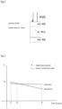
- Fig. 4 shows a graph with the time on the abscissas (or similarly the progression of the number of cycles carried out over the life of the product), while on the ordinates we indicate the Power in KW.
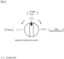
- Fig. 5 shows the electronic control of the induction.
Summary of the invention
-
Therefore the objective of the present implementation is to provide a dish cleaning system which overcomes the aforementioned problems with reference to the prior art and which therefore presents the following advantages:
- have the possibility of reducing heating times at the moment of greatest need for washing dishes/dishes and therefore increasing productivity,
- have the possibility to choose, not only a program or cycle, but also an optimal power configuration setup with maximum energy saving or vice versa with maximum performance;
- increase the precision of the output temperature control with consequent general energy savings;
- do not have electrified elements inside the water heater;
- drastically reduce the creation of limescale inside the heater;
- eliminate limescale problems on the immersed resistance;
- have a long-term energy saving calculated over the life of the product.
-
The solution object of the present invention can be applied in the dishwasher sector in general, both for domestic and professional use.
-
In particular, it is considered particularly suitable for professional dishwashers as the more critical the absolute performances are (maximum speed and effectiveness of a complete washing cycle) and the more this system allows for significant energy savings to be managed over the life of the dishwasher, product, also solving maintenance problems due to limescale deposited on the classic resistors used in the traditional solution.
-
The dishwasher examined as an application example of the present invention is the following: a HoodType
® model (hood) with an 8.5 liter heater. The same considerations as an application example can also be applied to Rack Type
® (dragged basket or conveyor belt tunnel). For different power sizes or models (undercounter, 35-40-50 undercounter, or domestic-type equipment) the numbers simply must be adequate in the application in terms of liters of water, temperature and therefore incoming power. The specifications of the standard starting heater considered here as an exemplary application of the principles of the proposed solution are shown in the following table.
| Cylindrical Boiler |
| Lenght | L = 45 cm = 0.45 m |
| Internal/external radius | rin = 8.13 cm = 0.0813 m |
| rout = 8.25 cm = 0.0825 m |
| Thickness | t = 1.2 mm = 1.2 × 10⁻³ m |
| Metal Volume | V = π(0.08252 - 0.07882) · 0.45 = 2.78 × 10⁻⁴ m 3 = 278 cm 3 |
-
To create the standard reference heater, two different stainless steels were taken into consideration: Steel 430 and Steel 441, with specifications in the table.
| | Stainless steel 430 | Stainless steel 441 |
| Resistivity at 25°C | ρ 430 = 6.2 × 10⁻⁷ Ωm | ρ 441 = 6 × 10⁻⁷ Ωm |
| Density | d 430 = 7.7 g/cm 3 | d 441 = 7.7 g/cm 3 |
| Magnetic permeability | µ r430 = 1500 - 2000 | µ r441 = 1000 - 1500 |
| µ 430 = µ0µr430 | = 2.2 | µ 430 = µ 0 µ r430 = 1.6 × 10⁻³ H/m |
| | × 10-3 H/m | |
| Specific heat | c p430 = 0.480 J/gK | c p441 = 0.460J/gK |
-
Below are the physical specifications of the water used in the application taken into consideration. Note the expected temperature difference from 22 to 85 °C, usually required when using industrial dishwashers to comply with health regulations. However, it can be different based on the needs of the washing cycle defined by the manufacturer on a case-by-case basis.
| Useful data for water use |
| Density | d H2O = 1000 kg/m3 = 1 kg/liter |
| Magnetic permeability | µ = µ 0 = 1.25 × 10⁻⁶ H/m |
| Specific heat | c p441 = 0.460J/gK |
| Convective heat coefficient | h = 50 W/m 2 K |
| Temperature variation | ΔT = 85 - 22 = 63 °C |
-
Consideration. For the sole purpose of describing the basic principles used in the standard reference considerations, we remind you that to heat water from 22 to 85 °C in a time Δt (for example 6 - 9 min) the power required increases as the time decreases:
-
Let us remember that the heat supplied by the piece of metal to the water occurs through convection.
-
The temperature that the internal surface must reach in order to transmit the heat necessary to the water to bring it to 85 ° C in the required time will be:
-
In the specific example case, to heat 8.5 liters of water from 22 to 85 °C in a time of 6 - 9 minutes, the power required increases as the time decreases:
| Tempo | Potenza (W) | Temperatura della suerficie del metallo (°C) |
| 5 min | 7000 | 694 |
| 6 min | 5860 | 594 |
| 7 min | 5020 | 521 |
| 8 min | 4390 | 466 |
| 9 min | 3900 | 424 |
-
Further characteristics and advantages of the dishwasher of the invention will result from the description of the examples of embodiment of the invention, provided as an indication of the invention.
Detailed description of the invention
-
As used herein, the terms "top", "bottom", "right", "left", "back", "front", "vertical", "horizontal" and their derivatives refer to the concepts oriented in Fig. 1.
-
However, it should be understood that the concepts can take various alternative orientations, unless expressly specified to the contrary.
-
As used herein, the term "and/or", when used in a list of two or more items, means that any of the listed items may be employed alone, or in any combination of two or more of the listed items.
-
For example, if a combination is described as containing components A, B and/or C, the combination may only contain A; B only; C only; A and B in combination; A and C in combination; B and C in combination; or A, B and C in combination.
-
The terms "comprises", "comprising" or any other variation thereof, are intended to cover a non-exclusive inclusion, such that a device, process, use, or apparatus comprising a list of elements does not include only those elements but may include other items not expressly listed or inherent to such device, process, use, or apparatus.
-
An element followed by "comprises...a..." does not, without further constraints, prevent the existence of further identical elements in the process, use or apparatus comprising the element.
-
An object of the present invention is a dishwasher (1) comprising:
- a heating reservoir (R) suitable for holding water, and where said heating reservoir comprises an inlet and an outlet for water,
- at least one magnetic induction field-generating filament (C), where said filament is spirally formed, and where said spirally formed filament is placed below the heating reservoir (R),
- a source of high frequency currents (S) capable of generating magnetic induction fields in the at least one filament (C), wherein said source (S) is connected to said at least one filament (C),
- a heat sink (D) placed near the source of high-frequency currents (S).
-
It has in fact been surprisingly found that such a washing machine (1) with the aforementioned combination of elements simultaneously solves the problems with reference to the problems encountered with reference to the prior art.
-
Preferably, in the dishwasher (1) the at least one magnetic induction field generator filament (C) is arranged on a plane.
-
Preferably, the at least one magnetic induction field generating filament (C) is shaped like a concentric spiral.
-
Even more preferably, the at least one magnetic induction field generating filament (C) is arranged on a plane and is shaped like a concentric spiral. Figure 1 shows this preferred embodiment.
-
The washing machine (4) can comprise only one magnetic induction field generator filament (C) or it can comprise several.
-
Preferably, the washing machine (4) comprises only a magnetic induction field generating filament (C).
-
Preferably, the at least one magnetic induction field generating filament (C) is made of trace copper.
-
The heat sink (D) can be made of metal or metal alloy, preferably the heat sink is made of aluminum.
-
Preferably, the dishwasher (1) has side walls and the upper part of the heater tank (R) which are made of AISI 304 stainless steel.
-
Preferably, the lower wall of the heater tank (R), for applications with power lower than 7 Kw, is made, in order from top to bottom, from the following layers of materials:
- a. EN 1.4307,
- b. EN Copper or Copper,
- c. EN 1.4512,
- d. EN 1.4307,
- e. Alluminium 99.5,
- f. EN 1.4307,
- g. Copper,
- h. EN 1.4512,
- i. EN 1.4307;
where the acronyms above indicate specific well-known types of stainless steel.
-
Preferably, the lower wall of the heater tank (R), for applications with power exceeding 7 Kw, is made, in order from top to bottom, from the following layers of materials:
- j. AISI 436,
- k. Alluminium 99.5,
- l. AISI 436.
-
Preferably, the heater tank (R) has a square base, where the size of said square base is such as to entirely cover the at least one magnetic induction field generating filament (C).
-
Said dishwasher (4) further comprises a control unit, where said control unit comprises software configured for the control of the water loading/draining devices as well as the switching on and power modulation of the source (S) of the magnetic inductive field, and where said control unit is connected to a Level Switch (L) and a Thermometer (T) present on the heater tank (R) and furthermore, said control unit is connected to loading/unloading devices of the water as well as the switching on and power modulation of the source (S).
-
Preferably, the source of high frequency currents (S) is suitably cooled by forced air drawn from under the dishwasher and ducted through the heat sink (D).
-
Preferably, where the source of high frequency currents (S) is housed on the bottom of the dishwasher (4).
-
The water heater tank (C) used inside dishwashers to bring the water to temperature (approximately 80-85°C) in the various phases of the wash and rinse cycles, in standard applications uses armored resistors immersed in direct contact with the water itself. Thermal transfer occurs by convection. See figure 1.
-
According to one embodiment, the induction solution involves replacing the classic resistance inside the heater (R) with a spiral-shaped copper braid coil placed under the heater itself (C). The coils will be powered by a high frequency current from a suitable device to generate magnetic induction fields (S). The electronic apparatus generating magnetic induction fields (S) must be adequately cooled by an aluminum heat sink (D).
-
The power entering the system must be able to vary within a range - 50% +200% of the expected average value (100%), in order to be able to select a highly performing program in terms of execution speed (+100% extra power ), a standard program (=100%), or finally an energy saving Eco GREEN program (-50% power compared to the standard). Power control must be continuous in order to optimize the washing programs managed by appropriate dedicated software. It can be either through a mechanical knob or a digital electronic one.
-
The electronic components (S) will be placed on the bottom of the dishwasher and housed in such a way as to avoid accidental contact with water, and at the same time suitably cooled with forced air drawn from under the appliance and channeled through the heat sink (D) .
-
The heater container must be equipped with a level switch (L), thermometer (T), two separate loading and unloading connections to supply cold water and draw water when at temperature. The reading data of the Level Switch and the Thermometer are used by the software program which is responsible for controlling the water loading/unloading devices as well as switching on and power modulation of the magnetic inductive field source. The shape of the heater tank must have a square base in order to cover all the concentric turns of the coil (C). For this reason, the size of the side of the square will be determined mainly by the power of the induction and therefore by the heating power you want. Instead, the height of the tank will be calculated from time to time so that it is suitable for obtaining the required liters of water (volume) from the washing/rinsing cycle of the appliance.
-
The material must be such as to allow tight welding, such as not to be exposed to rust phenomena over time, but also such as to make the thermal transfer of the inductive field effect possible. Basically it must be a magnetic and rust-resistant metal.
-
For these reasons, the side walls and the upper face of the heater tank are made of AISI 304, of a thickness suitable for the size of the structure considered and the maximum water pressures expected during the washing and rinsing cycle phases.
-
The material constituting the base of the tank, in addition to resisting rust, corrosion and allowing tight welding with the AISI 304 walls, must interact correctly with the magnetic induction fields generated by the underlying coil (C). The solution is a special co-laminated metallic material. This is made up of a sandwich of layers of various metals to allow the induction to work correctly but at the same time also make effective and economical welding possible with the AISI 304 walls without incurring corrosive or oxidation phenomena over time. Below 7KW of maximum power of the induction considered, we have verified that the following sandwich of materials is suitable (See Fig. 2):
-
Composition of the material that makes up the layers:
- EN 1.4307,
- EN Copper or Copper,
- EN 1.4512,
- EN 1.4307,
- Alluminium 99.5,
- EN 1.4307,
- Copper,
- EN 1.4512,
- EN 1.4307.
-
The material constituting the base of the tank, in addition to resisting rust, corrosion and allowing tight welding with the AISI 304 walls, must interact correctly with the magnetic induction fields generated by the underlying coil (C). In the case of source powers (S) greater than 7 KW, an optimal configuration of the sandwich has been identified which involves the use of AISI 436 ferromagnetic material which is particularly resistant to phenomena related to rust, but at the same time effective in generating heat once subject to magnetic induction fields. The aluminum sandwiched between the two magnetic layers acts as a device that makes the heat distribution uniform and increases the thermal inertia of the system. This further speeds up the restoration of the target water temperature in the rapid and sequential reiteration of the wash/rinse cycles (if required). If the installed induction power is greater than or equal to 7 kW, a sandwich with the two exposed surfaces in AISI 436 is suitable (see Fig. 3).
-
Composition of the material that makes up the layers:
- AISI 436,
- Alluminium 99.5,
- AISI 436.
-
Therefore according to a preferred embodiment of the dishwasher (1), the source of high frequency currents (S) has a power lower than 7 Kw and the lower wall of the heater tank (R) is made, in order from the top below, from the following layers of materials:
- a. EN 1.4307,
- b. EN Copper or Copper,
- c. EN 1.4512,
- d. EN 1.4307,
- e. Alluminium 99.5,
- f. EN 1.4307,
- g. Copper,
- h. EN 1.4512,
- i. EN 1.4307.
-
Therefore according to another preferred embodiment aspect of the Dishwasher (1), the source of high frequency currents has a power greater than 7 Kw and the lower wall of the heater tank (R) is made, in order from top to bottom , from the following layers of materials:
- j. AISI 436,
- k. Alluminium 99.5,
- l. AISI 436.
-
Therefore according to another preferred embodiment aspect of the dishwasher (1), the source of high frequency currents (S) has a power lower than 7 Kw and the lower wall of the heater tank (R) is made, in order from top to bottom, from the following layers of materials:
- a. EN 1.4307,
- b. EN Copper or Copper,
- c. EN 1.4512,
- d. EN 1.4307,
- e. Alluminium 99.5,
- f. EN 1.4307,
- g. Copper,
- h. EN 1.4512,
- i. EN 1.4307; or,
the source of high frequency currents has a power greater than 7 Kw and the lower wall of the heater tank (R) is made, in order from top to bottom, from the following layers of materials:
- j. AISI 436,
- k. Allumminium 99.5,
- l. AISI 436.
ADVANTAGES 1: LONG TERM ENERGY SAVING
-
Let's consider a graph in Figure 4 with the time on the abscissas (or similarly the progression of the number of cycles carried out in the life of the product), while on the ordinates we indicate the Power in KW.
-
With reference to the use of resistors inside the heater, at the initial time t0 the nominal power Pn supplied is almost entirely transformed into heat with a yield of approximately 99%.
-
Comparing the solution with induction at the same time, the yield is slightly lower, around 93-96%, depending on the case, due to the heat dissipated by the electronic components responsible for transforming the current into high frequency.
-
However, the reality is that as the tests continue with successive cycles, over time the performance of the resistance decays faster than the induction solution.
-
This is mainly linked to the formation of limescale which is particularly accentuated when using the resistance.
-
There will be an instant TB in which the yields of the two systems are equivalent (break-even point). Subsequently the inductive solution becomes more performing. By operating an integral from t0 to the end of life time of the active device tF, the result of the energy yield will be favorable to the solution with induction. This solution is more efficient in the long term from the point of view of energy saving for two main reasons: for the reduction of the negative effects of limescale and for the advantage of versatility which is illustrated below (which allows the use of lower powers when possible ).
ADVANTAGES: VERSATILE USE "GREEN vs HEAVY FAST"
-
It is normal that in general washing equipment the option to choose between different more or less intensive cycles and programs is available. However, these cycles differ from each other in the number of phases, type of phases, pressures and temperatures set, and duration times of each phase or state. Not a continuous modulation of heating power.
-
With the system of the invention, however, the customer is offered an additional possibility beyond the choice of the different cycles (which however remains unchanged). In practice, the customer is given the right to set the equipment to always use it, favoring the speeds in all cycles (and therefore for particularly high-performance use). Or for maximum energy saving use (green). Or for use in line with the average standard performances offered by the market. Therefore, with the use of an induction system it becomes feasible to offer the user 3 extreme setups for using the equipment, which provide a different Nominal Power absorbed in the predetermined water heating phase. In practice, the power that gives energy to the heater tank is also added to the control parameters managed in the cycle phases, and this parameter can oscillate continuously in a range between Pmin=50% and Pmax=200% compared to the power considered standard market average Pstd=100% in equipment similar to the one in question. Regarding the Standard electrical power absorbed by the heater, it can be continuously adjusted until it is reduced by half, or on the contrary increased up to double it. On the user's side this translates into the availability of a selector to set the equipment in STANDARD (Pstd=100%), GREEN (Pmin=50%), HEAVY FAST (Pmax=200%) mode. With this setting you can also set the desired limit of the installed power of the machine at your own discretion based on the peak power available with your meter or on the situation of the simultaneity factor with other uses at different times of the day. For example, when the ovens are also working I might need to set the machine to Pmin, vice versa in a restaurant at the end of the day I would like to speed up washing the dishes with the ovens now off. I can better manage power peaks, performance with maximum speed or maximum energy savings depending on the situation. See Fig. 5.
ADVANTAGES: MAINTENANCE REDUCTION
-
From a construction point of view, in the present solution with Induction we do not find any electrical devices immersed in the water to be heated. This means avoiding the typical encrustation of resistors caused by limescale, and therefore avoids the need to replace them when encrusted. Furthermore, the heating occurs with a much larger contact surface with the water and with less critical temperatures than those detected on the surface of the resistors. All this benefits a lower exposure to the generation of limescale for the same use and characteristics of the water. In all cases where the hardness of the water used is a problem, this system brings significant advantages in reducing maintenance interventions.
-
All the individual pieces making up the washing machine (1) are commercially and individually available on large online commercial platforms and, considering the figures reported here, their assembly does not require further inventive efforts.