JP3671924B2 - Cooking device - Google Patents
Cooking device Download PDFInfo
- Publication number
- JP3671924B2 JP3671924B2 JP2002075727A JP2002075727A JP3671924B2 JP 3671924 B2 JP3671924 B2 JP 3671924B2 JP 2002075727 A JP2002075727 A JP 2002075727A JP 2002075727 A JP2002075727 A JP 2002075727A JP 3671924 B2 JP3671924 B2 JP 3671924B2
- Authority
- JP
- Japan
- Prior art keywords
- steam
- cooking
- water
- container
- water tank
- Prior art date
- Legal status (The legal status is an assumption and is not a legal conclusion. Google has not performed a legal analysis and makes no representation as to the accuracy of the status listed.)
- Expired - Fee Related
Links
Images


Description
【0001】
【発明の属する技術分野】
本発明は一般家庭で使用される誘導加熱を用いた調理器に関するものである。
【0002】
【従来の技術】
従来の家庭用の卓上型調理器は、シーズヒータによって金属製の鍋を加熱し、鍋からの熱伝導により調理物が加熱される構成である。また最近は誘導加熱方式を用い、鍋を電磁誘導により直接加熱する電磁調理器もある。しかしながらこれらの調理器では、鍋に接する面と他方では温度に大きな差があり均一な焼き物調理は困難である。また、蒸すなどの料理では、あらかじめ水を大量に鍋内に入れ、100℃の蒸気で調理するため、調理時間が長くなるなどの課題があった。
【0003】
【発明が解決しようとする課題】
本発明は上記従来の課題を解決するもので、100℃以上の過熱蒸気を用い、水および蒸気をより有効かつ安全に循環させながら、食材の水分を失うことなく早く調理できる簡単な構成の調理器の提供を目的とする。
【0004】
【課題を解決するための手段】
上記目的を達成するための本発明の手段のひとつは、水を供給する水タンクと、前記水タンクから供給された水を加熱する蒸気発生手段と、前記蒸気発生手段からの蒸気をさらに高温に加熱する蒸気過熱手段と、調理容器と、蓋とにより構成され、前記蒸気過熱手段からの過熱蒸気は、調理容器の上部および下部から供給でき、前記調理容器の下部に設けた排水口により結露水を吸収し、フィルタを介して浄水した水を水タンクへ供給するようにしたもので、調理物の均一な調理を可能とする調理器としたものである。
【0005】
これにより、調理容器の上と下とから過熱蒸気を被調理物にあてることができるため、ムラなく調理が行えるものである。
【0006】
【発明の実施の形態】
上記目的を達成するために請求項1記載の発明は、水を供給する水タンクと、前記水タンクから供給された水を加熱する蒸気発生手段と、前記蒸気発生手段からの蒸気をさらに高温に加熱する蒸気過熱手段と、調理容器と、蓋とにより構成され、前記蒸気過熱手段からの過熱蒸気は、調理容器の上部および下部から供給でき、前記調理容器の下部に設けた排水口により結露水を吸収し、フィルタを介して浄水した水を水タンクへ供給するようにしたもので、調理物の均一な調理を可能とする調理器としたものである。これにより、調理容器の上と下とから過熱蒸気を被調理物にあてることができるため、ムラなく調理が行えるものである。
【0007】
さらに、無駄な水の発生や手入れを容易にしたものである。
【0008】
請求項2記載の発明は、排水口へ蒸気を強制的に吸引する吸引ファンを設けて、調理終了時の蓋開閉時に高温の蒸気が漏れることを防ぐようにしたもので、より安全な構成としたものである。
【0009】
請求項3記載の発明は、調理終了後に蒸気過熱手段を停止させ、100℃の蒸気のみを調理容器内に循環させることにより、容器内の汚れに水分を吸着させて汚れを浮かして取りやすくしたものであり、手入れをより簡単としたものである。
【0010】
【実施例】
(実施例1)
以下、本発明の第一および第二の手段の実施例について図面を参照しながら説明する。
【0011】
図1は第一の手段を用いた調理器の構成図である。図1において、1は水タンク、2は蒸気発生手段、3は蒸気過熱手段、4は調理容器、5は蓋、6は調理物をのせる網、7は過熱蒸気発生口、8は筐体である。図1において、水タンク1の水は2の蒸気発生手段に入り、ヒータなどによって加熱される。ここで100℃の蒸気になって、蒸気のみが蒸気過熱手段3に流れ込む。ここで蒸気過熱手段3は発泡金属に加熱コイルが巻かれた構成になっている。そこで蒸気が発泡金属の網の目を通っていく際に、誘導加熱によって高温になった発泡金属から熱が伝わり、100℃以上の高温の過熱蒸気となる。
【0012】
図2にこの装置の回路構成図を示す。図2において、9はヒータ、10はスイッチ、11は加熱コイル、12はスイッチング素子、13はドライブ回路、14は制御回路である。ここで制御回路14から出た制御信号がドライブ回路13に入力され、このドライブ回路によりスイッチング素子12を動作させ、加熱コイル11に高周波電流を流す。この高周波電流による磁界で加熱された発泡金属を通り、過熱された蒸気は流路を通り、調理容器の上部と下部に通した2カ所の過熱蒸気発生口7から調理物に当たるようするものである。この構成で、調理容器4内に均一に過熱蒸気が行き渡り、焼き物や蒸気を用いた蒸し料理などができる。
【0013】
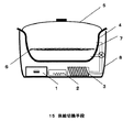
図3は第二の手段を用いた調理器の構成図である。図3の15は供給切換手段である。この供給切換手段15によつて、例えば調理開始が一定時間は蒸気を通さず、蒸気の温度が上がた後に蒸気を通過させることが可能である。また、上下いずれか一方からのみ過熱蒸気を供給することも可能であり、例えば容器に入った冷凍の調理物などの場合は上からのみの蒸気の供給が効率的である。このように供給切換手段15により被調理物に合わせた調理方法が可能となるものである。
【0014】
(実施例2)
以下、本発明の第三、第四および第五の手段の実施例について図面を参照しながら説明する。図4、図5、図6は調理器の構成図である。
【0015】
図4において、1は水タンク、2は蒸気発生手段、3は蒸気過熱手段、4は調理容器、5は蓋、6は調理物をのせる網、7は過熱蒸気発生口、8は筐体、16は調理容器の加熱手段である。調理容器全体が低温の場合、過熱蒸気は調理容器へ入りすぐに結露してしまう。これを防ぐために、アルミニウム製などの調理容器にヒータなどからなる加熱手段16を埋め込むかあるいは接触させ、容器の温度を100℃以上に保つことで、過熱蒸気は温度低下がなく被調理物に熱を伝え、様々な料理がおいしくできるものである。
【0016】
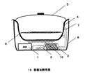
また図5のように、フィルタ18を介して、結露水を回収して浄化させ、再度過熱蒸気として用いると省エネにもなり、全体としての高効率かが図れる。
【0017】
(実施例3)
以下、本発明の第六、第七の実施例について図面を参照しながら説明する。図7、図8は調理器の構成図である。図7において、1は水タンク、2は蒸気発生手段、3は蒸気過熱手段、4は調理容器、5は蓋、6は調理物をのせる網、7は過熱蒸気発生口、8は筐体、18はフィルタ、19は吸引ファンである。図7において、水タンク1の水は2の蒸気発生手段に入り、ヒータなどによって加熱される。ここで100℃の蒸気になって、蒸気のみが蒸気過熱手段3に流れ込む。ここで蒸気過熱手段3により蒸気は100℃以上の高温の過熱蒸気となる。そして調理物にあたって、調理が可能となる。この際、調理終了後も調理容器4内には蒸気や過熱蒸気が充満しており、蓋を開ける際に火傷の恐れもある。そこで吸引ファン19によって容器内の蒸気を急速に回収しフィルタ18を介して浄化することで再利用が可能とする。この構成により、より安全な構成の調理器を提供できるものである。
【0018】
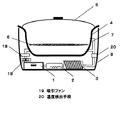
(実施例4)
以下、本発明の第七の実施例について図面を参照しながら説明する。図8は調理器の構成図である。図8において、1は水タンク、2は蒸気発生手段、3は蒸気過熱手段、4は調理容器、5は蓋、6は調理物をのせる網、7は過熱蒸気発生口、8は筐体、18はフィルタ、19は吸引ファン、20は温度検出手段である。吸引ファンにより蒸気がなくなり、使用者が出来上がった調理物を取り出した後、温度検出手段22で蒸気の温度が100℃一定となる状態で、この蒸気を容器内に送る。この送られた蒸気によって容器内の網などに付着した汚れに蒸気がつき、汚れを浮かすことによって、皿に手入れのしやすい調理器を提供できるものである。
【0019】
【発明の効果】
以上のように、請求項1記載の発明では、調理容器の上と下とから過熱蒸気を被調理物にあてることができるため、ムラなく調理が行えるものである。
【0020】
さらに、フィルタを介して水を循環させることで、水の有効利用と省エネが図れるものである。
【0021】
請求項2記載の発明では、ファンで強制的に循環させることができるため、調理終了時に庫内の蒸気を一気に回収でき、蓋を開けても熱く感じなくできるものである。
【0022】
請求項3記載の発明では、蒸気を強制的に吹き付けて汚れが浮き、掃除しやすくなるものである。
【図面の簡単な説明】
【図1】 本発明の第1の手段の実施例における調理器の一例を示す構成図
【図2】 本発明の第1の手段の実施例における調理器の回路構成図
【図3】 本発明の第2の手段の実施例における調理器の一例を示す構成図
【図4】 本発明の第3の手段の実施例における調理器の一例を示す構成図
【図5】 本発明の第4の手段の実施例における調理器の一例を示す構成図
【図6】 本発明の第5の手段の実施例における調理器の一例を示す構成図
【図7】 本発明の第6の手段の実施例における調理器の一例を示す構成図
【図8】 本発明の第7の手段の実施例における調理器の一例を示す構成図
【符号の説明】
1 水タンク
2 蒸気発生手段
3 蒸気過熱手段
4 調理容器
5 蓋
6 網
7 過熱蒸気発生口
8 筐体
9 第一のヒータ
10 第一のスイッチ
11 加熱コイル
12 スイッチング素子
13 ドライブ回路
14 制御回路
15 第二のヒータ
16 第二のスイッチ
17 ファン
18 冷却ファン
19 熱回収伝達手段
20 水タンク
21 加熱手段
22 温度検出手段[0001]
BACKGROUND OF THE INVENTION
The present invention relates to a cooker using induction heating used in general households.
[0002]
[Prior art]
A conventional household tabletop cooker has a configuration in which a metal pan is heated by a sheathed heater, and a cooked product is heated by heat conduction from the pan. Recently, there is also an electromagnetic cooker that uses an induction heating method to directly heat a pan by electromagnetic induction. However, in these cookers, there is a large difference in temperature between the surface in contact with the pan and the other side, and uniform baking is difficult. In addition, in cooking such as steaming, a large amount of water is put in a pan in advance and cooking is performed with steam at 100 ° C., so that there is a problem that the cooking time becomes long.
[0003]
[Problems to be solved by the invention]
SUMMARY OF THE INVENTION The present invention solves the above-described conventional problems, and uses a superheated steam of 100 ° C. or higher, and has a simple structure that can be cooked quickly without losing moisture of the ingredients while circulating water and steam more effectively and safely. The purpose is to provide vessels.
[0004]
[Means for Solving the Problems]
One of the means of the present invention for achieving the above object includes a water tank for supplying water, a steam generating means for heating the water supplied from the water tank, and the steam from the steam generating means at a higher temperature. It comprises a steam superheating means for heating, a cooking container, and a lid, and the superheated steam from the steam superheating means can be supplied from the upper part and the lower part of the cooking container, and dew condensation water is provided by a drain outlet provided at the lower part of the cooking container. In this case, water that has been purified is supplied to a water tank through a filter, and a cooker that enables uniform cooking of cooked food is provided.
[0005]
Thereby, since superheated steam can be applied to a to-be-cooked object from the upper and lower sides of a cooking container, it can cook evenly.
[0006]
DETAILED DESCRIPTION OF THE INVENTION
In order to achieve the above object, the invention described in
[0007]
In addition , wastewater is easily generated and maintained.
[0008]
The invention according to
[0009]
The invention according to
[0010]
【Example】
(Example 1)
Embodiments of the first and second means of the present invention will be described below with reference to the drawings.
[0011]
FIG. 1 is a block diagram of a cooking device using the first means. In FIG. 1, 1 is a water tank, 2 is a steam generating means, 3 is a steam superheating means, 4 is a cooking vessel, 5 is a lid, 6 is a net for placing food, 7 is a superheated steam generating port, and 8 is a housing. It is. In FIG. 1, water in a
[0012]
FIG. 2 shows a circuit configuration diagram of this apparatus. In FIG. 2, 9 is a heater, 10 is a switch, 11 is a heating coil, 12 is a switching element, 13 is a drive circuit, and 14 is a control circuit. Here, a control signal output from the
[0013]
FIG. 3 is a block diagram of a cooking device using the second means. Reference numeral 15 in FIG. 3 denotes supply switching means. By this supply switching means 15, for example, the start of cooking does not pass steam for a certain period of time, and it is possible to allow steam to pass after the temperature of the steam rises. It is also possible to supply superheated steam only from either one of the upper and lower sides. For example, in the case of a frozen food in a container, it is efficient to supply steam only from above. In this way, the supply switching means 15 enables a cooking method according to the food to be cooked.
[0014]
(Example 2)
Embodiments of the third, fourth and fifth means of the present invention will be described below with reference to the drawings. 4, 5 and 6 are block diagrams of the cooking device.
[0015]
In FIG. 4, 1 is a water tank, 2 is steam generating means, 3 is steam superheating means, 4 is a cooking container, 5 is a lid, 6 is a net on which food is placed, 7 is a superheated steam generating port, and 8 is a housing. , 16 is a heating means of the cooking container. When the entire cooking container is cold, the superheated steam enters the cooking container and immediately condenses. In order to prevent this, the heating means 16 such as a heater is embedded in or brought into contact with a cooking container made of aluminum or the like, and the temperature of the container is kept at 100 ° C. or higher, so that the superheated steam does not decrease the temperature and heats the object to be cooked. , And you can make various dishes delicious .
[0016]
Further, as shown in FIG. 5, when condensed water is collected and purified through the
[0017]
(Example 3)
Hereinafter, sixth and seventh embodiments of the present invention will be described with reference to the drawings. 7 and 8 are configuration diagrams of the cooking device. In FIG. 7, 1 is a water tank, 2 is steam generating means, 3 is steam superheating means, 4 is a cooking container, 5 is a lid, 6 is a net for placing food, 7 is a superheated steam generating port, and 8 is a housing. , 18 is a filter, and 19 is a suction fan. In FIG. 7, the water in the
[0018]
(Example 4)
The seventh embodiment of the present invention will be described below with reference to the drawings. FIG. 8 is a block diagram of the cooking device. In FIG. 8, 1 is a water tank, 2 is steam generating means, 3 is steam superheating means, 4 is a cooking container, 5 is a lid, 6 is a net on which food is placed, 7 is a superheated steam generating port, and 8 is a housing. , 18 are filters, 19 is a suction fan, and 20 is a temperature detecting means. After the steam is exhausted by the suction fan and the user takes out the cooked product, the steam is sent into the container in a state where the temperature of the steam is kept constant at 100 ° C. by the temperature detecting means 22. The steam is attached to the dirt attached to the net or the like in the container by the sent steam, and the dirt is lifted to provide a cooking device that is easy to care for the dish.
[0019]
【The invention's effect】
As described above, according to the first aspect of the present invention, since the superheated steam can be applied to the cooking object from above and below the cooking container, cooking can be performed without unevenness.
[0020]
Furthermore, effective use of water and energy saving can be achieved by circulating water through a filter.
[0021]
In the invention of
[0022]
In invention of
[Brief description of the drawings]
FIG. 1 is a block diagram showing an example of a cooking device in an embodiment of the first means of the present invention. FIG. 2 is a circuit configuration diagram of a cooking device in an embodiment of the first means of the present invention. FIG. 4 is a block diagram showing an example of a cooker in the embodiment of the second means of the present invention. FIG. 4 is a block diagram showing an example of a cooker in the embodiment of the third means of the present invention. FIG. 6 is a block diagram showing an example of a cooker in the fifth embodiment of the present invention. FIG. 7 is a block diagram showing an example of a cooker in the fifth embodiment of the present invention. FIG. 8 is a block diagram showing an example of a cooking device in FIG. 8. FIG. 8 is a block diagram showing an example of a cooking device in an embodiment of the seventh means of the present invention.
DESCRIPTION OF
Claims (3)
Priority Applications (1)
| Application Number | Priority Date | Filing Date | Title |
|---|---|---|---|
| JP2002075727A JP3671924B2 (en) | 2002-03-19 | 2002-03-19 | Cooking device |
Applications Claiming Priority (1)
| Application Number | Priority Date | Filing Date | Title |
|---|---|---|---|
| JP2002075727A JP3671924B2 (en) | 2002-03-19 | 2002-03-19 | Cooking device |
Publications (2)
| Publication Number | Publication Date |
|---|---|
| JP2003265317A JP2003265317A (en) | 2003-09-24 |
| JP3671924B2 true JP3671924B2 (en) | 2005-07-13 |
Family
ID=29204724
Family Applications (1)
| Application Number | Title | Priority Date | Filing Date |
|---|---|---|---|
| JP2002075727A Expired - Fee Related JP3671924B2 (en) | 2002-03-19 | 2002-03-19 | Cooking device |
Country Status (1)
| Country | Link |
|---|---|
| JP (1) | JP3671924B2 (en) |
Families Citing this family (2)
| Publication number | Priority date | Publication date | Assignee | Title |
|---|---|---|---|---|
| JP4589819B2 (en) * | 2005-06-20 | 2010-12-01 | 株式会社東芝 | Cooking equipment |
| JP6240990B2 (en) * | 2016-03-31 | 2017-12-06 | 深▲せん▼市沢智知識産権有限公司 | Cooking equipment |
-
2002
- 2002-03-19 JP JP2002075727A patent/JP3671924B2/en not_active Expired - Fee Related
Also Published As
| Publication number | Publication date |
|---|---|
| JP2003265317A (en) | 2003-09-24 |
Similar Documents
| Publication | Publication Date | Title |
|---|---|---|
| US8420983B2 (en) | Vapor cooker | |
| CN105686615B (en) | The control method of cooking apparatus and the control system of cooking apparatus | |
| CN108652433B (en) | Method for cooking rice and electromagnetic heating cooking appliance | |
| JP3156398U (en) | Induction machine | |
| CN110250939B (en) | Control method and device for steaming and baking oven and steaming and baking oven | |
| CN108567313A (en) | Cooking control method and cooking apparatus for cooking apparatus | |
| JP2003144308A5 (en) | ||
| JP3671924B2 (en) | Cooking device | |
| JP2000184964A (en) | Heating and steaming cooker | |
| JP3832134B2 (en) | Superheated steam cooker | |
| CN112120523A (en) | Cooking method, cooking utensil and cooking device | |
| JPH0322642Y2 (en) | ||
| CN210748671U (en) | All-in-one machine with cooking and cleaning functions | |
| CN209058789U (en) | A kind of penetration heating boiling multi-purpose pot | |
| JP2004187725A (en) | Heating device using superheated steam | |
| CN115813193B (en) | Intelligent partition temperature control steaming and baking oven | |
| JP2003272810A (en) | Induction heating cooker | |
| KR0185618B1 (en) | Cooker | |
| JP2004065536A (en) | Cooker | |
| KR200385125Y1 (en) | Soup carrying cart | |
| JP2024053842A (en) | Heating Cooker | |
| JP3069225U (en) | Food frying equipment | |
| JP2002291617A (en) | Electric rice cooker | |
| KR200284760Y1 (en) | A hotplate for cook | |
| CN2285607Y (en) | Electric quick steaming pot |
Legal Events
| Date | Code | Title | Description |
|---|---|---|---|
| A621 | Written request for application examination |
Free format text: JAPANESE INTERMEDIATE CODE: A621 Effective date: 20040604 |
|
| A977 | Report on retrieval |
Free format text: JAPANESE INTERMEDIATE CODE: A971007 Effective date: 20041029 |
|
| A131 | Notification of reasons for refusal |
Free format text: JAPANESE INTERMEDIATE CODE: A131 Effective date: 20041116 |
|
| A521 | Written amendment |
Free format text: JAPANESE INTERMEDIATE CODE: A523 Effective date: 20050107 |
|
| TRDD | Decision of grant or rejection written | ||
| A01 | Written decision to grant a patent or to grant a registration (utility model) |
Free format text: JAPANESE INTERMEDIATE CODE: A01 Effective date: 20050329 |
|
| A61 | First payment of annual fees (during grant procedure) |
Free format text: JAPANESE INTERMEDIATE CODE: A61 Effective date: 20050411 |
|
| FPAY | Renewal fee payment (event date is renewal date of database) |
Free format text: PAYMENT UNTIL: 20080428 Year of fee payment: 3 |
|
| FPAY | Renewal fee payment (event date is renewal date of database) |
Free format text: PAYMENT UNTIL: 20090428 Year of fee payment: 4 |
|
| FPAY | Renewal fee payment (event date is renewal date of database) |
Free format text: PAYMENT UNTIL: 20100428 Year of fee payment: 5 |
|
| FPAY | Renewal fee payment (event date is renewal date of database) |
Free format text: PAYMENT UNTIL: 20110428 Year of fee payment: 6 |
|
| FPAY | Renewal fee payment (event date is renewal date of database) |
Free format text: PAYMENT UNTIL: 20120428 Year of fee payment: 7 |
|
| FPAY | Renewal fee payment (event date is renewal date of database) |
Free format text: PAYMENT UNTIL: 20130428 Year of fee payment: 8 |
|
| FPAY | Renewal fee payment (event date is renewal date of database) |
Free format text: PAYMENT UNTIL: 20130428 Year of fee payment: 8 |
|
| FPAY | Renewal fee payment (event date is renewal date of database) |
Free format text: PAYMENT UNTIL: 20140428 Year of fee payment: 9 |
|
| LAPS | Cancellation because of no payment of annual fees |