EP4576701A1 - Kommunikationsverfahren und -vorrichtung - Google Patents
Kommunikationsverfahren und -vorrichtung Download PDFInfo
- Publication number
- EP4576701A1 EP4576701A1 EP24216457.2A EP24216457A EP4576701A1 EP 4576701 A1 EP4576701 A1 EP 4576701A1 EP 24216457 A EP24216457 A EP 24216457A EP 4576701 A1 EP4576701 A1 EP 4576701A1
- Authority
- EP
- European Patent Office
- Prior art keywords
- network device
- software version
- issu
- version upgrade
- backup
- Prior art date
- Legal status (The legal status is an assumption and is not a legal conclusion. Google has not performed a legal analysis and makes no representation as to the accuracy of the status listed.)
- Pending
Links
Images

Classifications
-
- H—ELECTRICITY
- H04—ELECTRIC COMMUNICATION TECHNIQUE
- H04L—TRANSMISSION OF DIGITAL INFORMATION, e.g. TELEGRAPHIC COMMUNICATION
- H04L41/00—Arrangements for maintenance, administration or management of data switching networks, e.g. of packet switching networks
- H04L41/06—Management of faults, events, alarms or notifications
- H04L41/0654—Management of faults, events, alarms or notifications using network fault recovery
- H04L41/0663—Performing the actions predefined by failover planning, e.g. switching to standby network elements
-
- H—ELECTRICITY
- H04—ELECTRIC COMMUNICATION TECHNIQUE
- H04L—TRANSMISSION OF DIGITAL INFORMATION, e.g. TELEGRAPHIC COMMUNICATION
- H04L41/00—Arrangements for maintenance, administration or management of data switching networks, e.g. of packet switching networks
- H04L41/08—Configuration management of networks or network elements
- H04L41/0866—Checking the configuration
- H04L41/0869—Validating the configuration within one network element
-
- G—PHYSICS
- G06—COMPUTING OR CALCULATING; COUNTING
- G06F—ELECTRIC DIGITAL DATA PROCESSING
- G06F8/00—Arrangements for software engineering
- G06F8/60—Software deployment
- G06F8/65—Updates
-
- H—ELECTRICITY
- H04—ELECTRIC COMMUNICATION TECHNIQUE
- H04L—TRANSMISSION OF DIGITAL INFORMATION, e.g. TELEGRAPHIC COMMUNICATION
- H04L67/00—Network arrangements or protocols for supporting network services or applications
- H04L67/01—Protocols
- H04L67/10—Protocols in which an application is distributed across nodes in the network
- H04L67/1095—Replication or mirroring of data, e.g. scheduling or transport for data synchronisation between network nodes
-
- H—ELECTRICITY
- H04—ELECTRIC COMMUNICATION TECHNIQUE
- H04L—TRANSMISSION OF DIGITAL INFORMATION, e.g. TELEGRAPHIC COMMUNICATION
- H04L67/00—Network arrangements or protocols for supporting network services or applications
- H04L67/2866—Architectures; Arrangements
- H04L67/30—Profiles
-
- H—ELECTRICITY
- H04—ELECTRIC COMMUNICATION TECHNIQUE
- H04L—TRANSMISSION OF DIGITAL INFORMATION, e.g. TELEGRAPHIC COMMUNICATION
- H04L67/00—Network arrangements or protocols for supporting network services or applications
- H04L67/34—Network arrangements or protocols for supporting network services or applications involving the movement of software or configuration parameters
-
- H—ELECTRICITY
- H04—ELECTRIC COMMUNICATION TECHNIQUE
- H04L—TRANSMISSION OF DIGITAL INFORMATION, e.g. TELEGRAPHIC COMMUNICATION
- H04L41/00—Arrangements for maintenance, administration or management of data switching networks, e.g. of packet switching networks
- H04L41/06—Management of faults, events, alarms or notifications
- H04L41/0654—Management of faults, events, alarms or notifications using network fault recovery
- H04L41/0668—Management of faults, events, alarms or notifications using network fault recovery by dynamic selection of recovery network elements, e.g. replacement by the most appropriate element after failure
-
- H—ELECTRICITY
- H04—ELECTRIC COMMUNICATION TECHNIQUE
- H04L—TRANSMISSION OF DIGITAL INFORMATION, e.g. TELEGRAPHIC COMMUNICATION
- H04L41/00—Arrangements for maintenance, administration or management of data switching networks, e.g. of packet switching networks
- H04L41/08—Configuration management of networks or network elements
- H04L41/0803—Configuration setting
- H04L41/0813—Configuration setting characterised by the conditions triggering a change of settings
- H04L41/082—Configuration setting characterised by the conditions triggering a change of settings the condition being updates or upgrades of network functionality
Definitions
- the present disclosure relates to the technical field of communication, in particular to a communication method and apparatus.
- a stacking technology is to manage and control multiple network devices as a whole to improve the reliability and flexibility of network devices.
- multiple network devices are allowed to behave as a single logical device in regard of the actual physical connection.
- the above stacking technology usually consist of two or more network devices, one of which is a master device and the other of which are slave devices.
- a distributed system is constructed between the master and slave devices.
- the distributed system is similar to a modular device, and data is synchronized among individual network devices according to a distributed model, so as to realize the cooperative work, unified management and uninterrupted maintenance of multiple network devices.
- ISSU In-Service Software Upgrade
- a network device without interrupting a currently running network traffic service.
- ISSU can improve the reliability and flexibility of an upgrade process, and avoid an impact of traffic interruption on the network.
- ISSU is centered on a slave device to proceed.
- the specific upgrade process is as follows: a slave device upgrades its own software version firstly, then restarts using a new version; after the restart, data between a master device and the slave device is synchronized between the master device and the slave device through a highly available cluster (abbreviated as: HA) channel, and a data compatibility between the master device and the slave device is ensured (the data compatibility means that a structure of the data changes and the change in the structure does not affect the processing of the data, the old version ignores the newly defined data included in a received message, and the new version uses a default value for an unassigned field included in the received message), then, the original master device upgrades its own software version, and restarts using the new version, and the original slave device is upgraded to a new master device; finally, the original master device, after restarting, plays a role of a new slave device and forms a stacking with the new master device.
- HA highly available cluster
- the master and slave devices are in a state of running across versions.
- Data needs to be backed up between master and slave devices to ensure that the slave device can carry traffic flow.
- the data structure and processing time sequence may be different between different versions due to an introduction of new characteristics, problem modification, etc. Therefore, ISSU also suffers from the following issues: high requirements for programming, special consideration for data and processing compatibility, and lack of verification means.
- versions of the same branch is often required to be compatible with each other for a fairly long period of time (e.g., 18 months).
- the existing solution is to use a distributed architecture, that is, the master and slave devices are still regularly stacked during the cross-version operation.
- Data is backed up between master and slave devices through regular distributed channels (e.g., HA channel, unicast and multicast channels between devices, etc.), and backup modes include real-time backup and batch backup.
- Backup data includes configuration, protocol status, forwarding entries, statistics, events, etc.
- the modification of a synchronization message can be standardized, uniformly defined, serialized and de-serialized.
- the present disclosure provides a communication method and apparatus to solve the issue of incompatibility of processing time sequence and heavy test workload in the existing ISSU upgrade process.
- the present disclosure provides a communication method applied to a first network device, wherein the first network device is in a stacking system and is a slave device in the stacking system, the stacking system further includes a second network device that is a master device in the stacking system, a distributed system is formed between the first network device and the second network device, the first network device performs a software version upgrade and restarts, the method including:
- the present disclosure provides a communication apparatus applied to a first network device, wherein the first network device is in a stacking system and is a slave device in the stacking system, the stacking system further includes a second network device that is a master device in the stacking system, a distributed system is formed between the first network device and the second network device, the first network device performs a software version upgrade and restarts, the apparatus including:
- the present disclosure provides a network device, including a processor and a machine readable storage medium having a machine executable instruction that can be executed by the processor stored therein, wherein the machine executable instruction causes the processor to execute the method provided in the first aspect of the present disclosure.
- no stacking system is formed between the first network device and the second network device in response to determining that a first software version of the first network device after the software version upgrade is different from a second software version of the second network device and the first network device is in an ISSU period; the first network device obtains an ISSU role of the first network device; an ISSU backup channel is established with the second network device in response to determining that the ISSU role is a slave node; the first network device receives configuration files and first backup data sent by the second network device through the ISSU backup channel; the first network device restores a local configuration and first traffic data according to the configuration files and the first backup data; wherein, the first network device after the software version upgrade and the second network device are respectively in different distributed systems, and are master devices in their respective distributed systems.
- the first network device and the second network device operate in a dual-machine mode during the cross-version operation.
- Each network device is the master device in a distributed system of the network device itself.
- the first network device restores configurations of all modules and restores the forwarded traffic data of traffic modules, without considering the configuring time sequence between traffic modules.
- the structure of the backup data can be solidified, so that in the software version upgrade interval, the data structure of backup data synchronized between different versions is no longer changed, which reduces the test workload, and solves the issue of incompatibility of processing time sequence and heavy test workload in the existing ISSU upgrade process.
- first, second, third, etc. may be used to describe various information in the present disclosure, the information should not be limited to these terms. These terms are used only to distinguish information of the same type from each other.
- first information may also be referred to as the second information, and similarly the second information may be referred to as the first information.
- the word "if' used here can be interpreted as "while", "when” or "in response to determining”.
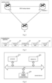
- Fig. 1 is a diagram of a communication method provided in an example of the present disclosure. The method is applied to a first network device, and the communication method provided by the example of the present disclosure may include the following blocks.
- Block 110 forming no stacking system between the first network device and the second network device in response to determining that a first software version of the first network device after a software version upgrade is different from a second software version of a second network device and the first network device is in an ISSU period;
- the first network device is in a stacking system, and the stacking system further includes the second network device.
- the second network device is a master device in the stacking system, and the first network device is a slave device in the stacking system.
- a distributed system is formed between the first network device and the second network device.
- the distributed system is similar to a modular device, and data is synchronized among individual network devices according to a distributed model, so as to realize the cooperative work, unified management and uninterrupted maintenance of multiple network devices.
- the first network device performs a software version upgrade, i.e., ISSU, according to an upgrade instruction input by a manager. After the software version upgrade, the first network device restarts.
- a software version upgrade i.e., ISSU
- the first network device After the first network device restarts, the first network device establishes a communication connection with the second network device and interactively negotiates with the second network device for a device attribute. In the process of interactive negotiation, the first network device obtains the second software version of the second network device, an ISSU role of the second network device and other information.
- the first network device obtains its own first software version and identifies whether the first software version is the same as the second software version.
- the first network device identifies whether it is currently in the ISSU period (that is, each network device in the stacking system upgrades its own software version in order, where the slave device updates firstly, and then the master device updates, and a software upgrade period of the network device is called the ISSU period) in response to determining that the first software version is different from the second software version.
- the first network device no longer constructs an existing stacking system with the second network device in response to determining that the first network device is in the ISSU period.
- the above communication connection is specifically a physical communication channel, that is, a physical connection inserted between the first network device and the second network device.
- Block 120 obtaining an ISSU role of the first network device
- the first network device obtains its own ISSU role.
- the ISSU role includes a master node and a slave node. This ISSU role is specified and configured by the manager when the first network device and the second network device form the stacking system.
- Block 130 establishing an ISSU backup channel with the second network device in response to determining that the ISSU role is a slave node;
- the first network device identifies the ISSU role.
- the first network device establishes an ISSU backup channel with the second network device in response to determining that the ISSU role is a slave node.
- the ISSU backup channel is a logical channel established on the physical communication channel.
- the first network device exits the stacking system constructed previously by the first network device and the second network device once the first network device has restarted.
- the first network device automatically acts as a master device in another distributed system that is different from the distributed system in which the second network device is located.
- the second network device After the first network device establishes the ISSU backup channel with the second network device, the second network device obtains all the stored configuration files and first backup data to be backed up of traffic modules of the second network device itself. The second network device sends the configuration files as well as the first backup data to the first network device through the ISSU backup channel.
- the second network device determines that the first network device has upgraded the software version, which is different from a local software version.
- the second network device can firstly obtain a local configuration file and send an event notification to each local traffic module to inform the traffic module that the first network device has upgraded the software version, and each traffic module collects its own backup data (also known as partial backup data). After all of the traffic modules have finished the collection, the second network device integrates individual pieces of partial backup data into the first backup data (also known as whole backup data).
- the above backup data collected by each traffic module is specifically the necessary backup data to maintain a traffic function by itself, such as a forwarding table, a routing table and so on included in a protocol module; and user authentication data and so on included in an authentication module.
- Block 140 receiving configuration files and first backup data sent by the second network device through the ISSU backup channel;
- the first network device receives the configuration files and the first backup data sent by the second network device.
- the configuration files and the first backup data can be sent to the first network device at the same time; alternatively, the configuration file and the first backup data can be sent to the first network device in multiple times.
- Block 150 restoring a local configuration and first traffic data according to the configuration files and the first backup data
- the first network device restores the local configuration firstly according to the configuration files.
- the local configuration includes a global configuration (an underlying software and hardware resource allocation, an interface configuration, a communication protocol, etc.) and a traffic configuration (an attribute of a traffic module, a traffic function, etc.). Then, the first traffic data in the traffic modules is restored according to the first backup data.
- the traffic modules being various protocol modules is taken as an example for description, such as routing, STP, and so on.
- the current configuration of the first network device is the same as the current configuration of the second network device (for example, a loopback interface address, rooter-id of route, etc.), therefore, in order to avoid protocol confusion caused by the subsequent simultaneous operation, the first network device and the second network device can behave as one protocol entity externally, and various protocols need to be processed centrally in one network device.
- the protocol module runs in the ISSU master node, and after the ISSU slave node receives a protocol packet, the ISSU slave node passes through the protocol packet to the ISSU master node, to be processed by the ISSU master node.
- the first network device puts a protocol state machine, an aging timer, a forwarding table, and a routing table included in a protocol module of the first network device in a suspended state according to the ISSU slave node identity. Since the above functions are all in a suspended state, the first network device only enables a transceiver function of an interface, and after the first network device receives a data packet, the first network device also passes through the data packet to the second network device to be processed by the second network device.
- the method further includes a process of the second network device registering its own interface with the first network device.
- the first network device sends an interface registration message to the second network device through the ISSU backup channel in response to determining that the local configuration and the first traffic data are restored, where the interface registration message includes an interface attributes of each interface included in the first network device; the first network device sets each interface included in the first network device to an enabled (UP) state, to cause each interface to receive or send a packet.
- UP enabled
- the ISSU master node in order to pass through all types of packets (protocol packet and data packet) received by the slave node to the ISSU master node, the ISSU master node should be able to know an interface of the ISSU slave node, so that each traffic module in the ISSU master node can normally process the passed-through packets. Therefore, it is necessary to register the interface included in the first network device as an optical board interface with the second network device, that is, for the second network device, the interface included in the first network device is extension of an interface included in the second network device.
- the above optical board interface can be considered as a special extension interface, and no software system is configured in the optical board.
- the second network device can consider each physical interface included in the first network device as an interface of the second network device itself.
- the method further includes a process of pass through of a packet from a first network device to a second network device to be centrally processed by the second network device.
- the first network device includes a first interface, and the first interface has been registered with the second network device according to the preceding procedure.
- the first network device firstly determines its ISSU identity in response to determining that the first network device receives a first packet sent by a third network device through the first interface.
- the first network device sends the first packet to the second network device through the ISSU backup channel in response to determining that the ISSU identity is an ISSU slave node, to cause the second network device to process the first packet accordingly;
- the first network device receives a second packet obtained after the second network device processes the first packet accordingly, through the ISSU backup channel; the first network device sends the second packet to the third network device through the first interface.
- the above first packet and the second packet can be specifically a protocol packet or a data packet.
- the traffic flow can be jointly carried and served by the first network device and the second network device, and be centrally processed by the second network device.
- the method further includes a process of sending backup data to the first network device again before the second network device performs a software version upgrade and restarts.
- the second network device obtains second backup data of its own traffic modules to be backed up.
- the second network device sends the second backup data to the first network device through the ISSU backup channel.
- the first network device After the first network device receives the second backup data, the first network device stores the second backup data in a corresponding traffic module.
- the second network device sends the second backup data to the first network device again before restarting.
- the method further includes a process of the first network device negotiates with the second network device after the software version upgrade again to form a stacking system.
- the first network device establishes a communication connection with the second network device after the software version upgrade again, and interactively negotiates with the second network device after the software version upgrade for a device attribute.
- the first network device and the second network device after the software version upgrade form a stacking system again.
- the second network device after the software version upgrade is a slave device in the stacking system
- the first network device is a master device in the stacking system.
- a distributed system is formed again between the master device and the slave device, and a distributed channel (e.g., HA channel, inter-board channel (IBC), unicast and multicast channels, etc.) is established between the first network device and the second network device after the software version upgrade.
- a distributed channel e.g., HA channel, inter-board channel (IBC), unicast and multicast channels, etc.
- the third backup data is sent to the second network device through the distributed channel, to cause the second network device to store the third backup data locally.
- the first network device after the software version upgrade and the second network device after the software version upgrade are in the same distributed system, and the first network device after the software version upgrade is a master device in the distributed system, and the second network device after the software version upgrade is a slave device in the distributed system.
- the traffic flow is carried and processed by the first network device during restart of the second network device.
- the above process of forming a stacking system again, electing a master role and a slave role within the stacking system, and the master device and the slave device forming a distributed system are the same as the existing process and will not be repeated here.
- backup data sent for each software version after software version upgrade has a same data structure in response to determining that a software version of the first network device and a software version of the second network device are in the same software version upgrade interval.
- Backup data sent for each software version after software version upgrade has a different data structure in response to determining that the software version of the first network device and the software version of the second network device are in different software version upgrade intervals.
- the above process specifically refers to a structure solidified process of backup data.
- the software version upgrade interval specifically refers to a version cycle. For example, every 10 versions constitute a version cycle. Within the cycle of 10 versions, when the network devices are in any two versions, data structures of all backup data sent between the network devices during the ISSU period are the same. Because the data structures are the same, there is no need to cross-test all versions.
- the software version upgrade interval is [1,10], that is, Version 1 to Version 10 is a software version upgrade interval.
- the software version of the first network device is Version 5
- the software version of the second network device is Version 10. At this time, data structures of all backup data sent between the network devices are the same.
- the software version upgrade interval 1 is [1,10]
- the software version upgrade interval 2 is [11,20].
- Data structures of all backup data sent between the network devices are different in response to determining that the software version of the first network device is Version 11, and the software version of the second network device is Version 5.
- a manager needs to select any version from the previous software version upgrade interval [1,10] (Version 1 to Version 10 are available for selecting), to conduct a compatibility test with Version 11 within the current software version upgrade interval [11,20]. Therefore, there is no need to cross-test all versions, thus reducing the test workload.
- the test mentioned above is specifically a compatibility test process led by a manager. That is, at the beginning of the software version upgrade of each network device, the manager knows that a current software version of each network device is to be upgraded and knows a next software version to which the current software version will be upgraded to. Therefore, the manager initiates a compatibility test in response to determine that the manager determines that the upgraded software version of the first network device and the current software version of the second network device are in different software version upgrade intervals.
- each network device can temporarily store the backup data in a local traffic module, and try to read, study and run the backup data with different data structures, determine the issue and a location where an error occurs, so as to improve the new software version in the future.
- no stacking system is formed between the first network device and the second network device in response to determining that a first software version of the first network device after the software version upgrade is different from a second software version of the second network device and the first network device is in an ISSU period; the first network device obtains an ISSU role of the first network device; an ISSU backup channel is established with the second network device in response to determining that the ISSU role is a slave node; the first network device receives configuration files and first backup data sent by the second network device through the ISSU backup channel; the first network device restores a local configuration and first traffic data according to the configuration files and the first backup data; wherein, the first network device after the software version upgrade and the second network device are respectively in different distributed systems, and are master devices in their respective distributed systems.
- the first network device and the second network device operate in a dual-machine mode during the cross-version operation.
- Each network device is the master device in a distributed system of the network device itself.
- the first network device restores configurations of all modules and restores the forwarded traffic data of traffic modules, without considering the configuring time sequence between the traffic modules.
- the structure of the backup data can be solidified, so that in the software version upgrade interval, the data structure of backup data synchronized between different versions is no longer changed, which reduces the test workload, and solves the issue of incompatibility of processing time sequence and heavy test workload in the existing ISSU upgrade process.
- Fig. 2 is a networking diagram of network device cross-version operation provided in an example of the present disclosure.
- R1, R2, and R3 are included.
- R1 and R2 form a dual-machine stacking system
- R1 is a master device in the dual-machine stacking system
- R2 is a slave device in the dual-machine stacking system.
- a distributed system is formed between the master device and the slave device.
- R3 establishes communication connections with R1 and R2, respectively.
- Each of R1 and R2 includes a stacking module, an ISSU module, a pass through module, an interface management module and traffic modules.
- the stacking module is used to construct a stacking system between network devices with the same software version, and construct a physical communication channel (physical connection between network devices, e.g., a stacking line, etc.) for network devices with different software versions.
- the ISSU module is used to manage an ISSU role of a network device, control an ISSU process, issue an ISSU event, construct an ISSU backup channel, and control related processing during ISSU according to the ISSU role.
- the pass through module is used to responsible for the pass through of packets between network devices with different software versions.
- the interface management module is used to responsible for performing special processing on an interface of the interface management module itself.
- the traffic module is used to implement a traffic function.
- ISSU In a dual-machine stacking system, ISSU is centered on a slave device to proceed.
- R2 is taken as an example for description.
- R2 receives an upgrade instruction input by a manager and transmits the upgrade instruction to an ISSU module 2.
- the ISSU module 2 starts ISSU and triggers R2 to restart. After R2 restarts with a new software version, a stacking module 2, the ISSU module 2, and an underlying support module 2 used to construct a physical topology are started firstly.
- the stacking module 2 detects whether the physical communication channel is reachable and establishes a communication connection with R1 through the physical communication channel.
- the stacking module 2 interactively negotiates with a stacking module 1 included in R1. During the interactive negotiation, the stacking module 2 obtains information such as a software version 1 (for example, V10) of R1, an ISSU role of R1, etc.
- a software version 1 for example, V10
- an ISSU role of R1 etc.
- the stacking module 1 obtains its own software version 2 (for example, V11) and identifies whether the software version 1 is the same as the software version 2.
- the stacking module 2 identifies whether R2 is currently in the ISSU period in response to determining that the software version 1 is different from the software version 2.
- the stacking module 2 no longer constructs an existing dual-machine stacking system with the stacking module 1 in response to determining that R2 is currently in the ISSU period.
- the stacking module 2 sends a notification message to the ISSU module 2 to inform the ISSU module 2 that R2 does not construct a dual-machine stacking system with R1.
- the ISSU module 2 determines that R2 does not construct the dual machine stacking system with R1, and the ISSU module 2 obtains its own ISSU role.
- the stacking module 2 After the stacking module 2 obtains its own ISSU role, the stacking module 2 identifies the ISSU role.
- the stacking module 2 establishes the ISSU backup channel with an ISSU module 1 included in R1 through the physical communication channel in response to determining that the ISSU role is a slave node.
- the ISSU module 1 After the ISSU module 1 establishes the ISSU backup channel with the ISSU module 2, the ISSU module 1 can select a backup mode based on the ISSU backup channel, such as distributed database backup mode, real-time backup, batch backup and so on.
- a backup mode based on the ISSU backup channel, such as distributed database backup mode, real-time backup, batch backup and so on.
- the ISSU module 1 obtains all the stored configuration files.
- the configuration files are text files and are all in a command-line format.
- the ISSU module 1 further sends an event notification to each traffic module included in R1 to inform the traffic module that R2 has upgraded the software version, and each traffic module collects its own backup data (also known as partial backup data). After all of the traffic modules have finished the collection, the ISSU module 1 integrates individual pieces of partial backup data into backup data 1 (also known as whole backup data).
- the above backup data collected by each traffic module is specifically the necessary backup data to maintain a traffic function by itself, such as a forwarding table, routing table and so on included in a protocol module; and user authentication data and so on included in an authentication module.
- the ISSU module 1 sends the configuration files and the backup data 1 to the ISSU module 2 through the ISSU backup channel. After the ISSU module 2 receives the configuration files and the backup data 1, the ISSU module 2 restores a local configuration according to the configuration files.
- the local configuration includes a global configuration (an underlying software and hardware resource allocation, an interface configuration, a communication protocol, etc.) and a traffic configuration (an attribute of a traffic module, a traffic functions, etc.).
- Each traffic module included in R2 is started in a role of an ISSU slave node and a distributed master device.
- the ISSU module 2 sends the configuration files to each traffic module, and each traffic module restores the configuration through the configuration files. Then, the ISSU module 2 sends a notification message to a corresponding traffic module according to the backup data 1, where the notification message includes the backup data required by the traffic module.
- each traffic module After receiving the notification message, each traffic module obtains backup data from the notification message, and restores the traffic data 1 by using the backup data.
- configuration files are all in the command-line format, during configuration restoring, configuration can be restored independently for each function without considering the configuring time sequence between functions.
- backup data 1 is the necessary data of individual traffic modules, traffic modules in R2 are enabled to quickly restore the traffic functions and the transmission bandwidth is saved during the transmission process.
- the ISSU module 2 sends an interface registration message to the second network device through the ISSU backup channel in response to determining that the local configuration and traffic data 1 are restored, where the interface registration message includes an interface attributes of each interface included in R2; the ISSU module 2 sets each interface included in R2 to an enabled (UP) state, to cause each interface to receive or send a packet.
- the interface registration message includes an interface attributes of each interface included in R2; the ISSU module 2 sets each interface included in R2 to an enabled (UP) state, to cause each interface to receive or send a packet.
- UP enabled
- R2 including an interface 1 is taken as an example for description.
- the interface 1 has been registered with R1 according to the above procedure.
- R2 establishes a connection with R3 through the interface 1.
- R2 firstly determines its ISSU identity in response to determining that a packet 1 sent by R3 is received through the interface 1.
- the interface 1 transmits the packet 1 to a pass through module 2 included in R2 in response to determining that ISSU identity is an ISSU slave node.
- the pass through module 2 sends the packet 1 to R1 through the ISSU backup channel.
- R1 processes the packet 1 accordingly.
- a packet 2 is transmitted to a pass through module 1 included in R1.
- the pass through module 1 sends the packet 2 to R2 through the ISSU backup channel; R1 transmits the packet 2 to the interface 1, and sends the packet 2 to R3 through the interface 1.
- the traffic flow can be jointly carried and served by R1 and R2, and be centrally processed by R1.
- the ISSU module 1 included in R1 starts software version upgrade. Before the ISSU module 1 starts software version upgrade, the ISSU module 1 sends an event notification again to each traffic module included in R1 to inform the traffic module to collect backup data of the traffic module itself (also known as partial backup data). After all of the traffic modules have finished the collection, the ISSU module 1 integrates individual pieces of partial backup data into backup data 2 (also known as whole backup data).
- the ISSU module 1 sends the backup data 2 to the ISSU module 2 through the ISSU backup channel.
- the ISSU module 2 sends a notification message again to a corresponding traffic module according to the backup data 2, where the notification message includes the backup data required by the traffic module.
- each traffic module obtains the backup data from the notification message and stores the backup data.
- the ISSU module 1 starts the software version upgrade and triggers R1 to restart. After R1 restarts with the new software version, R1 establishes a communication connection with R2 again. It should be understand that after R1 restarts, modules included in R1 are started in sequence, and the starting process is the same as that after R2 restarts, which will not be repeated here.
- the stacking module 1 interactively negotiates with the stacking module 2 again.
- R1 and R2 have the same software version, and R1 and R2 form a stacking system again.
- R1 is a slave device in the stacking system
- R2 is a master device in the stacking system.
- a distributed system is formed between the master and slave devices again.
- a distributed channel e.g., a HA channel, an inter-board channel (IBC), unicast and multicast channels, etc.
- R2 sends backup data 3 to R1 through the distributed channel, to cause R2 to store the backup data 3 locally.
- the process of collecting and sending the backup data 3 by R2 and storing the backup data 3 by R2 is the same as the aforementioned process of collecting and sending the backup data 1 and 2 by R1 and storing the backup data 1 and 2 by R1, which will not be repeated here.
- an example of the present disclosure further provides a communication apparatus corresponding to the communication method.
- Fig. 3 is the communication apparatus provided in the example of the present disclosure, which is applied to a first network device, wherein the first network device is in a stacking system and is a slave device in the stacking system, the stacking system further includes a second network device which is a master device in the stacking system, a distributed system is formed between the first network device and the second network device, the first network device performs a software version upgrade and restarts, and the apparatus includes:
- the apparatus further includes:
- the first network device further includes a first interface
- the sending unit (not shown in the figure) is further to send a first packet to the second network device through the ISSU backup channel in response to determining that the first packet sent by a third network device is received through the first interface, to cause the second network device to process the first packet accordingly;
- the receiving unit 340 is further to receive second backup data sent by the second network device through the ISSU backup channel;
- the forming unit 310 is further to negotiate with the second network device after the software version upgrade to form the stacking system;
- backup data sent for each software version after a software version upgrade has a same data structure in response to determining that a software version of the first network device and a software version of the second network device are in a same software version upgrade interval; backup data sent for each software version after a software version upgrade has a different data structure in response to determining that a software version of the first network device and a software version of the second network device are in different software version upgrade intervals.
- no stacking system is formed between the first network device and the second network device in response to determining that a first software version of the first network device after the software version upgrade is different from a second software version of the second network device and the first network device is in an ISSU period; the first network device obtains an ISSU role of the first network device; an ISSU backup channel is established with the second network device in response to determining that the ISSU role is a slave node; the first network device receives configuration files and first backup data sent by the second network device through the ISSU backup channel; the first network device restores a local configuration and first traffic data according to the configuration files and the first backup data; wherein, the first network device after the software version upgrade and the second network device are respectively in different distributed systems, and are master devices in their respective distributed systems.
- the first network device and the second network device operate in a dual-machine mode during the cross-version operation.
- Each network device is the master device in a distributed system of the network device itself.
- the first network device restores configurations of all modules and restores the forwarded traffic data of traffic modules, without considering the configuring time sequence between the traffic modules.
- the structure of the backup data can be solidified, so that in the software version upgrade interval, the data structure of backup data synchronized between different versions is no longer changed, which reduces the test workload, and solves the issue of incompatibility of processing time sequence and heavy test workload in the existing ISSU upgrade process.
- an example of the present disclosure further provides a network device, as shown in Fig. 4 , which includes a processor 410, a transceiver 420 and a machine readable storage medium 430 having a machine executable instruction that can be executed by the processor 410 stored therein, wherein the machine executable instruction causes the processor 410 to execute the communication method provided in the example of the present disclosure.
- the aforementioned communication apparatus shown in Fig. 3 can be implemented using the hardware structure of the network device shown in Fig. 4 .
- the above machine readable storage medium 430 may include Random Access Memory (RAM) or Non-Volatile Memory (NVM), such as at least one disk memory.
- the machine readable storage medium 430 may further be at least one storage device located away from the processor 410.
- the above Processor 410 may be a general-purpose processor, including a Central Processing Unit (CPU), a Network Processor (NP), etc.; the above Processor 410 may also be a Digital Signal Processor (DSP), Application Specific Integrated Circuit (ASIC), Programmable Gate Array (FPGA) or other programmable logic devices, discrete gates or transistor logic devices, discrete hardware components.
- CPU Central Processing Unit
- NP Network Processor
- DSP Digital Signal Processor
- ASIC Application Specific Integrated Circuit
- FPGA Programmable Gate Array
- the processor 410 by reading the machine executable instruction stored in the machine readable storage medium 430, the processor 410 is caused by the machine executable instruction to carry out the above communication method in the example of the present disclosure by itself or by calling the transceiver 420.
- an example of the present disclosure provides a machine readable storage medium 430
- machine readable storage medium 430 stores a machine executable instruction, wherein the machine executable instruction when called and executed by processor 410, cause the processor 410 to carry out the above communication method in the example of the present disclosure by itself or by calling the transceiver 420.
- the relevant points can be referred in the partial description of the method example.
- the examples of the apparatus described above is merely schematic, wherein the units described as separated parts may or may not be physically separated, and the parts shown as units may or may not be physical units, that is, may be located in one place or may be distributed over more than one network unit. Some or all of the modules can be selected according to actual needs to achieve the purpose of the present disclosure solution. Those skilled in the field can understand and implement without creative efforts.
Landscapes
- Engineering & Computer Science (AREA)
- Computer Networks & Wireless Communication (AREA)
- Signal Processing (AREA)
- Software Systems (AREA)
- General Engineering & Computer Science (AREA)
- Theoretical Computer Science (AREA)
- Computer Security & Cryptography (AREA)
- Physics & Mathematics (AREA)
- General Physics & Mathematics (AREA)
- Data Exchanges In Wide-Area Networks (AREA)
Applications Claiming Priority (1)
| Application Number | Priority Date | Filing Date | Title |
|---|---|---|---|
| CN202311761147.8A CN117857313A (zh) | 2023-12-20 | 2023-12-20 | 通信方法及装置 |
Publications (1)
| Publication Number | Publication Date |
|---|---|
| EP4576701A1 true EP4576701A1 (de) | 2025-06-25 |
Family
ID=90532173
Family Applications (1)
| Application Number | Title | Priority Date | Filing Date |
|---|---|---|---|
| EP24216457.2A Pending EP4576701A1 (de) | 2023-12-20 | 2024-11-29 | Kommunikationsverfahren und -vorrichtung |
Country Status (3)
| Country | Link |
|---|---|
| US (1) | US20250208852A1 (de) |
| EP (1) | EP4576701A1 (de) |
| CN (1) | CN117857313A (de) |
Citations (3)
| Publication number | Priority date | Publication date | Assignee | Title |
|---|---|---|---|---|
| CN101968744A (zh) * | 2010-11-01 | 2011-02-09 | 杭州华三通信技术有限公司 | 一种基于irf系统的盒式设备升级方法和系统 |
| US10922072B1 (en) * | 2019-05-25 | 2021-02-16 | Juniper Networks, Inc | Apparatus, system, and method for seamless and reversible in-service software upgrades |
| US20230083347A1 (en) * | 2020-09-23 | 2023-03-16 | Cisco Technology, Inc. | Near-hitless upgrade or fast bootup with mobile virtualized hardware |
-
2023
- 2023-12-20 CN CN202311761147.8A patent/CN117857313A/zh active Pending
-
2024
- 2024-11-29 EP EP24216457.2A patent/EP4576701A1/de active Pending
- 2024-12-02 US US18/965,299 patent/US20250208852A1/en active Pending
Patent Citations (3)
| Publication number | Priority date | Publication date | Assignee | Title |
|---|---|---|---|---|
| CN101968744A (zh) * | 2010-11-01 | 2011-02-09 | 杭州华三通信技术有限公司 | 一种基于irf系统的盒式设备升级方法和系统 |
| US10922072B1 (en) * | 2019-05-25 | 2021-02-16 | Juniper Networks, Inc | Apparatus, system, and method for seamless and reversible in-service software upgrades |
| US20230083347A1 (en) * | 2020-09-23 | 2023-03-16 | Cisco Technology, Inc. | Near-hitless upgrade or fast bootup with mobile virtualized hardware |
Also Published As
| Publication number | Publication date |
|---|---|
| US20250208852A1 (en) | 2025-06-26 |
| CN117857313A (zh) | 2024-04-09 |
Similar Documents
| Publication | Publication Date | Title |
|---|---|---|
| US6332198B1 (en) | Network device for supporting multiple redundancy schemes | |
| US6434612B1 (en) | Connection control interface for asynchronous transfer mode switches | |
| US9747183B2 (en) | Method and system for intelligent distributed health monitoring in switching system equipment | |
| US9071508B2 (en) | Distributed fabric management protocol | |
| US7225240B1 (en) | Decoupling processes from hardware with logical identifiers | |
| US7062642B1 (en) | Policy based provisioning of network device resources | |
| US6694450B1 (en) | Distributed process redundancy | |
| US6760339B1 (en) | Multi-layer network device in one telecommunications rack | |
| US6601186B1 (en) | Independent restoration of control plane and data plane functions | |
| CN101968744B (zh) | 一种基于irf系统的盒式设备升级方法和系统 | |
| JP2004062535A (ja) | マルチプロセッサシステムの障害処理方法、マルチプロセッサシステム及びノード | |
| US6654903B1 (en) | Vertical fault isolation in a computer system | |
| EP3316555B1 (de) | Mac-adresssynchronisationsverfahren, vorrichtung und system | |
| US6742134B1 (en) | Maintaining a local backup for data plane processes | |
| WO2024103983A1 (zh) | 一种分布式分发系统部署、分发方法、系统、装置及介质 | |
| CN116996376A (zh) | 对固网终端更新配置的方法、装置、设备及其存储介质 | |
| EP4576701A1 (de) | Kommunikationsverfahren und -vorrichtung | |
| CN113821334B (zh) | 一种配置边缘侧设备的方法、装置及系统 | |
| US8301750B2 (en) | Apparatus, system, and method for facilitating communication between an enterprise information system and a client | |
| CN112019614B (zh) | 双系统之间通信与通信同步的方法、系统与处理器 | |
| US7433939B2 (en) | Fast reconfiguration of network elements | |
| US20210109910A1 (en) | Node, network system and method of data synchronisation | |
| CN115766824B (zh) | 连接存储控制器的方法、系统、装置、设备和存储介质 | |
| CN115499300A (zh) | 嵌入式设备集群化运行架构、方法及装置 | |
| CN112714035A (zh) | 监控方法及系统 |
Legal Events
| Date | Code | Title | Description |
|---|---|---|---|
| PUAI | Public reference made under article 153(3) epc to a published international application that has entered the european phase |
Free format text: ORIGINAL CODE: 0009012 |
|
| STAA | Information on the status of an ep patent application or granted ep patent |
Free format text: STATUS: REQUEST FOR EXAMINATION WAS MADE |
|
| 17P | Request for examination filed |
Effective date: 20241129 |
|
| AK | Designated contracting states |
Kind code of ref document: A1 Designated state(s): AL AT BE BG CH CY CZ DE DK EE ES FI FR GB GR HR HU IE IS IT LI LT LU LV MC ME MK MT NL NO PL PT RO RS SE SI SK SM TR |