EP4576474A1 - Multiphase-to-single-phase automatic transfer switch - Google Patents
Multiphase-to-single-phase automatic transfer switch Download PDFInfo
- Publication number
- EP4576474A1 EP4576474A1 EP24218991.8A EP24218991A EP4576474A1 EP 4576474 A1 EP4576474 A1 EP 4576474A1 EP 24218991 A EP24218991 A EP 24218991A EP 4576474 A1 EP4576474 A1 EP 4576474A1
- Authority
- EP
- European Patent Office
- Prior art keywords
- power
- phase
- input
- receptacle
- switching device
- Prior art date
- Legal status (The legal status is an assumption and is not a legal conclusion. Google has not performed a legal analysis and makes no representation as to the accuracy of the status listed.)
- Pending
Links
Images




Classifications
-
- H—ELECTRICITY
- H02—GENERATION; CONVERSION OR DISTRIBUTION OF ELECTRIC POWER
- H02J—ELECTRIC POWER NETWORKS; CIRCUIT ARRANGEMENTS OR SYSTEMS FOR SUPPLYING OR DISTRIBUTING ELECTRIC POWER; SYSTEMS FOR STORING ELECTRIC ENERGY
- H02J9/00—Circuit arrangements for emergency or stand-by power supply, e.g. for emergency lighting
- H02J9/04—Circuit arrangements for emergency or stand-by power supply, e.g. for emergency lighting in which the distribution system is disconnected from the normal source and connected to a standby source
- H02J9/06—Circuit arrangements for emergency or stand-by power supply, e.g. for emergency lighting in which the distribution system is disconnected from the normal source and connected to a standby source with automatic change-over, e.g. UPS systems
- H02J9/068—Electronic means for switching from one power supply to another power supply, e.g. to avoid parallel connection
-
- H—ELECTRICITY
- H02—GENERATION; CONVERSION OR DISTRIBUTION OF ELECTRIC POWER
- H02J—ELECTRIC POWER NETWORKS; CIRCUIT ARRANGEMENTS OR SYSTEMS FOR SUPPLYING OR DISTRIBUTING ELECTRIC POWER; SYSTEMS FOR STORING ELECTRIC ENERGY
- H02J3/00—Circuit arrangements for AC mains or AC distribution networks
- H02J3/007—Arrangements for selectively connecting one or more loads to one or more power sources or power lines
-
- H—ELECTRICITY
- H02—GENERATION; CONVERSION OR DISTRIBUTION OF ELECTRIC POWER
- H02J—ELECTRIC POWER NETWORKS; CIRCUIT ARRANGEMENTS OR SYSTEMS FOR SUPPLYING OR DISTRIBUTING ELECTRIC POWER; SYSTEMS FOR STORING ELECTRIC ENERGY
- H02J3/00—Circuit arrangements for AC mains or AC distribution networks
- H02J3/26—Arrangements for eliminating or reducing asymmetry in polyphase networks
-
- H—ELECTRICITY
- H02—GENERATION; CONVERSION OR DISTRIBUTION OF ELECTRIC POWER
- H02J—ELECTRIC POWER NETWORKS; CIRCUIT ARRANGEMENTS OR SYSTEMS FOR SUPPLYING OR DISTRIBUTING ELECTRIC POWER; SYSTEMS FOR STORING ELECTRIC ENERGY
- H02J9/00—Circuit arrangements for emergency or stand-by power supply, e.g. for emergency lighting
- H02J9/04—Circuit arrangements for emergency or stand-by power supply, e.g. for emergency lighting in which the distribution system is disconnected from the normal source and connected to a standby source
- H02J9/06—Circuit arrangements for emergency or stand-by power supply, e.g. for emergency lighting in which the distribution system is disconnected from the normal source and connected to a standby source with automatic change-over, e.g. UPS systems
- H02J9/061—Circuit arrangements for emergency or stand-by power supply, e.g. for emergency lighting in which the distribution system is disconnected from the normal source and connected to a standby source with automatic change-over, e.g. UPS systems for DC powered loads
-
- H—ELECTRICITY
- H02—GENERATION; CONVERSION OR DISTRIBUTION OF ELECTRIC POWER
- H02J—ELECTRIC POWER NETWORKS; CIRCUIT ARRANGEMENTS OR SYSTEMS FOR SUPPLYING OR DISTRIBUTING ELECTRIC POWER; SYSTEMS FOR STORING ELECTRIC ENERGY
- H02J2105/00—Networks for supplying or distributing electric power characterised by their spatial reach or by the load
- H02J2105/40—Networks for supplying or distributing electric power characterised by their spatial reach or by the load characterised by the loads connecting to the networks or being supplied by the networks
- H02J2105/42—Home appliances
- H02J2105/425—Home appliances the loads being an Information and Communication Technology [ICT] facility
Definitions
- At least one example in accordance with the present disclosure relates generally to power-transfer systems.
- Server racks in data centers may use large amounts of power. Some server racks may be connected to multiple main-power sources. If power becomes unavailable from one main-power source, the server rack may switch to drawing power from another main-power source.
- an automatic transfer switching (ATS) system comprising a first input configured to receive multiple phases of first power from a first power source, a second input configured to receive multiple phases of second power from a second power source, a receptacle configured to provide power to one or more loads, at least one phase-selection interface configured to receive the multiple phases of first power from the first power source and selectively output a first selected phase of the first power chosen from among the multiple phases of the first power, and receive the multiple phases of second power from the second power source and selectively output a second selected phase of the second power chosen from among the multiple phases of the second power, at least one switching device coupled to the receptacle and to the at least one phase-selection interface, and at least one controller configured to control the at least one switching device to provide power to the receptacle, wherein controlling the at least one switching device to provide power to the receptacle includes controlling the at least one switching device to couple the first input to the receptacle via the at
- the at least one switching device includes a first switch and a second switch, the first switch being configured to selectively couple the receptacle to the first input and the second switch being configured to selectively couple the receptacle to the second input.
- the first switch is in a closed state when the first switch couples the first input to the receptacle
- the second switch is in a closed state when the second switch couples the second input to the receptacle
- the first switch is in an open state when the first switch decouples the first input from the receptacle
- the second switch is in an open state when the second switch decouples the second input from the receptacle.
- the at least one phase-selection interface includes a phase selection switch configured to selectively couple at least one phase input of the first input to the receptacle, the at least one phase input being configured to receive at least one phase of the multiple phases of first power from a power source.
- the at least one phase-selection interface includes a phase selection switch configured to selectively couple at least one phase input of the first input to the at least one switching device, the at least one phase input being configured to receive at least one phase of the multiple phases of first power from a power source.
- the at least one phase-selection interface includes a phase selection switch configured to selectively couple at least one phase input of the second input to the receptacle, the at least one phase input being configured to receive at least one phase of the multiple phases of second power from a power source.
- the at least one phase-selection interface includes a phase selection switch configured to selectively couple at least one phase input of the second input to the at least one switching device, the at least one phase input being configured to receive at least one phase of the multiple phases of second power.
- the at least one phase-selection interface is configured to switch from outputting the first selected phase of the first power to outputting a third selected phase of the first power, the third selected phase chosen from among the multiple phases of the first power.
- the at least one phase-selection interface is configured to switch from outputting the second selected phase of the second power to outputting a third selected phase of the second power, the third selected phase chosen from among the multiple phases of the second power.
- the ATS system includes a multiphase rectifier configured to receive power from one of the first input or the second input, and a converter coupled to the multiphase rectifier and configured to receive power from the multiphase rectifier, process power received from the multiphase rectifier into processed power, and provide the processed power to the at least one controller.
- a first total number of the multiple phases of first power equals a second total number of the multiple phases of second power
- the ATS system further comprises at least one respective receptacle for each respective phase of first power, and at least one respective switching device for each respective phase of first power.
- aspects of the disclosure include a method of transferring power automatically using a switching system having a first input, a second input, at least one phase-selection interface, at least one switching device, and a receptacle, the method comprising receiving, at the first input, first power having multiple phases from a first power source, receiving, by the at least one phase-selection interface, the multiple phases of first power, selecting, by the at least one phase-selection interface, a first selected phase of first power from the multiple phases of first power, outputting, by the at least one phase-selection interface, the first selected phase of first power to the at least one switching device, receiving, at the second input, second power having multiple phases from a second power source, receiving, by the at least one phase-selection interface, the multiple phases of second power, selecting, by the at least one phase-selection interface, a second selected phase of second power from the multiple phases of second power, outputting, by the at least one phase-selection interface, the second selected phase of second power to the at least
- the method includes providing, by the at least one switching device, the first selected phase of first power to the receptacle. In at least one example, the method includes providing, by the at least one switching device, the second selected phase of second power to the receptacle. In at least one example, the method includes decoupling, by the at least one switching device, the receptacle from the first input responsive to determining that the first power provided via the first input connection falls outside a range of acceptable voltage or current values. In at least one example, the method includes decoupling, via the at least one switching device, the receptacle from the second input responsive to determining that the second power received at the second input connection falls outside of a range of acceptable voltage or current values.
- aspects of the disclosure include at least one non-transitory computer-readable medium containing thereon instructions executable by at least one processor for controlling an automatic transfer switching system having a first input to receive multiple phases of first power, a second input to receive multiple phases of second power, at least one phase-selection interface to receive the multiple phases of first power and the multiple phases of second power, at least one switching devices, and a receptacle, the instructions instructing the at least one processor to select a first selected phase of power chosen from among the multiple phases of the first power, select a second selected phase of power chosen from among the multiple phases of the second power, control the at least one phase-selection interface to output the first selected phase of power from the multiple phases of first power received by the at least one phase-selection interface, and output the second selected phase of power from the multiple phases of second power received by the at least one phase-selection interface, and control the at least one switching device to provide power to the receptacle, wherein controlling the at least one switching device to provide power to the recepta
- the instructions further instruct the at least one processor to switch from providing the first selected phase of power to providing the second selected phase of power by controlling the at least one switching device to decouple the first input from the receptacle and couple the second input to the receptacle. In at least one example, the instructions further instruct the at least one processor to control the at least one switching device to decouple the receptacle from the first input responsive to determining that the first power falls outside a range of acceptable voltage or current values. In at least one example, the instructions further instruct the at least one processor to control the at least one switching device to decouple the receptacle from the second input responsive to determining that the second power falls outside a range of acceptable voltage or current values.
- references to "or” may be construed as inclusive so that any terms described using “or” may indicate any of a single, more than one, and all of the described terms.
- the term usage in the incorporated features is supplementary to that of this document; for irreconcilable differences, the term usage in this document controls.
- Power sources may provide power to one or more loads.
- the loads that draw power may receive power from more than one power source.
- Power distribution units may route power from the power sources to the loads.
- PDUs may include automatic transfer switches that automatically switch between power sources based on a given criterion or set of criteria.
- the power sources will provide alternating current (AC) power having multiple phases.
- AC alternating current
- providing multiple phases of power to multiple loads simultaneously can pose challenges. For example, ensuring that the loads are balanced across the multiple phases may be important, since imbalances may affect the quality of the power received by the loads.
- an overloaded phase of power may trip a circuit breaker. For example, a multi-pole circuit breaker conducting multi-phase power may trip on all poles (corresponding to all phases of power) if any of the poles of the circuit breaker are overloaded.
- a phase selection system incorporated into an automatic transfer switch or other power system may receive a multi-phase-power input and output single-phase power.
- Each of the single phases may be output via a respective power receptacle.
- the receptacles may be grouped such that, if loads are connected to the receptacles in order, power is balanced between the multiple phases.
- a phase selection system may be capable of routing any of the multiple phases of the multi-phase-power input to any of the single-phase receptacles. Accordingly, examples of the disclosure provide a multiphase-to-single-phase power device capable of routing any of the multiple phases to any of the single-phase receptacles.
- an AC power source may lose power or may be unable to provide acceptable power to the servers.
- the servers may draw more power than the maximum total output of the AC power source. As a result, the servers may not be receiving acceptable power and may even shut down.
- a power source selection system incorporated into an automatic transfer switch or other power system may be used to select between multiple power sources to provide power to the loads. For example, if a power source cannot provide acceptable power, the power source selection system may switch some or all of the loads from the power source to another power source. Likewise, if a power source fails, the power source selection system may switch to the other power source to allow some or all of the loads to continue operation.
- FIG. 1 illustrates a power system 100 according to an example.
- the power system 100 includes a first power source 102, a second power source 104, an automatic transfer switch 106 ("ATS 106"), and an arbitrary number of n loads including a first load 108 and an nth load 110.
- the ATS 106 is configured to route power from the first power source 102 and/or second power source 104 to the n loads, including the first load 108 and the nth load 110.
- the ATS 106 can determine which phase of power from the first power source 102 and/or second power source 104 is provided to the n loads, including the first load 108 and the nth load 110, and may determine which of the first power source 102 and second power source 104 provides the power to a given load.
- the ATS 106 can dynamically determine the phase and source of the power provided to a given load.
- the first power source 102 is coupled to the ATS 106.
- the second power source 104 is coupled to the ATS 106.
- the first power source 102 and/or second power source 104 may include AC power sources, such as mains utility sources.
- the first load 108 is coupled to the ATS 106.
- the nth load 110 is coupled to the ATS 106.
- the first load 108 and/or nth load 110 may include power-consuming devices such as computer servers, cooling units, and so forth.
- One or more additional loads may also be coupled to the ATS 106.
- the ATS 106 may be coupled to more than two power sources.
- the first power source 102 is configured to provide the multiple phases of first power to the ATS 106.
- the second power source 104 is configured to provide the multiple phases of second power to the ATS 106.
- the ATS 106 is configured to route power from one of the first power source 102 and second power source 104 to a given load.
- the ATS 106 is further configured to determine which phase of the first power and which phase of the second power is provided to a given load. For example, with respect to the first load 108, the ATS 106 may determine whether to provide the first load 108 with power from the first power source 102 or from the second power source 104, and may also determine which phase of the first power or the second power to provide to the first load 108.
- the ATS 106 may make the same determinations with respect to every load coupled to the ATS 106, including the nth load 110.
- the ATS 106 may be further configured to dynamically and/or selectively switch the phases of power provided to a given load or the source of the power provided to a given load. For example, with respect to the first load 108, the ATS 106 may initially provide a first phase of first power to the first load 108, but could change the power provided to the first load 108 to a different phase of the first power or to any phase of second power. The ATS 106 may perform the same operations with respect to every other load, including the nth load 110.
- the first load 108 and the nth load 110 may be electronic devices and/or equipment that draw power and use the power to perform functions.
- the loads including the first load 108 and the nth load 110, may be servers, computers, or other devices capable of performing processing operations.
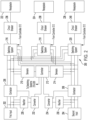
- FIG. 2 illustrates a block diagram of an automatic transfer switch 200 ("ATS 200") according to an example.
- the ATS 200 may be an example of the ATS 106 of FIG. 1 .
- the ATS 200 is configured to dynamically and/or selectively determine the phase and source of power provided at a given receptacle, each of which may be coupled to a respective one of the n loads.
- the ATS 200 includes a first input 202, a second input 204, a first contactor 206, a second contactor 208, one or more first sensors 210 ("first sensor 210"), at least one controller 212 ("controller 212"), one or more second sensors 214 ("second sensor 214"), a first switching system 216, a second switching system 218, a third switching system 220, a first receptacle 222, a second receptacle 224, a third receptacle 226, a first rectifier 228, a second rectifier 230, a first converter 232, a second converter 234, a first circuit breaker 236, a second circuit breaker 238, and a third circuit breaker 240.
- the ATS 200 is configured to receive power from three-phase power sources. Other examples may be configured to receive any number of phases of power.
- the first input 202 is coupled to the first contactor 206 and to the first rectifier 228.
- the first input 202 may be configured to receive three phases of first power.
- a first-phase first-power (that is, a first phase of first power) connection (or “first phase input”) of the first input 202 may be coupled to a respective connection of the first contactor 206 and of the first rectifier 228,
- a second-phase first-power connection (or "second phase input") of the first input 202 may be coupled to a respective connection of the first contactor 206 and of the first rectifier 228, and
- a third-phase first-power connection (or "third phase input") of the first input 202 may be coupled to a respective connection of the first contactor 206 and of the first rectifier 228.
- the second input 204 is coupled to the second contactor 208 and to the second rectifier 230.
- the second input 204 may be configured to receive three phases of second power.
- a first-phase second-power (that is, a first phase of second power) connection (or "fourth phase input") of the second input 204 may be coupled to a respective connection of the second contactor 208 and of the second rectifier 230
- a second-phase second-power connection (or "fifth phase input") of the second input 204 may be coupled to a respective connection of the second contactor 208 and of the second rectifier 230
- a third-phase second-power connection (or "sixth phase input”) of the second input 204 may be coupled to a respective connection of the second contactor 208 and of the second rectifier 230.
- the first contactor 206 is coupled to the first switching system 216, the second switching system 218, the third switching system 220, and the first converter 232.
- the first contactor 206 may have connections for providing the first, second, and third phases of first power to the switching systems.
- a first-phase first-power connection of the first contactor 206 may be coupled to a respective connection of the first switching system 216, a respective connection of the second switching system 218, and a respective connection of the third switching system 220.
- a second-phase first-power connection of the first contactor 206 may be coupled to a respective connection of the first switching system 216, a respective connection of the second switching system 218, and a respective connection of the third switching system 220.
- a third-phase first-power connection of the first contactor 206 may be coupled to a respective connection of the first switching system 216, a respective connection of the second switching system 218, and a respective connection of the third switching system 220.
- the first contactor 206 may be energized by the first converter 232, which dictates the switching state (for example, open and non-conducting if the first contactor 206 is not energized or closed and conducting if the first contactor 206 is energized) of the first contactor 206.
- the second contactor 208 is coupled to the first switching system 216, the second switching system 218, the third switching system 220, and the second converter 234.
- the second contactor 208 may have connections for providing the first, second, and third phases of second power to the switching systems.
- a first-phase second-power connection of the second contactor 208 may be coupled to a respective connection of the first switching system 216, a respective connection of the second switching system 218, and a respective connection of the third switching system 220.
- a second-phase second-power connection of the second contactor 208 may be coupled to a respective connection of the first switching system 216, a respective connection of the second switching system 218, and a respective connection of the third switching system 220.
- a third-phase second-power connection of the second contactor 208 may be coupled to a respective connection of the first switching system 216, a respective connection of the second switching system 218, and a respective connection of the third switching system 220.
- the second contactor 208 may be energized by the second converter 234, which dictates the switching state (for example, open and non-conducting if the second contactor 208 is not energized or closed and conducting if the second contactor 208 is energized) of the second contactor 208.
- the first sensor 210 may be coupled to one or more connections between the first contactor 206 and the first switching system 216, the second switching system 218, and/or the third switching system 220.
- the first sensor 210 may include a first sensor (for example, a current sensor) coupled in series between the first contactor 206 and the first switching system 216, a second sensor coupled in series between the first contactor 206 and the second switching system 218, and/or a third sensor coupled in series between the first contactor 206 and the third switching system 220.
- the first sensor 210 may include one or more sensors (for example, voltage sensors) coupled to at least one of a connection between the first contactor 206 and the first switching system 216, a connection between the first contactor 206 and the second switching system 218, and/or a connection between the first contactor 206 and the third switching system 220.
- the first sensor 210 is also coupled to the controller 212.
- the second sensor 214 may be coupled to one or more connections between the second contactor 208 and the first switching system 216, the second switching system 218, and/or the third switching system 220.
- the second sensor 214 may include a first sensor (for example, a current sensor) coupled in series between the second contactor 208 and the first switching system 216, a second sensor coupled in series between the second contactor 208 and the second switching system 218, and/or a third sensor coupled in series between the second contactor 208 and the third switching system 220.
- the second sensor 214 may include one or more sensors (for example, voltage sensors) coupled to at least one of a connection between the second contactor 208 and the first switching system 216, a connection between the second contactor 208 and the second switching system 218, and/or a connection between the second contactor 208 and the third switching system 220.
- the second sensor 214 is also coupled to the controller 212.
- the first switching system 216 is coupled to the first contactor 206 and the second contactor 208.
- the first switching system 216 has three independent connections to the first contactor 206 (one for each phase of first power), and three independent connections to the second contactor 208 (one for each phase of second power).
- the first switching system 216 is also coupled to the first receptacle 222 via the first circuit breaker 236.
- the second switching system 218 is coupled to the first contactor 206 and the second contactor 208.
- the second switching system 218 has three independent connections to the first contactor 206 (one for each phase of first power), and three independent connections to the second contactor 208 (one for each phase of second power).
- the second switching system 218 is also coupled to the second receptacle 224 via the second circuit breaker 238.
- the third switching system 220 is coupled to the first contactor 206 and the second contactor 208.
- the third switching system 220 has three independent connections to the first contactor 206 (one for each phase of first-power), and three independent connections to the second contactor 208 (one for each phase of second-power).
- the third switching system 220 is also coupled to the third receptacle 226 via the third circuit breaker 240.
- the first rectifier 228 is coupled to, and is configured to receive power from, the first input 202 at a plurality of input connections.
- the first rectifier 228 is also coupled to the first converter 232 at an output connection.
- the first rectifier 228 may be configured to receive one or more phases of AC power from the first input 202, to rectify the AC power, and to provide a single rectified DC output to the first converter 232. If power is not available from at least one phase at the first input 202, then the first rectifier 228 may not provide power to the first converter 232. If power is available from at least one phase at the first input 202, then in some examples the first rectifier 228 may provide rectified output power to the first converter 232 even if one or more other phases of power are not available at the first input 202.
- the second rectifier 230 is coupled to, and is configured to receive power from, the second input 204 at a plurality of input connections.
- the second rectifier 230 is also coupled to the second converter 234 at an output connection.
- the second rectifier 230 may be configured to receive one or more phases of AC power from the second input 204, to rectify the AC power, and to provide a single rectified DC output to the second converter 234. If power is not available from at least one phase at the second input 204, then the second rectifier 230 may not provide power to the second converter 234. If power is available from at least one phase at the second input 204, then in some examples the second rectifier 230 may provide rectified output power to the second converter 234 even if one or more other phases of power are not available at the second input 204.
- the first converter 232 is coupled to the first rectifier 228 at an input, and is coupled to the first contactor 206 and the controller 212 at respective outputs.
- the first converter 232 receives power from the first rectifier 228, converts the received power, and provides converted power to the first contactor 206 and the controller 212.
- the first converter 232 may be a DC/DC converter configured to adjust a voltage level of the received power.
- the power provided from the first converter 232 to the first contactor 206 energizes the first contactor 206 and causes the first contactor 206 to close and conduct. If the first converter 232 does not energize the first contactor 206 (for example, because power is unavailable from the first input 202), then the first contactor 206 remains open and non-conducting.
- the second converter 234 is coupled to the second rectifier 230 at an input, and is coupled to the second contactor 208 and the controller 212 at respective outputs.
- the second converter 234 receives power from the second rectifier 230, converts the received power, and provides converted power to the second contactor 208 and the controller 212.
- the second converter 234 may be a DC/DC converter configured to adjust a voltage level of the received power.
- the power provided from the second converter 234 to the second contactor 208 energizes the second contactor 208 and causes the second contactor 208 to close and conduct. If the second converter 234 does not energize the second contactor 208 (for example, because power is unavailable from the second input 204), then the second contactor 208 remains open and non-conducting.
- the contactors 206, 208 in combination with the rectifiers 228, 230 and the converters 232, 234, prevent backfeed when the inputs 202, 204 are not energized by power sources.
- the contactors 206, 208 are open and non-conducting (and thus isolate the inputs 202, 204 from the remainder of the ATS 200) unless power is available at the inputs 202, 204 to energize the contactors 206, 208.
- the contactors 206, 208 may be closed and conducting.
- the contactors 206, 208 are open and non-conducting.
- the open contactors 206, 208 isolate the inputs 202, 204 from the rest of the ATS 200. This isolation may prevent backfeed to the inputs 202, 204 from other parts of the ATS 200.
- the first input 202 is configured to receive three phases of first power. That is, the first input 202 is configured to be coupled to a first power source (for example, the first power source 102) configured to provide three phases of first power. The first input 202 is configured to provide each phase of first power to the first contactor 206.
- a first power source for example, the first power source 102
- the first input 202 is configured to provide each phase of first power to the first contactor 206.
- the second input 204 is configured to receive three phases of second power. That is, the second input 204 is configured to be coupled to a second power source (for example, the second power source 104) configured to provide three phases of second power. The second input 204 is configured to provide each phase of second power to the second contactor 208.
- a second power source for example, the second power source 104
- the second input 204 is configured to provide each phase of second power to the second contactor 208.
- the first contactor 206 is configured to receive the phases of first power from the first input 202, and relay those phases of power to the first switching system 216, the second switching system 218, and/or the third switching system 220.
- the first contactor 206 may also operate as a switching device (for example, a relay, dip-switch, limit switch, transistor-based switch, and so forth) to control whether any or all phases of first power are provided to the switching systems, including the first switching system 216, the second switching system 218, and/or the third switching system 220.
- the first contactor 206 could stop providing the first phase of the first power to the rest of a system (for example, the first switching system 216, the second switching system 218, and/or the third switching system 220, and the first sensor 210).
- the first contactor 206 may stop providing those additional phases of power to a system as well.
- the first contactor 206 may stop providing any phases of the first power from the rest of the ATS 200.
- the second contactor 208 is configured to receive the phases of second power from the second input 204, and relay those phases of power to the first switching system 216, the second switching system 218, and/or the third switching system 220.
- the second contactor 208 may also operate as a switching device (for example, a relay, dip-switch, limit switch, transistor-based switch, and so forth) to control whether any or all phases of second power are provided to the switching systems, including the first switching system 216, the second switching system 218, and/or the third switching system 220.
- the second contactor 208 could stop providing the first phase of second power to the rest of the system (for example, to the first switching system 216, the second switching system 218, the third switching system 220, and/or and the second sensor 214).
- the second contactor 208 could stop providing those additional phases to the system as well.
- the second contactor 208 may stop providing any phases of the second power from the rest of the ATS 200.
- the first sensor 210 is configured to sense one or more characteristics of the phases of the first power. Characteristics of power may generally include voltage, current, phase, frequency, period, harmonic content, and so forth.
- the first sensor 210 may include more than one sensor, and/or may include multiple sensor connections. Thus, the first sensor 210 may independently monitor the first phase of first power, the second phase of the first power, and/or the third phase of the first power, and may include multiple (for example, three) sensors to perform the monitoring.
- the second sensor 214 is configured to sense one or more characteristics of the phases of the second power. Characteristics of power may generally include voltage, current, phase, frequency, period, harmonic content, and so forth.
- the second sensor 214 may include more than one sensor, and/or may include multiple sensor connections. Thus, the second sensor 214 may independently monitor the first phase of second power, the second phase of the second power, and/or the third phase of the second power, and may include multiple (for example, three) sensors to perform the monitoring.
- first switching system 216, the second switching system 218, and/or the third switching system 220 are each configured to select between phases of power and sources of power.
- Each of the first switching system 216, the second switching system 218, and/or the third switching system 220 is configured to provide output power to a respective receptacle.
- the first switching system 216 is configured to provide first output power to the first receptacle 222 via the first circuit breaker 236.
- the second switching system 218 is configured to provide second output power to the second receptacle 224 via the second circuit breaker 238.
- the third switching system 220 is configured to provide third output power to the third receptacle 226 via the third circuit breaker 240.
- the first output power, second output power, and third output power may each be single-phase power.
- Each of the circuit breakers 236-240 may trip (that is, transition from being closed and conducting to being open and non-conducting) if a current conducted by the respective circuit breaker exceeds a current rating. For example, if the current through the first circuit breaker 236 exceeds the current rating of the first circuit breaker 236, then the first circuit breaker 236 may trip and thereby disconnect the first switching system 216 from the first receptacle 222.
- Each of the first switching system 216, the second switching system 218, and/or the third switching system 220 may be configured to provide a single phase of first power or a single phase of second power to a respective one of the first receptacle 222, second receptacle 224, and/or third receptacle 226.
- the first switching system 216 may be configured to provide the first phase of the first power or the first phase of the second power, the second phase of the first power or the second phase of the second power, or the third phase of the first power or the third phase of the second power to the first receptacle 222.
- the second switching system 218 may be configured to provide the first phase of the first power or the first phase of the second power, the second phase of the first power or the second phase of the second power, or the third phase of the first power or the third phase of the second power to the second receptacle 224.
- the third switching system 220 may be configured to provide the first phase of the first power or the first phase of the second power, the second phase of the first power or the second phase of the second power, or the third phase of the first power or the third phase of the second power to the third receptacle 226. More generally, each of the first switching system 216, the second switching system 218, and/or the third switching system 220 may freely and independently output any given phase of the first power or the second power. Accordingly, each of the first receptacle 222, second receptacle 224, and/or third receptacle 226 may receive output power derived from a different phase or different source compared to any other receptacle.
- each of the first switching system 216, the second switching system 218, and/or the third switching system 220 may output, to a respective one of the first receptacle 222, second receptacle 224, and/or third receptacle 226, power from the same source but with a different phase.
- the first switching system 216 may provide a first phase of the first power to the first receptacle 222; the second switching system 218 may provide a second phase of the first power to the second receptacle 224; and the third switching system 220 may provide a third phase of the first power to the third receptacle 226.
- the first switching system 216 may provide a first phase of the second power to the first receptacle 222; the second switching system 218 may provide a second phase of the second power to the second receptacle 224; and the third switching system 220 may provide a third phase of the second power to the third receptacle 226.
- the first switching system 216 may provide a second phase of the first power to the first receptacle 222; the second switching system 218 may provide a third phase of the first power to the second receptacle 224; and the third switching system 220 may provide a first phase of the first power to the third receptacle 226.
- the first switching system 216, the second switching system 218, and/or the third switching system 220 will be discussed in further detail with respect to FIG. 4 .
- the first receptacle 222 is configured to provide first output power to a first load connected to the first receptacle 222 (for example, the first load 108).
- the second receptacle 224 is configured to provide second output power to a second load.
- the third receptacle 226 is configured to provide third output power to a third load.
- the receptacles may include, for example, electrical outlets configured to provide power to a connected load.
- the controller 212 is configured to control the first switching system 216, the second switching system 218, and/or the third switching system 220, the first contactor 206 and/or second contactor 208, and/or the first sensor 210 and/or second sensor 214.
- the controller 212 may also be configured to communicate with loads and/or power sources (for example, the first power source 102, second power source 104, and/or any of the n loads including the first load 108 and/or nth load 110).
- the controller 212 may determine whether the first contactor 206 and/or second contactor 208 should be in an open state or a closed state and control the first contactor 206 and/or second contactor 208 accordingly.
- the controller 212 may further determine a desired power source and power phase to provide to the first receptacle 222, second receptacle 224, and/or third receptacle 226, and may control the first switching system 216, the second switching system 218, and/or the third switching system 220 accordingly.
- the ATS 200 generally operates as follows. Power may be received at the inputs 202, 204 from the power sources 102, 104, respectively. If power is available at the inputs 202, 204, then the contactors 206, 208 are energized by the power received at the inputs 202, 204. The contactors 206, 208 close in response to being energized and provide power to the switching systems 216-220. If power is not available at one of the inputs 202, 204, then the corresponding one of the contactors 206, 208, respectively, is not energized and remains open. For example, if acceptable power is not available at the first input 202, then the first contactor 206 remains open.
- Each of the switching systems 216-220 receives power from one or both of the contactors 206, 208. Each switching system 216-220 selects one of the inputs 202, 204 to draw power from. If power is only available from one of the inputs 202, 204, then the switching systems 216-220 draw power only from that input. If power is available from both of the inputs 202, 204, then the switching systems 216-220 may default to drawing power from a preferred one of the inputs 202, 204. Either of the inputs 202, 204 may be arbitrarily selected as a preferred input. For example, the first input 202 may arbitrarily be selected as a preferred input.
- the switching systems 216-220 preferably draw power from the first input 202 if power is available from both of the inputs 202, 204.
- the controller 212 may control the switching systems 216-220 to switch to drawing power from the second input 204 if acceptable power is no longer available at the first input 202.
- the selected power source may provide multiple phases of power.
- the controller 212 may decide which phase of power is to be provided to the receptacles 222-226. For example, if the first input 202 provides three-phase power with phases Lla, L2a, and L3a, then the controller 212 may control each of the switching systems 216-220 to provide a selected one of these three phases to a respective receptacle. Each of the switching systems 216-220 may provide the same or a different phase of power to a respective one of the receptacles 222-226.
- the first switching system 216 may provide phase L1a to the first receptacle 222
- the second switching system 218 may provide phase L2a to the second receptacle 224
- the third switching system 220 may provide phase L3a to the third receptacle 226.
- the controller 212 may control the switching systems 216-220 to route any phase of power from any power source to any one of the receptacles 222-226.
- the controller 212 may control the switching systems 216-220 to switch power sources if, for example, a selected power source is no longer able to provide acceptable power.
- the controller 212 may control the switching systems 216-220 to switch which phase of power is provided to the receptacles 222-226 to, for example, balance the load across the phases.
- the ATS 200 may therefore provide redundant three-to-single-phase power while dynamically balancing power drawn across multiple phases.
- FIG. 3 illustrates a process 300 for determining the source and phase of power to provide to a load according to an example.
- the loads may include loads coupled to the receptacles 222-226.
- the source of the power may be switched from one power supply to another.
- the source of power may be switched from the first input 202 (which may be coupled to the first power source 102) to the second input 204 (which may be coupled to the second power source 104).
- the phase of power provided to the load may be adjusted, for example, to maintain a balanced distribution of loads across numerous phases of power.
- the phase of power may be adjusted from a first of three phases of three-phase power received at the first input 202 to a second of three phases of three-phase power received at the first input 202.
- the process 300 is described as beginning after the controller 212 has determined which phases of power to provide to respective loads, and the ATS 200 is providing those respective phases of power to the respective loads.
- the controller 212 may thus have controlled or be controlling the switching systems 216-220 to establish desired source-to-load conductive paths from the first input 202 and/or the second input 204 to the receptacles 222-226.
- the inputs 202, 204 receive power from the power sources 102, 104, respectively.
- the contactors 206, 208 may close responsive to being energized by the power sources 102, 104. Power is therefore provided from the inputs 202, 204 to the switching systems 216-220 via the contactors 206, 208.
- the controller 212 monitors power characteristics of the power provided by the first power source 102 and/or the second power source 104 to the receptacles 222-226.
- the controller 212 may receive power-characteristic information indicative of the power characteristics (for example, a voltage, a current, and so forth) from the sensors 210, 214.
- act 302 is executed after the controller 212 has previously determined which phases of power to provide to which of the receptacles 222-226, the controller 212 may be capable of correlating the power-characteristic information to each source-to-receptacle connection. For example, the controller 212 may be capable of determining the source and phase of the power provided to each of the receptacles 222-226 and may have access to power-characteristic information for each.
- the process 300 may continue to act 304.
- the controller 212 determines whether to change the power source providing power to one or more of the loads. For example, the controller 212 may determine whether the power quality provided to at least one load ("the loads") is acceptable for the load. The controller 212 may determine whether the power quality is acceptable for the loads based on one or more criteria. For example, the controller 212 may determine whether the characteristics of the power (for example, voltage, current, phase, frequency, period, harmonic content, and so forth) determined at act 302 fall within a certain range or ranges of values. As an example, suppose the loads requires power provided at 50 A of current, with a tolerance of +/- 1 A.
- the power quality may be acceptable if the current of the power is within a range of 49 to 51 A, but may not be acceptable if the power is provided outside that range. Characteristics may be required (to be considered acceptable) to fall within a given range, or to be above or below a threshold value.
- the controller 212 may determine, in addition or alternatively to determining whether the characteristics of the power are acceptable, whether one power source is under undue strain.
- Undue strain may include the difference in power provided by one power source compared to another exceeding a threshold percentage or magnitude.
- a power source such as the first power source 102
- Act 304 may therefore include the controller 212 determining whether the difference in power provided by the power sources 102, 104 exceeds a threshold amount (such as a threshold amount of power or a threshold difference in power) or falls outside a target range).
- the controller 212 may determine whether the power provided by a power source is acceptable based on the characteristics of the power, the distribution of power consumption between the power sources (such as the power sources 102, 104), the number of loads drawing power from the power sources, and/or so forth. That is, the controller 212 may transfer a given load to a given power source based on the power quality, and/or to more evenly distribute the number of loads across the power sources, and/or to more evenly distribute the power consumption of loads across the power sources, and so forth. In various examples, the controller 212 may not switch every load of the loads to a new power source.
- the controller 212 may allow some of the one or more loads of the loads to continue receiving power from the original power source, for example, because the power quality improves, the power sources become balanced, or the strain is alleviated (for example, by the transfer of other loads to the other power sources).
- the process 300 may continue to act 308. If the controller 212 determines that the power quality is not acceptable (304 NO), the process 300 may continue to act 306.
- the controller 212 may control a respective switching system (for example, the switching systems 216-220) to change a power source that is providing power to one or more respective loads.
- the controller 212 may transfer the one or more loads from a first power source (for example, the first power source 102) to a second power source (for example, the second power source 104).
- the controller 212 may control a switching system (for example, the first switching system 216) to change from one power source to another by controlling a phase-selection interface of the switching system to switch from drawing power from a power source and/or input to a different power source and/or input.
- the process 300 may return to act 302.
- the process 300 may then return to act 304. If the controller 212 determines at act 304 that a power source is not to be changed (304 YES), then the process 300 continues to act 308.
- the controller 212 determines whether to change the phase of power provided to the loads.
- the controller 212 may determine whether the one or more phases of the power provided to the loads are acceptable for the load, and may determine to change the phase of power provided to a given load based on that phase of power being acceptable or not. As with act 304, numerous parameters may be employed to make this determination.
- the controller 212 may determine whether to change the phase of power provided to one or more loads of the loads based on one or more phase-change criteria.
- the controller 212 may determine that the characteristics of the power fall outside a desired range or exceed (or fall below) a given threshold (for example, a current, voltage frequency, or voltage magnitude threshold and/or range). Such a determination may include, for example, the controller 212 determining whether the voltage, frequency, and/or current fall outside of an acceptable range.
- the controller 212 may also determine whether a given phase of power is under undue strain. A given phase of power may be under undue strain if the difference in power provided by that phase of power compared to another phase of power (for example, from the same power source) exceeds a threshold amount or falls outside of a desired range.
- the process 300 may continue to act 302.
- returning to act 302 from act 308 may indicate that-at least for the time being-the power source and the phases of power are providing power effectively, such as by having acceptable power characteristics, being evenly distributed, and/or not being under undue strain.
- the process 300 continues to act 310.
- continuing to act 310 may indicate that it may be desirable to change the phase of power provided to at least one load because, for example, power is not evenly distributed between the phases of a power source.
- the controller 212 may not switch every load of the loads to a new phase of power.
- the controller 212 may allow some of the one or more loads of the loads to continue receiving the original phase of power, for example, because the power quality improves, the phases become balanced, or the strain is alleviated (for example, by the transfer of other loads to the other phases of power).
- the controller 212 may determine which phase of power to switch to based on the characteristics of that phase of power, the distribution of power consumption between loads, the number of loads drawing power from a given phase of power, and/or so forth. That is, the controller 212 may transfer a given load to a given phase of power based on the power quality, and/or to more evenly distribute the number of loads across the phases of power, and/or to more evenly distribute the power consumption of loads across the phases of power (that is, reduce undue strain), and/or so forth.
- the controller 212 controls a phase-selection interface of a switching device to transition one or more loads of the loads from a first phase of power to a different phase of power provided by the same power source as provided the first phase of power.
- the controller 212 may control a phase-selection interface to switch from providing a first phase of power to providing a second phase of power.
- the process 300 may continue to act 302.
- FIG. 4 illustrates a switching system 400 coupled to a receptacle 414 according to an example.
- the switching system 400 may be one example of an implementation of any of the switching systems 216-220, and the receptacle 414 may be an example of any of the receptacles 222-226.
- a controller such as the controller 212, may control the switching system 400 to dynamically and selectively change which power source and which power phase is provided to a load coupled to the receptacle 414, thus allowing the switching system 400 to control the exact phase and source of the power provided at to the receptacle 414.
- the switching system 400 includes a phase-selection interface 402 and a switching device 408.
- the phase-selection interface 402 includes a first phase selector 404 and a second phase selector 406.
- the switching device 408 includes a first switch 410 and a second switch 412.
- the first switch 410 includes a first power switch 410a and a first ground switch 410b.
- the second switch 412 includes a second power switch 412a and a second ground switch 412b.
- the switching system 400 also includes a reference-voltage connection 416 ("reference connection 416"), which may be coupled to a reference-voltage node, such as a neutral node.
- the phase-selection interface 402 is coupled to the switching device 408.
- the switching device 408 is coupled to the phase-selection interface 402 and is coupled to the receptacle 414.
- the reference connection 416 is coupled to the switching device 408.
- the first phase selector 404 is coupled to the switching device 408 at a first terminal of the first power switch 410a of the first switch 410.
- the second phase selector 406 is coupled to the switching device 408 at a first terminal of the second power switch 412a of the second switch 412.
- the reference connection 416 is coupled to the switching device 408 at a first terminal of the first ground switch 410b of the first switch 410 and at a first terminal of the second ground switch 412b of the second switch 412.
- the receptacle 414 may have a first connection and a second connection.
- the first connection of the receptacle 414 may be coupled to the switching device 408 at a second terminal of the first power switch 410a of the first switch 410 and at a second terminal of the second power switch 412a of the second switch 412.
- the second connection of the receptacle 414 may be coupled to the switching device 408 at a second terminal of the first ground switch 410b of the first switch 410 and at a second terminal of the second ground switch 412b of the second switch 412.
- the phase-selection interface 402 is configured to receive one or more phases of power from the first power source 102 and one or more phases of power from the second power source 104. In some examples, the phase-selection interface 402 may receive all available phases of power from both power sources 102, 104. In FIG. 4 , the phases of power received from the first power source 102 are labeled A, B, and C, and the phases of power received from the second power source 104 are labeled D, E, and F.
- the first phase selector 404 is configured to receive the A, B, and C phases of first power from the first power source 102
- the second phase selector 406 is configured to receive the D, E, and F phases of second power from the second power source 104.
- the first phase selector 404 has a single output (connected to the switching device 408 at the first terminal of the first power switch 410a).
- the first phase selector 404 is configured to route one of the A, B, and C phases of first power to the switching device 408 (for example, at the first power switch 410a) via the output.
- the second phase selector 406 also has a single output (connected to the switching device 408 at the first terminal of the second power switch 412a).
- the second phase selector 406 is configured to route one of the D, E, and F phases of the second power to the switching device 408 (for example, to the second power switch 412a) via the output.
- the first phase selector 404 and the second phase selector 406 may have switching, routing, or other control systems internally to selectively route a given phase of power to the switching device 408 while blocking the other phases of power.
- the switching device 408 is configured to select between power derived from the first power source 102 and power derived from the second power source 104 to provide to the receptacle 414.
- the switching device 408 may receive a phase of the first power and a phase of the second power simultaneously, and may route one of those phases to the receptacle 414. For example, if the switching device 408 receives the A phase of power from the first phase selector 404 and the D phase of power from the second phase selector 406, the switching device 408 may route either the A phase of power or the D phase of power to the receptacle 414.
- the first switch 410 controls the connection between the first power source 102 and the receptacle 414, and the second switch 412 control the connection between the second power source 104 and the receptacle 414.
- the first power switch 410a controls whether the output of the first phase selector 404 is coupled to the receptacle 414.
- the first power switch 410a is closed and conducting, the output of the first phase selector 404 is coupled to the receptacle 414.
- the first power switch 410a is open and non-conducting, the output of the first phase selector 404 is decoupled from the receptacle 414.
- the second power switch 412a controls when the output of the second phase selector 406 is coupled to the receptacle 4143. When the second power switch 412a is closed and conducting, the output of the second phase selector 406 is coupled to the receptacle 414. When the second power switch 412a is open and non-conducting, the output of the second phase selector 406 is decoupled from the receptacle 414.
- Both the first switch 410 and the second switch 412 contain respective reference-node switches (the first reference-node switch 410b and the second reference-node switch 412b). When either reference-node switch is closed, the receptacle 414 is coupled to the reference connection 416.
- the first power switch 410a and first ground switch 410b may be operated in tandem, such that when one is closed the other is also closed, and when one is open the other is also open.
- the second power switch 412a and second ground switch 412b may be operated in tandem, such that when one is closed the other is also closed, and when one is open the other is also open.
- the first switch 410 and second switch 412 may be operated in complementary fashion such that when one is open (and not conducting) the other is closed (and conducting). For example, when the first switch 410 is open the second switch 412 is closed, and when the first switch 410 is closed the second switch 412 is open. In some examples, the first switch 410 and second switch 412 may both be open at the same time.
- FIG. 5A illustrates a phase-selection interface 502 according to an example.
- the phase-selection interface 502 has only a single phase selector 504.
- the phase selector 504 is configured to receive each of the A, B, C, D, E, and F phases of the first power source 102 and the second power source 104.
- the phase selector 504 is configured to provide one phase of power from among the A, B, C, D, E, and F phases of power at a first output (for example, the "X" output) and one phase of the A, B, C, D, E, and F phases of power at the second output (for example, the "Y" output).
- a first output for example, the "X” output
- the A, B, and C phases of power may be provided by a first power source
- the D, E, and F phases of power may be provided by a second power source.
- FIG. 5B illustrates a phase-selection interface 552 according to another example.
- the phase-selection interface 522 has one phase selector for each phase of power (including a first phase selector 554, a second phase selector 556, and a third phase selector 558).
- Each of the phase selectors 554-558 is configured to receive a single phase of first power or a single phase of second power.
- the first phase selector 554 is configured to receive the A-phase of the first power
- the second phase selector 556 is configured to receive the B-phase of the first power
- the third phase selector 558 is configured to receive the F-phase of the second power.
- Each phase selector of the phase-selection interface 552 may control whether the phase of received power is available to an output (the "X" and/or "Y" outputs) of the phase-selection interface 552.
- one of the A, B, or C phase of first power may be provided at the X output
- one of the D, E, or F phases of second power may be provided at the Y output.
- phase-selection interface 402 may include the phase selectors 404 and 406 of FIG. 4 , the phase selector 504 of FIG. 5A , the phase selectors 554-558 of FIG. 5B , or may include some other configuration of phase selectors.
- FIG. 6 illustrates a block diagram of a phase selection topology 600 according to an example.
- the topology 600 includes a phase-selection interface 602, a first switching device 604, a second switching device 606, a third switching device 608, a first receptacle 610, a second receptacle 612, and a third receptacle 614.
- the phase selection for all of the switching devices 604-608 is handled at the phase-selection interface 602, which provides a respective phase of first power and a respective phase of second power to each of the switching devices 604-608.
- the phase-selection interface 602 is coupled to the first switching device 604 via a first connection, is coupled to the second switching device 606 via a second connection, and is coupled to the third switching device 608 via a third connection.
- the first switching device 604 is coupled to the phase-selection interface 602 at a first connection and is coupled to the first receptacle 610 at a second connection.
- the second switching device 606 is coupled to the phase-selection interface 602 at a first connection and is coupled to the second receptacle 612 at a second connection.
- the third switching device 608 is coupled to the phase-selection interface 602 at a first connection and is coupled to the third receptacle 614 at a second connection.
- the phase-selection interface 602 is configured to receive each phase of first power and each phase of second power. The phase-selection interface 602 then provides a first phase of first power and a first phase of second power to the first switching device 604, a second phase of first power and a second phase of second power to the second switching device 606, and a third phase of first power and a third phase of second power to the third switching device 608.
- the first, second, and third phases of first power and second power may be the same phase or different phases.
- the first switching device 604 routes the first phase of first power or the first phase of second power to the first receptacle 610.
- the second switching device 606 routes the second phase of first power or the second phase of the second power to the second receptacle 612.
- the third switching device 608 routes the third phase of first power or the third phase of second power to the third receptacle 614.
- the phase-selection interface 602 may provide both the A phase of first power and the D phase of second power to the first switching device 604.
- the first switching device 604 may then provide one of either the A phase of first power or the D phase of second power to the first receptacle 610.
- the first receptacle 610 provides the phase of power received from the first switching device 604 to a load.
- the second receptacle 612 provides the phase of power received from the second switching device 606 to a load.
- the third receptacle 614 provides the phase of power received from the third switching device 608 to a load.
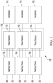
- FIG. 7 illustrates a block diagram of a plurality of switching systems 700 ("switching system 700") according to an example.
- the switching system 700 may be one example of an implementation of any and/or all of the switching systems 216-220.
- the switching system 700 includes a first switching device 702, a second switching device 704, a third switching device 706, a phase-selection interface 708, a first receptacle 716, a second receptacle 718, and a third receptacle 720.
- the phase-selection interface 708 includes a first phase selector 710, a second phase selector 712, and a third phase selector 714.
- the first switching device 702 is coupled to the first phase selector 710.
- the first switching device 702 may be coupled to the first phase selector 710 via a first connection, a second connection, and a third connection, where each connection carries a different phase of either the first power or the second power.
- the second switching device 704 is coupled to the second phase selector 712.
- the second switching device 704 may be coupled to the second phase selector 712 via a first connection, a second connection, and a third connection, where each connection carries a different phase of either the first power or the second power.
- the third switching device 706 is coupled to the third phase selector 714.
- the third switching device 706 may be coupled to the third phase selector 714 via a first connection, a second connection, and a third connection, where each connection carries a different phase of either the first power or the second power.
- the first phase selector 710 is further coupled to the first receptacle 716.
- the second phase selector 712 is further coupled to the second receptacle 718, and the third phase selector 714 is further coupled to the third receptacle 720.
- the first switching device 702 is configured to receive each phase of the first power (phases A, B, and C) and each phase of the second power (phases D, E, and F). The first switching device 702 selects between the phases of the first power and the phases of the second power, and provides either the phases A, B, and C of the first power to the first phase selector 710, or provides the phases D, E, and F of the second power to the first phase selector 710.
- the second switching device 704 is configured to receive each phase of the first power (phases A, B, and C) and each phase of the second power (phases D, E, and F). The second switching device 704 selects between the phases of the first power and the phases of the second power, and provides either the phases A, B, and C of the first power to the second phase selector 712, or provides the phases D, E, and F of the second power to the second phase selector 712.
- the third switching device 706 is configured to receive each phase of the first power (phases A, B, and C) and each phase of the second power (phases D, E, and F). The third switching device 706 selects between the phases of the first power and the phases of the second power, and provides either the phases A, B, and C of the first power to the third phase selector 714, or provides the phases D, E, and F of the second power to the third phase selector 714.
- the first phase selector 710 selects one phase from among the phases provided to the first phase selector 710 and provides the chosen phase to the first receptacle 716.
- the second phase selector 712 selects one phase from among the phases provided to the second phase selector 712 and provides the chosen phase to the second receptacle 718.
- the third phase selector 714 selects one phase from among the phases provided to the third phase selector 714 and provides the chosen phase to the third receptacle 720.
- the switching system 700 may be similar to the switching system 400.
- each of the switching systems 400, 700 may enable a desired phase of power from a desired power source to be provided to a respective receptacle.
- the receptacle 414 is coupled to the switching device 408, in FIG. 7 the first receptacle 716, for example, is coupled to the first phase selector 710 of the phase-selection interface 708. That is, whereas in FIG. 4 the phase-selection interface 402 is upstream of the switching device 408, in FIG. 7 the first switching device 702 is upstream of the phase-selection interface 708.
- various examples of the switching systems 216-220 are within the scope of the disclosure, and an order of components may be rearranged between different examples.
- FIG. 8A illustrates a schematic diagram of a first switching topology 800 according to an example.
- the first switching topology 800 may represent an implementation of any of various phase-selection interfaces, phase selectors, and/or switching devices discussed herein.
- the first switching topology 800 may represent an example implementation of either of the phase selectors 404, 406, or any of the phase selectors 710-714.
- the first switching topology 800 includes a first phase-selection switch 802 ("first switch 802"), a second phase-selection switch 804 ("second switch 804"), a third phase-selection switch 806 ("third switch 806"), and an output 808.
- Each of the phase-selection switches 802-806 may be communicatively coupled to a controller, such as the controller 212.
- the first switch 802 may be configured to receive a first phase of power
- the second switch 804 may be configured to receive a second phase of power
- the third switch 806 may be configured to receive a third phase of power.
- the first switch 802 is closed, the first phase of power is provided to the output 808 via the conducting path created by the closed state of the first switch 802.
- the second switch 804 when the second switch 804 is closed, the second phase of power is provided to the output 808.
- the third switch 806 is closed, the third phase of power is provided to the output 808.
- the respective switch(es) does not provide power to the output 808.
- Each switch may be opened or closed independently. However, in some examples, when one switch is closed the other two switches are open. For example, if the first switch 802 is closed (such that the first phase of power is provided to the output 808), the second switch 804 and the third switch 806 may be open.
- FIG. 8B illustrates a schematic diagram of a second phase-selection switch topology 850 ("second switching topology 850") according to another example.
- the second switching topology 850 may represent an implementation of any of various phase-selection interfaces, phase selectors, and/or switching devices discussed herein.
- the second switching topology 850 may represent an example implementation of either of the phase selectors 404, 406, or any of the phase selectors 710-714.
- the second switching phase-selection switch topology 850 is an example of a single-pole triple-throw switch.
- the second switching topology 850 includes a first terminal 852, a second terminal 854, a third terminal 856, and a pole 858.
- the first terminal 852 may be configured to receive a first phase of power
- the second terminal 854 may be configured to receive a second phase of power
- the third terminal 856 may be configured to receive a third phase of power.
- the second switching topology 850 may be coupled to a controller (for example, the controller 212) configured to control a switching state of the second switching topology 850.
- the controller 212 may control the second switching topology 850 such that the pole 858 is coupled to one of the terminals 852-856.
- the second switching topology 850 may therefore perform a similar function as the first switching topology 800, albeit with a different structure.
- controllers such as the controller 212 may execute various operations discussed above. Using data stored in associated memory and/or storage, the controller 212 also executes one or more instructions stored on one or more non-transitory computer-readable media, which the controller 212 may include and/or be coupled to, that may result in manipulated data.
- the controller 212 may include one or more processors or other types of controllers.
- the controller 212 is or includes at least one processor.
- the controller 212 performs at least a portion of the operations discussed above using an application-specific integrated circuit tailored to perform particular operations in addition to, or in lieu of, a general-purpose processor.
- examples in accordance with the present disclosure may perform the operations described herein using many specific combinations of hardware and software and the disclosure is not limited to any particular combination of hardware and software components.
- Examples of the disclosure may include a computer-program product configured to execute methods, processes, and/or operations discussed above.
- the computer-program product may be, or include, one or more controllers and/or processors configured to execute instructions to perform methods, processes, and/or operations discussed above.
Landscapes
- Engineering & Computer Science (AREA)
- Power Engineering (AREA)
- Business, Economics & Management (AREA)
- Emergency Management (AREA)
- Supply And Distribution Of Alternating Current (AREA)
Abstract
Examples of the disclosure include an automatic transfer switching system comprising a first input to receive phases of first power from a first source, a second input to receive phases of second power from a second source, a receptacle, a phase-selection interface (PSI) configured to receive the first power and output a first selected phase and receive the second power and output a second selected phase, a switching device coupled to the receptacle and the PSI, and at least one controller configured to control the switching device to couple the first input to the receptacle via the PSI to provide the first selected phase when the switching device decouples the second input from the receptacle, and to control the switching device to couple the second input to the receptacle via the PSI to provide the second selected phase when the switching device decouples the first input from the receptacle.
Description
- At least one example in accordance with the present disclosure relates generally to power-transfer systems.
- Server racks in data centers may use large amounts of power. Some server racks may be connected to multiple main-power sources. If power becomes unavailable from one main-power source, the server rack may switch to drawing power from another main-power source.
- According to at least one aspect of the present disclosure, an automatic transfer switching (ATS) system is provided comprising a first input configured to receive multiple phases of first power from a first power source, a second input configured to receive multiple phases of second power from a second power source, a receptacle configured to provide power to one or more loads, at least one phase-selection interface configured to receive the multiple phases of first power from the first power source and selectively output a first selected phase of the first power chosen from among the multiple phases of the first power, and receive the multiple phases of second power from the second power source and selectively output a second selected phase of the second power chosen from among the multiple phases of the second power, at least one switching device coupled to the receptacle and to the at least one phase-selection interface, and at least one controller configured to control the at least one switching device to provide power to the receptacle, wherein controlling the at least one switching device to provide power to the receptacle includes controlling the at least one switching device to couple the first input to the receptacle via the at least one phase-selection interface to provide the first selected phase to the receptacle when the at least one switching device decouples the second input from the receptacle, and controlling the at least one switching device to couple the second input to the receptacle via the at least one phase-selection interface to provide the second selected phase to the receptacle when the at least one switching device decouples the first input from the receptacle.
- In at least one example, the at least one switching device includes a first switch and a second switch, the first switch being configured to selectively couple the receptacle to the first input and the second switch being configured to selectively couple the receptacle to the second input. In at least one example, the first switch is in a closed state when the first switch couples the first input to the receptacle, the second switch is in a closed state when the second switch couples the second input to the receptacle, the first switch is in an open state when the first switch decouples the first input from the receptacle, and the second switch is in an open state when the second switch decouples the second input from the receptacle.
- In at least one example, the at least one phase-selection interface includes a phase selection switch configured to selectively couple at least one phase input of the first input to the receptacle, the at least one phase input being configured to receive at least one phase of the multiple phases of first power from a power source. In at least one example, the at least one phase-selection interface includes a phase selection switch configured to selectively couple at least one phase input of the first input to the at least one switching device, the at least one phase input being configured to receive at least one phase of the multiple phases of first power from a power source. In at least one example, the at least one phase-selection interface includes a phase selection switch configured to selectively couple at least one phase input of the second input to the receptacle, the at least one phase input being configured to receive at least one phase of the multiple phases of second power from a power source.
- In at least one example, the at least one phase-selection interface includes a phase selection switch configured to selectively couple at least one phase input of the second input to the at least one switching device, the at least one phase input being configured to receive at least one phase of the multiple phases of second power. In at least one example, the at least one phase-selection interface is configured to switch from outputting the first selected phase of the first power to outputting a third selected phase of the first power, the third selected phase chosen from among the multiple phases of the first power. In at least one example, the at least one phase-selection interface is configured to switch from outputting the second selected phase of the second power to outputting a third selected phase of the second power, the third selected phase chosen from among the multiple phases of the second power.
- In at least one example, the ATS system includes a multiphase rectifier configured to receive power from one of the first input or the second input, and a converter coupled to the multiphase rectifier and configured to receive power from the multiphase rectifier, process power received from the multiphase rectifier into processed power, and provide the processed power to the at least one controller. In at least one example, a first total number of the multiple phases of first power equals a second total number of the multiple phases of second power, and the ATS system further comprises at least one respective receptacle for each respective phase of first power, and at least one respective switching device for each respective phase of first power.
- Aspects of the disclosure include a method of transferring power automatically using a switching system having a first input, a second input, at least one phase-selection interface, at least one switching device, and a receptacle, the method comprising receiving, at the first input, first power having multiple phases from a first power source, receiving, by the at least one phase-selection interface, the multiple phases of first power, selecting, by the at least one phase-selection interface, a first selected phase of first power from the multiple phases of first power, outputting, by the at least one phase-selection interface, the first selected phase of first power to the at least one switching device, receiving, at the second input, second power having multiple phases from a second power source, receiving, by the at least one phase-selection interface, the multiple phases of second power, selecting, by the at least one phase-selection interface, a second selected phase of second power from the multiple phases of second power, outputting, by the at least one phase-selection interface, the second selected phase of second power to the at least one switching device, receiving, by the at least one switching device, the first selected phase of first power and the second selected phase of second power, and providing, by the at least one switching device, one of the first selected phase of first power or the second selected phase of second power to the receptacle by coupling one of the first input or the second input to the receptacle while decoupling the other of the first input or the second input from the receptacle.
- In at least one example, the method includes providing, by the at least one switching device, the first selected phase of first power to the receptacle. In at least one example, the method includes providing, by the at least one switching device, the second selected phase of second power to the receptacle. In at least one example, the method includes decoupling, by the at least one switching device, the receptacle from the first input responsive to determining that the first power provided via the first input connection falls outside a range of acceptable voltage or current values. In at least one example, the method includes decoupling, via the at least one switching device, the receptacle from the second input responsive to determining that the second power received at the second input connection falls outside of a range of acceptable voltage or current values.
- Aspects of the disclosure include at least one non-transitory computer-readable medium containing thereon instructions executable by at least one processor for controlling an automatic transfer switching system having a first input to receive multiple phases of first power, a second input to receive multiple phases of second power, at least one phase-selection interface to receive the multiple phases of first power and the multiple phases of second power, at least one switching devices, and a receptacle, the instructions instructing the at least one processor to select a first selected phase of power chosen from among the multiple phases of the first power, select a second selected phase of power chosen from among the multiple phases of the second power, control the at least one phase-selection interface to output the first selected phase of power from the multiple phases of first power received by the at least one phase-selection interface, and output the second selected phase of power from the multiple phases of second power received by the at least one phase-selection interface, and control the at least one switching device to provide power to the receptacle, wherein controlling the at least one switching device to provide power to the receptacle includes controlling the at least one switching device to couple the first input to the receptacle to provide the first selected phase of power to the receptacle when the at least one switching device decouples the second input from the receptacle, and controlling the at least one switching device to couple the second input to the receptacle to provide the second selected phase of power to the receptacle when the at least one switching device decouples the first input from the receptacle.
- In at least one example, the instructions further instruct the at least one processor to switch from providing the first selected phase of power to providing the second selected phase of power by controlling the at least one switching device to decouple the first input from the receptacle and couple the second input to the receptacle. In at least one example, the instructions further instruct the at least one processor to control the at least one switching device to decouple the receptacle from the first input responsive to determining that the first power falls outside a range of acceptable voltage or current values. In at least one example, the instructions further instruct the at least one processor to control the at least one switching device to decouple the receptacle from the second input responsive to determining that the second power falls outside a range of acceptable voltage or current values.
- Various aspects of at least one embodiment are discussed below with reference to the accompanying figures, which are not intended to be drawn to scale. The figures are included to provide an illustration and a further understanding of the various aspects and embodiments, and are incorporated in and constitute a part of this specification, but are not intended as a definition of the limits of any particular embodiment. The drawings, together with the remainder of the specification, serve to explain principles and operations of the described and claimed aspects and embodiments. In the figures, each identical or nearly identical component that is illustrated in various figures is represented by a like numeral. For purposes of clarity, not every component may be labeled in every figure. In the figures:
-
FIG. 1 illustrates a block diagram of a power system according to an example; -
FIG. 2 illustrates a block diagram of a power distribution unit according to an example; -
FIG. 3 illustrates a flowchart of a process for determining the source and phase of power according to an example; -
FIG. 4 illustrates a block diagram of a switching system according to an example; -
FIG. 5A illustrates a block diagram of a phase-selection interface according to an example; -
FIG. 5B illustrates a block diagram of a phase-selection interface according to another example; -
FIG. 6 illustrates a block diagram of a phase-selection interface according to an example; -
FIG. 7 illustrates a block diagram of a switching system according to an example; -
FIG. 8A illustrates a schematic diagram of a switching topology according to an example; and -
FIG. 8B illustrates a schematic diagram of a switching topology according to another example. - Examples of the methods and systems discussed herein are not limited in application to the details of construction and the arrangement of components set forth in the following description or illustrated in the accompanying drawings. The methods and systems are capable of implementation in other embodiments and of being practiced or of being carried out in various ways. Examples of specific implementations are provided herein for illustrative purposes only and are not intended to be limiting. In particular, acts, components, elements and features discussed in connection with any one or more examples are not intended to be excluded from a similar role in any other examples.
- Also, the phraseology and terminology used herein is for the purpose of description and should not be regarded as limiting. Any references to examples, embodiments, components, elements or acts of the systems and methods herein referred to in the singular may also embrace embodiments including a plurality, and any references in plural to any embodiment, component, element or act herein may also embrace embodiments including only a singularity. References in the singular or plural form are not intended to limit the presently disclosed systems or methods, their components, acts, or elements. The use herein of "including," "comprising," "having," "containing," "involving," and variations thereof is meant to encompass the items listed thereafter and equivalents thereof as well as additional items.
- References to "or" may be construed as inclusive so that any terms described using "or" may indicate any of a single, more than one, and all of the described terms. In addition, in the event of inconsistent usages of terms between this document and documents incorporated herein by reference, the term usage in the incorporated features is supplementary to that of this document; for irreconcilable differences, the term usage in this document controls.
- Power sources may provide power to one or more loads. In some power-intensive applications, the loads that draw power may receive power from more than one power source. Power distribution units (PDUs) may route power from the power sources to the loads. PDUs may include automatic transfer switches that automatically switch between power sources based on a given criterion or set of criteria. In many examples, the power sources will provide alternating current (AC) power having multiple phases. However, providing multiple phases of power to multiple loads simultaneously can pose challenges. For example, ensuring that the loads are balanced across the multiple phases may be important, since imbalances may affect the quality of the power received by the loads. Furthermore, an overloaded phase of power may trip a circuit breaker. For example, a multi-pole circuit breaker conducting multi-phase power may trip on all poles (corresponding to all phases of power) if any of the poles of the circuit breaker are overloaded.
- As an example, consider a data center where multiple servers are operating simultaneously and therefore drawing power simultaneously. If an AC power source provides three phases of power, but all of the servers are using only the first phase of power, power distribution may be imbalanced. Such a power imbalance may place a substantial strain on the AC power source during provision of the first phase of power, but relatively little strain during provision of the other two phases of power. Under these circumstances, the servers may not operate at a desired level of performance. In some cases, the servers may even shut down if, for example, a circuit breaker is tripped by an overloaded phase of power.
- In some examples disclosed herein, a phase selection system incorporated into an automatic transfer switch or other power system may receive a multi-phase-power input and output single-phase power. Each of the single phases may be output via a respective power receptacle. The receptacles may be grouped such that, if loads are connected to the receptacles in order, power is balanced between the multiple phases. In various examples, a phase selection system may be capable of routing any of the multiple phases of the multi-phase-power input to any of the single-phase receptacles. Accordingly, examples of the disclosure provide a multiphase-to-single-phase power device capable of routing any of the multiple phases to any of the single-phase receptacles.
- Continuing with the example of the data center, in some situations an AC power source may lose power or may be unable to provide acceptable power to the servers. For example, the servers may draw more power than the maximum total output of the AC power source. As a result, the servers may not be receiving acceptable power and may even shut down.
- In some examples disclosed herein, a power source selection system incorporated into an automatic transfer switch or other power system may be used to select between multiple power sources to provide power to the loads. For example, if a power source cannot provide acceptable power, the power source selection system may switch some or all of the loads from the power source to another power source. Likewise, if a power source fails, the power source selection system may switch to the other power source to allow some or all of the loads to continue operation.
-
FIG. 1 illustrates apower system 100 according to an example. Thepower system 100 includes afirst power source 102, asecond power source 104, an automatic transfer switch 106 ("ATS 106"), and an arbitrary number of n loads including afirst load 108 and annth load 110. TheATS 106 is configured to route power from thefirst power source 102 and/orsecond power source 104 to the n loads, including thefirst load 108 and thenth load 110. TheATS 106 can determine which phase of power from thefirst power source 102 and/orsecond power source 104 is provided to the n loads, including thefirst load 108 and thenth load 110, and may determine which of thefirst power source 102 andsecond power source 104 provides the power to a given load. Thus, theATS 106 can dynamically determine the phase and source of the power provided to a given load. - The
first power source 102 is coupled to theATS 106. Thesecond power source 104 is coupled to theATS 106. Thefirst power source 102 and/orsecond power source 104 may include AC power sources, such as mains utility sources. Thefirst load 108 is coupled to theATS 106. Thenth load 110 is coupled to theATS 106. Thefirst load 108 and/ornth load 110 may include power-consuming devices such as computer servers, cooling units, and so forth. One or more additional loads may also be coupled to theATS 106. Likewise, in some examples, theATS 106 may be coupled to more than two power sources. - The
first power source 102 is configured to provide the multiple phases of first power to theATS 106. Thesecond power source 104 is configured to provide the multiple phases of second power to theATS 106. - The
ATS 106 is configured to route power from one of thefirst power source 102 andsecond power source 104 to a given load. TheATS 106 is further configured to determine which phase of the first power and which phase of the second power is provided to a given load. For example, with respect to thefirst load 108, theATS 106 may determine whether to provide thefirst load 108 with power from thefirst power source 102 or from thesecond power source 104, and may also determine which phase of the first power or the second power to provide to thefirst load 108. TheATS 106 may make the same determinations with respect to every load coupled to theATS 106, including thenth load 110. - The
ATS 106 may be further configured to dynamically and/or selectively switch the phases of power provided to a given load or the source of the power provided to a given load. For example, with respect to thefirst load 108, theATS 106 may initially provide a first phase of first power to thefirst load 108, but could change the power provided to thefirst load 108 to a different phase of the first power or to any phase of second power. TheATS 106 may perform the same operations with respect to every other load, including thenth load 110. - The
first load 108 and thenth load 110, as well as any other loads coupled to theATS 106, may be electronic devices and/or equipment that draw power and use the power to perform functions. In some examples, the loads, including thefirst load 108 and thenth load 110, may be servers, computers, or other devices capable of performing processing operations. -
FIG. 2 illustrates a block diagram of an automatic transfer switch 200 ("ATS 200") according to an example. The ATS 200 may be an example of theATS 106 ofFIG. 1 . The ATS 200 is configured to dynamically and/or selectively determine the phase and source of power provided at a given receptacle, each of which may be coupled to a respective one of the n loads. The ATS 200 includes afirst input 202, a second input 204, afirst contactor 206, asecond contactor 208, one or more first sensors 210 ("first sensor 210"), at least one controller 212 ("controller 212"), one or more second sensors 214 ("second sensor 214"), afirst switching system 216, asecond switching system 218, athird switching system 220, afirst receptacle 222, asecond receptacle 224, athird receptacle 226, afirst rectifier 228, a second rectifier 230, afirst converter 232, asecond converter 234, afirst circuit breaker 236, asecond circuit breaker 238, and athird circuit breaker 240. As illustrated, the ATS 200 is configured to receive power from three-phase power sources. Other examples may be configured to receive any number of phases of power. - The
first input 202 is coupled to thefirst contactor 206 and to thefirst rectifier 228. Thefirst input 202 may be configured to receive three phases of first power. As a result, a first-phase first-power (that is, a first phase of first power) connection (or "first phase input") of thefirst input 202 may be coupled to a respective connection of thefirst contactor 206 and of thefirst rectifier 228, a second-phase first-power connection (or "second phase input") of thefirst input 202 may be coupled to a respective connection of thefirst contactor 206 and of thefirst rectifier 228, and a third-phase first-power connection (or "third phase input") of thefirst input 202 may be coupled to a respective connection of thefirst contactor 206 and of thefirst rectifier 228. - The second input 204 is coupled to the
second contactor 208 and to the second rectifier 230. The second input 204 may be configured to receive three phases of second power. As a result, a first-phase second-power (that is, a first phase of second power) connection (or "fourth phase input") of the second input 204 may be coupled to a respective connection of thesecond contactor 208 and of the second rectifier 230, a second-phase second-power connection (or "fifth phase input") of the second input 204 may be coupled to a respective connection of thesecond contactor 208 and of the second rectifier 230, and a third-phase second-power connection (or "sixth phase input") of the second input 204 may be coupled to a respective connection of thesecond contactor 208 and of the second rectifier 230. - The
first contactor 206 is coupled to thefirst switching system 216, thesecond switching system 218, thethird switching system 220, and thefirst converter 232. Thefirst contactor 206 may have connections for providing the first, second, and third phases of first power to the switching systems. As a result, a first-phase first-power connection of thefirst contactor 206 may be coupled to a respective connection of thefirst switching system 216, a respective connection of thesecond switching system 218, and a respective connection of thethird switching system 220. A second-phase first-power connection of thefirst contactor 206 may be coupled to a respective connection of thefirst switching system 216, a respective connection of thesecond switching system 218, and a respective connection of thethird switching system 220. A third-phase first-power connection of thefirst contactor 206 may be coupled to a respective connection of thefirst switching system 216, a respective connection of thesecond switching system 218, and a respective connection of thethird switching system 220. Thefirst contactor 206 may be energized by thefirst converter 232, which dictates the switching state (for example, open and non-conducting if thefirst contactor 206 is not energized or closed and conducting if thefirst contactor 206 is energized) of thefirst contactor 206. - The
second contactor 208 is coupled to thefirst switching system 216, thesecond switching system 218, thethird switching system 220, and thesecond converter 234. Thesecond contactor 208 may have connections for providing the first, second, and third phases of second power to the switching systems. As a result, a first-phase second-power connection of thesecond contactor 208 may be coupled to a respective connection of thefirst switching system 216, a respective connection of thesecond switching system 218, and a respective connection of thethird switching system 220. A second-phase second-power connection of thesecond contactor 208 may be coupled to a respective connection of thefirst switching system 216, a respective connection of thesecond switching system 218, and a respective connection of thethird switching system 220. A third-phase second-power connection of thesecond contactor 208 may be coupled to a respective connection of thefirst switching system 216, a respective connection of thesecond switching system 218, and a respective connection of thethird switching system 220. Thesecond contactor 208 may be energized by thesecond converter 234, which dictates the switching state (for example, open and non-conducting if thesecond contactor 208 is not energized or closed and conducting if thesecond contactor 208 is energized) of thesecond contactor 208. - The
first sensor 210 may be coupled to one or more connections between thefirst contactor 206 and thefirst switching system 216, thesecond switching system 218, and/or thethird switching system 220. In some examples, thefirst sensor 210 may include a first sensor (for example, a current sensor) coupled in series between thefirst contactor 206 and thefirst switching system 216, a second sensor coupled in series between thefirst contactor 206 and thesecond switching system 218, and/or a third sensor coupled in series between thefirst contactor 206 and thethird switching system 220. In various examples, thefirst sensor 210 may include one or more sensors (for example, voltage sensors) coupled to at least one of a connection between thefirst contactor 206 and thefirst switching system 216, a connection between thefirst contactor 206 and thesecond switching system 218, and/or a connection between thefirst contactor 206 and thethird switching system 220. Thefirst sensor 210 is also coupled to thecontroller 212. - The
second sensor 214 may be coupled to one or more connections between thesecond contactor 208 and thefirst switching system 216, thesecond switching system 218, and/or thethird switching system 220. In some examples, thesecond sensor 214 may include a first sensor (for example, a current sensor) coupled in series between thesecond contactor 208 and thefirst switching system 216, a second sensor coupled in series between thesecond contactor 208 and thesecond switching system 218, and/or a third sensor coupled in series between thesecond contactor 208 and thethird switching system 220. In various examples, thesecond sensor 214 may include one or more sensors (for example, voltage sensors) coupled to at least one of a connection between thesecond contactor 208 and thefirst switching system 216, a connection between thesecond contactor 208 and thesecond switching system 218, and/or a connection between thesecond contactor 208 and thethird switching system 220. Thesecond sensor 214 is also coupled to thecontroller 212. - The
first switching system 216 is coupled to thefirst contactor 206 and thesecond contactor 208. In some examples, thefirst switching system 216 has three independent connections to the first contactor 206 (one for each phase of first power), and three independent connections to the second contactor 208 (one for each phase of second power). Thefirst switching system 216 is also coupled to thefirst receptacle 222 via thefirst circuit breaker 236. - The
second switching system 218 is coupled to thefirst contactor 206 and thesecond contactor 208. In some examples, thesecond switching system 218 has three independent connections to the first contactor 206 (one for each phase of first power), and three independent connections to the second contactor 208 (one for each phase of second power). Thesecond switching system 218 is also coupled to thesecond receptacle 224 via thesecond circuit breaker 238. - The
third switching system 220 is coupled to thefirst contactor 206 and thesecond contactor 208. In some examples, thethird switching system 220 has three independent connections to the first contactor 206 (one for each phase of first-power), and three independent connections to the second contactor 208 (one for each phase of second-power). Thethird switching system 220 is also coupled to thethird receptacle 226 via thethird circuit breaker 240. - The
first rectifier 228 is coupled to, and is configured to receive power from, thefirst input 202 at a plurality of input connections. Thefirst rectifier 228 is also coupled to thefirst converter 232 at an output connection. Thefirst rectifier 228 may be configured to receive one or more phases of AC power from thefirst input 202, to rectify the AC power, and to provide a single rectified DC output to thefirst converter 232. If power is not available from at least one phase at thefirst input 202, then thefirst rectifier 228 may not provide power to thefirst converter 232. If power is available from at least one phase at thefirst input 202, then in some examples thefirst rectifier 228 may provide rectified output power to thefirst converter 232 even if one or more other phases of power are not available at thefirst input 202. - The second rectifier 230 is coupled to, and is configured to receive power from, the second input 204 at a plurality of input connections. The second rectifier 230 is also coupled to the
second converter 234 at an output connection. The second rectifier 230 may be configured to receive one or more phases of AC power from the second input 204, to rectify the AC power, and to provide a single rectified DC output to thesecond converter 234. If power is not available from at least one phase at the second input 204, then the second rectifier 230 may not provide power to thesecond converter 234. If power is available from at least one phase at the second input 204, then in some examples the second rectifier 230 may provide rectified output power to thesecond converter 234 even if one or more other phases of power are not available at the second input 204. - The
first converter 232 is coupled to thefirst rectifier 228 at an input, and is coupled to thefirst contactor 206 and thecontroller 212 at respective outputs. Thefirst converter 232 receives power from thefirst rectifier 228, converts the received power, and provides converted power to thefirst contactor 206 and thecontroller 212. For example, thefirst converter 232 may be a DC/DC converter configured to adjust a voltage level of the received power. The power provided from thefirst converter 232 to thefirst contactor 206 energizes thefirst contactor 206 and causes thefirst contactor 206 to close and conduct. If thefirst converter 232 does not energize the first contactor 206 (for example, because power is unavailable from the first input 202), then thefirst contactor 206 remains open and non-conducting. - The
second converter 234 is coupled to the second rectifier 230 at an input, and is coupled to thesecond contactor 208 and thecontroller 212 at respective outputs. Thesecond converter 234 receives power from the second rectifier 230, converts the received power, and provides converted power to thesecond contactor 208 and thecontroller 212. For example, thesecond converter 234 may be a DC/DC converter configured to adjust a voltage level of the received power. The power provided from thesecond converter 234 to thesecond contactor 208 energizes thesecond contactor 208 and causes thesecond contactor 208 to close and conduct. If thesecond converter 234 does not energize the second contactor 208 (for example, because power is unavailable from the second input 204), then thesecond contactor 208 remains open and non-conducting. - The
contactors rectifiers 228, 230 and theconverters inputs 202, 204 are not energized by power sources. Thecontactors inputs 202, 204 from the remainder of the ATS 200) unless power is available at theinputs 202, 204 to energize thecontactors contactors contactors contactors inputs 202, 204, respectively), then thecontactors open contactors inputs 202, 204 from the rest of the ATS 200. This isolation may prevent backfeed to theinputs 202, 204 from other parts of the ATS 200. - The
first input 202 is configured to receive three phases of first power. That is, thefirst input 202 is configured to be coupled to a first power source (for example, the first power source 102) configured to provide three phases of first power. Thefirst input 202 is configured to provide each phase of first power to thefirst contactor 206. - The second input 204 is configured to receive three phases of second power. That is, the second input 204 is configured to be coupled to a second power source (for example, the second power source 104) configured to provide three phases of second power. The second input 204 is configured to provide each phase of second power to the
second contactor 208. - The
first contactor 206 is configured to receive the phases of first power from thefirst input 202, and relay those phases of power to thefirst switching system 216, thesecond switching system 218, and/or thethird switching system 220. Thefirst contactor 206 may also operate as a switching device (for example, a relay, dip-switch, limit switch, transistor-based switch, and so forth) to control whether any or all phases of first power are provided to the switching systems, including thefirst switching system 216, thesecond switching system 218, and/or thethird switching system 220. For example, in the event of an overcurrent condition affecting the first phase of the first power, thefirst contactor 206 could stop providing the first phase of the first power to the rest of a system (for example, thefirst switching system 216, thesecond switching system 218, and/or thethird switching system 220, and the first sensor 210). In the event of an overcurrent condition affecting additional phases of the first power, thefirst contactor 206 may stop providing those additional phases of power to a system as well. In general, thefirst contactor 206 may stop providing any phases of the first power from the rest of the ATS 200. - The
second contactor 208 is configured to receive the phases of second power from the second input 204, and relay those phases of power to thefirst switching system 216, thesecond switching system 218, and/or thethird switching system 220. Thesecond contactor 208 may also operate as a switching device (for example, a relay, dip-switch, limit switch, transistor-based switch, and so forth) to control whether any or all phases of second power are provided to the switching systems, including thefirst switching system 216, thesecond switching system 218, and/or thethird switching system 220. For example, in the event of an overcurrent condition affecting the first phase of second power, thesecond contactor 208 could stop providing the first phase of second power to the rest of the system (for example, to thefirst switching system 216, thesecond switching system 218, thethird switching system 220, and/or and the second sensor 214). In the event of an overcurrent condition affecting additional phases of second power, thesecond contactor 208 could stop providing those additional phases to the system as well. In general, thesecond contactor 208 may stop providing any phases of the second power from the rest of the ATS 200. - The
first sensor 210 is configured to sense one or more characteristics of the phases of the first power. Characteristics of power may generally include voltage, current, phase, frequency, period, harmonic content, and so forth. Thefirst sensor 210 may include more than one sensor, and/or may include multiple sensor connections. Thus, thefirst sensor 210 may independently monitor the first phase of first power, the second phase of the first power, and/or the third phase of the first power, and may include multiple (for example, three) sensors to perform the monitoring. - The
second sensor 214 is configured to sense one or more characteristics of the phases of the second power. Characteristics of power may generally include voltage, current, phase, frequency, period, harmonic content, and so forth. Thesecond sensor 214 may include more than one sensor, and/or may include multiple sensor connections. Thus, thesecond sensor 214 may independently monitor the first phase of second power, the second phase of the second power, and/or the third phase of the second power, and may include multiple (for example, three) sensors to perform the monitoring. - In various examples, the
first switching system 216, thesecond switching system 218, and/or thethird switching system 220 are each configured to select between phases of power and sources of power. Each of thefirst switching system 216, thesecond switching system 218, and/or thethird switching system 220 is configured to provide output power to a respective receptacle. - The
first switching system 216 is configured to provide first output power to thefirst receptacle 222 via thefirst circuit breaker 236. Thesecond switching system 218 is configured to provide second output power to thesecond receptacle 224 via thesecond circuit breaker 238. Thethird switching system 220 is configured to provide third output power to thethird receptacle 226 via thethird circuit breaker 240. The first output power, second output power, and third output power may each be single-phase power. Each of the circuit breakers 236-240 may trip (that is, transition from being closed and conducting to being open and non-conducting) if a current conducted by the respective circuit breaker exceeds a current rating. For example, if the current through thefirst circuit breaker 236 exceeds the current rating of thefirst circuit breaker 236, then thefirst circuit breaker 236 may trip and thereby disconnect thefirst switching system 216 from thefirst receptacle 222. - Each of the
first switching system 216, thesecond switching system 218, and/or thethird switching system 220 may be configured to provide a single phase of first power or a single phase of second power to a respective one of thefirst receptacle 222,second receptacle 224, and/orthird receptacle 226. Thefirst switching system 216 may be configured to provide the first phase of the first power or the first phase of the second power, the second phase of the first power or the second phase of the second power, or the third phase of the first power or the third phase of the second power to thefirst receptacle 222. Thesecond switching system 218 may be configured to provide the first phase of the first power or the first phase of the second power, the second phase of the first power or the second phase of the second power, or the third phase of the first power or the third phase of the second power to thesecond receptacle 224. Thethird switching system 220 may be configured to provide the first phase of the first power or the first phase of the second power, the second phase of the first power or the second phase of the second power, or the third phase of the first power or the third phase of the second power to thethird receptacle 226. More generally, each of thefirst switching system 216, thesecond switching system 218, and/or thethird switching system 220 may freely and independently output any given phase of the first power or the second power. Accordingly, each of thefirst receptacle 222,second receptacle 224, and/orthird receptacle 226 may receive output power derived from a different phase or different source compared to any other receptacle. - In at least one example, however, each of the
first switching system 216, thesecond switching system 218, and/or thethird switching system 220 may output, to a respective one of thefirst receptacle 222,second receptacle 224, and/orthird receptacle 226, power from the same source but with a different phase. For example, thefirst switching system 216 may provide a first phase of the first power to thefirst receptacle 222; thesecond switching system 218 may provide a second phase of the first power to thesecond receptacle 224; and thethird switching system 220 may provide a third phase of the first power to thethird receptacle 226. - In another example, the
first switching system 216 may provide a first phase of the second power to thefirst receptacle 222; thesecond switching system 218 may provide a second phase of the second power to thesecond receptacle 224; and thethird switching system 220 may provide a third phase of the second power to thethird receptacle 226. - In yet another example, the
first switching system 216 may provide a second phase of the first power to thefirst receptacle 222; thesecond switching system 218 may provide a third phase of the first power to thesecond receptacle 224; and thethird switching system 220 may provide a first phase of the first power to thethird receptacle 226. Thefirst switching system 216, thesecond switching system 218, and/or thethird switching system 220 will be discussed in further detail with respect toFIG. 4 . - The
first receptacle 222 is configured to provide first output power to a first load connected to the first receptacle 222 (for example, the first load 108). Thesecond receptacle 224 is configured to provide second output power to a second load. Thethird receptacle 226 is configured to provide third output power to a third load. The receptacles may include, for example, electrical outlets configured to provide power to a connected load.
Thecontroller 212 is configured to control thefirst switching system 216, thesecond switching system 218, and/or thethird switching system 220, thefirst contactor 206 and/orsecond contactor 208, and/or thefirst sensor 210 and/orsecond sensor 214. Thecontroller 212 may also be configured to communicate with loads and/or power sources (for example, thefirst power source 102,second power source 104, and/or any of the n loads including thefirst load 108 and/or nth load 110). Thecontroller 212 may determine whether thefirst contactor 206 and/orsecond contactor 208 should be in an open state or a closed state and control thefirst contactor 206 and/orsecond contactor 208 accordingly. Thecontroller 212 may further determine a desired power source and power phase to provide to thefirst receptacle 222,second receptacle 224, and/orthird receptacle 226, and may control thefirst switching system 216, thesecond switching system 218, and/or thethird switching system 220 accordingly. - The ATS 200 generally operates as follows. Power may be received at the
inputs 202, 204 from thepower sources inputs 202, 204, then thecontactors inputs 202, 204. Thecontactors inputs 202, 204, then the corresponding one of thecontactors first input 202, then thefirst contactor 206 remains open. - Each of the switching systems 216-220 receives power from one or both of the
contactors inputs 202, 204 to draw power from. If power is only available from one of theinputs 202, 204, then the switching systems 216-220 draw power only from that input. If power is available from both of theinputs 202, 204, then the switching systems 216-220 may default to drawing power from a preferred one of theinputs 202, 204. Either of theinputs 202, 204 may be arbitrarily selected as a preferred input. For example, thefirst input 202 may arbitrarily be selected as a preferred input. In this example, the switching systems 216-220 preferably draw power from thefirst input 202 if power is available from both of theinputs 202, 204. Thecontroller 212 may control the switching systems 216-220 to switch to drawing power from the second input 204 if acceptable power is no longer available at thefirst input 202. - The selected power source may provide multiple phases of power. The
controller 212 may decide which phase of power is to be provided to the receptacles 222-226. For example, if thefirst input 202 provides three-phase power with phases Lla, L2a, and L3a, then thecontroller 212 may control each of the switching systems 216-220 to provide a selected one of these three phases to a respective receptacle. Each of the switching systems 216-220 may provide the same or a different phase of power to a respective one of the receptacles 222-226. For example, thefirst switching system 216 may provide phase L1a to thefirst receptacle 222, thesecond switching system 218 may provide phase L2a to thesecond receptacle 224, and thethird switching system 220 may provide phase L3a to thethird receptacle 226. - Accordingly, the
controller 212 may control the switching systems 216-220 to route any phase of power from any power source to any one of the receptacles 222-226. Thecontroller 212 may control the switching systems 216-220 to switch power sources if, for example, a selected power source is no longer able to provide acceptable power. Thecontroller 212 may control the switching systems 216-220 to switch which phase of power is provided to the receptacles 222-226 to, for example, balance the load across the phases. The ATS 200 may therefore provide redundant three-to-single-phase power while dynamically balancing power drawn across multiple phases. -
FIG. 3 illustrates aprocess 300 for determining the source and phase of power to provide to a load according to an example. For example, the loads may include loads coupled to the receptacles 222-226. Over the course of operation of the ATS 200, the source of the power may be switched from one power supply to another. For example, the source of power may be switched from the first input 202 (which may be coupled to the first power source 102) to the second input 204 (which may be coupled to the second power source 104). Likewise, the phase of power provided to the load may be adjusted, for example, to maintain a balanced distribution of loads across numerous phases of power. For example, the phase of power may be adjusted from a first of three phases of three-phase power received at thefirst input 202 to a second of three phases of three-phase power received at thefirst input 202. - For purposes of example, the
process 300 is described as beginning after thecontroller 212 has determined which phases of power to provide to respective loads, and the ATS 200 is providing those respective phases of power to the respective loads. As discussed below, thecontroller 212 may thus have controlled or be controlling the switching systems 216-220 to establish desired source-to-load conductive paths from thefirst input 202 and/or the second input 204 to the receptacles 222-226. - At
act 302, theinputs 202, 204 receive power from thepower sources contactors power sources inputs 202, 204 to the switching systems 216-220 via thecontactors controller 212 monitors power characteristics of the power provided by thefirst power source 102 and/or thesecond power source 104 to the receptacles 222-226. Thecontroller 212 may receive power-characteristic information indicative of the power characteristics (for example, a voltage, a current, and so forth) from thesensors act 302 is executed after thecontroller 212 has previously determined which phases of power to provide to which of the receptacles 222-226, thecontroller 212 may be capable of correlating the power-characteristic information to each source-to-receptacle connection. For example, thecontroller 212 may be capable of determining the source and phase of the power provided to each of the receptacles 222-226 and may have access to power-characteristic information for each. Theprocess 300 may continue to act 304. - At
act 304, thecontroller 212 determines whether to change the power source providing power to one or more of the loads. For example, thecontroller 212 may determine whether the power quality provided to at least one load ("the loads") is acceptable for the load. Thecontroller 212 may determine whether the power quality is acceptable for the loads based on one or more criteria. For example, thecontroller 212 may determine whether the characteristics of the power (for example, voltage, current, phase, frequency, period, harmonic content, and so forth) determined atact 302 fall within a certain range or ranges of values. As an example, suppose the loads requires power provided at 50 A of current, with a tolerance of +/- 1 A. The power quality may be acceptable if the current of the power is within a range of 49 to 51 A, but may not be acceptable if the power is provided outside that range. Characteristics may be required (to be considered acceptable) to fall within a given range, or to be above or below a threshold value. - The
controller 212 may determine, in addition or alternatively to determining whether the characteristics of the power are acceptable, whether one power source is under undue strain. Undue strain may include the difference in power provided by one power source compared to another exceeding a threshold percentage or magnitude. For example, a power source (such as the first power source 102) may be providing power to a larger number of the loads and/or providing power to loads that consume substantially more power as compared to another power source (such as the second power source 104). Act 304 may therefore include thecontroller 212 determining whether the difference in power provided by thepower sources - In various examples, the
controller 212 may determine whether the power provided by a power source is acceptable based on the characteristics of the power, the distribution of power consumption between the power sources (such as thepower sources 102, 104), the number of loads drawing power from the power sources, and/or so forth. That is, thecontroller 212 may transfer a given load to a given power source based on the power quality, and/or to more evenly distribute the number of loads across the power sources, and/or to more evenly distribute the power consumption of loads across the power sources, and so forth. In various examples, thecontroller 212 may not switch every load of the loads to a new power source. In some examples, thecontroller 212 may allow some of the one or more loads of the loads to continue receiving power from the original power source, for example, because the power quality improves, the power sources become balanced, or the strain is alleviated (for example, by the transfer of other loads to the other power sources). - If the
controller 212 determines that the power quality is acceptable (304 YES), theprocess 300 may continue to act 308. If thecontroller 212 determines that the power quality is not acceptable (304 NO), theprocess 300 may continue to act 306. - At
act 306, thecontroller 212 may control a respective switching system (for example, the switching systems 216-220) to change a power source that is providing power to one or more respective loads. Thecontroller 212 may transfer the one or more loads from a first power source (for example, the first power source 102) to a second power source (for example, the second power source 104). Thecontroller 212 may control a switching system (for example, the first switching system 216) to change from one power source to another by controlling a phase-selection interface of the switching system to switch from drawing power from a power source and/or input to a different power source and/or input. Theprocess 300 may return to act 302. - The
process 300 may then return to act 304. If thecontroller 212 determines atact 304 that a power source is not to be changed (304 YES), then theprocess 300 continues to act 308. - At
act 308, thecontroller 212 determines whether to change the phase of power provided to the loads. Thecontroller 212 may determine whether the one or more phases of the power provided to the loads are acceptable for the load, and may determine to change the phase of power provided to a given load based on that phase of power being acceptable or not. As withact 304, numerous parameters may be employed to make this determination. Thecontroller 212 may determine whether to change the phase of power provided to one or more loads of the loads based on one or more phase-change criteria. - For example, the
controller 212 may determine that the characteristics of the power fall outside a desired range or exceed (or fall below) a given threshold (for example, a current, voltage frequency, or voltage magnitude threshold and/or range). Such a determination may include, for example, thecontroller 212 determining whether the voltage, frequency, and/or current fall outside of an acceptable range. Thecontroller 212 may also determine whether a given phase of power is under undue strain. A given phase of power may be under undue strain if the difference in power provided by that phase of power compared to another phase of power (for example, from the same power source) exceeds a threshold amount or falls outside of a desired range. - If the
controller 212 determines not to change the phase of power (308 NO), theprocess 300 may continue to act 302. In some examples, returning to act 302 fromact 308 may indicate that-at least for the time being-the power source and the phases of power are providing power effectively, such as by having acceptable power characteristics, being evenly distributed, and/or not being under undue strain. - Otherwise, if the
controller 212 determines that the phase of power should be changed (308 YES), then theprocess 300 continues to act 310. In some examples, continuing to act 310 may indicate that it may be desirable to change the phase of power provided to at least one load because, for example, power is not evenly distributed between the phases of a power source. Thecontroller 212 may not switch every load of the loads to a new phase of power. In some examples, thecontroller 212 may allow some of the one or more loads of the loads to continue receiving the original phase of power, for example, because the power quality improves, the phases become balanced, or the strain is alleviated (for example, by the transfer of other loads to the other phases of power). Thecontroller 212 may determine which phase of power to switch to based on the characteristics of that phase of power, the distribution of power consumption between loads, the number of loads drawing power from a given phase of power, and/or so forth. That is, thecontroller 212 may transfer a given load to a given phase of power based on the power quality, and/or to more evenly distribute the number of loads across the phases of power, and/or to more evenly distribute the power consumption of loads across the phases of power (that is, reduce undue strain), and/or so forth. - At
act 310, thecontroller 212 controls a phase-selection interface of a switching device to transition one or more loads of the loads from a first phase of power to a different phase of power provided by the same power source as provided the first phase of power. For example, thecontroller 212 may control a phase-selection interface to switch from providing a first phase of power to providing a second phase of power. Theprocess 300 may continue to act 302. -
FIG. 4 illustrates aswitching system 400 coupled to areceptacle 414 according to an example. Theswitching system 400 may be one example of an implementation of any of the switching systems 216-220, and thereceptacle 414 may be an example of any of the receptacles 222-226. A controller, such as thecontroller 212, may control theswitching system 400 to dynamically and selectively change which power source and which power phase is provided to a load coupled to thereceptacle 414, thus allowing theswitching system 400 to control the exact phase and source of the power provided at to thereceptacle 414. - The
switching system 400 includes a phase-selection interface 402 and aswitching device 408. The phase-selection interface 402 includes afirst phase selector 404 and asecond phase selector 406. Theswitching device 408 includes afirst switch 410 and asecond switch 412. Thefirst switch 410 includes afirst power switch 410a and afirst ground switch 410b. Thesecond switch 412 includes asecond power switch 412a and a second ground switch 412b. Theswitching system 400 also includes a reference-voltage connection 416 ("reference connection 416"), which may be coupled to a reference-voltage node, such as a neutral node. - The phase-
selection interface 402 is coupled to theswitching device 408. Theswitching device 408 is coupled to the phase-selection interface 402 and is coupled to thereceptacle 414. Thereference connection 416 is coupled to theswitching device 408. In more detail, thefirst phase selector 404 is coupled to theswitching device 408 at a first terminal of thefirst power switch 410a of thefirst switch 410. Thesecond phase selector 406 is coupled to theswitching device 408 at a first terminal of thesecond power switch 412a of thesecond switch 412. Thereference connection 416 is coupled to theswitching device 408 at a first terminal of thefirst ground switch 410b of thefirst switch 410 and at a first terminal of the second ground switch 412b of thesecond switch 412. Thereceptacle 414 may have a first connection and a second connection. The first connection of thereceptacle 414 may be coupled to theswitching device 408 at a second terminal of thefirst power switch 410a of thefirst switch 410 and at a second terminal of thesecond power switch 412a of thesecond switch 412. The second connection of thereceptacle 414 may be coupled to theswitching device 408 at a second terminal of thefirst ground switch 410b of thefirst switch 410 and at a second terminal of the second ground switch 412b of thesecond switch 412. - The phase-
selection interface 402 is configured to receive one or more phases of power from thefirst power source 102 and one or more phases of power from thesecond power source 104. In some examples, the phase-selection interface 402 may receive all available phases of power from bothpower sources FIG. 4 , the phases of power received from thefirst power source 102 are labeled A, B, and C, and the phases of power received from thesecond power source 104 are labeled D, E, and F. - Within the phase-
selection interface 402, thefirst phase selector 404 is configured to receive the A, B, and C phases of first power from thefirst power source 102, and thesecond phase selector 406 is configured to receive the D, E, and F phases of second power from thesecond power source 104. Thefirst phase selector 404 has a single output (connected to theswitching device 408 at the first terminal of thefirst power switch 410a). Thefirst phase selector 404 is configured to route one of the A, B, and C phases of first power to the switching device 408 (for example, at thefirst power switch 410a) via the output. Thesecond phase selector 406 also has a single output (connected to theswitching device 408 at the first terminal of thesecond power switch 412a). Thesecond phase selector 406 is configured to route one of the D, E, and F phases of the second power to the switching device 408 (for example, to thesecond power switch 412a) via the output. As discussed in greater detail below with respect toFIGS. 8A and 8B , thefirst phase selector 404 and thesecond phase selector 406 may have switching, routing, or other control systems internally to selectively route a given phase of power to theswitching device 408 while blocking the other phases of power. - The
switching device 408 is configured to select between power derived from thefirst power source 102 and power derived from thesecond power source 104 to provide to thereceptacle 414. In some examples, theswitching device 408 may receive a phase of the first power and a phase of the second power simultaneously, and may route one of those phases to thereceptacle 414. For example, if theswitching device 408 receives the A phase of power from thefirst phase selector 404 and the D phase of power from thesecond phase selector 406, theswitching device 408 may route either the A phase of power or the D phase of power to thereceptacle 414. - Within the
switching device 408, thefirst switch 410 controls the connection between thefirst power source 102 and thereceptacle 414, and thesecond switch 412 control the connection between thesecond power source 104 and thereceptacle 414. In particular, thefirst power switch 410a controls whether the output of thefirst phase selector 404 is coupled to thereceptacle 414. When thefirst power switch 410a is closed and conducting, the output of thefirst phase selector 404 is coupled to thereceptacle 414. When thefirst power switch 410a is open and non-conducting, the output of thefirst phase selector 404 is decoupled from thereceptacle 414. Thesecond power switch 412a controls when the output of thesecond phase selector 406 is coupled to the receptacle 4143. When thesecond power switch 412a is closed and conducting, the output of thesecond phase selector 406 is coupled to thereceptacle 414. When thesecond power switch 412a is open and non-conducting, the output of thesecond phase selector 406 is decoupled from thereceptacle 414. - Both the
first switch 410 and thesecond switch 412 contain respective reference-node switches (the first reference-node switch 410b and the second reference-node switch 412b). When either reference-node switch is closed, thereceptacle 414 is coupled to thereference connection 416. - The
first power switch 410a andfirst ground switch 410b may be operated in tandem, such that when one is closed the other is also closed, and when one is open the other is also open. Likewise, thesecond power switch 412a and second ground switch 412b may be operated in tandem, such that when one is closed the other is also closed, and when one is open the other is also open. In some examples, thefirst switch 410 andsecond switch 412 may be operated in complementary fashion such that when one is open (and not conducting) the other is closed (and conducting). For example, when thefirst switch 410 is open thesecond switch 412 is closed, and when thefirst switch 410 is closed thesecond switch 412 is open. In some examples, thefirst switch 410 andsecond switch 412 may both be open at the same time. -
FIG. 5A illustrates a phase-selection interface 502 according to an example. As will be apparent by comparing the phase-selection interface 502 to the phase-selection interface 402 ofFIG. 4 , the phase-selection interface 502 has only asingle phase selector 504. Thephase selector 504 is configured to receive each of the A, B, C, D, E, and F phases of thefirst power source 102 and thesecond power source 104. Thephase selector 504 is configured to provide one phase of power from among the A, B, C, D, E, and F phases of power at a first output (for example, the "X" output) and one phase of the A, B, C, D, E, and F phases of power at the second output (for example, the "Y" output). In some examples, the A, B, and C phases of power may be provided by a first power source, and the D, E, and F phases of power may be provided by a second power source. -
FIG. 5B illustrates a phase-selection interface 552 according to another example. As will be apparent by comparing the phase-selection interface 552 to the phase-selection interface 402 ofFIG. 4 , the phase-selection interface 522 has one phase selector for each phase of power (including afirst phase selector 554, asecond phase selector 556, and a third phase selector 558). Each of the phase selectors 554-558 is configured to receive a single phase of first power or a single phase of second power. For example, thefirst phase selector 554 is configured to receive the A-phase of the first power, thesecond phase selector 556 is configured to receive the B-phase of the first power, and thethird phase selector 558 is configured to receive the F-phase of the second power. Each phase selector of the phase-selection interface 552 may control whether the phase of received power is available to an output (the "X" and/or "Y" outputs) of the phase-selection interface 552. In some examples, one of the A, B, or C phase of first power may be provided at the X output, and one of the D, E, or F phases of second power may be provided at the Y output. - Accordingly, various implementations of the phase-
selection interface 402 are within the scope of the disclosure. The phase-selection interface 402 may include thephase selectors FIG. 4 , thephase selector 504 ofFIG. 5A , the phase selectors 554-558 ofFIG. 5B , or may include some other configuration of phase selectors. -
FIG. 6 illustrates a block diagram of aphase selection topology 600 according to an example. Thetopology 600 includes a phase-selection interface 602, afirst switching device 604, asecond switching device 606, athird switching device 608, afirst receptacle 610, asecond receptacle 612, and athird receptacle 614. InFIG. 6 , the phase selection for all of the switching devices 604-608 is handled at the phase-selection interface 602, which provides a respective phase of first power and a respective phase of second power to each of the switching devices 604-608. - The phase-
selection interface 602 is coupled to thefirst switching device 604 via a first connection, is coupled to thesecond switching device 606 via a second connection, and is coupled to thethird switching device 608 via a third connection. Thefirst switching device 604 is coupled to the phase-selection interface 602 at a first connection and is coupled to thefirst receptacle 610 at a second connection. Thesecond switching device 606 is coupled to the phase-selection interface 602 at a first connection and is coupled to thesecond receptacle 612 at a second connection. Thethird switching device 608 is coupled to the phase-selection interface 602 at a first connection and is coupled to thethird receptacle 614 at a second connection. - The phase-
selection interface 602 is configured to receive each phase of first power and each phase of second power. The phase-selection interface 602 then provides a first phase of first power and a first phase of second power to thefirst switching device 604, a second phase of first power and a second phase of second power to thesecond switching device 606, and a third phase of first power and a third phase of second power to thethird switching device 608. The first, second, and third phases of first power and second power may be the same phase or different phases. - The
first switching device 604 routes the first phase of first power or the first phase of second power to thefirst receptacle 610. Thesecond switching device 606 routes the second phase of first power or the second phase of the second power to thesecond receptacle 612. Thethird switching device 608 routes the third phase of first power or the third phase of second power to thethird receptacle 614. - For example, the phase-
selection interface 602 may provide both the A phase of first power and the D phase of second power to thefirst switching device 604. Thefirst switching device 604 may then provide one of either the A phase of first power or the D phase of second power to thefirst receptacle 610. - The
first receptacle 610 provides the phase of power received from thefirst switching device 604 to a load. Thesecond receptacle 612 provides the phase of power received from thesecond switching device 606 to a load. Thethird receptacle 614 provides the phase of power received from thethird switching device 608 to a load. -
FIG. 7 illustrates a block diagram of a plurality of switching systems 700 ("switchingsystem 700") according to an example. Theswitching system 700 may be one example of an implementation of any and/or all of the switching systems 216-220. - The
switching system 700 includes afirst switching device 702, asecond switching device 704, athird switching device 706, a phase-selection interface 708, afirst receptacle 716, asecond receptacle 718, and athird receptacle 720. The phase-selection interface 708 includes afirst phase selector 710, asecond phase selector 712, and athird phase selector 714. - The
first switching device 702 is coupled to thefirst phase selector 710. In some examples, thefirst switching device 702 may be coupled to thefirst phase selector 710 via a first connection, a second connection, and a third connection, where each connection carries a different phase of either the first power or the second power. - The
second switching device 704 is coupled to thesecond phase selector 712. In some examples, thesecond switching device 704 may be coupled to thesecond phase selector 712 via a first connection, a second connection, and a third connection, where each connection carries a different phase of either the first power or the second power. - The
third switching device 706 is coupled to thethird phase selector 714. In some examples, thethird switching device 706 may be coupled to thethird phase selector 714 via a first connection, a second connection, and a third connection, where each connection carries a different phase of either the first power or the second power. - The
first phase selector 710 is further coupled to thefirst receptacle 716. Thesecond phase selector 712 is further coupled to thesecond receptacle 718, and thethird phase selector 714 is further coupled to thethird receptacle 720. - The
first switching device 702 is configured to receive each phase of the first power (phases A, B, and C) and each phase of the second power (phases D, E, and F). Thefirst switching device 702 selects between the phases of the first power and the phases of the second power, and provides either the phases A, B, and C of the first power to thefirst phase selector 710, or provides the phases D, E, and F of the second power to thefirst phase selector 710. - The
second switching device 704 is configured to receive each phase of the first power (phases A, B, and C) and each phase of the second power (phases D, E, and F). Thesecond switching device 704 selects between the phases of the first power and the phases of the second power, and provides either the phases A, B, and C of the first power to thesecond phase selector 712, or provides the phases D, E, and F of the second power to thesecond phase selector 712. - The
third switching device 706 is configured to receive each phase of the first power (phases A, B, and C) and each phase of the second power (phases D, E, and F). Thethird switching device 706 selects between the phases of the first power and the phases of the second power, and provides either the phases A, B, and C of the first power to thethird phase selector 714, or provides the phases D, E, and F of the second power to thethird phase selector 714. - The
first phase selector 710 selects one phase from among the phases provided to thefirst phase selector 710 and provides the chosen phase to thefirst receptacle 716. Thesecond phase selector 712 selects one phase from among the phases provided to thesecond phase selector 712 and provides the chosen phase to thesecond receptacle 718. Thethird phase selector 714 selects one phase from among the phases provided to thethird phase selector 714 and provides the chosen phase to thethird receptacle 720. - Accordingly, the
switching system 700 may be similar to theswitching system 400. For example, each of the switchingsystems FIG. 4 thereceptacle 414 is coupled to theswitching device 408, inFIG. 7 thefirst receptacle 716, for example, is coupled to thefirst phase selector 710 of the phase-selection interface 708. That is, whereas inFIG. 4 the phase-selection interface 402 is upstream of theswitching device 408, inFIG. 7 thefirst switching device 702 is upstream of the phase-selection interface 708. Accordingly, various examples of the switching systems 216-220 are within the scope of the disclosure, and an order of components may be rearranged between different examples. -
FIG. 8A illustrates a schematic diagram of afirst switching topology 800 according to an example. Thefirst switching topology 800 may represent an implementation of any of various phase-selection interfaces, phase selectors, and/or switching devices discussed herein. For example, thefirst switching topology 800 may represent an example implementation of either of thephase selectors - The
first switching topology 800 includes a first phase-selection switch 802 ("first switch 802"), a second phase-selection switch 804 ("second switch 804"), a third phase-selection switch 806 ("third switch 806"), and anoutput 808. Each of the phase-selection switches 802-806 may be communicatively coupled to a controller, such as thecontroller 212. Thefirst switch 802 may be configured to receive a first phase of power, thesecond switch 804 may be configured to receive a second phase of power, and thethird switch 806 may be configured to receive a third phase of power. When thefirst switch 802 is closed, the first phase of power is provided to theoutput 808 via the conducting path created by the closed state of thefirst switch 802. Likewise, when thesecond switch 804 is closed, the second phase of power is provided to theoutput 808. When thethird switch 806 is closed, the third phase of power is provided to theoutput 808. When any of the switches 802-806 is open, the respective switch(es) does not provide power to theoutput 808. Each switch may be opened or closed independently. However, in some examples, when one switch is closed the other two switches are open. For example, if thefirst switch 802 is closed (such that the first phase of power is provided to the output 808), thesecond switch 804 and thethird switch 806 may be open. -
FIG. 8B illustrates a schematic diagram of a second phase-selection switch topology 850 ("second switching topology 850") according to another example. Thesecond switching topology 850 may represent an implementation of any of various phase-selection interfaces, phase selectors, and/or switching devices discussed herein. For example, thesecond switching topology 850 may represent an example implementation of either of thephase selectors - The second switching phase-
selection switch topology 850 is an example of a single-pole triple-throw switch. Thesecond switching topology 850 includes afirst terminal 852, asecond terminal 854, athird terminal 856, and apole 858. Thefirst terminal 852 may be configured to receive a first phase of power, thesecond terminal 854 may be configured to receive a second phase of power, and thethird terminal 856 may be configured to receive a third phase of power. Thesecond switching topology 850 may be coupled to a controller (for example, the controller 212) configured to control a switching state of thesecond switching topology 850. For example, thecontroller 212 may control thesecond switching topology 850 such that thepole 858 is coupled to one of the terminals 852-856. Thesecond switching topology 850 may therefore perform a similar function as thefirst switching topology 800, albeit with a different structure. - Various controllers, such as the
controller 212, may execute various operations discussed above. Using data stored in associated memory and/or storage, thecontroller 212 also executes one or more instructions stored on one or more non-transitory computer-readable media, which thecontroller 212 may include and/or be coupled to, that may result in manipulated data. In some examples, thecontroller 212 may include one or more processors or other types of controllers. In one example, thecontroller 212 is or includes at least one processor. In another example, thecontroller 212 performs at least a portion of the operations discussed above using an application-specific integrated circuit tailored to perform particular operations in addition to, or in lieu of, a general-purpose processor. As illustrated by these examples, examples in accordance with the present disclosure may perform the operations described herein using many specific combinations of hardware and software and the disclosure is not limited to any particular combination of hardware and software components. Examples of the disclosure may include a computer-program product configured to execute methods, processes, and/or operations discussed above. The computer-program product may be, or include, one or more controllers and/or processors configured to execute instructions to perform methods, processes, and/or operations discussed above. - Having thus described several aspects of at least one embodiment, it is to be appreciated various alterations, modifications, and improvements will readily occur to those skilled in the art. Such alterations, modifications, and improvements are intended to be part of, and within the spirit and scope of, this disclosure. Accordingly, the foregoing description and drawings are by way of example only.
Claims (15)
- An automatic transfer switching (ATS) system comprising:a first input configured to receive multiple phases of first power from a first power source;a second input configured to receive multiple phases of second power from a second power source;a receptacle configured to provide power to one or more loads;at least one phase-selection interface configured to:receive the multiple phases of first power from the first power source and selectively output a first selected phase of the first power chosen from among the multiple phases of the first power, andreceive the multiple phases of second power from the second power source and selectively output a second selected phase of the second power chosen from among the multiple phases of the second power;at least one switching device coupled to the receptacle and to the at least one phase-selection interface; andat least one controller configured to control the at least one switching device to provide power to the receptacle, wherein controlling the at least one switching device to provide power to the receptacle includes:controlling the at least one switching device to couple the first input to the receptacle via the at least one phase-selection interface to provide the first selected phase to the receptacle when the at least one switching device decouples the second input from the receptacle, andcontrolling the at least one switching device to couple the second input to the receptacle via the at least one phase-selection interface to provide the second selected phase to the receptacle when the at least one switching device decouples the first input from the receptacle.
- The ATS system of claim 1 wherein the at least one phase-selection interface includes:
a phase selection switch configured to selectively couple at least one phase input of the first input to the receptacle, the at least one phase input being configured to receive at least one phase of the multiple phases of first power from a power source. - The ATS system of claim 1 wherein the at least one phase-selection interface includes:
a phase selection switch configured to selectively couple at least one phase input of the first input to the at least one switching device, the at least one phase input being configured to receive at least one phase of the multiple phases of first power from a power source. - The ATS system of claim 1 wherein the at least one phase-selection interface includes:
a phase selection switch configured to selectively couple at least one phase input of the second input to the receptacle, the at least one phase input being configured to receive at least one phase of the multiple phases of second power from a power source. - The ATS system of claim 1 wherein the at least one phase-selection interface includes:
a phase selection switch configured to selectively couple at least one phase input of the second input to the at least one switching device, the at least one phase input being configured to receive at least one phase of the multiple phases of second power. - The ATS system of claim 1 wherein the at least one phase-selection interface is configured to switch from outputting the first selected phase of the first power to outputting a third selected phase of the first power, the third selected phase chosen from among the multiple phases of the first power.
- The ATS system of claim 1 wherein the at least one phase-selection interface is configured to switch from outputting the second selected phase of the second power to outputting a third selected phase of the second power, the third selected phase chosen from among the multiple phases of the second power.
- The ATS system of claim 1 further comprising:a multiphase rectifier configured to receive power from one of the first input or the second input; anda converter coupled to the multiphase rectifier and configured to receive power from the multiphase rectifier, process power received from the multiphase rectifier into processed power, and provide the processed power to the at least one controller.
- The ATS system of claim 1 wherein a first total number of the multiple phases of first power equals a second total number of the multiple phases of second power, and the ATS system further comprises:at least one respective receptacle for each respective phase of first power; andat least one respective switching device for each respective phase of first power.
- A method of transferring power automatically using a switching system having a first input, a second input, at least one phase-selection interface, at least one switching device, and a receptacle, the method comprising:receiving, at the first input, first power having multiple phases from a first power source;receiving, by the at least one phase-selection interface, the multiple phases of first power;selecting, by the at least one phase-selection interface, a first selected phase of first power from the multiple phases of first power;outputting, by the at least one phase-selection interface, the first selected phase of first power to the at least one switching device;receiving, at the second input, second power having multiple phases from a second power source;receiving, by the at least one phase-selection interface, the multiple phases of second power;selecting, by the at least one phase-selection interface, a second selected phase of second power from the multiple phases of second power;outputting, by the at least one phase-selection interface, the second selected phase of second power to the at least one switching device;receiving, by the at least one switching device, the first selected phase of first power and the second selected phase of second power; andproviding, by the at least one switching device, one of the first selected phase of first power or the second selected phase of second power to the receptacle by coupling one of the first input or the second input to the receptacle while decoupling the other of the first input or the second input from the receptacle.
- The method of claim 10 further comprising providing, by the at least one switching device, the first selected phase of first power to the receptacle.
- The method of claim 10 further comprising providing, by the at least one switching device, the second selected phase of second power to the receptacle.
- The method of claim 10 further comprising:
decoupling, by the at least one switching device, the receptacle from the first input responsive to determining that the first power provided via the first input connection falls outside a range of acceptable voltage or current values. - The method of claim 10 further comprising:
decoupling, via the at least one switching device, the receptacle from the second input responsive to determining that the second power received at the second input connection falls outside of a range of acceptable voltage or current values. - At least one non-transitory computer-readable medium containing thereon instructions executable by at least one processor for controlling an automatic transfer switching system having a first input to receive multiple phases of first power, a second input to receive multiple phases of second power, at least one phase-selection interface to receive the multiple phases of first power and the multiple phases of second power, at least one switching devices, and a receptacle, the instructions instructing the at least one processor to:select a first selected phase of power chosen from among the multiple phases of the first power;select a second selected phase of power chosen from among the multiple phases of the second power;control the at least one phase-selection interface tooutput the first selected phase of power from the multiple phases of first power received by the at least one phase-selection interface, andoutput the second selected phase of power from the multiple phases of second power received by the at least one phase-selection interface; andcontrol the at least one switching device to provide power to the receptacle, wherein controlling the at least one switching device to provide power to the receptacle includescontrolling the at least one switching device to couple the first input to the receptacle to provide the first selected phase of power to the receptacle when the at least one switching device decouples the second input from the receptacle, andcontrolling the at least one switching device to couple the second input to the receptacle to provide the second selected phase of power to the receptacle when the at least one switching device decouples the first input from the receptacle.
Applications Claiming Priority (1)
| Application Number | Priority Date | Filing Date | Title |
|---|---|---|---|
| US18/544,776 US12401221B2 (en) | 2023-12-19 | 2023-12-19 | Multiphase-to-single-phase automatic transfer switch |
Publications (1)
| Publication Number | Publication Date |
|---|---|
| EP4576474A1 true EP4576474A1 (en) | 2025-06-25 |
Family
ID=93893461
Family Applications (1)
| Application Number | Title | Priority Date | Filing Date |
|---|---|---|---|
| EP24218991.8A Pending EP4576474A1 (en) | 2023-12-19 | 2024-12-11 | Multiphase-to-single-phase automatic transfer switch |
Country Status (2)
| Country | Link |
|---|---|
| US (1) | US12401221B2 (en) |
| EP (1) | EP4576474A1 (en) |
Citations (7)
| Publication number | Priority date | Publication date | Assignee | Title |
|---|---|---|---|---|
| US7064458B2 (en) * | 2003-03-18 | 2006-06-20 | Target Hi-Tech Electronics Ltd. | Method and system for transferring a load between AC voltage sources |
| US20120078428A1 (en) * | 2009-02-06 | 2012-03-29 | Eandis | Smart metering device with phase selector |
| EP2672603A1 (en) * | 2012-06-06 | 2013-12-11 | ABB Technology AG | A device for connecting a single-phase device into a multiphase electric network |
| EP2665346B1 (en) * | 2012-05-16 | 2019-07-17 | Trilux GmbH & Co. KG | Devices and methods for phase selection for a light |
| US10742030B2 (en) * | 2018-01-12 | 2020-08-11 | Katerra Inc. | Dynamic load balancing |
| US11211816B1 (en) * | 2020-11-20 | 2021-12-28 | Abb Schweiz Ag | Delta connected resonant turn off circuits |
| WO2022162415A1 (en) * | 2021-01-26 | 2022-08-04 | Multicharge Oü | A multiphaser device and method for uninterrupted ac power switching between sources of same or different phases |
Family Cites Families (12)
| Publication number | Priority date | Publication date | Assignee | Title |
|---|---|---|---|---|
| US4761563A (en) * | 1987-10-27 | 1988-08-02 | International Business Machines Corporation | Asynchronous multiphase switching gear |
| US20050141154A1 (en) | 2003-12-03 | 2005-06-30 | Atwood Industries, Inc. | Power averaging and power load management system |
| US7762786B2 (en) | 2004-01-30 | 2010-07-27 | Hubbell Incorporated | Integrated fire pump controller and automatic transfer switch |
| US9658665B2 (en) | 2009-09-29 | 2017-05-23 | Zonit Structured Solutions, Llc | Parallel redundant power distribution |
| US7928604B2 (en) | 2007-10-04 | 2011-04-19 | The Storm Shelter Corporation | Universal system for controlling automated transfer switches in response to external stimuli |
| US9793752B1 (en) | 2010-06-28 | 2017-10-17 | Amazon Technologies, Inc. | Reserve power system for data center |
| US10840735B1 (en) | 2011-05-26 | 2020-11-17 | J. Carl Cooper | Power source load control |
| US9467006B2 (en) | 2013-09-23 | 2016-10-11 | Trippe Manufacturing Company | Automatic transfer switch for three-phase applications |
| EP3084921B1 (en) | 2013-12-19 | 2022-11-16 | Schneider Electric IT Corporation | Maintenance transfer switch |
| US9692254B2 (en) | 2014-01-28 | 2017-06-27 | Eaton Corporation | Three-source automatic redundant bypass-isolation switches and related systems and methods |
| US10601246B2 (en) | 2014-09-01 | 2020-03-24 | Vertiv Tech Co., Ltd. | Power supply system and method |
| CN114207985B (en) * | 2019-06-03 | 2024-03-05 | Abb瑞士股份有限公司 | Static transfer switch with controlled phase angle switching |
-
2023
- 2023-12-19 US US18/544,776 patent/US12401221B2/en active Active
-
2024
- 2024-12-11 EP EP24218991.8A patent/EP4576474A1/en active Pending
Patent Citations (7)
| Publication number | Priority date | Publication date | Assignee | Title |
|---|---|---|---|---|
| US7064458B2 (en) * | 2003-03-18 | 2006-06-20 | Target Hi-Tech Electronics Ltd. | Method and system for transferring a load between AC voltage sources |
| US20120078428A1 (en) * | 2009-02-06 | 2012-03-29 | Eandis | Smart metering device with phase selector |
| EP2665346B1 (en) * | 2012-05-16 | 2019-07-17 | Trilux GmbH & Co. KG | Devices and methods for phase selection for a light |
| EP2672603A1 (en) * | 2012-06-06 | 2013-12-11 | ABB Technology AG | A device for connecting a single-phase device into a multiphase electric network |
| US10742030B2 (en) * | 2018-01-12 | 2020-08-11 | Katerra Inc. | Dynamic load balancing |
| US11211816B1 (en) * | 2020-11-20 | 2021-12-28 | Abb Schweiz Ag | Delta connected resonant turn off circuits |
| WO2022162415A1 (en) * | 2021-01-26 | 2022-08-04 | Multicharge Oü | A multiphaser device and method for uninterrupted ac power switching between sources of same or different phases |
Also Published As
| Publication number | Publication date |
|---|---|
| US20250202275A1 (en) | 2025-06-19 |
| US12401221B2 (en) | 2025-08-26 |
Similar Documents
| Publication | Publication Date | Title |
|---|---|---|
| JP5645864B2 (en) | Three-phase unbalance suppression system | |
| CN1076532C (en) | A system for evenly distributing electrical loads on a three-phase power distribution network | |
| EP2676351B1 (en) | Uninterruptible power supply system | |
| Golsorkhi et al. | A secondary control method for voltage unbalance compensation and accurate load sharing in networked microgrids | |
| US20130163297A1 (en) | Single phase redundant power supply systems for reducing phase current imbalances | |
| EP2260571B1 (en) | Intrinsically balanced direct current uninterruptible power supply | |
| WO2018229857A1 (en) | Power conversion system | |
| CN102782981B (en) | Power supplies for electronic devices | |
| US20220109322A1 (en) | Fault condition detection system and method | |
| CN114637357A (en) | Fault detection method, controller, bypass voltage stabilizing circuit and storage medium | |
| GB2570357A (en) | Load balancing of phases of a power distribution unit | |
| CN114207985B (en) | Static transfer switch with controlled phase angle switching | |
| US12401221B2 (en) | Multiphase-to-single-phase automatic transfer switch | |
| WO2017009921A1 (en) | Power distributor and power distribution method | |
| CN117335543A (en) | Optimized UPS power architecture for power-enhanced applications | |
| US12206281B2 (en) | High-efficiency modular uninterruptible power supply | |
| JP2001047894A (en) | AC feeding device and control method of AC feeding device | |
| EP2707958B1 (en) | Point-on-wave controller with at least three monitoring inputs | |
| US20250023477A1 (en) | Method for paralleling of interleaved power converters | |
| US12444951B2 (en) | Series connected DC distribution based on solid state transformer | |
| Dragičević et al. | Power electronics for microgrids: Concepts and future trends | |
| US10361639B1 (en) | Power supply apparatus | |
| JP2010110120A (en) | Ac power supply system | |
| JP2020188593A (en) | Vehicle charging system | |
| JP2000184600A (en) | Selective load shedding device |
Legal Events
| Date | Code | Title | Description |
|---|---|---|---|
| PUAI | Public reference made under article 153(3) epc to a published international application that has entered the european phase |
Free format text: ORIGINAL CODE: 0009012 |
|
| STAA | Information on the status of an ep patent application or granted ep patent |
Free format text: STATUS: THE APPLICATION HAS BEEN PUBLISHED |
|
| AK | Designated contracting states |
Kind code of ref document: A1 Designated state(s): AL AT BE BG CH CY CZ DE DK EE ES FI FR GB GR HR HU IE IS IT LI LT LU LV MC ME MK MT NL NO PL PT RO RS SE SI SK SM TR |
|
| STAA | Information on the status of an ep patent application or granted ep patent |
Free format text: STATUS: REQUEST FOR EXAMINATION WAS MADE |
|
| 17P | Request for examination filed |
Effective date: 20251219 |