EP4576404A1 - Batteriepack - Google Patents
Batteriepack Download PDFInfo
- Publication number
- EP4576404A1 EP4576404A1 EP23907912.2A EP23907912A EP4576404A1 EP 4576404 A1 EP4576404 A1 EP 4576404A1 EP 23907912 A EP23907912 A EP 23907912A EP 4576404 A1 EP4576404 A1 EP 4576404A1
- Authority
- EP
- European Patent Office
- Prior art keywords
- cell module
- bent portion
- tab
- case
- connection tab
- Prior art date
- Legal status (The legal status is an assumption and is not a legal conclusion. Google has not performed a legal analysis and makes no representation as to the accuracy of the status listed.)
- Pending
Links
Images



Classifications
-
- H—ELECTRICITY
- H01—ELECTRIC ELEMENTS
- H01M—PROCESSES OR MEANS, e.g. BATTERIES, FOR THE DIRECT CONVERSION OF CHEMICAL ENERGY INTO ELECTRICAL ENERGY
- H01M50/00—Constructional details or processes of manufacture of the non-active parts of electrochemical cells other than fuel cells, e.g. hybrid cells
- H01M50/20—Mountings; Secondary casings or frames; Racks, modules or packs; Suspension devices; Shock absorbers; Transport or carrying devices; Holders
- H01M50/204—Racks, modules or packs for multiple batteries or multiple cells
- H01M50/207—Racks, modules or packs for multiple batteries or multiple cells characterised by their shape
- H01M50/213—Racks, modules or packs for multiple batteries or multiple cells characterised by their shape adapted for cells having curved cross-section, e.g. round or elliptic
-
- H—ELECTRICITY
- H01—ELECTRIC ELEMENTS
- H01M—PROCESSES OR MEANS, e.g. BATTERIES, FOR THE DIRECT CONVERSION OF CHEMICAL ENERGY INTO ELECTRICAL ENERGY
- H01M50/00—Constructional details or processes of manufacture of the non-active parts of electrochemical cells other than fuel cells, e.g. hybrid cells
- H01M50/20—Mountings; Secondary casings or frames; Racks, modules or packs; Suspension devices; Shock absorbers; Transport or carrying devices; Holders
- H01M50/233—Mountings; Secondary casings or frames; Racks, modules or packs; Suspension devices; Shock absorbers; Transport or carrying devices; Holders characterised by physical properties of casings or racks, e.g. dimensions
- H01M50/24—Mountings; Secondary casings or frames; Racks, modules or packs; Suspension devices; Shock absorbers; Transport or carrying devices; Holders characterised by physical properties of casings or racks, e.g. dimensions adapted for protecting batteries from their environment, e.g. from corrosion
-
- H—ELECTRICITY
- H01—ELECTRIC ELEMENTS
- H01M—PROCESSES OR MEANS, e.g. BATTERIES, FOR THE DIRECT CONVERSION OF CHEMICAL ENERGY INTO ELECTRICAL ENERGY
- H01M50/00—Constructional details or processes of manufacture of the non-active parts of electrochemical cells other than fuel cells, e.g. hybrid cells
- H01M50/50—Current conducting connections for cells or batteries
- H01M50/502—Interconnectors for connecting terminals of adjacent batteries; Interconnectors for connecting cells outside a battery casing
- H01M50/514—Methods for interconnecting adjacent batteries or cells
- H01M50/516—Methods for interconnecting adjacent batteries or cells by welding, soldering or brazing
-
- H—ELECTRICITY
- H01—ELECTRIC ELEMENTS
- H01M—PROCESSES OR MEANS, e.g. BATTERIES, FOR THE DIRECT CONVERSION OF CHEMICAL ENERGY INTO ELECTRICAL ENERGY
- H01M50/00—Constructional details or processes of manufacture of the non-active parts of electrochemical cells other than fuel cells, e.g. hybrid cells
- H01M50/50—Current conducting connections for cells or batteries
- H01M50/502—Interconnectors for connecting terminals of adjacent batteries; Interconnectors for connecting cells outside a battery casing
- H01M50/519—Interconnectors for connecting terminals of adjacent batteries; Interconnectors for connecting cells outside a battery casing comprising printed circuit boards [PCB]
-
- H—ELECTRICITY
- H01—ELECTRIC ELEMENTS
- H01M—PROCESSES OR MEANS, e.g. BATTERIES, FOR THE DIRECT CONVERSION OF CHEMICAL ENERGY INTO ELECTRICAL ENERGY
- H01M50/00—Constructional details or processes of manufacture of the non-active parts of electrochemical cells other than fuel cells, e.g. hybrid cells
- H01M50/50—Current conducting connections for cells or batteries
- H01M50/531—Electrode connections inside a battery casing
- H01M50/533—Electrode connections inside a battery casing characterised by the shape of the leads or tabs
-
- Y—GENERAL TAGGING OF NEW TECHNOLOGICAL DEVELOPMENTS; GENERAL TAGGING OF CROSS-SECTIONAL TECHNOLOGIES SPANNING OVER SEVERAL SECTIONS OF THE IPC; TECHNICAL SUBJECTS COVERED BY FORMER USPC CROSS-REFERENCE ART COLLECTIONS [XRACs] AND DIGESTS
- Y02—TECHNOLOGIES OR APPLICATIONS FOR MITIGATION OR ADAPTATION AGAINST CLIMATE CHANGE
- Y02E—REDUCTION OF GREENHOUSE GAS [GHG] EMISSIONS, RELATED TO ENERGY GENERATION, TRANSMISSION OR DISTRIBUTION
- Y02E60/00—Enabling technologies; Technologies with a potential or indirect contribution to GHG emissions mitigation
- Y02E60/10—Energy storage using batteries
Definitions
- the present invention relates to a battery pack, and more specifically relates to a battery pack capable of reducing the number of welds upon an assembly process of a battery pack composed of a plurality of cell modules.
- the battery pack is one that a plurality of battery cells is arranged in series and/or parallel.
- the plurality of cell modules (10, 20) is referred to as a first cell module (10) and a second cell module (20) according to the arrangement order.
- the first cell module (10) and the second cell module (20) have the same structure.
- the y-axis direction represents the longitudinal direction of the battery cell (or case)
- the z-axis direction represents the radial direction of the battery cell (or case).
- the first cell module (10) and the second cell module (20) are electrically connected through the circuit board (30), and the circuit board (30) has a plurality of connectors (33), where each connector (33) is electrically connected to the first cell module (10) and the second cell module (20).
- the second connection tab may be provided so that the inner surface of the second bent portion is positioned on the same virtual plane as the outer surface of the first bent portion.
- the case may be provided with at least one groove portion on the first end side outer peripheral surface, and in the first connection tab, the first tab portion may be electrically connected to the first electrode terminal, and the first bent portion may be seated in the groove portion.
- first connection tab may be provided so that when the first bent portion is seated in the groove portion, the outer surface of the first bent portion is exposed to the outside of the case.
- the second tab portion of the second connection tab equipped in the first cell module may be spaced apart from the first tab portion of the first connection tab equipped in the second cell module, and the second bent portion of the second connection tab equipped in the first cell module may be disposed on the first bent portion of the first connection tab equipped in the second cell module.
- the circuit board part may be disposed on the first cell module and the second cell module so that a connector covers the second bent portion, and the connector may be welded and coupled to the second bent portion of the first cell module and the first bent portion of the second cell module.
- first bent portion of the second cell module, the second bent portion of the first cell module, and the circuit board part may be laminated and disposed in a direction different from the longitudinal direction of the battery cell.
- the circuit board part may be a flexible printed circuit board (FPCB).
- the circuit board part may be provided with a control circuit for controlling discharging or charging and discharging of each cell module.
- the circuit board part may comprise a plurality of connectors, and the connectors may be formed of a metal material.
- the battery pack related to one example of the present invention has the following effects.
- the circuit board part can be laminated on the second connection tab.
- the connector of the circuit board part is welded once to the second connection tab of the first cell module and the first connection tab of the second cell module, so that it is possible to electrically connect the first cell module and the second cell module.
- Figure 4 schematically shows a plan view of a battery pack according to one example of the present invention
- Figure 5 is a cross-sectional diagram cut along a line B-B of Figure 4 , which is a diagram for explaining a process of welding a circuit board part to two cell modules.
- the battery pack (1000) according to one example of the present invention comprises a plurality of cell modules (100, 200, 300, 400), and a circuit board part (500) for electrically connecting two adjacent cell modules (100, 200, 300, 400).
- the circuit board part (500) may be a flexible printed circuit board (FPCB).
- the circuit board part (500) may be provided with a control circuit for controlling charging or charging and discharging of each cell module (100, 200, 300, 400), and the circuit board part (500) may comprise a plurality of connectors (530), where each connector (530) may be electrically connected to two adjacent cell modules (100, 200), and the connector (530) may be made of a metal material.
- the respective cell modules (100, 200, 300, 400) have the same structure, and hereinafter, for convenience of description, according to the arrangement order of the plurality of cell modules (100, 200), the plurality of cell modules is referred to as a first cell module (100) and a second cell module (200) separately, and an electrical connection structure of the first cell module (100) and the second cell module (200) will be described as an example.
- Figure 6 schematically shows an assembled cross-sectional diagram of a first cell module according to one example of the present invention
- Figure 7 schematically shows an assembled cross-sectional diagram of a second cell module according to one example of the present invention.
- Figure 8 schematically shows a combined perspective diagram of a first cell module and a second cell module according to one example of the present invention
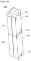
- Figure 9 schematically shows a perspective diagram of a first cell module (second cell module) according to one example of the present invention.
- the first cell module (100) and the second cell module (200) are disposed in a line in the longitudinal direction (Y-axis direction) of the battery cell.
- the y-axis direction represents the longitudinal direction of the battery cell (or case), and the z-axis direction represents the radial direction of the battery cell (or case).
- the first cell module (100) and the second cell module (200) have the same structure.
- the same names are used for the same components, and reference numerals for components equipped in the first cell module (100) and the second cell module (200) are assigned differently.
- first and second connection tabs may each be formed of a metal material having electrical conductivity.
- the first cell module (100) may comprise a case (110), a plurality of battery cells (130), a first connection tab (150), a second connection tab (170), and a support rib (190).
- the second cell module (200) may comprise a case (210), a plurality of battery cells (230), a first connection tab (250), a second connection tab (270), and a support rib (290).
- the case (110) has a cylindrical structure opened in the longitudinal direction (Y) of the battery cell.
- the case (110) is provided with at least one groove portion (115) on the outer peripheral surface of the first end (113) side.
- the plurality of battery cells (130) is each accommodated in an internal space (112) of the case (110).
- Each battery cell (130) has a first electrode terminal (131) and a second electrode terminal (132).
- each battery cell may be disposed so that the first electrode terminal (131) faces the first end (113) side of the case (110), and may be disposed so that the second electrode terminal (132) faces the second end (114) side of the case.
- the support rib (190) is mounted in the internal space (112) of the case (110).
- the support rib (190) supports the plurality of battery cells (130) so that the respective battery cells (130) are disposed to be spaced apart inside the case (110).
- the first connection tab (150) is connected to the first electrode terminal (131) and is exposed to the first end (113) side of the case (110).
- the first electrode terminal (131) may be a positive electrode or a negative electrode
- the second electrode terminal (132) may have an opposite polarity to the first electrode terminal (131).
- the first connection tab (150) has a first tab portion (151), and a first bent portion (155) bent from the first tab portion (151). Specifically, the first connection tab (150) has a first tab portion (151) in contact with the first electrode terminal (131) at the first end (113) side of the case (110), and a first bent portion (155) bent at the first tab portion (151) to be in contact with the outer peripheral surface (111) of the first end (113) side of the case (110).
- the first tab portion (151) may extend along the radial direction (z-axis direction) of the battery cell (130), and the first bent portion (155) may extend along the longitudinal direction (y-axis direction) of the battery cell (130).
- the first tab portion (151) and the first bent portion (155) may be provided to be orthogonal to each other.
- the first connection tab (150) is mounted on the case (110) so that the first tab portion (151) is in contact with the first electrode terminal (131) at the first end (113) side of the case (110), and the first bent portion (155) is in contact with the outer peripheral surface (111) of the first end (113) side of the case (110).
- the first connection tab (150) is mounted on the case (110) so that the first bent portion (155) is seated in the groove portion (115).
- the inner surface (157) of the first bent portion (155) is in contact with the groove portion (115).
- the first tab portion (251) may extend along the radial direction (z-axis direction) of the battery cell (230), and the first bent portion (255) may extend along the longitudinal direction (y-axis direction) of the battery cell (230).
- the first tab portion (251) and the first bent portion (255) may be provided to be orthogonal to each other.
- the second connection tab (270) is electrically connected to the second electrode terminal (232) and extends to the outside of the second end (214) of the case (210), which is opposite to the first end (213).
- the second connection tab (270) has a second tab portion (271), and a second bent portion (275) bent at the second tab portion (271). Specifically, the second connection tab (270) has a second tab portion (271) in contact with the second electrode terminal (232) at the second end (214) side of the case (210), and a second bent portion (275) bent at the second tab portion (271) to extend to the outside of the second end (214).
- the second tab portion (271) may extend along the radial direction (z-axis direction) of the battery cell (230), and the second bent portion (275) may extend along the longitudinal direction (y-axis direction) of the battery cell (230).
- the second tab portion (271) and the second bent portion (275) may be disposed to be orthogonal to each other.
- the second connection tab (270) may be mounted on the second end (214) side of the case (210) so that the inner surface (277) of the second bent portion (275) lies on the same virtual plane (L1) as the outer surface (211) of the case (210), and the outer surface (278) of the second bent portion (275) is stepped with respect to the outer surface (211) of the case (210).
- the battery pack (1000) comprises a circuit board part (500) electrically connecting the first cell module (100) and the second cell module (200) in a state where the first cell module (100) and the second cell module (200) are sequentially arranged.
- the first cell module (100) and the second cell module (200) are sequentially arranged in the longitudinal direction (Y) of the battery cell.
- the second tab portion (171) of the second connection tab (170) equipped in the first cell module (100) is disposed to be spaced apart from the first tab portion (251) of the first connection tab (250) equipped in the second cell module (200).
- the second bent portion (175) of the second connection tab (170) equipped in the first cell module (100) is disposed on the first bent portion (255) of the first connection tab (250) equipped in the second cell module (200).
- the outer surface of the first bent portion (255) may be located on the same virtual plane (L1) as the outer surface of the case (210).
- the second bent portion (175) of the second connection tab (170) equipped in the first cell module (100) is laminated on the first bent portion (255) of the first connection tab (250) equipped in the second cell module (200) in a direction (z) different from the longitudinal direction (y-axis direction) of the battery cell.
- the inner surface (177) of the second bent portion (175) of the first cell module (100) may be in contact with the outer surface (258) of the first bent portion (255) of the second cell module (200).
- the circuit board part (500) is disposed on the first cell module (100) and the second cell module (200) to cover the second bent portion (175) of the first cell module (100). Particularly, the circuit board part (500) is disposed so that the connector (530) covers the second bent portion (175) of the first cell module (100).
- the circuit board part (500) may electrically connect the first cell module (100) and the second cell module (200), and as the circuit board part (500), a flexible printed circuit board (FPCB) may be used.
- FPCB flexible printed circuit board
- the connector (530) may be located on the second connection tab (170) of the first cell module (100), and the connector (530) may be connected to the first connection tab (250) of the second cell module (200) via the second connection tab (170) of the first cell module (100).
- the first bent portion (155) of the second cell module (200), the second bent portion (175) of the first cell module (100), and the circuit board part (300) are laminated and disposed in a direction (z-axis direction) different from the longitudinal direction (y-axis direction) of the battery cell.
- the second bent portion (175) protruding to the other side of the first cell module (100) is disposed between the first bent portion (255) of the first connection tab (250) disposed on one side of the second cell module (200) and the circuit board part (500).
- the circuit board part (500) is disposed on the first cell module (100) and the second cell module (200) so that the connector (530) covers the second bent portion (175), and the connector (530) is welded and coupled to the second bent portion (175) of the first cell module (100) and the first bent portion (255) of the second cell module (200).
- the connector (530) is welded and coupled to the second bent portion (175) of the first cell module (100) and the first bent portion (155) of the second cell module (200).
- the circuit board part (300) may be vertically irradiated with a welding beam (W) in a direction (Z) different from the longitudinal direction of the battery cell.
- the connector (530) of the circuit board part (500) is welded once to the second connection tab (170) of the first cell module (100) and the first connection tab (250) of the second cell module (200), whereby it is possible to electrically connect the first The cell module (100) and the second cell module (200).
- the conventional battery pack (1) assembly process required at least two welding processes to connect two cell modules (10, 20), but on the other hand, by changing the structure of the connection tab, the present invention can electrically connect two cell modules (100, 200) through one welding per connector (530) upon the assembly process of the battery pack (1000).
- the battery pack related to one example of the present invention it is possible to reduce the number of welds upon the assembly process of the battery pack composed of a plurality of cell modules.
Landscapes
- Chemical & Material Sciences (AREA)
- Chemical Kinetics & Catalysis (AREA)
- Electrochemistry (AREA)
- General Chemical & Material Sciences (AREA)
- Battery Mounting, Suspending (AREA)
- Connection Of Batteries Or Terminals (AREA)
Applications Claiming Priority (2)
| Application Number | Priority Date | Filing Date | Title |
|---|---|---|---|
| KR1020220182097A KR20240100036A (ko) | 2022-12-22 | 2022-12-22 | 배터리 팩 |
| PCT/KR2023/095123 WO2024136629A1 (ko) | 2022-12-22 | 2023-12-19 | 배터리 팩 |
Publications (2)
| Publication Number | Publication Date |
|---|---|
| EP4576404A1 true EP4576404A1 (de) | 2025-06-25 |
| EP4576404A4 EP4576404A4 (de) | 2026-03-25 |
Family
ID=91589577
Family Applications (1)
| Application Number | Title | Priority Date | Filing Date |
|---|---|---|---|
| EP23907912.2A Pending EP4576404A4 (de) | 2022-12-22 | 2023-12-19 | Batteriepack |
Country Status (5)
| Country | Link |
|---|---|
| EP (1) | EP4576404A4 (de) |
| JP (1) | JP7802961B2 (de) |
| KR (1) | KR20240100036A (de) |
| CN (1) | CN119072823A (de) |
| WO (1) | WO2024136629A1 (de) |
Families Citing this family (1)
| Publication number | Priority date | Publication date | Assignee | Title |
|---|---|---|---|---|
| CN120691056A (zh) * | 2025-06-09 | 2025-09-23 | 中创新航科技集团股份有限公司 | 电池及用电装置 |
Family Cites Families (12)
| Publication number | Priority date | Publication date | Assignee | Title |
|---|---|---|---|---|
| KR100659858B1 (ko) * | 2005-11-02 | 2006-12-19 | 삼성에스디아이 주식회사 | 배터리 팩 |
| JP5030499B2 (ja) * | 2006-07-31 | 2012-09-19 | 三洋電機株式会社 | パック電池 |
| US8557411B2 (en) * | 2009-08-14 | 2013-10-15 | Samsung Sdi Co., Ltd. | Secondary battery with a connection tab folded around an insulator and method of manufacturing the same |
| KR101621099B1 (ko) * | 2009-12-18 | 2016-05-16 | 삼성에스디아이 주식회사 | 전지 팩 및 그의 제조 방법 |
| KR101312425B1 (ko) * | 2010-02-16 | 2013-09-27 | 주식회사 엘지화학 | 이차 전지용 전지팩 및 이에 사용되는 컨넥터 |
| JP2011258332A (ja) * | 2010-06-07 | 2011-12-22 | Sanyo Electric Co Ltd | パック電池 |
| KR101158810B1 (ko) * | 2010-07-30 | 2012-06-26 | 주식회사 씨엔플러스 | 배터리 팩의 보호회로 기판 및 이를 구비한 배터리 팩 |
| KR101106094B1 (ko) * | 2010-09-13 | 2012-01-18 | 삼성에스디아이 주식회사 | 배터리 팩 |
| US9356277B2 (en) * | 2012-01-31 | 2016-05-31 | Samsung Sdi Co., Ltd. | Battery pack including spacer receiving conductive member |
| JP7016797B2 (ja) * | 2016-03-16 | 2022-02-07 | 株式会社エンビジョンAescジャパン | 電池パック及び電池パックの製造方法 |
| JP7054892B2 (ja) * | 2017-09-19 | 2022-04-15 | エリーパワー株式会社 | 組電池及び組電池の製造方法 |
| CN116368671A (zh) * | 2021-02-23 | 2023-06-30 | 株式会社 Lg新能源 | 电池模块及其制造方法 |
-
2022
- 2022-12-22 KR KR1020220182097A patent/KR20240100036A/ko active Pending
-
2023
- 2023-12-19 JP JP2024560907A patent/JP7802961B2/ja active Active
- 2023-12-19 EP EP23907912.2A patent/EP4576404A4/de active Pending
- 2023-12-19 WO PCT/KR2023/095123 patent/WO2024136629A1/ko not_active Ceased
- 2023-12-19 CN CN202380036099.8A patent/CN119072823A/zh active Pending
Also Published As
| Publication number | Publication date |
|---|---|
| JP2025513911A (ja) | 2025-04-30 |
| WO2024136629A1 (ko) | 2024-06-27 |
| JP7802961B2 (ja) | 2026-01-20 |
| KR20240100036A (ko) | 2024-07-01 |
| EP4576404A4 (de) | 2026-03-25 |
| CN119072823A (zh) | 2024-12-03 |
Similar Documents
| Publication | Publication Date | Title |
|---|---|---|
| EP1812982B1 (de) | Sekundärbatteriepack mit anordnung zu alternativer ausrichtung | |
| EP3651236B1 (de) | Batteriemodul und batteriepack damit | |
| US7642746B2 (en) | Method of preparing battery core pack | |
| EP3561906B1 (de) | Batteriemodul | |
| EP4053989B1 (de) | Batteriemodul mit stromschiene, batteriepack und fahrzeug | |
| JP5044108B2 (ja) | 電池間接続装置 | |
| EP3940867B1 (de) | Batteriepack mit verbesserter struktur zur kurzschlussvermeidung und stossschutz | |
| US12160023B2 (en) | Battery cell having a plurality of electrodes and battery module using the same | |
| KR20200091687A (ko) | 전극 조립체 및 이차 전지 | |
| EP4068490B1 (de) | Batteriezelle, batterie, elektrische vorrichtung, herstellungsverfahren und vorrichtung für eine batteriezelle | |
| KR102505612B1 (ko) | 배터리 팩 | |
| EP4207448A2 (de) | Sammelschienenhalter, sammelschienenanordnung und batteriemodul | |
| EP4576404A1 (de) | Batteriepack | |
| EP4087042A1 (de) | Laminierte stromschiene für energiespeichervorrichtung | |
| CN114930631A (zh) | 电池模块及包括该电池模块的电池组和车辆 | |
| EP4175051B1 (de) | Sekundärbatterie | |
| EP4456310B1 (de) | Wiederaufladbares batteriepack | |
| KR102517098B1 (ko) | 배터리 모듈 | |
| KR101941257B1 (ko) | 커넥터 및 이를 포함하는 배터리 모듈 | |
| KR20240033651A (ko) | 전지 모듈 | |
| JP2024138573A (ja) | 電池モジュール、及び当該電池モジュールの製造方法 | |
| EP4411968A1 (de) | Sammelschiene für ein batteriemodul und batteriemodul damit | |
| KR20180045097A (ko) | 배터리 팩 | |
| WO2026006981A1 (zh) | 电池单体、电池、用电装置及储能装置 | |
| CN119542685A (zh) | 电池包 |
Legal Events
| Date | Code | Title | Description |
|---|---|---|---|
| STAA | Information on the status of an ep patent application or granted ep patent |
Free format text: STATUS: THE INTERNATIONAL PUBLICATION HAS BEEN MADE |
|
| PUAI | Public reference made under article 153(3) epc to a published international application that has entered the european phase |
Free format text: ORIGINAL CODE: 0009012 |
|
| STAA | Information on the status of an ep patent application or granted ep patent |
Free format text: STATUS: REQUEST FOR EXAMINATION WAS MADE |
|
| 17P | Request for examination filed |
Effective date: 20250319 |
|
| AK | Designated contracting states |
Kind code of ref document: A1 Designated state(s): AL AT BE BG CH CY CZ DE DK EE ES FI FR GB GR HR HU IE IS IT LI LT LU LV MC ME MK MT NL NO PL PT RO RS SE SI SK SM TR |
|
| A4 | Supplementary search report drawn up and despatched |
Effective date: 20260223 |
|
| RIC1 | Information provided on ipc code assigned before grant |
Ipc: H01M 50/533 20210101AFI20260217BHEP Ipc: H01M 50/516 20210101ALI20260217BHEP Ipc: H01M 50/519 20210101ALI20260217BHEP Ipc: H01M 50/24 20210101ALI20260217BHEP Ipc: H01M 50/213 20210101ALI20260217BHEP |
|
| DAV | Request for validation of the european patent (deleted) | ||
| DAX | Request for extension of the european patent (deleted) |