EP4576332A1 - Cooling plate, method for producing cooling plate, and battery pack - Google Patents
Cooling plate, method for producing cooling plate, and battery pack Download PDFInfo
- Publication number
- EP4576332A1 EP4576332A1 EP24220754.6A EP24220754A EP4576332A1 EP 4576332 A1 EP4576332 A1 EP 4576332A1 EP 24220754 A EP24220754 A EP 24220754A EP 4576332 A1 EP4576332 A1 EP 4576332A1
- Authority
- EP
- European Patent Office
- Prior art keywords
- thermally conductive
- tube
- flow tube
- cooling plate
- flow
- Prior art date
- Legal status (The legal status is an assumption and is not a legal conclusion. Google has not performed a legal analysis and makes no representation as to the accuracy of the status listed.)
- Pending
Links
Images


Classifications
-
- H—ELECTRICITY
- H01—ELECTRIC ELEMENTS
- H01M—PROCESSES OR MEANS, e.g. BATTERIES, FOR THE DIRECT CONVERSION OF CHEMICAL ENERGY INTO ELECTRICAL ENERGY
- H01M10/00—Secondary cells; Manufacture thereof
- H01M10/60—Heating or cooling; Temperature control
- H01M10/61—Types of temperature control
- H01M10/613—Cooling or keeping cold
-
- H—ELECTRICITY
- H01—ELECTRIC ELEMENTS
- H01M—PROCESSES OR MEANS, e.g. BATTERIES, FOR THE DIRECT CONVERSION OF CHEMICAL ENERGY INTO ELECTRICAL ENERGY
- H01M10/00—Secondary cells; Manufacture thereof
- H01M10/60—Heating or cooling; Temperature control
- H01M10/62—Heating or cooling; Temperature control specially adapted for specific applications
- H01M10/625—Vehicles
-
- H—ELECTRICITY
- H01—ELECTRIC ELEMENTS
- H01M—PROCESSES OR MEANS, e.g. BATTERIES, FOR THE DIRECT CONVERSION OF CHEMICAL ENERGY INTO ELECTRICAL ENERGY
- H01M10/00—Secondary cells; Manufacture thereof
- H01M10/60—Heating or cooling; Temperature control
- H01M10/65—Means for temperature control structurally associated with the cells
- H01M10/653—Means for temperature control structurally associated with the cells characterised by electrically insulating or thermally conductive materials
-
- H—ELECTRICITY
- H01—ELECTRIC ELEMENTS
- H01M—PROCESSES OR MEANS, e.g. BATTERIES, FOR THE DIRECT CONVERSION OF CHEMICAL ENERGY INTO ELECTRICAL ENERGY
- H01M10/00—Secondary cells; Manufacture thereof
- H01M10/60—Heating or cooling; Temperature control
- H01M10/65—Means for temperature control structurally associated with the cells
- H01M10/655—Solid structures for heat exchange or heat conduction
- H01M10/6556—Solid parts with flow channel passages or pipes for heat exchange
-
- H—ELECTRICITY
- H01—ELECTRIC ELEMENTS
- H01M—PROCESSES OR MEANS, e.g. BATTERIES, FOR THE DIRECT CONVERSION OF CHEMICAL ENERGY INTO ELECTRICAL ENERGY
- H01M10/00—Secondary cells; Manufacture thereof
- H01M10/60—Heating or cooling; Temperature control
- H01M10/65—Means for temperature control structurally associated with the cells
- H01M10/655—Solid structures for heat exchange or heat conduction
- H01M10/6556—Solid parts with flow channel passages or pipes for heat exchange
- H01M10/6557—Solid parts with flow channel passages or pipes for heat exchange arranged between the cells
-
- H—ELECTRICITY
- H01—ELECTRIC ELEMENTS
- H01M—PROCESSES OR MEANS, e.g. BATTERIES, FOR THE DIRECT CONVERSION OF CHEMICAL ENERGY INTO ELECTRICAL ENERGY
- H01M10/00—Secondary cells; Manufacture thereof
- H01M10/60—Heating or cooling; Temperature control
- H01M10/65—Means for temperature control structurally associated with the cells
- H01M10/656—Means for temperature control structurally associated with the cells characterised by the type of heat-exchange fluid
- H01M10/6567—Liquids
-
- H—ELECTRICITY
- H01—ELECTRIC ELEMENTS
- H01M—PROCESSES OR MEANS, e.g. BATTERIES, FOR THE DIRECT CONVERSION OF CHEMICAL ENERGY INTO ELECTRICAL ENERGY
- H01M10/00—Secondary cells; Manufacture thereof
- H01M10/60—Heating or cooling; Temperature control
- H01M10/65—Means for temperature control structurally associated with the cells
- H01M10/656—Means for temperature control structurally associated with the cells characterised by the type of heat-exchange fluid
- H01M10/6567—Liquids
- H01M10/6568—Liquids characterised by flow circuits, e.g. loops, located externally to the cells or cell casings
-
- F—MECHANICAL ENGINEERING; LIGHTING; HEATING; WEAPONS; BLASTING
- F28—HEAT EXCHANGE IN GENERAL
- F28D—HEAT-EXCHANGE APPARATUS, NOT PROVIDED FOR IN ANOTHER SUBCLASS, IN WHICH THE HEAT-EXCHANGE MEDIA DO NOT COME INTO DIRECT CONTACT
- F28D1/00—Heat-exchange apparatus having stationary conduit assemblies for one heat-exchange medium only, the media being in contact with different sides of the conduit wall, in which the other heat-exchange medium is a large body of fluid, e.g. domestic or motor car radiators
- F28D1/02—Heat-exchange apparatus having stationary conduit assemblies for one heat-exchange medium only, the media being in contact with different sides of the conduit wall, in which the other heat-exchange medium is a large body of fluid, e.g. domestic or motor car radiators with heat-exchange conduits immersed in the body of fluid
- F28D1/04—Heat-exchange apparatus having stationary conduit assemblies for one heat-exchange medium only, the media being in contact with different sides of the conduit wall, in which the other heat-exchange medium is a large body of fluid, e.g. domestic or motor car radiators with heat-exchange conduits immersed in the body of fluid with tubular conduits
- F28D1/047—Heat-exchange apparatus having stationary conduit assemblies for one heat-exchange medium only, the media being in contact with different sides of the conduit wall, in which the other heat-exchange medium is a large body of fluid, e.g. domestic or motor car radiators with heat-exchange conduits immersed in the body of fluid with tubular conduits the conduits being bent, e.g. in a serpentine or zig-zag
- F28D1/0477—Heat-exchange apparatus having stationary conduit assemblies for one heat-exchange medium only, the media being in contact with different sides of the conduit wall, in which the other heat-exchange medium is a large body of fluid, e.g. domestic or motor car radiators with heat-exchange conduits immersed in the body of fluid with tubular conduits the conduits being bent, e.g. in a serpentine or zig-zag the conduits being bent in a serpentine or zig-zag
- F28D1/0478—Heat-exchange apparatus having stationary conduit assemblies for one heat-exchange medium only, the media being in contact with different sides of the conduit wall, in which the other heat-exchange medium is a large body of fluid, e.g. domestic or motor car radiators with heat-exchange conduits immersed in the body of fluid with tubular conduits the conduits being bent, e.g. in a serpentine or zig-zag the conduits being bent in a serpentine or zig-zag the conduits having a non-circular cross-section
-
- F—MECHANICAL ENGINEERING; LIGHTING; HEATING; WEAPONS; BLASTING
- F28—HEAT EXCHANGE IN GENERAL
- F28F—DETAILS OF HEAT-EXCHANGE AND HEAT-TRANSFER APPARATUS, OF GENERAL APPLICATION
- F28F21/00—Constructions of heat-exchange apparatus characterised by the selection of particular materials
- F28F21/06—Constructions of heat-exchange apparatus characterised by the selection of particular materials of plastics material
-
- F—MECHANICAL ENGINEERING; LIGHTING; HEATING; WEAPONS; BLASTING
- F28—HEAT EXCHANGE IN GENERAL
- F28F—DETAILS OF HEAT-EXCHANGE AND HEAT-TRANSFER APPARATUS, OF GENERAL APPLICATION
- F28F2275/00—Fastening; Joining
- F28F2275/02—Fastening; Joining by using bonding materials; by embedding elements in particular materials
-
- F—MECHANICAL ENGINEERING; LIGHTING; HEATING; WEAPONS; BLASTING
- F28—HEAT EXCHANGE IN GENERAL
- F28F—DETAILS OF HEAT-EXCHANGE AND HEAT-TRANSFER APPARATUS, OF GENERAL APPLICATION
- F28F3/00—Plate-like or laminated elements; Assemblies of plate-like or laminated elements
- F28F3/02—Elements or assemblies thereof with means for increasing heat-transfer area, e.g. with fins, with recesses, with corrugations
-
- Y—GENERAL TAGGING OF NEW TECHNOLOGICAL DEVELOPMENTS; GENERAL TAGGING OF CROSS-SECTIONAL TECHNOLOGIES SPANNING OVER SEVERAL SECTIONS OF THE IPC; TECHNICAL SUBJECTS COVERED BY FORMER USPC CROSS-REFERENCE ART COLLECTIONS [XRACs] AND DIGESTS
- Y02—TECHNOLOGIES OR APPLICATIONS FOR MITIGATION OR ADAPTATION AGAINST CLIMATE CHANGE
- Y02E—REDUCTION OF GREENHOUSE GAS [GHG] EMISSIONS, RELATED TO ENERGY GENERATION, TRANSMISSION OR DISTRIBUTION
- Y02E60/00—Enabling technologies; Technologies with a potential or indirect contribution to GHG emissions mitigation
- Y02E60/10—Energy storage using batteries
Definitions
- the present disclosure relates to the field of battery cooling technologies, and in particular to a vertical cooling plate, a method for producing a vertical cooling plate, and a battery pack.
- the liquid cooling plates are usually stamped and brazed liquid cooling plates made of aluminum alloy.
- the liquid cooling plates are not only heavy and not conducive to lightweight, but also costly.
- welding defects generated between the components may not only affect the flatness of the liquid cooling plates and reduce the heat exchange efficiency of the liquid cooling plates, but also greatly reduce the strength of the liquid cooling plates.
- the liquid cooling plates have certain safety hazards during use.
- the present disclosure provides a vertical cooling plate, a method for producing a vertical cooling plate, and a battery pack to solve the problem of high cost and poor safety of liquid cooling plates in related art.
- the present disclosure provides a vertical cooling plate, and the vertical cooling plate is configured to be fitted on a surface of a battery cell perpendicular to a thickness direction of the battery cell for exchanging heat with the battery cell.
- the vertical cooling plate includes a flow tube and a thermally conductive plate.
- the flow tube includes a plastic thermally conductive member.
- the thermally conductive plate includes a flexible thermally conductive member.
- the thermally conductive plate is directly molded on a surface of the flow tube by infusion, enabling the thermally conductive plate to wrap the flow tube.
- the flow tube is defined with a flow cavity.
- the flow cavity is configured for a heat exchange medium to pass through.
- the thermally conductive plate is configured to be fitted on the battery cell, enabling the heat exchange medium to receive heat transferred from the battery cell via the thermally conductive plate and the flow tube.
- the present disclosure also provides a battery pack including a plurality of battery cells and a plurality of vertical cooling plates according to any one of embodiments mentioned above.
- the plurality of battery cells are arranged separate from each other along a thickness direction of the battery cells.
- Each of the vertical cooling plates is arranged between two adjacent battery cells and connected to the two adjacent battery cells.
- the present disclosure further provides a method for producing a vertical cooling plate configured to produce the vertical cooling plate mentioned above.
- the method for producing the vertical cooling plate includes: processing thermally conductive plastic into a flow tube defined with a flow cavity; and casting thermally conductive silicone on an outer surface of the flow tube to form a thermally conductive plate, enabling the thermally conductive plate to wrap the outer surface of the flow tube.
- the present disclosure provides the vertical cooling plate, the method for producing the vertical cooling plate, and the battery pack.
- the vertical cooling plate is fitted on the surface of the battery cell perpendicular to the thickness direction of the battery cell, that is, fitted on a large surface of the battery cell for cooling.
- a contact area between the vertical cooling plate and the battery cell is significantly increased, thereby effectively enhancing a cooling strength for the battery cell, alleviating the problem of uneven heat dissipation of the battery cell, and improving the operational reliability of the battery cell.
- the flow tube including the plastic thermally conductive member by providing the flow tube including the plastic thermally conductive member, a heat conducting performance of the flow tube may be ensured, and the material cost of the vertical cooling plate is reduced because of low cost of plastic. Moreover, the weight of plastic is lighter than the weight of aluminum alloys, thereby effectively reducing the weight of the vertical cooling plate and meeting lightweight requirements.
- the thermally conductive plate including the flexible thermally conductive member by providing the thermally conductive plate including the flexible thermally conductive member, the thermally conductive plate may be better fitted on the battery cell because of the flexibility of the thermally conductive plate, thereby improving the contact effect between the thermally conductive plate and the battery cell, and greatly improving the heat exchange efficiency between the vertical cooling plate and the battery cell.
- the flexible thermally conductive plate is conducive to absorb the tolerance of the battery cell or absorb the expansion force of the battery cell after the battery cell cyclically expands, so as to avoid the expansion force of the battery cell from squeezing the flow tube, causing the flow tube to rupture, thereby causing the heat exchange medium to leak from the flow tube.
- the vertical cooling plate may ensure a relatively high level of safety after long-term use.
- the thermally conductive plate is directly molded on the surface of the flow tube by means of infusion.
- the producing method is simple for molding, may effectively shorten assembly steps of the thermally conductive plate and the flow tube, thereby improving the molding efficiency of the vertical cooling plate. Furthermore, the producing method avoids disadvantages of high energy consumption of related brazing process and adverse effects of brazing on the flatness of the product, thereby further improving the heat exchange efficiency and reducing costs.
- an assembly when an assembly is referred to as being “fixed on” or “arranged on” another assembly, the assembly may be directly on the another assembly, or there may be a middle assembly between the assembly and the another assembly.
- an assembly When an assembly is considered to be “connected to” another assembly, the assembly may be directly connected to the another assembly, or there may be a middle assembly between the assembly and the another assembly.
- the terms “vertical”, “horizontal”, “upper”, “lower”, “left”, “right”, and similar expressions used in the specification of the present disclosure are for illustrative purposes only and do not represent an only implementation method.
- first and second are configured for descriptive purposes only and should not be understood as indicating or implying relative importance or implicitly indicating the number of the indicated technical features. Therefore, the features defined as “first” and “second” may explicitly or implicitly include at least one of the features. In the description of the present disclosure, the meaning of "a plurality of” is at least two, such as two, three, etc., unless otherwise clearly and specifically limited.
- a first feature being “on” or “under” a second feature may mean that the first feature is directly in contact with the second feature, or the first feature and the second feature are in contact indirectly through an middle medium.
- a first feature being “on”, “above”, or “over” a second feature may mean that the first feature is exactly above or obliquely above the second feature, or simply means that a horizontal height of the first feature is higher than a horizontal height of the second feature.
- a first feature being "under”, “below”, or “beneath” a second feature may mean that the first feature is exactly below or obliquely below the second feature, or simply means that a horizontal height of the first feature is lower than a horizontal height of the second feature.
- the present disclosure provides the vertical cooling plate 100 including a flow tube 10 and a thermally conductive plate 20.
- the flow tube 10 includes a plastic thermally conductive member.
- the thermally conductive plate 20 includes a flexible thermally conductive member.
- the thermally conductive plate 20 is directly molded on a surface of the flow tube 10 by infusion, enabling the thermally conductive plate 20 to be able to wrap the flow tube 10.
- the flow tube 10 is defined with a flow cavity 101.
- the flow cavity 101 is configured for a heat exchange medium to pass through.
- the thermally conductive plate 20 is configured to be fitted on the battery cell, enabling the heat exchange medium to receive heat transferred from the battery cell via the thermally conductive plate 20 and the flow tube 10.
- the flexible thermally conductive plate 20 is conducive to absorb the tolerance of the battery cell or absorb the expansion force of the battery cell after the battery cell cyclically expands, so as to avoid the expansion force of the battery cell from squeezing the flow tube 10, causing the flow tube 10 to rupture, thereby causing the heat exchange medium to leak from the flow tube 10.
- the vertical cooling plate 100 may ensure a relatively high level of safety after long-term use.
- the thermally conductive plate 20 is directly molded on the surface of the flow tube 10 by means of infusion.
- the producing method is simple for molding, may effectively shorten assembly steps of the thermally conductive plate 20 and the flow tube 10, thereby improving the molding efficiency of the vertical cooling plate 100.
- the producing method avoids disadvantages of high energy consumption of related brazing process and adverse effects of brazing on the flatness of the product, thereby further improving the heat exchange efficiency and reducing costs.
- the flow tube 10 includes a plurality of branch tubes 11 and a bent tube 12.
- the plurality of branch tubes 11 are arranged separated from each other along a width direction of the vertical cooling plate 100.
- the bent tube 12 is connected to ends of two adjacent branch tubes 11 facing a same side and is communicated with the two adjacent branch tubes 11.
- the branch tubes 11 are configured as long straight tubes, and the bent tube 12 is configured as a U-shaped tube. Both the branch tubes 11 and the bent tube 12 are arranged in a flat shape.
- a thickness direction of the branch tubes 11 and the bent tube 12 is the same as a thickness direction of the thermally conductive plate 20. Both the thickness direction of the branch tubes 11 and the bent tube 12 and the thickness direction of the thermally conductive plate 20 are the thickness direction of the battery cell. It is easy to understand that the branch tubes 11 and the bent tube 12 achieve indirect contact with the battery cell through large surfaces of the branch tubes 11 and the bent tube 12, further increasing contact areas and effectively reducing a heat transfer distance between the flow tube 10 and the battery cell, thereby achieving effective transfer of heat and significantly improving the heat exchange efficiency. In addition, the thickness of the thermally conductive plate 20 may be reduced, and the space utilization rate may be improved.
- the branch tubes 11 and the bent tube 12 are integrally bent and formed. That is, the bent tube 12 may be bent and formed by taking advantage of thermoplastic of plastic. In this way, the structural strength of the flow tube 10 is significantly improved, the processing difficulty of the branch tubes 11 and the bent tube 12 is reduced, and the assembly efficiency of the branch tubes 11 and the bent tube 12 is enhanced.
- the branch tubes 11 and the bent tube 12 are separate structures.
- the branch tubes 11 and the bent tube 12 are fixed with each other by welding.
- the branch tubes 11 and the bent tube 12 may also be fixedly connected by means of welding.
- a bending radius of the bent tube 12 is easier to control, thereby improving the processing and fitting accuracy of components.
- the inlet tube 30 and the outlet tube 40 are fixed to the flow tube 10 by means of welding.
- the inlet tube 30 is defined with an inlet for the heat exchange medium.
- the outlet tube 40 is defined with an outlet for the heat exchange medium. When flowing, the heat exchange medium enters the flow cavity 101 through the inlet tube 30 and flows out of the flow cavity 101 through the outlet tube 40.
- the arrangement of the inlet tube 30 and the outlet tube 40 is conducive to the connection and fixation of the flow tube 10 and external cooling tubes, thereby facilitating inflow and outflow of the heat exchange medium.
- the inlet tube 30 and the outlet tube 40 are arranged on opposite sides of the vertical cooling plate 100 along a length direction of the branch tubes 11. In this way, interference is less likely to occur between external cooling tubes connected to the inlet tube 30 and external cooling tubes connected to the outlet tube 40, thereby facilitating layout of tubes and improving the reliability of a device.
- a material of the thermally conductive plate 20 includes thermally conductive silicone.
- the thermally conductive silicone provided in the present disclosure is a type of material formed by using a silicone as a silicone matrix and filling a thermally conductive material within the silicone matrix.
- the thermally conductive silicone has good thermal conductivity and elasticity. Therefore, the thermally conductive plate 20 made of the thermally conductive silicone also has good elasticity and thermal conductivity, which not only meets the heat conduction requirements of the thermally conductive plate 20, but also ensures that the thermally conductive plate 20 may effectively absorb the tolerances between the battery cells and the expansion forces generated during cycling, thereby effectively improving the overall safety.
- the thermally conductive silicone is heated to a molten state, and the molten thermally conductive silicone is injected into a mold in which the flow tube 10 is fixed. As the thermally conductive silicone cools and solidifies, the thermally conductive silicone may be attached to the outer surface of the flow tube 10.
- the thermally conductive plate 20 of the present disclosure may be obtained by cutting off excess thermally conductive silicone. In this way, the forming of the thermally conductive plate 20 is simple, which may effectively increase the processing speed of the thermally conductive plate 20 and reduce costs.
- the elasticity of the thermally conductive silicone may be adjusted by changing an amount of injected material and a magnitude of a pressure.
- the flow tube 10 is arranged in middle of the thermally conductive plate 20 along the thickness direction of the thermally conductive plate 20, thereby ensuring the uniformity of heat transfer and stress on the thermally conductive plate 20 by the flow tube 10.
- the thermally conductive plate 20 is defined with a supporting hole 201.
- the supporting hole 201 is configured for a supporting column on a glue injection mold to pass through, so that the supporting column is able to press the flow tube 10 tightly. In this way, it effectively ensures the firm connection between the flow tube 10 and the mold when the thermally conductive silicone is injected and molded to form the thermally conductive plate 20, thereby avoiding a gap existing between the thermally conductive plate 20 and the flow tube 10 due to shaking of the flow tube 10. Thereby, fitting accuracy between the thermally conductive plate 20 and the flow tube 10 is effectively improved, and qualified rate of the product is enhanced.
- a number of the supporting hole 201 is more than one.
- the more than one supporting hole 201 are arranged separated from each other on the thermally conductive plate 20. In this way, fixing effect between the flow tube 10 and the mold may be further improved.
- the present disclosure also provides a battery pack.
- the battery pack includes a plurality of battery cells and a plurality of vertical cooling plates 100 described in any one of the above embodiments.
- the plurality of battery cells are arranged separated from each other along a thickness direction of the battery cells.
- Each of the vertical cooling plates 100 is arranged between two adjacent battery cells and connected to the two adjacent battery cells.
- the battery cells and the vertical cooling plates 100 are stacked in sequence along the thickness direction of the battery cells.
- the vertical cooling plates 100 may be fitted on both large surfaces of the two adjacent battery cells to achieve cooling, thereby improving the heat exchange efficiency and ensuring the uniformity of heat exchange.
- the vertical cooling plates 100 may absorb tolerances of the battery cells through the elasticity of the thermally conductive plate 20, thereby facilitating the assembly of the battery cells and reducing the difficulty of assembling the battery cells.
- the vertical cooling plates 100 may also absorb the expansion force through external flexible thermally conductive plate 20, preventing the battery cells from squeezing flow tubes 10 located inside the vertical cooling plates 100 and causing the flow tubes 10 to rupture and leakage, thereby greatly improving the safety performance of the battery pack.
- the vertical cooling plates 100 are bonded to the battery cells by means of double-sided adhesive tapes 200.
- connection between the vertical cooling plates 100 and the battery cells is simple, and bonding and fixing between the vertical cooling plates 100 and the battery cells may be easily implemented.
- the present disclosure also provides a method for producing a vertical cooling plate 100, which is configured to produce the vertical cooling plate 100 mentioned above.
- the method for producing the vertical cooling plate 100 may include operations executed by the following blocks.
- thermally conductive plastic is processed into a flow tube 10 defined with a flow cavity 101.
- thermally conductive silicone is cast on an outer surface of the flow tube 10 to form a thermally conductive plate 20, enabling the thermally conductive plate 20 to wrap the outer surface of the flow tube 10.
- an inlet tube 30 and an outlet tube 40 are respectively welded to two ends of the flow tube 10.
- forming the thermally conductive plate 20 at block S2 may executed by the following blocks.
- the flow tube 10 is installed in a glue injection mold, and a supporting column on the glue injection mold press against the outer surface of the flow tube 10.
- a predetermined amount of molten thermally conductive silicone is poured into the glue injection mold, the thermally conductive silicone wraps the outer surface of the flow tube 10, and a pressure regulating device is used to adjust a pressure on the thermally conductive silicone.
Landscapes
- Engineering & Computer Science (AREA)
- Manufacturing & Machinery (AREA)
- Chemical & Material Sciences (AREA)
- Chemical Kinetics & Catalysis (AREA)
- Electrochemistry (AREA)
- General Chemical & Material Sciences (AREA)
- Secondary Cells (AREA)
Abstract
Description
- The present disclosure relates to the field of battery cooling technologies, and in particular to a vertical cooling plate, a method for producing a vertical cooling plate, and a battery pack.
- During the operation of a battery pack, battery cells inside the battery pack may generate a substantial amount of heat. If the heat is not dissipated in time, a service life of the battery cells may be reduced. At present, liquid cooling plates are usually arranged at bottoms of the battery cells for dissipating the heat generated by the battery cells.
- In related art, the liquid cooling plates are usually stamped and brazed liquid cooling plates made of aluminum alloy. The liquid cooling plates are not only heavy and not conducive to lightweight, but also costly. Moreover, after components made of the aluminum alloy are brazed together, welding defects generated between the components may not only affect the flatness of the liquid cooling plates and reduce the heat exchange efficiency of the liquid cooling plates, but also greatly reduce the strength of the liquid cooling plates. As a result, the liquid cooling plates have certain safety hazards during use.
- The present disclosure provides a vertical cooling plate, a method for producing a vertical cooling plate, and a battery pack to solve the problem of high cost and poor safety of liquid cooling plates in related art.
- The present disclosure provides a vertical cooling plate, and the vertical cooling plate is configured to be fitted on a surface of a battery cell perpendicular to a thickness direction of the battery cell for exchanging heat with the battery cell. The vertical cooling plate includes a flow tube and a thermally conductive plate. The flow tube includes a plastic thermally conductive member. The thermally conductive plate includes a flexible thermally conductive member. The thermally conductive plate is directly molded on a surface of the flow tube by infusion, enabling the thermally conductive plate to wrap the flow tube. The flow tube is defined with a flow cavity. The flow cavity is configured for a heat exchange medium to pass through. The thermally conductive plate is configured to be fitted on the battery cell, enabling the heat exchange medium to receive heat transferred from the battery cell via the thermally conductive plate and the flow tube.
- The present disclosure also provides a battery pack including a plurality of battery cells and a plurality of vertical cooling plates according to any one of embodiments mentioned above. The plurality of battery cells are arranged separate from each other along a thickness direction of the battery cells. Each of the vertical cooling plates is arranged between two adjacent battery cells and connected to the two adjacent battery cells.
- The present disclosure further provides a method for producing a vertical cooling plate configured to produce the vertical cooling plate mentioned above. The method for producing the vertical cooling plate includes: processing thermally conductive plastic into a flow tube defined with a flow cavity; and casting thermally conductive silicone on an outer surface of the flow tube to form a thermally conductive plate, enabling the thermally conductive plate to wrap the outer surface of the flow tube.
- Beneficial effects of the present disclosure are as follows. Different from the related art, the present disclosure provides the vertical cooling plate, the method for producing the vertical cooling plate, and the battery pack. The vertical cooling plate is fitted on the surface of the battery cell perpendicular to the thickness direction of the battery cell, that is, fitted on a large surface of the battery cell for cooling. Compared with related liquid cooling plates arranged at a bottom of the battery cell, a contact area between the vertical cooling plate and the battery cell is significantly increased, thereby effectively enhancing a cooling strength for the battery cell, alleviating the problem of uneven heat dissipation of the battery cell, and improving the operational reliability of the battery cell. Further, on one hand, by providing the flow tube including the plastic thermally conductive member, a heat conducting performance of the flow tube may be ensured, and the material cost of the vertical cooling plate is reduced because of low cost of plastic. Moreover, the weight of plastic is lighter than the weight of aluminum alloys, thereby effectively reducing the weight of the vertical cooling plate and meeting lightweight requirements. On the other hand, by providing the thermally conductive plate including the flexible thermally conductive member, the thermally conductive plate may be better fitted on the battery cell because of the flexibility of the thermally conductive plate, thereby improving the contact effect between the thermally conductive plate and the battery cell, and greatly improving the heat exchange efficiency between the vertical cooling plate and the battery cell. Furthermore, the flexible thermally conductive plate is conducive to absorb the tolerance of the battery cell or absorb the expansion force of the battery cell after the battery cell cyclically expands, so as to avoid the expansion force of the battery cell from squeezing the flow tube, causing the flow tube to rupture, thereby causing the heat exchange medium to leak from the flow tube. The vertical cooling plate may ensure a relatively high level of safety after long-term use. In addition, the thermally conductive plate is directly molded on the surface of the flow tube by means of infusion. The producing method is simple for molding, may effectively shorten assembly steps of the thermally conductive plate and the flow tube, thereby improving the molding efficiency of the vertical cooling plate. Furthermore, the producing method avoids disadvantages of high energy consumption of related brazing process and adverse effects of brazing on the flatness of the product, thereby further improving the heat exchange efficiency and reducing costs.
- In order to illustrate the technical solutions in the embodiments of the present disclosure or in the related art more clearly, the drawings that need to be used in the description in the embodiments or in the related art are briefly introduced below. Obviously, the drawings in the following description are merely some embodiments of the present disclosure. For those skilled in the art, other drawings may also be obtained according to these drawings under the premise of without making creative efforts.
-
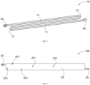
FIG. 1 is a schematic structural view of a vertical cooling plate with a double-sided tape according to some embodiments of the present disclosure. -
FIG. 2 is a schematic cross-sectional view of a vertical cooling plate according to some embodiments of the present disclosure. -
FIG. 3 is a schematic structural view of a flow tube according to some embodiments of the present disclosure. -
FIG. 4 is a schematic main view of a vertical cooling plate according to some embodiments of the present disclosure. -
FIG. 5 is a schematic cross-sectional view of a vertical cooling plate and a double-sided tape according to some embodiments of the present disclosure. - In order to make purposes, features, and beneficial effects of the present disclosure mentioned above more obvious and easy to understand, the specific implementation methods are described in detail below with reference to the accompanying drawings. In the following description, many specific details are set forth to facilitate a full understanding of the present disclosure. However, the present disclosure may be implemented in many other ways different from methods described herein. Those skilled in the art may make similar improvements without violating the connotation of the present disclosure, so the present disclosure is not limited by the embodiments disclosed below.
- It should be noted that when an assembly is referred to as being "fixed on" or "arranged on" another assembly, the assembly may be directly on the another assembly, or there may be a middle assembly between the assembly and the another assembly. When an assembly is considered to be "connected to" another assembly, the assembly may be directly connected to the another assembly, or there may be a middle assembly between the assembly and the another assembly. The terms "vertical", "horizontal", "upper", "lower", "left", "right", and similar expressions used in the specification of the present disclosure are for illustrative purposes only and do not represent an only implementation method.
- In addition, the terms "first" and "second" are configured for descriptive purposes only and should not be understood as indicating or implying relative importance or implicitly indicating the number of the indicated technical features. Therefore, the features defined as "first" and "second" may explicitly or implicitly include at least one of the features. In the description of the present disclosure, the meaning of "a plurality of" is at least two, such as two, three, etc., unless otherwise clearly and specifically limited.
- In the present disclosure, unless otherwise clearly specified and limited, a first feature being "on" or "under" a second feature may mean that the first feature is directly in contact with the second feature, or the first feature and the second feature are in contact indirectly through an middle medium. Moreover, a first feature being "on", "above", or "over" a second feature may mean that the first feature is exactly above or obliquely above the second feature, or simply means that a horizontal height of the first feature is higher than a horizontal height of the second feature. A first feature being "under", "below", or "beneath" a second feature may mean that the first feature is exactly below or obliquely below the second feature, or simply means that a horizontal height of the first feature is lower than a horizontal height of the second feature.
- Unless otherwise defined, all technical terms and scientific terms used in the specification of the present disclosure have the same meanings as commonly understood by those skilled in the art. The terms used in the specification of the present disclosure are only for the purpose of describing the embodiments and are not intended to limit the present disclosure. The term "and/or" used in the specification of the present disclosure includes any and all combinations of one or more related listed items.
- During the operation of a battery pack, battery cells inside the battery pack may generate a substantial amount of heat. If the heat is not dissipated in time, a service life of the battery cells may be reduced. At present, liquid cooling plates are usually arranged at bottoms of the battery cells for dissipating the heat generated by the battery cells.
- In related art, the liquid cooling plates are usually stamped and brazed liquid cooling plates made of aluminum alloy. The liquid cooling plates are not only heavy and not conducive to lightweight, but also costly. Moreover, after components made of the aluminum alloy are brazed together, welding defects generated between the components may not only affect the flatness of the liquid cooling plates and reduce the heat exchange efficiency of the liquid cooling plates, but also greatly reduce the strength of the liquid cooling plates. As a result, the liquid cooling plates have certain safety hazards during use.
- As shown in
FIG. 1 to FIG. 5 , in order to solve the problem of high cost and poor safety of related liquid cooling plates, the present disclosure provides avertical cooling plate 100. Thevertical cooling plate 100 is applied to a battery pack. In some embodiments, a plurality of battery cells (not shown) are arranged in the battery pack. Thevertical cooling plate 100 is configured to be fitted on a surface of a battery cell perpendicular to a thickness direction of the battery cell to perform heat exchange with the battery cell. - In some embodiments, the surface of the battery cell perpendicular to the thickness direction of the battery cell is a large surface of the battery cell. That is, the surface of the battery cell perpendicular to the thickness direction of the battery cell is a side surface with the largest area of the battery cell. The
vertical cooling plate 100 is fitted on the large surface of the battery cell for cooling. Compared with related liquid cooling plates arranged at a bottom of the battery cell, a contact area between thevertical cooling plate 100 and the battery cell is significantly increased, thereby effectively enhancing a cooling strength for the battery cell, alleviating the problem of uneven heat dissipation of the battery cell, and improving the operational reliability of the battery cell. - As shown in
FIG. 2 to FIG. 4 , the present disclosure provides thevertical cooling plate 100 including aflow tube 10 and a thermallyconductive plate 20. Theflow tube 10 includes a plastic thermally conductive member. The thermallyconductive plate 20 includes a flexible thermally conductive member. The thermallyconductive plate 20 is directly molded on a surface of theflow tube 10 by infusion, enabling the thermallyconductive plate 20 to be able to wrap theflow tube 10. Theflow tube 10 is defined with aflow cavity 101. Theflow cavity 101 is configured for a heat exchange medium to pass through. The thermallyconductive plate 20 is configured to be fitted on the battery cell, enabling the heat exchange medium to receive heat transferred from the battery cell via the thermallyconductive plate 20 and theflow tube 10. - On one hand, by providing the
flow tube 10 including the plastic thermally conductive member, a heat conducting performance of theflow tube 10 may be ensured, and the material cost of thevertical cooling plate 100 is reduced because of low cost of plastic. Moreover, the weight of plastic is lighter than the weight of aluminum alloys, thereby effectively reducing the weight of thevertical cooling plate 100 and meeting lightweight requirements. On the other hand, by providing the thermallyconductive plate 20 including the flexible thermally conductive member, the thermallyconductive plate 20 may be better fitted on the battery cell because of the flexibility of the thermallyconductive plate 20, thereby improving the contact effect between the thermallyconductive plate 20 and the battery cell, and greatly improving the heat exchange efficiency between thevertical cooling plate 100 and the battery cell. Furthermore, the flexible thermallyconductive plate 20 is conducive to absorb the tolerance of the battery cell or absorb the expansion force of the battery cell after the battery cell cyclically expands, so as to avoid the expansion force of the battery cell from squeezing theflow tube 10, causing theflow tube 10 to rupture, thereby causing the heat exchange medium to leak from theflow tube 10. Thevertical cooling plate 100 may ensure a relatively high level of safety after long-term use. In addition, the thermallyconductive plate 20 is directly molded on the surface of theflow tube 10 by means of infusion. The producing method is simple for molding, may effectively shorten assembly steps of the thermallyconductive plate 20 and theflow tube 10, thereby improving the molding efficiency of thevertical cooling plate 100. Furthermore, the producing method avoids disadvantages of high energy consumption of related brazing process and adverse effects of brazing on the flatness of the product, thereby further improving the heat exchange efficiency and reducing costs. - In some embodiments, the heat generated by the battery cell is transferred to the heat exchange medium in the
flow cavity 101 through the thermallyconductive plate 20 and theflow tube 10 in sequence, and transfers of the heat is achieved through the flow of the heat exchange medium. The heat exchange medium may be a cooling medium or a high-temperature medium to achieve cooling or heat preservation of the battery cell. - In some embodiments, a material of the
flow tube 10 includes thermally conductive plastic. Theflow tube 10 is extruded and molded by the thermally conductive plastic. In a process of extruding the thermally conductive plastic to form theflow tube 10, the thermally conductive plastic is heated to a molten state, and the molten thermally conductive plastic may be processed into a desired shape through a mold corresponding to the desired shape. In this way, the molding of theflow tube 10 is simple, thereby effectively improving the processing rate of theflow tube 10 and reducing costs. In some embodiments, theflow tube 10 may be processed and molded according to molds of corresponding sizes manufactured according to actual thermal management requirements of different battery packs. - It should be noted that the thermally conductive plastic is a type of material formed by using plastic as a plastic matrix and filling a thermally conductive material within the plastic matrix. The weight of the thermally conductive plastic is light, and compared to the related aluminum alloys, weight reduction of the thermally conductive plastic may reach 40% to 50%. Moreover, the thermally conductive plastic possesses excellent thermal conductivity, insulation properties, and processing capabilities, which may meet different usage requirements. Therefore, the
flow tube 10 made of the thermally conductive plastic may overcome the problem of low thermal conductivity efficiency of related plastic. - It should also be noted that the thermal conductivity of a material is usually represented by a thermal conductivity coefficient. By filling different amounts of thermally conductive materials within a same plastic matrix, a thermal conductivity coefficient of the thermally conductive plastic may be changed accordingly to meet different heat exchange requirements.
- In some embodiments, the plastic matrix may be polyphenylene sulfide (PPS), polyamide 6 (PA6), polyamide 66 (PA66), liquid crystal polymer (LCP), thermoplastic elastomer (TPE), polycarbonate (PC), polypropylene (PP), polyphthalamide (PPA), polyetheretherketone (PEEK), etc. The filled thermally conductive material may be aluminum nitride (AlN), silicon carbide (SiC), aluminum oxide (Al2O3), graphite, fibrous high thermal conductivity carbon powder, flaky high thermal conductivity carbon powder, etc. The material of the plastic matrix and the material of the thermally conductive material are not listed here one by one.
- In some embodiments, as shown in
FIG. 3 , theflow tube 10 includes a plurality ofbranch tubes 11 and abent tube 12. The plurality ofbranch tubes 11 are arranged separated from each other along a width direction of thevertical cooling plate 100. Thebent tube 12 is connected to ends of twoadjacent branch tubes 11 facing a same side and is communicated with the twoadjacent branch tubes 11. - By providing the plurality of
branch tubes 11 and realizing diverting connections between twoadjacent branch tubes 11 through thebent tube 12, a flow direction of the heat exchange medium within theflow cavity 101 may be changed. In a same spatial area, a flow length and a flow area of the heat exchange medium are further increased, thereby effectively improving the heat exchange effect of thevertical cooling plate 100 on the battery cell. - In some embodiments, the
branch tubes 11 are configured as long straight tubes, and thebent tube 12 is configured as a U-shaped tube. Both thebranch tubes 11 and thebent tube 12 are arranged in a flat shape. A thickness direction of thebranch tubes 11 and thebent tube 12 is the same as a thickness direction of the thermallyconductive plate 20. Both the thickness direction of thebranch tubes 11 and thebent tube 12 and the thickness direction of the thermallyconductive plate 20 are the thickness direction of the battery cell. It is easy to understand that thebranch tubes 11 and thebent tube 12 achieve indirect contact with the battery cell through large surfaces of thebranch tubes 11 and thebent tube 12, further increasing contact areas and effectively reducing a heat transfer distance between theflow tube 10 and the battery cell, thereby achieving effective transfer of heat and significantly improving the heat exchange efficiency. In addition, the thickness of the thermallyconductive plate 20 may be reduced, and the space utilization rate may be improved. - In some embodiments, the
branch tubes 11 and thebent tube 12 are integrally bent and formed. That is, thebent tube 12 may be bent and formed by taking advantage of thermoplastic of plastic. In this way, the structural strength of theflow tube 10 is significantly improved, the processing difficulty of thebranch tubes 11 and thebent tube 12 is reduced, and the assembly efficiency of thebranch tubes 11 and thebent tube 12 is enhanced. - In some embodiments, the
branch tubes 11 and thebent tube 12 are separate structures. Thebranch tubes 11 and thebent tube 12 are fixed with each other by welding. Thebranch tubes 11 and thebent tube 12 may also be fixedly connected by means of welding. A bending radius of thebent tube 12 is easier to control, thereby improving the processing and fitting accuracy of components. - In some embodiments, as shown in
FIG. 2 , thevertical cooling plate 100 further includes aninlet tube 30 and anoutlet tube 40. Theinlet tube 30 and theoutlet tube 40 are respectively connected to two ends of theflow tube 10 and are both communicated with theflow cavity 101. - In some embodiments, the
inlet tube 30 and theoutlet tube 40 are fixed to theflow tube 10 by means of welding. - It can be understood that the
inlet tube 30 is defined with an inlet for the heat exchange medium. Theoutlet tube 40 is defined with an outlet for the heat exchange medium. When flowing, the heat exchange medium enters theflow cavity 101 through theinlet tube 30 and flows out of theflow cavity 101 through theoutlet tube 40. The arrangement of theinlet tube 30 and theoutlet tube 40 is conducive to the connection and fixation of theflow tube 10 and external cooling tubes, thereby facilitating inflow and outflow of the heat exchange medium. - In some embodiments, the
inlet tube 30 and theoutlet tube 40 are arranged on opposite sides of thevertical cooling plate 100 along a length direction of thebranch tubes 11. In this way, interference is less likely to occur between external cooling tubes connected to theinlet tube 30 and external cooling tubes connected to theoutlet tube 40, thereby facilitating layout of tubes and improving the reliability of a device. - In some embodiments, a material of the thermally
conductive plate 20 includes thermally conductive silicone. - Related silicone material only possesses good elasticity but has poor thermal conductivity. The thermally conductive silicone provided in the present disclosure is a type of material formed by using a silicone as a silicone matrix and filling a thermally conductive material within the silicone matrix. The thermally conductive silicone has good thermal conductivity and elasticity. Therefore, the thermally
conductive plate 20 made of the thermally conductive silicone also has good elasticity and thermal conductivity, which not only meets the heat conduction requirements of the thermallyconductive plate 20, but also ensures that the thermallyconductive plate 20 may effectively absorb the tolerances between the battery cells and the expansion forces generated during cycling, thereby effectively improving the overall safety. - During a process of injecting silicone to mold the thermally
conductive plate 20, the thermally conductive silicone is heated to a molten state, and the molten thermally conductive silicone is injected into a mold in which theflow tube 10 is fixed. As the thermally conductive silicone cools and solidifies, the thermally conductive silicone may be attached to the outer surface of theflow tube 10. The thermallyconductive plate 20 of the present disclosure may be obtained by cutting off excess thermally conductive silicone. In this way, the forming of the thermallyconductive plate 20 is simple, which may effectively increase the processing speed of the thermallyconductive plate 20 and reduce costs. In some embodiments, the elasticity of the thermally conductive silicone may be adjusted by changing an amount of injected material and a magnitude of a pressure. - In some embodiments, the
flow tube 10 is arranged in middle of the thermallyconductive plate 20 along the thickness direction of the thermallyconductive plate 20, thereby ensuring the uniformity of heat transfer and stress on the thermallyconductive plate 20 by theflow tube 10. - In order to improve the connection reliability between the thermally
conductive plate 20 and theflow tube 10, in some embodiments, as shown inFIG. 4 , the thermallyconductive plate 20 is defined with a supportinghole 201. The supportinghole 201 is configured for a supporting column on a glue injection mold to pass through, so that the supporting column is able to press theflow tube 10 tightly. In this way, it effectively ensures the firm connection between theflow tube 10 and the mold when the thermally conductive silicone is injected and molded to form the thermallyconductive plate 20, thereby avoiding a gap existing between the thermallyconductive plate 20 and theflow tube 10 due to shaking of theflow tube 10. Thereby, fitting accuracy between the thermallyconductive plate 20 and theflow tube 10 is effectively improved, and qualified rate of the product is enhanced. - In some embodiments, a number of the supporting
hole 201 is more than one. The more than one supportinghole 201 are arranged separated from each other on the thermallyconductive plate 20. In this way, fixing effect between theflow tube 10 and the mold may be further improved. - The present disclosure also provides a battery pack. The battery pack includes a plurality of battery cells and a plurality of
vertical cooling plates 100 described in any one of the above embodiments. The plurality of battery cells are arranged separated from each other along a thickness direction of the battery cells. Each of thevertical cooling plates 100 is arranged between two adjacent battery cells and connected to the two adjacent battery cells. - In the battery pack, the battery cells and the
vertical cooling plates 100 are stacked in sequence along the thickness direction of the battery cells. In this way, thevertical cooling plates 100 may be fitted on both large surfaces of the two adjacent battery cells to achieve cooling, thereby improving the heat exchange efficiency and ensuring the uniformity of heat exchange. In addition, thevertical cooling plates 100 may absorb tolerances of the battery cells through the elasticity of the thermallyconductive plate 20, thereby facilitating the assembly of the battery cells and reducing the difficulty of assembling the battery cells. When the battery cells expand during long-term cycling, resulting in an increase in thickness of the battery cells, thevertical cooling plates 100 may also absorb the expansion force through external flexible thermallyconductive plate 20, preventing the battery cells from squeezingflow tubes 10 located inside thevertical cooling plates 100 and causing theflow tubes 10 to rupture and leakage, thereby greatly improving the safety performance of the battery pack. - Related liquid cooling plates are usually bonded to battery cells by means of thermally conductive structural adhesives. In this way, it is not easy to disassemble the liquid cooling plates and the battery cells, resulting in difficulties in subsequent maintenance. Any carelessness may cause the entire module or the whole battery pack to be scrapped.
- In some embodiments of the present disclosure, the
vertical cooling plates 100 are bonded to the battery cells by means of double-sidedadhesive tapes 200. In this way, connection between thevertical cooling plates 100 and the battery cells is simple, and bonding and fixing between thevertical cooling plates 100 and the battery cells may be easily implemented. Moreover, when maintenance is required, it is only need to remove the double-sidedadhesive tapes 200 between thevertical cooling plates 100 and the battery cells, which improves the convenience of disassembly. - The present disclosure also provides a method for producing a
vertical cooling plate 100, which is configured to produce thevertical cooling plate 100 mentioned above. The method for producing thevertical cooling plate 100 may include operations executed by the following blocks. - At block S1, thermally conductive plastic is processed into a
flow tube 10 defined with aflow cavity 101. - At block S2, thermally conductive silicone is cast on an outer surface of the
flow tube 10 to form a thermallyconductive plate 20, enabling the thermallyconductive plate 20 to wrap the outer surface of theflow tube 10. - At block S3, an
inlet tube 30 and anoutlet tube 40 are respectively welded to two ends of theflow tube 10. - In some embodiments, forming the thermally
conductive plate 20 at block S2 may executed by the following blocks. - At block S21, the
flow tube 10 is installed in a glue injection mold, and a supporting column on the glue injection mold press against the outer surface of theflow tube 10. - At block S22, a predetermined amount of molten thermally conductive silicone is poured into the glue injection mold, the thermally conductive silicone wraps the outer surface of the
flow tube 10, and a pressure regulating device is used to adjust a pressure on the thermally conductive silicone. - At block S23, excess thermally conductive silicone is cut off after the thermally conductive silicone has been completely cured.
- Technical features of the embodiments described above may be combined arbitrarily. For the sake of brevity in description, not all possible combinations of various technical features in the above-described embodiments are described. However, as long as there is no contradiction in the combination of these technical features, they should all be regarded as being within the scope described in the specification.
- The above-described embodiments merely represent several implementation manners of the present disclosure. The descriptions are relatively specific and detailed, but the descriptions should not be construed as limitations on the scope of the present disclosure. It should be noted that, for a person of ordinary skill in the art, several modifications and improvements may be made without departing from the concept of the present disclosure, and all of these fall within the protection scope of the present disclosure. Therefore, the scope of patent protection of the present disclosure shall be subject to the attached claims.
Claims (15)
- A cooling plate (100), configured to be fitted on a surface of a battery cell perpendicular to a thickness direction of the battery cell for exchanging heat with the battery cell, and characterized by comprising:a flow tube (10), comprising a plastic thermally conductive member and defined with a flow cavity (101), wherein the flow cavity (101) is configured for a heat exchange medium to pass through; anda thermally conductive plate (20), comprising a flexible thermally conductive member, wherein the thermally conductive plate (20) is directly molded on a surface of the flow tube (10) by infusion, enabling the thermally conductive plate (20) to wrap the flow tube (10); the thermally conductive plate (20) is configured to be fitted on the battery cell, enabling the heat exchange medium to receive heat transferred from the battery cell via the thermally conductive plate (20) and the flow tube (10).
- The cooling plate according to claim 1, wherein a material of the flow tube (10) comprises thermally conductive plastic, and the flow tube (10) is extruded and molded by the thermally conductive plastic.
- The cooling plate according to claim 1, wherein the flow tube (10) comprising a plurality of branch tubes (11) and a bent tube (12), the plurality of branch tubes (11) are arranged separated from each other along a width direction of the cooling plate, and the bent tube (12) is connected to ends of two adjacent branch tubes (11) facing a same side and is communicated with the two adjacent branch tubes (11).
- The cooling plate according to claim 3, wherein the branch tubes (11) and the bent tube (12) are integrally bent and formed.
- The cooling plate according to claim 3, wherein the branch tubes (11) and the bent tube (12) are separate structures, and the branch tubes (11) and the bent tube (12) are fixed with each other by welding.
- The cooling plate according to claim 3, wherein the branch tubes (11) are configured as long straight tubes, and the bent tube (12) is configured as a U-shaped tube.
- The cooling plate according to claim 1, wherein a material of the thermally conductive plate (20) comprises thermally conductive silicone.
- The cooling plate according to claim 1, wherein the thermally conductive plate (20) is defined with a supporting hole (201), and the supporting hole (201) is configured for a supporting column on a glue injection mold to pass through, enabling the supporting column to press the flow tube (20).
- The cooling plate according to claim 1, further comprising an inlet tube (30) and an outlet tube (40), and the inlet tube (30) and the outlet tube (40) are respectively connected to two ends of the flow tube (10) and are both communicated with the flow cavity (101).
- The cooling plate according to claim 9, wherein the inlet tube (30) and the outlet tube (40) are arranged on opposite sides of the cooling plate (100).
- A battery pack, characterized by comprising:a plurality of battery cells, arranged separate from each other along a thickness direction of the battery cells; anda plurality of cooling plates according to any one of claims 1 to 10, wherein each of the cooling plates (100) is arranged between two adjacent battery cells and connected to the two adjacent battery cells.
- The battery pack according to claim 11, wherein the battery cells and the cooling plates (100) are stacked in sequence along the thickness direction of the battery cells.
- A method for producing a cooling plate, configured to produce the cooling plate (100) according to any one of claims 1 to 10, and characterized by comprising:processing thermally conductive plastic into a flow tube (10) defined with a flow cavity (101); andcasting thermally conductive silicone on an outer surface of the flow tube (10) to form a thermally conductive plate (20), enabling the thermally conductive plate (20) to wrap the outer surface of the flow tube (10).
- The method according to claim 13, further comprising:
welding an inlet tube (30) and an outlet tube (40) to two ends of the flow tube (10) respectively. - The method according to claim 13, wherein the casting thermally conductive silicone on an outer surface of the flow tube (10) to form a thermally conductive plate (20), comprises:installing the flow tube (10) in a glue injection mold, enabling a supporting column on the glue injection mold to press against an outer surface of the flow tube (10);pouring a predetermined amount of molten thermally conductive silicone into the glue injection mold; andcutting off excess thermally conductive silicone after the thermally conductive silicone has been completely cured.
Applications Claiming Priority (1)
| Application Number | Priority Date | Filing Date | Title |
|---|---|---|---|
| CN202311777164.0A CN117913416A (en) | 2023-12-21 | 2023-12-21 | Side-standing cold plate, side-standing cold plate processing method and battery pack |
Publications (1)
| Publication Number | Publication Date |
|---|---|
| EP4576332A1 true EP4576332A1 (en) | 2025-06-25 |
Family
ID=90685980
Family Applications (1)
| Application Number | Title | Priority Date | Filing Date |
|---|---|---|---|
| EP24220754.6A Pending EP4576332A1 (en) | 2023-12-21 | 2024-12-17 | Cooling plate, method for producing cooling plate, and battery pack |
Country Status (4)
| Country | Link |
|---|---|
| EP (1) | EP4576332A1 (en) |
| JP (1) | JP7858031B2 (en) |
| CN (1) | CN117913416A (en) |
| AU (1) | AU2024278351B2 (en) |
Families Citing this family (1)
| Publication number | Priority date | Publication date | Assignee | Title |
|---|---|---|---|---|
| CN121460772A (en) * | 2024-07-31 | 2026-02-03 | 宁德时代新能源科技股份有限公司 | Battery pack, electric equipment and energy storage device |
Citations (2)
| Publication number | Priority date | Publication date | Assignee | Title |
|---|---|---|---|---|
| US20120028099A1 (en) * | 2010-07-29 | 2012-02-02 | Hitachi Vehicle Energy, Ltd. | Electric Storage Module and Electric Storage Device |
| US20180309176A1 (en) * | 2017-04-21 | 2018-10-25 | Ford Global Technologies, Llc | Thermal exchange assembly for vehicle battery |
Family Cites Families (7)
| Publication number | Priority date | Publication date | Assignee | Title |
|---|---|---|---|---|
| JPH0699789A (en) * | 1992-09-21 | 1994-04-12 | Mitsubishi Gas Chem Co Inc | Panel for preventing freezing wiper for vehicle |
| JP4520774B2 (en) * | 2003-12-15 | 2010-08-11 | 臼井国際産業株式会社 | Heat exchanger |
| JP2006064222A (en) * | 2004-08-25 | 2006-03-09 | Mitsubishi Kagaku Sanshi Corp | Cold/hot heat radiating panel |
| WO2007053992A1 (en) * | 2005-11-08 | 2007-05-18 | Byd Company Limited | A heat dissipating device for a battery pack, and a battery pack using the same |
| JP5585621B2 (en) * | 2007-06-28 | 2014-09-10 | 三洋電機株式会社 | Power supply for vehicle |
| JP5465300B2 (en) * | 2012-03-08 | 2014-04-09 | 株式会社菱熱 | Solar panel heat recovery device |
| KR102840069B1 (en) * | 2021-07-22 | 2025-07-29 | 컨템포러리 엠퍼렉스 테크놀로지 (홍콩) 리미티드 | Absence of thermal management, batteries and electrical devices |
-
2023
- 2023-12-21 CN CN202311777164.0A patent/CN117913416A/en active Pending
-
2024
- 2024-12-12 AU AU2024278351A patent/AU2024278351B2/en active Active
- 2024-12-17 JP JP2024220555A patent/JP7858031B2/en active Active
- 2024-12-17 EP EP24220754.6A patent/EP4576332A1/en active Pending
Patent Citations (2)
| Publication number | Priority date | Publication date | Assignee | Title |
|---|---|---|---|---|
| US20120028099A1 (en) * | 2010-07-29 | 2012-02-02 | Hitachi Vehicle Energy, Ltd. | Electric Storage Module and Electric Storage Device |
| US20180309176A1 (en) * | 2017-04-21 | 2018-10-25 | Ford Global Technologies, Llc | Thermal exchange assembly for vehicle battery |
Also Published As
| Publication number | Publication date |
|---|---|
| AU2024278351A1 (en) | 2025-07-10 |
| JP2025100442A (en) | 2025-07-03 |
| CN117913416A (en) | 2024-04-19 |
| AU2024278351B2 (en) | 2026-04-09 |
| JP7858031B2 (en) | 2026-05-13 |
Similar Documents
| Publication | Publication Date | Title |
|---|---|---|
| CN207967246U (en) | Liquid cooling plate component and automotive battery system | |
| CN210805960U (en) | Liquid cooling plate and battery module and power battery pack with same | |
| CN116169397A (en) | A liquid-cooled plate, a liquid-cooled component, a battery module, and a battery pack | |
| CN209860110U (en) | Heat exchange plate subassembly, power battery package and vehicle | |
| CN108923101B (en) | Novel phase change thermal management power battery module | |
| CN110364762A (en) | An integrated liquid-cooled power battery module | |
| CN107331915A (en) | A kind of cold bag of liquid cooling system and its liquid | |
| CN116169415A (en) | Battery case and battery pack | |
| AU2024278351B2 (en) | Cooling plate, method for producing cooling plate, and battery pack | |
| CN106299541A (en) | A kind of electrokinetic cell bag liquid cooling system | |
| WO2025119399A1 (en) | Battery module assembly, battery pack and vehicle | |
| CN116706341A (en) | A liquid cooling component and battery pack | |
| CN206364151U (en) | A kind of cold drawing radiator structure for battery modules uniformly transfer heat | |
| CN219163591U (en) | Battery case and battery pack | |
| CN116345051A (en) | A multi-faceted cooling battery module | |
| WO2023169395A1 (en) | High-capacity battery pack | |
| CN211238324U (en) | Battery box structure and power battery pack | |
| CN220627927U (en) | Liquid-cooled battery box and power battery | |
| CN218996860U (en) | Battery module, energy storage device and electric equipment | |
| CN219873691U (en) | Liquid cooling subassembly and battery package | |
| CN219267752U (en) | Liquid cooling plate and liquid cooling PACK structure with the liquid cooling plate | |
| CN221530042U (en) | Heat exchange plate and battery pack | |
| CN219246794U (en) | Cold plate, battery pack and vehicle | |
| CN118919931A (en) | Battery pack and method of assembling the same | |
| CN216720066U (en) | Cases, batteries and electrical equipment for accommodating battery modules |
Legal Events
| Date | Code | Title | Description |
|---|---|---|---|
| PUAI | Public reference made under article 153(3) epc to a published international application that has entered the european phase |
Free format text: ORIGINAL CODE: 0009012 |
|
| STAA | Information on the status of an ep patent application or granted ep patent |
Free format text: STATUS: THE APPLICATION HAS BEEN PUBLISHED |
|
| AK | Designated contracting states |
Kind code of ref document: A1 Designated state(s): AL AT BE BG CH CY CZ DE DK EE ES FI FR GB GR HR HU IE IS IT LI LT LU LV MC ME MK MT NL NO PL PT RO RS SE SI SK SM TR |
|
| STAA | Information on the status of an ep patent application or granted ep patent |
Free format text: STATUS: REQUEST FOR EXAMINATION WAS MADE |
|
| 17P | Request for examination filed |
Effective date: 20250731 |
|
| STAA | Information on the status of an ep patent application or granted ep patent |
Free format text: STATUS: EXAMINATION IS IN PROGRESS |
|
| 17Q | First examination report despatched |
Effective date: 20260327 |