EP4576321A1 - Overheating diagnosis method, and overheating diagnosis apparatus and battery system for providing same method - Google Patents
Overheating diagnosis method, and overheating diagnosis apparatus and battery system for providing same method Download PDFInfo
- Publication number
- EP4576321A1 EP4576321A1 EP23912905.9A EP23912905A EP4576321A1 EP 4576321 A1 EP4576321 A1 EP 4576321A1 EP 23912905 A EP23912905 A EP 23912905A EP 4576321 A1 EP4576321 A1 EP 4576321A1
- Authority
- EP
- European Patent Office
- Prior art keywords
- value
- overheating
- temperature
- diagnosis
- battery
- Prior art date
- Legal status (The legal status is an assumption and is not a legal conclusion. Google has not performed a legal analysis and makes no representation as to the accuracy of the status listed.)
- Pending
Links
Images



Classifications
-
- H—ELECTRICITY
- H01—ELECTRIC ELEMENTS
- H01M—PROCESSES OR MEANS, e.g. BATTERIES, FOR THE DIRECT CONVERSION OF CHEMICAL ENERGY INTO ELECTRICAL ENERGY
- H01M10/00—Secondary cells; Manufacture thereof
- H01M10/42—Methods or arrangements for servicing or maintenance of secondary cells or secondary half-cells
- H01M10/48—Accumulators combined with arrangements for measuring, testing or indicating the condition of cells, e.g. the level or density of the electrolyte
- H01M10/486—Accumulators combined with arrangements for measuring, testing or indicating the condition of cells, e.g. the level or density of the electrolyte for measuring temperature
-
- H—ELECTRICITY
- H01—ELECTRIC ELEMENTS
- H01M—PROCESSES OR MEANS, e.g. BATTERIES, FOR THE DIRECT CONVERSION OF CHEMICAL ENERGY INTO ELECTRICAL ENERGY
- H01M10/00—Secondary cells; Manufacture thereof
- H01M10/42—Methods or arrangements for servicing or maintenance of secondary cells or secondary half-cells
- H01M10/48—Accumulators combined with arrangements for measuring, testing or indicating the condition of cells, e.g. the level or density of the electrolyte
- H01M10/482—Accumulators combined with arrangements for measuring, testing or indicating the condition of cells, e.g. the level or density of the electrolyte for several batteries or cells simultaneously or sequentially
-
- B—PERFORMING OPERATIONS; TRANSPORTING
- B60—VEHICLES IN GENERAL
- B60L—PROPULSION OF ELECTRICALLY-PROPELLED VEHICLES; SUPPLYING ELECTRIC POWER FOR AUXILIARY EQUIPMENT OF ELECTRICALLY-PROPELLED VEHICLES; ELECTRODYNAMIC BRAKE SYSTEMS FOR VEHICLES IN GENERAL; MAGNETIC SUSPENSION OR LEVITATION FOR VEHICLES; MONITORING OPERATING VARIABLES OF ELECTRICALLY-PROPELLED VEHICLES; ELECTRIC SAFETY DEVICES FOR ELECTRICALLY-PROPELLED VEHICLES
- B60L3/00—Electric devices on electrically-propelled vehicles for safety purposes; Monitoring operating variables, e.g. speed, deceleration or energy consumption
- B60L3/0023—Detecting, eliminating, remedying or compensating for drive train abnormalities, e.g. failures within the drive train
- B60L3/0046—Detecting, eliminating, remedying or compensating for drive train abnormalities, e.g. failures within the drive train relating to electric energy storage systems, e.g. batteries or capacitors
-
- B—PERFORMING OPERATIONS; TRANSPORTING
- B60—VEHICLES IN GENERAL
- B60L—PROPULSION OF ELECTRICALLY-PROPELLED VEHICLES; SUPPLYING ELECTRIC POWER FOR AUXILIARY EQUIPMENT OF ELECTRICALLY-PROPELLED VEHICLES; ELECTRODYNAMIC BRAKE SYSTEMS FOR VEHICLES IN GENERAL; MAGNETIC SUSPENSION OR LEVITATION FOR VEHICLES; MONITORING OPERATING VARIABLES OF ELECTRICALLY-PROPELLED VEHICLES; ELECTRIC SAFETY DEVICES FOR ELECTRICALLY-PROPELLED VEHICLES
- B60L58/00—Methods or circuit arrangements for monitoring or controlling batteries or fuel cells, specially adapted for electric vehicles
- B60L58/10—Methods or circuit arrangements for monitoring or controlling batteries or fuel cells, specially adapted for electric vehicles for monitoring or controlling batteries
- B60L58/24—Methods or circuit arrangements for monitoring or controlling batteries or fuel cells, specially adapted for electric vehicles for monitoring or controlling batteries for controlling the temperature of batteries
- B60L58/25—Methods or circuit arrangements for monitoring or controlling batteries or fuel cells, specially adapted for electric vehicles for monitoring or controlling batteries for controlling the temperature of batteries by controlling the electric load
-
- G—PHYSICS
- G01—MEASURING; TESTING
- G01K—MEASURING TEMPERATURE; MEASURING QUANTITY OF HEAT; THERMALLY-SENSITIVE ELEMENTS NOT OTHERWISE PROVIDED FOR
- G01K3/00—Thermometers giving results other than momentary value of temperature
- G01K3/005—Circuits arrangements for indicating a predetermined temperature
-
- G—PHYSICS
- G01—MEASURING; TESTING
- G01K—MEASURING TEMPERATURE; MEASURING QUANTITY OF HEAT; THERMALLY-SENSITIVE ELEMENTS NOT OTHERWISE PROVIDED FOR
- G01K3/00—Thermometers giving results other than momentary value of temperature
- G01K3/02—Thermometers giving results other than momentary value of temperature giving means values; giving integrated values
- G01K3/04—Thermometers giving results other than momentary value of temperature giving means values; giving integrated values in respect of time
-
- H—ELECTRICITY
- H01—ELECTRIC ELEMENTS
- H01M—PROCESSES OR MEANS, e.g. BATTERIES, FOR THE DIRECT CONVERSION OF CHEMICAL ENERGY INTO ELECTRICAL ENERGY
- H01M10/00—Secondary cells; Manufacture thereof
- H01M10/42—Methods or arrangements for servicing or maintenance of secondary cells or secondary half-cells
- H01M10/425—Structural combination with electronic components, e.g. electronic circuits integrated to the outside of the casing
-
- H—ELECTRICITY
- H01—ELECTRIC ELEMENTS
- H01M—PROCESSES OR MEANS, e.g. BATTERIES, FOR THE DIRECT CONVERSION OF CHEMICAL ENERGY INTO ELECTRICAL ENERGY
- H01M10/00—Secondary cells; Manufacture thereof
- H01M10/42—Methods or arrangements for servicing or maintenance of secondary cells or secondary half-cells
- H01M10/48—Accumulators combined with arrangements for measuring, testing or indicating the condition of cells, e.g. the level or density of the electrolyte
-
- H—ELECTRICITY
- H01—ELECTRIC ELEMENTS
- H01M—PROCESSES OR MEANS, e.g. BATTERIES, FOR THE DIRECT CONVERSION OF CHEMICAL ENERGY INTO ELECTRICAL ENERGY
- H01M10/00—Secondary cells; Manufacture thereof
- H01M10/60—Heating or cooling; Temperature control
- H01M10/63—Control systems
- H01M10/633—Control systems characterised by algorithms, flow charts, software details or the like
-
- B—PERFORMING OPERATIONS; TRANSPORTING
- B60—VEHICLES IN GENERAL
- B60L—PROPULSION OF ELECTRICALLY-PROPELLED VEHICLES; SUPPLYING ELECTRIC POWER FOR AUXILIARY EQUIPMENT OF ELECTRICALLY-PROPELLED VEHICLES; ELECTRODYNAMIC BRAKE SYSTEMS FOR VEHICLES IN GENERAL; MAGNETIC SUSPENSION OR LEVITATION FOR VEHICLES; MONITORING OPERATING VARIABLES OF ELECTRICALLY-PROPELLED VEHICLES; ELECTRIC SAFETY DEVICES FOR ELECTRICALLY-PROPELLED VEHICLES
- B60L2240/00—Control parameters of input or output; Target parameters
- B60L2240/40—Drive Train control parameters
- B60L2240/54—Drive Train control parameters related to batteries
- B60L2240/545—Temperature
-
- G—PHYSICS
- G01—MEASURING; TESTING
- G01R—MEASURING ELECTRIC VARIABLES; MEASURING MAGNETIC VARIABLES
- G01R31/00—Arrangements for testing electric properties; Arrangements for locating electric faults; Arrangements for electrical testing characterised by what is being tested not provided for elsewhere
- G01R31/36—Arrangements for testing, measuring or monitoring the electrical condition of accumulators or electric batteries, e.g. capacity or state of charge [SoC]
- G01R31/392—Determining battery ageing or deterioration, e.g. state of health
-
- H—ELECTRICITY
- H01—ELECTRIC ELEMENTS
- H01M—PROCESSES OR MEANS, e.g. BATTERIES, FOR THE DIRECT CONVERSION OF CHEMICAL ENERGY INTO ELECTRICAL ENERGY
- H01M10/00—Secondary cells; Manufacture thereof
- H01M10/42—Methods or arrangements for servicing or maintenance of secondary cells or secondary half-cells
- H01M10/425—Structural combination with electronic components, e.g. electronic circuits integrated to the outside of the casing
- H01M2010/4271—Battery management systems including electronic circuits, e.g. control of current or voltage to keep battery in healthy state, cell balancing
-
- Y—GENERAL TAGGING OF NEW TECHNOLOGICAL DEVELOPMENTS; GENERAL TAGGING OF CROSS-SECTIONAL TECHNOLOGIES SPANNING OVER SEVERAL SECTIONS OF THE IPC; TECHNICAL SUBJECTS COVERED BY FORMER USPC CROSS-REFERENCE ART COLLECTIONS [XRACs] AND DIGESTS
- Y02—TECHNOLOGIES OR APPLICATIONS FOR MITIGATION OR ADAPTATION AGAINST CLIMATE CHANGE
- Y02E—REDUCTION OF GREENHOUSE GAS [GHG] EMISSIONS, RELATED TO ENERGY GENERATION, TRANSMISSION OR DISTRIBUTION
- Y02E60/00—Enabling technologies; Technologies with a potential or indirect contribution to GHG emissions mitigation
- Y02E60/10—Energy storage using batteries
Definitions
- the present disclosure relates to a method of diagnosing overheating of an object (e.g., battery, etc.), and an overheating diagnosis apparatus and battery system providing the method.
- an object e.g., battery, etc.
- the lithium batteries have little memory effect compared to the nickel-based batteries, the lithium batteries may be freely charged and discharged, have a very low self-discharge rate, and have high energy density, so they are in the spotlight.
- a temperature of the battery is a factor that significantly affects performance of the battery.
- the battery may operate efficiently when the temperature of the battery is distributed at an appropriate temperature. For example, when the temperature of the battery is too high, safety of an anode crystal lattice of the battery may decrease, which may lead to deterioration in the performance of the battery or accidents such as explosion. Therefore, it is necessary to accurately monitor the temperature of the battery.
- the overheating of the battery was diagnosed by comparing the measured temperature of the battery with a preset reference value.
- a time interval between when an overheating event is diagnosed and when the explosion, etc., of the battery occurs is too short, making it difficult to take appropriate measures.
- the related art method has a problem of misdiagnosing an increase in temperature due to aging of the battery as an overheating event.
- the present disclosure attempts to provide an overheating diagnosis method capable of diagnosing abnormal heating behavior (hereinafter referred to as overheating) of an object with high precision, and an overheating diagnosis apparatus and battery system providing the method.
- an overheating diagnosis apparatus may include: a measuring unit configured to measure a temperature of an object, a storage unit configured to store a temperature value measured by the measuring unit, and a control unit configured to extract, at each diagnosis point at which overheating of the object is diagnosed, a plurality of previous diagnosis points corresponding to a predetermined number of samples based on a diagnosis point, calculate a moving average value which is an average of a plurality of temperature values corresponding to each of the plurality of previous diagnosis points, and calculate an standard deviation average value which is an average of a plurality of standard deviations corresponding to each of the plurality of previous diagnosis points.
- control unit is further configured to calculate an overheating reference value by adding the error value to the moving average value, and diagnose an occurrence of an overheating event for the object by comparing the temperature value measured at each diagnosis point with the overheating reference value calculated at each diagnosis point.
- the control unit be further configured to correct the plurality of temperature values as a result of comparing each of the plurality of temperature values corresponding to the plurality of previous diagnosis points and the moving average value when the error value is less than the error reference value, and calculate the overheating reference value based on the plurality of corrected temperature values.
- the control unit may be configured to correct the temperature value by adding a predetermined correction value to the temperature value when the temperature value is greater than the moving average value and subtracting the correction value from the temperature value when the temperature value is less than the moving average value, for each of the plurality of temperature values.
- the control unit may be configured to, when the measured temperature value exceeds the overheating reference value diagnose that the overheating event has occurred in the object.
- a battery system may include a battery including a plurality of battery cells, a measuring unit configured to measure a temperature of the battery, a storage unit configured to store a temperature value measured by the measuring unit, and a control unit configured to extract, at each diagnosis point at which overheating of the battery is diagnosed, a plurality of previous diagnosis points corresponding to a predetermined number of samples based on the diagnosis point, calculate a moving average value which is an average of a plurality of temperature values corresponding to each of the plurality of previous diagnosis points, and calculate an standard deviation average value which is an average of a plurality of standard deviations corresponding to each of the plurality of previous diagnosis points, wherein when an error value calculated by multiplying the standard deviation average value by a predetermined multiple is greater than or equal to a predetermined error reference value, the control unit is further configured to calculate an overheating reference value by adding the error value to the moving average value, and diagnose an occurrence of an overheating event for the battery by comparing the temperature value measured at each diagnosis
- the control unit may be further configured to correct the plurality of temperature values as a result of comparing each of the plurality of temperature values corresponding to the plurality of previous diagnosis points and the moving average value when the error value is less than the error reference value, and calculate the overheating reference value based on the plurality of corrected temperature values.
- the control unit may be configured to correct the temperature value by adding a predetermined correction value to the temperature value when the temperature value is greater than the moving average value and subtracting the predetermined correction value from the temperature value when the temperature value is less than the moving average value, for each of the plurality of temperature values.
- the control unit may be configured to, when the measured temperature value exceeds the overheating reference value, diagnose that the overheating event has occurred in the battery.
- an overheating diagnosis method may include a temperature data collection step of receiving a temperature value, which is a temperature measurement value of a battery, from a measuring unit at a predetermined diagnosis point at which overheating of the battery including a plurality of battery cells is diagnosed, a sample group determination step of extracting a plurality of previous diagnosis points corresponding to the number of samples based on the diagnosis point, an overheating reference value calculation step including calculating a moving average value which is an average of a plurality of temperature values corresponding to each of the plurality of previous diagnosis points, calculating an standard deviation average value which is an average of a plurality of standard deviations corresponding to each of the plurality of previous diagnosis points, calculating an error value by multiplying the standard deviation average value by a predetermined multiple, and when the calculated error value is greater than or equal to a predetermined error reference value, calculating an overheating reference value by adding the error value to the moving average value, and an overheating diagnosis step of diagnosing an occurrence of an overhe
- the overheating reference value calculation step may further includes, when the error value is less than the error reference value, a temperature value correction step of correcting the plurality of temperature values as a result of comparing each of the plurality of temperature values corresponding to the plurality of previous diagnosis points with the moving average value, and the overheating reference value may be calculated based on the plurality of corrected temperature values.
- the temperature value correction step may include extracting the plurality of temperature values corresponding to each of the plurality of previous diagnosis points, comparing each of the plurality of temperature values with the moving average value, a first correction step of correcting the temperature value by adding a predetermined correction value to the temperature value when the temperature value is greater than or equal to the moving average value as a result of the comparison, and a second correction step of correcting the temperature value by subtracting the predetermined correction value from the temperature value when the temperature value is less than the moving average value.
- the overheating diagnosis step may include comparing the measured temperature value and the overheating reference value, a first diagnosis step of diagnosing that the overheating event has occurred in the battery when the measured temperature value exceeds the overheating reference value as a result of the comparison, and a second diagnosis step of diagnosing the battery as a normal state in which no overheating event has occurred when the measured temperature value is less than or equal to the overheating reference value as a result of the comparison.
- an overheating reference value that reflects a temperature trend for an object at each overheating diagnosis point and comparing the calculated overheating reference value with the measured temperature to perform the overheating diagnosis, it is possible to determine whether an overheating event occurs with high precision.
- an overheating reference value based on the moving average value and the standard deviation at each diagnosis point, it is possible to prevent the problem of misdiagnosing an increase in temperature due to aging of an object (ex, battery, etc.) as an occurrence of an overheating event.
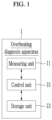
- FIG. 1 is a block diagram illustrating an overheating diagnosis apparatus according to an embodiment.
- an overheating diagnosis apparatus 1 includes a measuring unit 11, a storage unit 13, and a control unit 15.
- the measuring unit 11 may measure a temperature of an object at each point (hereinafter referred to as diagnosis point) at which overheating of the object is diagnosed and transmit a measurement result to the control unit 15.
- diagnosis point a point at which overheating of the object is diagnosed
- the measuring unit 11 may include a temperature sensor that measures the temperature of the object.
- the object may include, but is not limited to, a battery, and may include various devices that need to be predicted in advance before an overheating event occurs.
- the storage unit 13 may store a temperature value of the object measured by the measuring unit 11 at each diagnosis point.
- the storage unit 13 may store a moving average value MA, a standard deviation SD, a standard deviation average value SD_ave, and an overheating reference value Th that are calculated by the control unit 15 at each diagnosis point.
- a temperature value T, the moving average value MA, the standard deviation SD, the standard deviation average value SD_ave, and the overheating reference value Th of the object corresponding to a certain diagnosis point may be stored in the storage unit 13 in the form of a lookup table.
- the control unit 15 calculates the moving average value MA and the overheating reference value Th that has a predetermined value greater than the moving average value.
- the diagnosis point may be a point when charging of the battery starts or a point when discharging of the battery ends.
- the diagnosis point is not limited thereto, and may be variously set.
- the control unit 15 may extract a plurality of diagnosis points included in the preset number of samples SN to determine a sample group.
- the number of samples SN is the number of diagnosis points included in the sample group, and may be determined as the optimal number based on experiments, etc.
- the sample group is a subgroup of a plurality of past diagnosis points, which is a population, and may be a group for calculating the moving average value MA and the standard deviation average value SD_ave, etc., which will be described below.
- Table 1 Diagnosis cycle 1 ...
- Table 1 above shows an example of a lookup table for the temperature value T, the moving average value MA, the standard deviation SD, the standard deviation average value SD_ave, an error value ER, the overheating reference value Th, etc.
- a method of calculating an overheating reference value Th N required for overheating diagnosis at an N-th diagnosis point will be described in detail.
- the number of samples SN is assumed to be 5. However, the number of samples SN is not limited thereto, and may be determined as various positive integers.
- first diagnosis point 1 in Table 1 there is no previous diagnosis point to constitute the sample group, so the moving average value MA, the standard deviation SD, the standard deviation average value SD_ave, and the overheating reference value Th may be difficult to calculate directly (therefore, the corresponding values in Table 1 are blank).
- predetermined diagnosis points e.g. 2, 3, 4, and 5 adjacent to the first diagnosis point 1, it may be difficult to calculate the moving average value MA, the standard deviation SD, the standard deviation average value SD_ave, and the overheating reference value Th.
- a designer may provide values calculated on average according to the experiment to the moving average value MA, the standard deviation SD, the standard deviation average value SD_ave, and the overheating reference value Th at the initial diagnosis point and adjacent diagnosis points (e.g., 1, 2, 3, 4, and 5).
- control unit 15 may extract an N-1-th diagnosis point, an N-2-th diagnosis point, an N-3-th diagnosis point, an N-4-th diagnosis point, and an N-5-th diagnosis point corresponding to 5, which is the number of samples SN, to determine a sample group.
- the object is the battery
- an internal resistance value increases due to aging, and the temperature may gradually rise as the internal resistance value increases.
- Th N the overheating reference value
- the control unit 15 compares a temperature value T N measured at the N-th diagnosis point with the overheating reference value Th N calculated at the N-th diagnosis point to diagnose whether the object is overheated.
- a moving average value MA N and a standard deviation average value SD N_ ave are values required to calculate the overheating reference value Th N .
- the standard deviation SD N is not a value required when diagnosing an overheating condition at the N-th diagnosis point, but is necessary for determining overheating events at subsequent diagnosis points N+1, N+2, ..., and therefore, may be calculated and stored in the storage unit 13.
- MA N T N ⁇ 5 + T N ⁇ 4 + T N ⁇ 3 + T N ⁇ 2 + T N ⁇ 1 N
- the standard deviation SD N corresponding to the N-th diagnosis point is not a value necessary when diagnosing the overheating condition at the N-th diagnosis point, but is necessary when diagnosing whether the overheating event of the object has occurred at the subsequent diagnosis points N+1, N+2, ...
- the standard deviation SD N corresponding to the N-th diagnosis point may be calculated at the N-th diagnosis point and stored in the storage unit 13.
- control unit 15 may calculate the standard deviation average value SD N_ ave (0.07442) corresponding to the N-th diagnosis point based on a plurality of standard deviations SD N-5 , SD N-4 , SD N-3 , SD N-2 , and SD N-1 corresponding to each of the plurality of diagnosis points N-5, N-4, N-3, N-2, and N-1 belonging to the sample group.
- the control unit 15 may calculate the overheating reference value Th N that is a predetermined value larger than the moving average value MA N .
- the control unit 15 may calculate the error value ER N by multiplying the standard deviation average value SD N_ ave by a preset multiple ⁇ according to Equation 2 below.
- the multiple ⁇ is a value to reflect various errors, and may be determined as various values through the experiment.
- ER N SD N _ ave ⁇ ⁇
- control unit 15 may calculate the error value ER N , 0.22326 by multiplying the standard deviation average value SD N_ ave (0.07442) by the multiple ⁇ , 3.
- the error value ER N is a value that reflects errors that may occur in various situations, such as temperature measurement.
- an interval between the moving average value MA N and the overheating reference value Th N may be very narrow. That is, even if no actual overheating event occurred, the misdiagnosis may occur that the overheating event occurs according to an arithmetic calculation in which the temperature value T N measured at the N-th diagnosis point exceeds the overheating reference value Th N calculated at the N-th diagnosis point.
- the error value ER N which is the basis for calculating the overheating reference value Th N , is smaller than the generally expected value, there is a high possibility of misdiagnosis.
- the control unit 15 may calculate the overheating reference value Th N by adding the error value ER N to the moving average value MA N .
- the control unit 15 when the error value ER N is less than the error reference value TH N_ ER, the control unit 15 corrects the temperature value T corresponding to each of the plurality of diagnosis points N-5, N-4, N-3, N-2, and N-1 belonging to the sample group. That is, the control unit 15 may correct temperature data corresponding to each of the plurality of diagnosis points N-5, N-4, N-3, N-2, and N-1 belonging to the sample group.
- the control unit 15 may correct the temperature value T by adding a predetermined correction value ⁇ to the temperature value T when the temperature value T corresponding to each of the plurality of diagnosis points N-5, N-4, N-3, N-2, and N-1 is greater than or equal to the moving average value MA N .
- the temperature value T corresponding to each of the plurality of diagnosis points N-5, N-4, N-3, N-2, and N-1 is less than the moving average value MA N .
- the temperature value may be corrected by subtracting the correction value ⁇ from the temperature value T.
- the correction value ⁇ is assumed to be 2, but is not limited thereto and may be determined as various values.
- the error value ER N (0.22326) is smaller than the reference value TH N _ER (0.2938).
- the moving average value MA N is 29.38°C.
- corrected temperature values T' for each of the plurality of diagnosis points N-5, N-4, N-3, N-2, and N-1 may be 31.4°C, 27.3°C, 31.4°C, 27.3°C, and 31.5°C.
- the control unit 15 may again calculate a moving average value MA N ', a standard average deviation value SD N_ ave', and an error value ER N ' based on Equation 1, Equation 2, etc., based on the corrected temperature values T' 31.4°C, 27.3°C, 31.4°C, 27.3°C, and 31.5°C at each of the plurality of diagnosis points N-5, N-4, N-3, N-2, and N-1.
- control unit 15 may calculate the overheating reference value Th N by adding the error value ER N to the moving average value MA N according to Equation 3 below.
- Th N MA N + ER N
- the control unit 15 may calculate the overheating reference value Th N based on the moving average value MA N ' and the error value ER N ' calculated based on the corrected temperature value T' at each of the plurality of diagnosis points N-5, N-4, N-3, N-2, and N-1.
- the overheating reference value Th N calculated based on the corrected temperature value T' at each of the plurality of diagnosis points N-5, N-4, N-3, N-2, and N-1 is assumed to be 32.5°C.
- control unit 15 may compare the temperature T N value measured at the N-th diagnosis point and the overheating reference value Th N calculated at the N-th diagnosis point to diagnose whether the overheating event has occurred for the object.
- the control unit 15 may diagnose that no overheating event has occurred. That is, the control unit 15 may diagnose that the temperature of the object is in a normal state.
- FIG. 2 is a block diagram for describing a battery system according to another embodiment.
- a battery system 2 includes a battery 10, a relay 20, and a battery management system (BMS) 30.
- BMS battery management system
- the battery 10 may include a plurality of battery cells connected in series and/or in parallel. In FIG. 2 , three battery cells connected in parallel are illustrated, but the present disclosure is not limited thereto, and the battery 10 may include various numbers of battery cells connected in series and/or parallel. In some embodiments, the battery cell may be a rechargeable secondary battery.
- a predetermined number of battery cells are connected in parallel to form a battery bank, and a predetermined number of battery banks are connected in series to form a battery pack, so that desired power may be supplied to an external device.
- a predetermined number of battery cells are connected in parallel to form a battery bank, and a predetermined number of battery banks are connected in parallel to form a battery pack, so that desired power may be supplied to an external device.
- the present disclosure is not limited to this connection, and the battery 10 includes a plurality of battery banks including a plurality of battery cells connected in series and/or parallel, and the plurality of battery banks may also be connected in series and/or parallel.
- the battery 10 is connected between two output terminals OUT1 and OUT2 of the battery system 2.
- a relay 20 is connected between a positive electrode of the battery system 2 and the first output terminal OUT1.
- the relay 20 controls an electrical connection between the battery system 2 and the external device.
- the relay 20 When the relay 20 is turned on, the battery system 2 and the external device are electrically connected to perform the charge or discharge.
- the relay 20 When the relay 20 is turned off, the battery system 2 and the external device are electrically separated.
- the external device may be a charger in a charging cycle in which the battery 10 is charged by supplying power to the battery 10, and may be a load in a discharging cycle in which the battery 10 discharges power to the external device.
- the BMS 30 includes a measuring unit 31, a storage unit 33, and a control unit 35.
- the overheating diagnosis apparatus 1 illustrated in FIG. 1 may correspond to the BMS 30 illustrated in FIG. 2 .
- the functions performed by the measuring unit 11, the storage unit 13, and the control unit 15, respectively, of the overheating diagnosis apparatus 1 may correspond to functions performed by the measuring unit 31, the storage unit 33, and the control unit 35 of the BMS 30.
- the overheating diagnosis apparatus 1 may be configured separately from the battery system 2.
- the BMS 30 may perform the function of the overheating diagnosis apparatus 1.
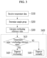
- FIG. 3 is a flowchart describing an overheating diagnosis method according to an embodiment.
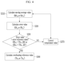
- FIG. 4 is a flowchart describing in detail an overheating reference value determination step (S300) of FIG. 3 .
- FIG. 5 is a flowchart describing in detail a temperature value correction step (S370) of FIG. 4 .
- an overheating diagnosis method, and an overheating diagnosis apparatus 1 and a battery system 2 that provide the method will be described.
- the measuring unit 31, the storage unit 33, and the control unit 35 of the BMS 30 will be described, which will be identically applied to the measuring unit 11, storage unit 13, and control unit 15 of the overheating diagnosis apparatus 1.
- the battery 10 is described, the present disclosure is not limited thereto, and may be identically applied to various objects that require temperature measurement.
- the control unit 35 receives temperature data including information on the measured temperature of the battery 10 from the measuring unit 31 at a predetermined diagnosis point at which the overheating of the battery 10 is diagnosed (S100).
- the measuring unit 31 may measure the temperature of the battery 10 and transmit the measured result to the control unit 35.
- the measuring unit 31 may include a temperature sensor to measure the temperature of the battery 10 at each diagnosis point and transmit the measured results to the control unit 35.
- the measuring unit 31 may receive a temperature value that is a result of the temperature sensor measuring the temperature of the battery 10 at predetermined time intervals or in real time, extract temperature data corresponding to a predetermined diagnosis point, and transmit the extracted temperature data to the control unit 35.
- control unit 35 extracts a plurality of previous diagnosis points corresponding to the number of samples SN based on a current diagnosis point N to determine a sample group (S200).
- control unit 35 may extract an N-5-th diagnosis point, an N-4-th diagnosis point, an N-3-th diagnosis point, an N-2-th diagnosis point, and an N-1-th diagnosis point corresponding to 5, which is the number of samples SN, to determine a sample group.
- control unit 35 calculates the overheating reference value Th N corresponding to the N-th diagnosis point based on the temperature values T N-5 , T N-4 , T N-3 , T N-2 , and T N-1 measured at each of the plurality of diagnosis points N-5, N-2, N-3, N-4, and N-1 belonging to the sample group (S300).
- step S300 the control unit 35 calculates a standard deviation average value SD N_ ave by averaging a plurality of standard deviations corresponding to each of the plurality of diagnosis points belonging to the sample group, and calculates an error value ER N based on the standard deviation average value SD N_ ave (S330).
- the control unit 35 may calculate the error value ER N by multiplying the standard deviation average value SD N_ ave by a preset multiple ⁇ according to Equation 2 above.
- the multiple ⁇ may be determined as various values through experiment.
- the control unit 35 may calculate the error value ER N , 0.22326 by multiplying the standard deviation average value SD N_ ave (0.07442) by the multiple ⁇ , 3.
- step S300 the control unit 35 compares the error value ER N with a predetermined error reference value TH N _ER (S350).
- step S300 when the error value ER N is smaller than the error reference value TH N_ ER, the control unit 35 corrects the temperature value T corresponding to each of the plurality of diagnosis points N-5, N-4, N-3, N-2, and N-1 belonging to the sample group.
- step S370 referring to FIG. 4 , the control unit 35 extracts the plurality of temperature values corresponding to each of the plurality of diagnosis points N-5, N-4, N-3, N-2, and N-1 belonging to the sample group (S371).
- step S370 the control unit 35 compares each of the plurality of temperature values with the moving average value MA N (S373).
- control unit 35 may determine whether the temperature value is greater than or equal to the moving average value MA N .
- step S370 when the temperature value is greater than or equal to the moving average value MA N as a result of the comparison (S372, YES), the control unit 35 corrects the temperature value by adding a predetermined correction value ⁇ to the temperature value (S373).
- step S370 when the temperature value is smaller than the moving average value MA N as a result of the comparison (S372, NO), the control unit 35 corrects the temperature value by subtracting the predetermined correction value ⁇ from the temperature value (S374).
- the control unit 35 may perform steps S310 and S330 again depending on corrected temperature values T' 31.4°C, 27.3°C, 31.4°C, 27.3°C, and 31.5°C at the plurality of diagnosis points N-5, N-4, N-3, N-2, and N-1 to calculate a corrected moving average value MA N ' and a corrected error value ER N ' again.
- the corrected error value ER N ' is greater than a corrected error reference value TH N_ ER' (S350, YES)
- the following step S390 may be performed. That is, steps S370, S310, and S330 may be repeated until the determination result of step S350 is YES.
- the corrected error reference value TH N_ ER' may be calculated as a value corresponding to 1% of the corrected moving average value MA N '.
- step S370 it is determined that the control unit 35 corrects all of the plurality of temperature values corresponding to each of the plurality of diagnosis points N-5, N-4, N-3, N-2, and N-1 belonging to the sample group (S375).
- step S370 when there is an uncorrected temperature value among the plurality of temperature values as a result of the determination (S375, NO), the control unit 35 repeats from step S372.
- step S370 when the correction is completed for all of the plurality of temperature values belonging to the sample group as a result of the determination (S375, YES), the control unit 35 may store, in the storage unit 32, a plurality of corrected temperature values T N-5 ', T N-4 ', T N-3 ', T N-2 ', and T N-1 ' corresponding to each of the plurality of diagnosis points N-5, N-4, N-3, N-2, and N-1, belonging to the sample group and complete the correction (S376).
- the measurement is performed at each of the plurality of diagnosis points N-5, N-4, N-3, N-2, and N-1, so the plurality of temperature values 29.4°C, 29.3°C, 29.4°C, 29.3°C, and 29.5°C already stored in the storage unit 32 may not be corrected. That is, at the N-th diagnosis point, even if the temperature value is corrected according to step S370, only the corrected overheating reference value Th N may be calculated based on the corrected moving average value MA N ' and the corrected error value ER N '.
- the temperature value is measured at each of the plurality of diagnosis points N-5, N-4, N-3, N-2, and N-1, so the plurality of temperature values 29.4°C, 29.3°C, 29.4°C, 29.3°C, and 29.5°C already stored in the storage unit 32 may change to the plurality of corrected temperature values 31.4°C, 27.3°C, 31.4°C, 27.3°C, and 31.5°C. Therefore, when calculating moving average values MA N+1 , MA N+2 , etc. and corrected error values ER N+1 + ER N+2 , etc., at N+1 diagnosis point, N+2 diagnosis point, etc., they may be calculated based on the plurality of temperature values corrected at the N-th diagnosis point.
- step S300 referring back to FIG. 4 , the control unit 35 calculates the overheating reference value Th N or Th N ' by adding the error value ER N or ER N ' to the moving average value MA N or MA N ' (S390).
- the control unit 35 may calculate the corrected overheating reference value Th N by adding the calculated corrected moving average value MA N ' and corrected error value ER N ' calculated based on the corrected temperature value T' of each of the plurality of diagnosis points N-5, N-4, N-3, N-2, and N-1.
- the corrected overheating reference value Th N ' calculated based on the corrected temperature value T' at each of the plurality of diagnosis points N-5, N-4, N-3, N-2, and N-1 is assumed to be 32.5°C.
- the control unit 35 diagnoses whether the overheating event has occurred in the battery 10 by comparing the temperature T N value measured at the N-th diagnosis point and the overheating reference value Th N (S400).
- step S400 the control unit 35 determines whether the temperature T N value measured at the N-th diagnosis point exceeds the overheating reference value Th N (S410).
- step S400 when the temperature T N value exceeds the overheating reference value Th N as a result of the determination (S410, Yes), the control unit 35 diagnoses that the overheating event has occurred in the battery 10 (S420).
- step S400 when the temperature T N value is less than or equal to the overheating reference value Th N as a result of the determination (S400, No), the control unit 35 diagnoses that the temperature of the battery 10 is in a normal state (S430).
- the control unit 35 may diagnose that no overheating event has occurred. That is, the control unit 35 may diagnose that the temperature of the object is in a normal state.
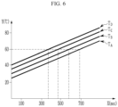
- FIG. 6 is an exemplary diagram illustrating a temperature change of a defect-free battery in a charging mode.
- FIG. 7 is an exemplary diagram illustrating a temperature change of a defective battery in the charging mode.
- an X-axis represents time (sec), and a Y-axis represents temperature (°C).
- FIG. 6 it is an exemplary diagram illustrating a temperature change over time when a defect-free battery is charged at various external temperatures.
- the temperature change of the battery 10 over time may correspond to a first graph T A .
- the temperature change of the battery 10 over time may correspond to a second graph T B .
- the temperature change of the battery 10 may correspond to a third graph T C and a fourth graph T D when the air temperature is 35°C and 40°C, respectively.
- a starting temperature value may be different when the external temperature changes, but as illustrated in FIG. 6 , the temperature change (i.e., slope) over time may be constant.
- FIG. 7 it is an exemplary diagram illustrating the temperature change over time when a defective battery is charged at a predetermined external temperature.
- a solid line FL is an actually measured temperature of the battery
- a dotted line DL drawn close to the solid line (FL) is a baseline.
- the baseline may be constructed by connecting the overheating reference values calculated at each diagnosis point according to the embodiment. Referring to FIGS. 6 and 7 , the temperature change of the defect-free battery may form a straight line graph as illustrated in FIG. 6 , but the temperature change of the defective battery may form a curved graph as illustrated in FIG. 7 .
- the occurrence of the overheating event is diagnosed at that point.
- the occurrence of the overheating event of the battery 10 may be diagnosed for the first time at a second point AD2.
- the occurrence of the overheating event may be diagnosed in advance before the temperature of the battery 10 exceeds the fixed overheating reference value (e.g., 60°C).
- the occurrence of the overheating event for the battery 10 is diagnosed for the first time at a first point AD1.
- the overheating event is continuously diagnosed at each diagnosis point from the first point AD1 at which the solid line FL exceeded the dotted line DL to the second point AD2.
- the experimental results showed a time difference (about 16 minutes) of about 1000 sec between the first point AD1 and the second point AD2.
- the occurrence of the overheating event of the battery 10 may be known in advance, which has the advantage of being able to prepare countermeasures.
Landscapes
- Engineering & Computer Science (AREA)
- Manufacturing & Machinery (AREA)
- Chemical & Material Sciences (AREA)
- Chemical Kinetics & Catalysis (AREA)
- Electrochemistry (AREA)
- General Chemical & Material Sciences (AREA)
- General Physics & Mathematics (AREA)
- Physics & Mathematics (AREA)
- Power Engineering (AREA)
- Microelectronics & Electronic Packaging (AREA)
- Life Sciences & Earth Sciences (AREA)
- Sustainable Development (AREA)
- Sustainable Energy (AREA)
- Transportation (AREA)
- Mechanical Engineering (AREA)
- Automation & Control Theory (AREA)
- Secondary Cells (AREA)
Abstract
Description
- This application claims priority to and the benefit of
Korean Patent Application No. 10-2022-0185631 filed in the Korean Intellectual Property Office on December 27, 2022 Korean Patent Application No. 10-2023-0185646 filed in the Korean Intellectual Property Office on December 19, 2023 - The present disclosure relates to a method of diagnosing overheating of an object (e.g., battery, etc.), and an overheating diagnosis apparatus and battery system providing the method.
- Recently, as the demand for portable electronic products such as a laptop, a video camera, and a portable phone, has rapidly increased, and as the development of electric vehicles, energy storage batteries, robots, and satellites begins in earnest, researches on high-performance batteries capable of repeated charging and discharging are actively underway.
- Currently commercialized batteries include a nickel cadmium battery, a nickel hydrogen battery, a nickel zinc battery, a lithium battery, etc. Among them, since the lithium batteries have little memory effect compared to the nickel-based batteries, the lithium batteries may be freely charged and discharged, have a very low self-discharge rate, and have high energy density, so they are in the spotlight.
- Meanwhile, a temperature of the battery is a factor that significantly affects performance of the battery. In general, the battery may operate efficiently when the temperature of the battery is distributed at an appropriate temperature. For example, when the temperature of the battery is too high, safety of an anode crystal lattice of the battery may decrease, which may lead to deterioration in the performance of the battery or accidents such as explosion. Therefore, it is necessary to accurately monitor the temperature of the battery.
- In the related art, the overheating of the battery was diagnosed by comparing the measured temperature of the battery with a preset reference value. In the related art method, a time interval between when an overheating event is diagnosed and when the explosion, etc., of the battery occurs is too short, making it difficult to take appropriate measures. In addition, the related art method has a problem of misdiagnosing an increase in temperature due to aging of the battery as an overheating event.
- The present disclosure attempts to provide an overheating diagnosis method capable of diagnosing abnormal heating behavior (hereinafter referred to as overheating) of an object with high precision, and an overheating diagnosis apparatus and battery system providing the method.
- According to an aspect of the present disclosure, an overheating diagnosis apparatus may include: a measuring unit configured to measure a temperature of an object, a storage unit configured to store a temperature value measured by the measuring unit, and a control unit configured to extract, at each diagnosis point at which overheating of the object is diagnosed, a plurality of previous diagnosis points corresponding to a predetermined number of samples based on a diagnosis point, calculate a moving average value which is an average of a plurality of temperature values corresponding to each of the plurality of previous diagnosis points, and calculate an standard deviation average value which is an average of a plurality of standard deviations corresponding to each of the plurality of previous diagnosis points. Further, when an error value calculated by multiplying the standard deviation average value by a predetermined multiple is greater than or equal to a predetermined error reference value, the control unit is further configured to calculate an overheating reference value by adding the error value to the moving average value, and diagnose an occurrence of an overheating event for the object by comparing the temperature value measured at each diagnosis point with the overheating reference value calculated at each diagnosis point.
- The control unit be further configured to correct the plurality of temperature values as a result of comparing each of the plurality of temperature values corresponding to the plurality of previous diagnosis points and the moving average value when the error value is less than the error reference value, and calculate the overheating reference value based on the plurality of corrected temperature values.
- The control unit may be configured to correct the temperature value by adding a predetermined correction value to the temperature value when the temperature value is greater than the moving average value and subtracting the correction value from the temperature value when the temperature value is less than the moving average value, for each of the plurality of temperature values.
- The control unit may be configured to, when the measured temperature value exceeds the overheating reference value diagnose that the overheating event has occurred in the object.
- According to another aspect of the present disclosure, a battery system may include a battery including a plurality of battery cells, a measuring unit configured to measure a temperature of the battery, a storage unit configured to store a temperature value measured by the measuring unit, and a control unit configured to extract, at each diagnosis point at which overheating of the battery is diagnosed, a plurality of previous diagnosis points corresponding to a predetermined number of samples based on the diagnosis point, calculate a moving average value which is an average of a plurality of temperature values corresponding to each of the plurality of previous diagnosis points, and calculate an standard deviation average value which is an average of a plurality of standard deviations corresponding to each of the plurality of previous diagnosis points, wherein when an error value calculated by multiplying the standard deviation average value by a predetermined multiple is greater than or equal to a predetermined error reference value, the control unit is further configured to calculate an overheating reference value by adding the error value to the moving average value, and diagnose an occurrence of an overheating event for the battery by comparing the temperature value measured at each diagnosis point with the overheating reference value calculated at each diagnosis point.
- The control unit may be further configured to correct the plurality of temperature values as a result of comparing each of the plurality of temperature values corresponding to the plurality of previous diagnosis points and the moving average value when the error value is less than the error reference value, and calculate the overheating reference value based on the plurality of corrected temperature values.
- The control unit may be configured to correct the temperature value by adding a predetermined correction value to the temperature value when the temperature value is greater than the moving average value and subtracting the predetermined correction value from the temperature value when the temperature value is less than the moving average value, for each of the plurality of temperature values.
- The control unit may be configured to, when the measured temperature value exceeds the overheating reference value, diagnose that the overheating event has occurred in the battery.
- According to still another aspect of the present disclosure, an overheating diagnosis method may include a temperature data collection step of receiving a temperature value, which is a temperature measurement value of a battery, from a measuring unit at a predetermined diagnosis point at which overheating of the battery including a plurality of battery cells is diagnosed, a sample group determination step of extracting a plurality of previous diagnosis points corresponding to the number of samples based on the diagnosis point, an overheating reference value calculation step including calculating a moving average value which is an average of a plurality of temperature values corresponding to each of the plurality of previous diagnosis points, calculating an standard deviation average value which is an average of a plurality of standard deviations corresponding to each of the plurality of previous diagnosis points, calculating an error value by multiplying the standard deviation average value by a predetermined multiple, and when the calculated error value is greater than or equal to a predetermined error reference value, calculating an overheating reference value by adding the error value to the moving average value, and an overheating diagnosis step of diagnosing an occurrence of an overheating event for the battery by comparing the temperature value with the overheating reference value.
- The overheating reference value calculation step may further includes, when the error value is less than the error reference value, a temperature value correction step of correcting the plurality of temperature values as a result of comparing each of the plurality of temperature values corresponding to the plurality of previous diagnosis points with the moving average value, and the overheating reference value may be calculated based on the plurality of corrected temperature values.
- The temperature value correction step may include extracting the plurality of temperature values corresponding to each of the plurality of previous diagnosis points, comparing each of the plurality of temperature values with the moving average value, a first correction step of correcting the temperature value by adding a predetermined correction value to the temperature value when the temperature value is greater than or equal to the moving average value as a result of the comparison, and a second correction step of correcting the temperature value by subtracting the predetermined correction value from the temperature value when the temperature value is less than the moving average value.
- The overheating diagnosis step may include comparing the measured temperature value and the overheating reference value, a first diagnosis step of diagnosing that the overheating event has occurred in the battery when the measured temperature value exceeds the overheating reference value as a result of the comparison, and a second diagnosis step of diagnosing the battery as a normal state in which no overheating event has occurred when the measured temperature value is less than or equal to the overheating reference value as a result of the comparison.
- Unlike the related art diagnosis method using a fixed reference value, according to the present disclosure, by calculating an overheating reference value that reflects a temperature trend for an object at each overheating diagnosis point and comparing the calculated overheating reference value with the measured temperature to perform the overheating diagnosis, it is possible to determine whether an overheating event occurs with high precision.
- According to the present disclosure, by calculating an overheating reference value based on the moving average value and the standard deviation at each diagnosis point, it is possible to prevent the problem of misdiagnosing an increase in temperature due to aging of an object (ex, battery, etc.) as an occurrence of an overheating event.
- According to the present disclosure, when the interval between the overheating reference value and the moving average value is significantly narrow, by correcting a plurality of temperature values that are the basis for calculating the overheating reference value, it is possible to remarkably improve the precision of the diagnosis.
-
-
FIG. 1 is a block diagram illustrating an overheating diagnosis apparatus according to an embodiment. -
FIG. 2 is a block diagram for describing a battery system according to another embodiment. -
FIG. 3 is a flowchart describing an overheating diagnosis method according to an embodiment. -
FIG. 4 is a flowchart describing in detail an overheating reference value determination step (S300) ofFIG. 3 . -
FIG. 5 is a flowchart describing in detail a temperature value correction step (S370) ofFIG. 4 . -
FIG. 6 is an exemplary diagram illustrating a temperature change of a defect-free battery in a charging mode. -
FIG. 7 is an exemplary diagram illustrating a temperature change of a defective battery in the charging mode. - Hereinafter, embodiments of the present disclosure will be described in detail with reference to the accompanying drawings and the same or similar components are given the same reference numerals and are not repeatedly described. The suffix "module" and/or "unit" for components used in the following description is given or mixed in consideration of only the ease of writing of the specification, and therefore, do not have meanings or roles that distinguish from each other in themselves. Further, when it is decided that a detailed description for the known art related to the present disclosure may obscure the gist of the present disclosure, the detailed description will be omitted. Further, it should be understood that the accompanying drawings are provided only in order to allow exemplary embodiments of the present disclosure to be easily understood, and the spirit of the present disclosure is not limited by the accompanying drawings, but includes all the modifications, equivalents, and substitutions included in the spirit and the scope of the present disclosure.
- Terms including an ordinal number such as first, second, etc., may be used to describe various components, but the components are not limited to these terms. The above terms are used solely for the purpose of distinguishing one component from another.
- Further, in the present specification, it is to be understood that when one component is referred to as being "connected to" or "coupled to" another component, it may be connected or coupled directly to another component or be connected to another component with the other component interposed therebetween. On the other hand, it should be understood that when one element is referred to as being "connected directly to" or "coupled directly to" another element, it may be connected to or coupled to another element without the other element interposed therebetween.
- It will be further understood that terms "include" or "have" used in the present specification specify the presence of features, numerals, steps, operations, components, parts mentioned in the present specification, or combinations thereof, but do not preclude the presence or addition of one or more other features, numerals, steps, operations, components, parts, or combinations thereof.
-
FIG. 1 is a block diagram illustrating an overheating diagnosis apparatus according to an embodiment. - Referring to
FIG. 1 , an overheating diagnosis apparatus 1 includes ameasuring unit 11, astorage unit 13, and acontrol unit 15. - The
measuring unit 11 may measure a temperature of an object at each point (hereinafter referred to as diagnosis point) at which overheating of the object is diagnosed and transmit a measurement result to thecontrol unit 15. For example, themeasuring unit 11 may include a temperature sensor that measures the temperature of the object. In this case, the object may include, but is not limited to, a battery, and may include various devices that need to be predicted in advance before an overheating event occurs. - The
storage unit 13 may store a temperature value of the object measured by themeasuring unit 11 at each diagnosis point. In addition, thestorage unit 13 may store a moving average value MA, a standard deviation SD, a standard deviation average value SD_ave, and an overheating reference value Th that are calculated by thecontrol unit 15 at each diagnosis point. For example, a temperature value T, the moving average value MA, the standard deviation SD, the standard deviation average value SD_ave, and the overheating reference value Th of the object corresponding to a certain diagnosis point may be stored in thestorage unit 13 in the form of a lookup table. - When the diagnosis point according to a preset condition arrives, the
control unit 15 calculates the moving average value MA and the overheating reference value Th that has a predetermined value greater than the moving average value. For example, when the object is a battery, the diagnosis point may be a point when charging of the battery starts or a point when discharging of the battery ends. However, the diagnosis point is not limited thereto, and may be variously set. - First, when counting diagnosis points in a direction of a previous diagnosis point based on a current diagnosis point N, the
control unit 15 may extract a plurality of diagnosis points included in the preset number of samples SN to determine a sample group. In this case, the number of samples SN is the number of diagnosis points included in the sample group, and may be determined as the optimal number based on experiments, etc. - The sample group is a subgroup of a plurality of past diagnosis points, which is a population, and may be a group for calculating the moving average value MA and the standard deviation average value SD_ave, etc., which will be described below.
(Table 1) Diagnosis cycle 1 ... N-5 N-4 N-3 N-2 N-1 N Temperature (T) - 29.4 29.3 29.4 29.3 29.5 TN Moving average(MA) - 29.37 29.36 29.35 29.37 29.36 MAN Standard deviation (SD) - 0.0745 0.0744 0.0743 0.0744 0.0745 SDN Standard deviation average (SD_ave) - 0.0740 0.0741 0.0740 0.0742 0.0742 SDN _ave Error value(ER) - 0.0766 0.0833 0.0866 0.1106 0.0466 ERN Overheating reference value(Th) - 29.6 29.61 29.61 29.702 29.50 ThN Diagnosis result - Normal Normal Normal Normal Normal - - Table 1 above shows an example of a lookup table for the temperature value T, the moving average value MA, the standard deviation SD, the standard deviation average value SD_ave, an error value ER, the overheating reference value Th, etc. Hereinafter, a method of calculating an overheating reference value ThN required for overheating diagnosis at an N-th diagnosis point will be described in detail. In addition, the number of samples SN is assumed to be 5. However, the number of samples SN is not limited thereto, and may be determined as various positive integers.
- For reference, at first diagnosis point 1 in Table 1, there is no previous diagnosis point to constitute the sample group, so the moving average value MA, the standard deviation SD, the standard deviation average value SD_ave, and the overheating reference value Th may be difficult to calculate directly (therefore, the corresponding values in Table 1 are blank). In addition, since the number of previous diagnosis points to constitute the sample group is insufficient at predetermined diagnosis points (e.g., 2, 3, 4, and 5) adjacent to the first diagnosis point 1, it may be difficult to calculate the moving average value MA, the standard deviation SD, the standard deviation average value SD_ave, and the overheating reference value Th. In this case, a designer may provide values calculated on average according to the experiment to the moving average value MA, the standard deviation SD, the standard deviation average value SD_ave, and the overheating reference value Th at the initial diagnosis point and adjacent diagnosis points (e.g., 1, 2, 3, 4, and 5).
- When counting the diagnosis points in the previous direction based on the N-th diagnosis point N which is the current diagnosis point, the
control unit 15 may extract an N-1-th diagnosis point, an N-2-th diagnosis point, an N-3-th diagnosis point, an N-4-th diagnosis point, and an N-5-th diagnosis point corresponding to 5, which is the number of samples SN, to determine a sample group. - The
control unit 15 may extract a plurality of diagnosis points N-1, N-2, N-3, N-4, and N-5 to determine the sample group, and calculate the overheating reference value ThN used for the overheating diagnosis based on temperature values measured at each of the plurality of diagnosis points N-1, N-2, N-3, N-4, and N-5 belonging to the sample group. - For example, when the object is the battery, if the battery is used for a long period of time, an internal resistance value increases due to aging, and the temperature may gradually rise as the internal resistance value increases. According to the embodiment, when the overheating of the battery is diagnosed based on the overheating reference value ThN, it is possible to prevent the problem of misdiagnosing the temperature rise due to long-term use as the occurrence of the overheating event. In addition, it may solve the problem of misdiagnosing a temporary temperature rise as the occurrence of the overheating event.
- Next, the
control unit 15 calculates the overheating reference value ThN corresponding to the N-th diagnosis point based on the temperature value T measured at each of the plurality of diagnosis points N-1, N-2, N-3, N-4, and N-5 belonging to the sample group. - According to an embodiment, the
control unit 15 compares a temperature value TN measured at the N-th diagnosis point with the overheating reference value ThN calculated at the N-th diagnosis point to diagnose whether the object is overheated. For example, referring to Table 1, a moving average value MAN and a standard deviation average value SDN_ave are values required to calculate the overheating reference value ThN. The standard deviation SDN is not a value required when diagnosing an overheating condition at the N-th diagnosis point, but is necessary for determining overheating events at subsequent diagnosis points N+1, N+2, ..., and therefore, may be calculated and stored in thestorage unit 13. - Hereinafter, referring to Table 1, the moving average value MAN, the standard deviation SDN, the standard deviation average value SDN_ave, an error value ERN, and the overheating reference value ThN calculated by the
control unit 15 at the N-th diagnosis point will be described. - The
control unit 15 may average (29.4°C + 29.3°C + 29.4°C + 29.3°C +29.5°C/5 = 29.38°C) a plurality of temperature values 29.4°C, 29.3°C, 29.4°C, 29.3°C, and 29.5°C corresponding to each of the plurality of diagnosis points N-5, N-4, N-3, N-2, and N-1 belonging to the sample group to calculate the moving average value MAN (29.38°C) corresponding to the N-th diagnosis point N. That is, the moving average value MAN at the N-th diagnosis point may be calculated by the following Equation 1.
- Referring to Table 1 above and Table 2 below, the
control unit 15 may calculate the standard deviation SDN corresponding to the N-th diagnosis point based on the temperature value T corresponding to each of the plurality of diagnosis points N-5, N-4, N-3, N-2, and N-1 belonging to the sample group and the moving average value MAN corresponding to the N-th diagnosis point N.(Table 2) N-5 N-4 N-3 N-2 N-1 N Temperature (T) 29.4 29.3 29.4 29.3 29.5 |T - MAN| |29.4-29.38| |29.3-29.38| |29.4-29.38| |29.3-29.38| |29.5-29.38| (T - MAN)2 (0.02)2 = 0.0004 (0.08)2 = 0.0064 (0.02)2 = 0.0004 (0.08)2 = 0.0064 (0.12)2 = 0.0144 Variance (0.0004+ 0.0064+ 0.0004+ 0.0064+ 0.0144)/5 = 0.0056 Standard deviation (SDN) 
0.0748 - As described above, the standard deviation SDN corresponding to the N-th diagnosis point is not a value necessary when diagnosing the overheating condition at the N-th diagnosis point, but is necessary when diagnosing whether the overheating event of the object has occurred at the subsequent diagnosis points N+1, N+2, ...
- Accordingly, the standard deviation SDN corresponding to the N-th diagnosis point may be calculated at the N-th diagnosis point and stored in the
storage unit 13.(Table 3) N-5 N-4 N-3 N-2 N-1 N Standard deviation(SD) 0.0745 0.0744 0.0743 0.0744 0.0745 Standard deviation average (SDN_ave) (0.0745+ 0.0744+ 0.0743+ 0,0744+ 0.0745)/5 = 0.07442 0,07442 - Referring to Tables 1 and 3 above, the
control unit 15 may calculate the standard deviation average value SDN_ave (0.07442) corresponding to the N-th diagnosis point based on a plurality of standard deviations SDN-5, SDN-4, SDN-3, SDN-2, and SDN-1 corresponding to each of the plurality of diagnosis points N-5, N-4, N-3, N-2, and N-1 belonging to the sample group. - The
control unit 15 may calculate the overheating reference value ThN that is a predetermined value larger than the moving average value MAN. First, thecontrol unit 15 may calculate the error value ERN by multiplying the standard deviation average value SDN_ave by a preset multiple α according toEquation 2 below. In this case, the multiple α is a value to reflect various errors, and may be determined as various values through the experiment. Hereinafter, the multiple α is assumed to be a natural number 3 (α=3).
- For example, referring to Table 3 and
Equation 2, thecontrol unit 15 may calculate the error value ERN, 0.22326 by multiplying the standard deviation average value SDN_ave (0.07442) by the multiple α, 3. - The error value ERN is a value that reflects errors that may occur in various situations, such as temperature measurement. When the error value ERN is very small, an interval between the moving average value MAN and the overheating reference value ThN may be very narrow. That is, even if no actual overheating event occurred, the misdiagnosis may occur that the overheating event occurs according to an arithmetic calculation in which the temperature value TN measured at the N-th diagnosis point exceeds the overheating reference value ThN calculated at the N-th diagnosis point. In other words, when the error value ERN, which is the basis for calculating the overheating reference value ThN, is smaller than the generally expected value, there is a high possibility of misdiagnosis.
- According to an embodiment, when the error value ERN is greater than or equal to a predetermined error reference value THN_ER, the
control unit 15 may calculate the overheating reference value ThN by adding the error value ERN to the moving average value MAN. Hereinafter, the error reference value THN_ER is assumed to be a value (29.38°C × 0.01 = 0.2938) corresponding to 1% of the moving average value MAN, but is not limited thereto and may be determined as various values. - According to another embodiment, when the error value ERN is less than the error reference value THN_ER, the
control unit 15 corrects the temperature value T corresponding to each of the plurality of diagnosis points N-5, N-4, N-3, N-2, and N-1 belonging to the sample group. That is, thecontrol unit 15 may correct temperature data corresponding to each of the plurality of diagnosis points N-5, N-4, N-3, N-2, and N-1 belonging to the sample group. - According to another embodiment, the
control unit 15 may correct the temperature value T by adding a predetermined correction value β to the temperature value T when the temperature value T corresponding to each of the plurality of diagnosis points N-5, N-4, N-3, N-2, and N-1 is greater than or equal to the moving average value MAN. When the temperature value T corresponding to each of the plurality of diagnosis points N-5, N-4, N-3, N-2, and N-1 is less than the moving average value MAN, the temperature value may be corrected by subtracting the correction value β from the temperature value T. Hereinafter, the correction value β is assumed to be 2, but is not limited thereto and may be determined as various values. - Referring to
Equation 2 above, the error value ERN (0.22326) is smaller than the reference value THN_ER (0.2938). Thecontrol unit 15 may correct the plurality of temperature values 29.4°C, 29.3°C, 29.4°C, 29.3°C, and 29.5°C belonging to the sample group by calculating ± correction value β =2 for each of the plurality of temperature values 29.4°C, 29.3°C, 29.4°C, 29.3°C, and 29.5°C corresponding to the plurality of diagnosis points N-5, N-4, N-3, N-2, and N-1 belonging to the sample group. - According to Equation 1, the moving average value MAN is 29.38°C. Specifically, since a temperature value TN-5 (29.4°C) at the N-5-th diagnosis point is greater than or equal to the moving average value MAN (29.38°C), the
control unit 15 may calculate a temperature value TN-5 of 29.4 + 2 = 31.4°C at the processed N-5-th diagnosis point by adding the correction value β = 2 to the temperature value TN-5 (29.4°C) at the N-5th diagnosis point. Since the temperature value TN-4 (29.3°C) at the N-4-th diagnosis point is smaller than the moving average value MAN of 29.38°C, thecontrol unit 15 may calculate the temperature value TN-4 (29.3 - 2 = 27.3°C) by subtracting the correction value β = 2 from the temperature value TN-4 (29.3°C) at the N-4-th diagnosis point. When correcting the temperature values 29.4°C, 29.3°C, and 29.5°C at the N-3-th diagnosis point, the N-2-th diagnosis point, and the N-1-th diagnosis point (N-3, N-2, and N-1), respectively, corrected temperature values T' for each of the plurality of diagnosis points N-5, N-4, N-3, N-2, and N-1 may be 31.4°C, 27.3°C, 31.4°C, 27.3°C, and 31.5°C. - When the temperature values at each of the plurality of diagnosis points N-5, N-4, N-3, N-2, and N-1 are corrected, the
control unit 15 may again calculate a moving average value MAN', a standard average deviation value SDN_ave', and an error value ERN' based on Equation 1,Equation 2, etc., based on the corrected temperature values T' 31.4°C, 27.3°C, 31.4°C, 27.3°C, and 31.5°C at each of the plurality of diagnosis points N-5, N-4, N-3, N-2, and N-1. - Next, the
control unit 15 may calculate the overheating reference value ThN by adding the error value ERN to the moving average value MAN according to Equation 3 below.
- For example, when the temperature value T at each of the plurality of diagnosis points N-5, N-4, N-3, N-2, and N-1 is corrected, the
control unit 15 may calculate the overheating reference value ThN based on the moving average value MAN' and the error value ERN' calculated based on the corrected temperature value T' at each of the plurality of diagnosis points N-5, N-4, N-3, N-2, and N-1. For example, the overheating reference value ThN calculated based on the corrected temperature value T' at each of the plurality of diagnosis points N-5, N-4, N-3, N-2, and N-1 is assumed to be 32.5°C. - Next, the
control unit 15 may compare the temperature TN value measured at the N-th diagnosis point and the overheating reference value ThN calculated at the N-th diagnosis point to diagnose whether the overheating event has occurred for the object. - For example, referring to Table 1, assume that the temperature TN value measured at the N-th diagnosis point is 30°C. Since the temperature TN value (30°C) corresponding to the N-th diagnosis point is smaller than the overheating reference value ThN (32.5°C) corresponding to the N-th diagnosis point, the
control unit 15 may diagnose that no overheating event has occurred. That is, thecontrol unit 15 may diagnose that the temperature of the object is in a normal state. -
FIG. 2 is a block diagram for describing a battery system according to another embodiment. - Referring to
FIG. 2 , abattery system 2 includes abattery 10, arelay 20, and a battery management system (BMS) 30. - The
battery 10 may include a plurality of battery cells connected in series and/or in parallel. InFIG. 2 , three battery cells connected in parallel are illustrated, but the present disclosure is not limited thereto, and thebattery 10 may include various numbers of battery cells connected in series and/or parallel. In some embodiments, the battery cell may be a rechargeable secondary battery. - In addition, for example, in the
battery 10, a predetermined number of battery cells are connected in parallel to form a battery bank, and a predetermined number of battery banks are connected in series to form a battery pack, so that desired power may be supplied to an external device. As another example, in thebattery 10, a predetermined number of battery cells are connected in parallel to form a battery bank, and a predetermined number of battery banks are connected in parallel to form a battery pack, so that desired power may be supplied to an external device. However, the present disclosure is not limited to this connection, and thebattery 10 includes a plurality of battery banks including a plurality of battery cells connected in series and/or parallel, and the plurality of battery banks may also be connected in series and/or parallel. - In
FIG. 2 , thebattery 10 is connected between two output terminals OUT1 and OUT2 of thebattery system 2. In addition, arelay 20 is connected between a positive electrode of thebattery system 2 and the first output terminal OUT1. The configurations illustrated inFIG. 2 and the connection relationship between the configurations are examples, and the present disclosure is not limited thereto. - The
relay 20 controls an electrical connection between thebattery system 2 and the external device. When therelay 20 is turned on, thebattery system 2 and the external device are electrically connected to perform the charge or discharge. When therelay 20 is turned off, thebattery system 2 and the external device are electrically separated. In this case, the external device may be a charger in a charging cycle in which thebattery 10 is charged by supplying power to thebattery 10, and may be a load in a discharging cycle in which thebattery 10 discharges power to the external device. - The
BMS 30 includes a measuringunit 31, astorage unit 33, and acontrol unit 35. The overheating diagnosis apparatus 1 illustrated inFIG. 1 may correspond to theBMS 30 illustrated inFIG. 2 . Describing in detail, the functions performed by the measuringunit 11, thestorage unit 13, and thecontrol unit 15, respectively, of the overheating diagnosis apparatus 1 may correspond to functions performed by the measuringunit 31, thestorage unit 33, and thecontrol unit 35 of theBMS 30. For example, the overheating diagnosis apparatus 1 may be configured separately from thebattery system 2. As another example, in thebattery system 2 as illustrated inFIG. 2 , theBMS 30 may perform the function of the overheating diagnosis apparatus 1. - Hereinafter, descriptions of the functions of each of the measuring
unit 31, thestorage unit 33, and thecontrol unit 35 of theBMS 30 will be replaced with descriptions of the functions of the measuringunit 11, thestorage unit 13, and thecontrol unit 15, respectively, of the overheating diagnosis apparatus 1. -
FIG. 3 is a flowchart describing an overheating diagnosis method according to an embodiment.FIG. 4 is a flowchart describing in detail an overheating reference value determination step (S300) ofFIG. 3 .FIG. 5 is a flowchart describing in detail a temperature value correction step (S370) ofFIG. 4 . - Hereinafter, referring to
FIGS. 1 to 5 , an overheating diagnosis method, and an overheating diagnosis apparatus 1 and abattery system 2 that provide the method will be described. Hereinafter, the measuringunit 31, thestorage unit 33, and thecontrol unit 35 of theBMS 30 will be described, which will be identically applied to the measuringunit 11,storage unit 13, andcontrol unit 15 of the overheating diagnosis apparatus 1. In addition, although thebattery 10 is described, the present disclosure is not limited thereto, and may be identically applied to various objects that require temperature measurement. - First, the
control unit 35 receives temperature data including information on the measured temperature of thebattery 10 from the measuringunit 31 at a predetermined diagnosis point at which the overheating of thebattery 10 is diagnosed (S100). When diagnosis points according to preset conditions arrive, the measuringunit 31 may measure the temperature of thebattery 10 and transmit the measured result to thecontrol unit 35. For example, the measuringunit 31 may include a temperature sensor to measure the temperature of thebattery 10 at each diagnosis point and transmit the measured results to thecontrol unit 35. As another example, the measuringunit 31 may receive a temperature value that is a result of the temperature sensor measuring the temperature of thebattery 10 at predetermined time intervals or in real time, extract temperature data corresponding to a predetermined diagnosis point, and transmit the extracted temperature data to thecontrol unit 35. - Next, the
control unit 35 extracts a plurality of previous diagnosis points corresponding to the number of samples SN based on a current diagnosis point N to determine a sample group (S200). - Referring to Table 1, when counting the diagnosis points in the previous direction based on an N-th diagnosis point N which is the current diagnosis point, the
control unit 35 may extract an N-5-th diagnosis point, an N-4-th diagnosis point, an N-3-th diagnosis point, an N-2-th diagnosis point, and an N-1-th diagnosis point corresponding to 5, which is the number of samples SN, to determine a sample group. - The
control unit 35 may extract a plurality of diagnosis points N-5, N-4, N-3, N-2, and N-1 to determine a sample group, and calculate an overheating reference value ThN used for diagnosis based on temperature values TN-5, TN-4, TN-3, TN-2, and TN-1 measured at each of the plurality of diagnosis points N-5, N-4, N-3, N-2, and N-1 belonging to the sample group. By calculating the overheating reference value ThN using the method described below, it is possible to prevent the problem of misdiagnosing a temperature increase due to aging of the battery as the occurrence of an overheating event. In addition, it may solve the problem of misdiagnosing a temporary temperature rise due to various causes as the occurrence of the overheating event. - Next, the
control unit 35 calculates the overheating reference value ThN corresponding to the N-th diagnosis point based on the temperature values TN-5, TN-4, TN-3, TN-2, and TN-1 measured at each of the plurality of diagnosis points N-5, N-2, N-3, N-4, and N-1 belonging to the sample group (S300). - In step S300, referring to
FIG. 4 , thecontrol unit 35 calculates a moving average value MAN corresponding to the N-th diagnosis point by averaging the plurality of temperature values corresponding to each of the plurality of diagnosis points belonging to the sample group. (S310). - Specifically, referring to Table 1, the
control unit 35 may average (29.4°C + 29.3°C + 29.4°C + 29.3°C +29.5°C/5 = 29.38°C) a plurality of temperature values 29.4°C, 29.3°C, 29.4°C, 29.3°C, and 29.5°C corresponding to each of the plurality of diagnosis points N-5, N-4, N-3, N-2, and N-1 belonging to the sample group to calculate the moving average value MAN (29.38°C) corresponding to the N-th diagnosis point N. - In step S300, the
control unit 35 calculates a standard deviation average value SDN_ave by averaging a plurality of standard deviations corresponding to each of the plurality of diagnosis points belonging to the sample group, and calculates an error value ERN based on the standard deviation average value SDN_ave (S330). - Specifically, referring to Table 3, the
control unit 35 may calculate the standard deviation average value SDN_ave (0.07442) corresponding to the N-th diagnosis point based on a plurality of standard deviations SDN-5, SDN-4, SDN-3, SDN-2, and SDN-1 corresponding to each of the plurality of diagnosis points N-5, N-4, N-3, N-2, and N-1 belonging to the sample group. - The
control unit 35 may calculate the error value ERN by multiplying the standard deviation average value SDN_ave by a preset multiple α according toEquation 2 above. In this case, the multiple α may be determined as various values through experiment. Hereinafter, the multiple α is assumed to be a natural number 3 (α=3). For example, referring to Table 3 andEquation 2, thecontrol unit 35 may calculate the error value ERN, 0.22326 by multiplying the standard deviation average value SDN_ave (0.07442) by the multiple α, 3. - In step S300, the
control unit 35 compares the error value ERN with a predetermined error reference value THN_ER (S350). - The error value ERN is a value that reflects errors that may occur in various situations, such as temperature measurement. When the error value ERN is very small, an interval between the moving average value MAN and the overheating reference value Th may be very narrow. That is, even if no actual overheating event occurred, the misdiagnosis may occur that the overheating event occurs according to an arithmetic calculation in which the temperature TN value measured at the N-th diagnosis point exceeds the overheating reference value ThN calculated at the N-th diagnosis point. In other words, when the error value ER, which is the basis for calculating the overheating reference value Th, is smaller than the generally expected value, there is a high possibility of misdiagnosis.
- In step S300, when the error value ERN is smaller than the error reference value THN_ER, the
control unit 35 corrects the temperature value T corresponding to each of the plurality of diagnosis points N-5, N-4, N-3, N-2, and N-1 belonging to the sample group. - For example, the error reference value THN_ER may be calculated to be a value (29.38°C × 0.01 = 0.2938) corresponding to 1% of the moving average value MAN, but is not limited thereto and may be determined as various values.
- In step S370, referring to
FIG. 4 , thecontrol unit 35 extracts the plurality of temperature values corresponding to each of the plurality of diagnosis points N-5, N-4, N-3, N-2, and N-1 belonging to the sample group (S371). - In step S370, the
control unit 35 compares each of the plurality of temperature values with the moving average value MAN (S373). - For example, for each of the plurality of temperature values, the
control unit 35 may determine whether the temperature value is greater than or equal to the moving average value MAN. - In step S370, when the temperature value is greater than or equal to the moving average value MAN as a result of the comparison (S372, YES), the
control unit 35 corrects the temperature value by adding a predetermined correction value β to the temperature value (S373). - In step S370, when the temperature value is smaller than the moving average value MAN as a result of the comparison (S372, NO), the
control unit 35 corrects the temperature value by subtracting the predetermined correction value β from the temperature value (S374). - For example, referring to Table 1 above, the temperature value T may be corrected by adding the correction value β=2 to each of the temperature values 29.4°C, 29.4°C, and 29.5°C at the N-5-th diagnosis point, N-3-th diagnosis point, and N-1-th diagnosis point corresponding to the moving average value MAN (29.38°C) or greater among the the plurality of diagnosis points N-5, N-4, N-3, N-2, and N-1 belonging to the sample group. In addition, the temperature value T may be corrected by subtracting the correction value β=2 from each of the temperature values 29.3°C and 29.3°C at the N-4-th diagnosis point and the N-2-th diagnosis point, corresponding to less than the moving average value MAN (29.38°C) among the the plurality of diagnosis points N-5, N-4, N-3, N-2, and N-1 belonging to the sample group. Then, the temperature values 29.4°C, 29.3°C, 29.4°C, 29.3°C, and 29.5°C at each of the plurality of diagnosis points N-5, N-4, N-3, N-2, and N-1 may be corrected to 31.4°C, 27.3°C, 31.4°C, 27.3°C, and 31.5°C.
- Referring to
FIGS. 4 and5 , thecontrol unit 35 may perform steps S310 and S330 again depending on corrected temperature values T' 31.4°C, 27.3°C, 31.4°C, 27.3°C, and 31.5°C at the plurality of diagnosis points N-5, N-4, N-3, N-2, and N-1 to calculate a corrected moving average value MAN' and a corrected error value ERN' again. As a result of the determination in step S350, when the corrected error value ERN' is greater than a corrected error reference value THN_ER' (S350, YES), the following step S390 may be performed. That is, steps S370, S310, and S330 may be repeated until the determination result of step S350 is YES. In this case, the corrected error reference value THN_ER' may be calculated as a value corresponding to 1% of the corrected moving average value MAN'. - In step S370, it is determined that the
control unit 35 corrects all of the plurality of temperature values corresponding to each of the plurality of diagnosis points N-5, N-4, N-3, N-2, and N-1 belonging to the sample group (S375). - In step S370, when there is an uncorrected temperature value among the plurality of temperature values as a result of the determination (S375, NO), the
control unit 35 repeats from step S372. - In step S370, when the correction is completed for all of the plurality of temperature values belonging to the sample group as a result of the determination (S375, YES), the
control unit 35 may store, in the storage unit 32, a plurality of corrected temperature values TN-5', TN-4', TN-3', TN-2', and TN-1' corresponding to each of the plurality of diagnosis points N-5, N-4, N-3, N-2, and N-1, belonging to the sample group and complete the correction (S376). - According to an embodiment, at the N-th diagnosis point, even if the temperature value is corrected according to step S370, the measurement is performed at each of the plurality of diagnosis points N-5, N-4, N-3, N-2, and N-1, so the plurality of temperature values 29.4°C, 29.3°C, 29.4°C, 29.3°C, and 29.5°C already stored in the storage unit 32 may not be corrected. That is, at the N-th diagnosis point, even if the temperature value is corrected according to step S370, only the corrected overheating reference value ThN may be calculated based on the corrected moving average value MAN' and the corrected error value ERN'.
- According to another embodiment, at the N-th diagnosis point, even if the temperature value is corrected according to step S370, the temperature value is measured at each of the plurality of diagnosis points N-5, N-4, N-3, N-2, and N-1, so the plurality of temperature values 29.4°C, 29.3°C, 29.4°C, 29.3°C, and 29.5°C already stored in the storage unit 32 may change to the plurality of corrected temperature values 31.4°C, 27.3°C, 31.4°C, 27.3°C, and 31.5°C. Therefore, when calculating moving average values MAN+1, MAN+2, etc. and corrected error values ERN+1 + ERN+2, etc., at N+1 diagnosis point, N+2 diagnosis point, etc., they may be calculated based on the plurality of temperature values corrected at the N-th diagnosis point.
- In step S300, referring back to
FIG. 4 , thecontrol unit 35 calculates the overheating reference value ThN or ThN' by adding the error value ERN or ERN' to the moving average value MAN or MAN' (S390). - For example, when the temperature value T of each of the plurality of diagnosis points N-5, N-4, N-3, N-2, and N-1 is corrected, the
control unit 35 may calculate the corrected overheating reference value ThN by adding the calculated corrected moving average value MAN' and corrected error value ERN' calculated based on the corrected temperature value T' of each of the plurality of diagnosis points N-5, N-4, N-3, N-2, and N-1. For example, the corrected overheating reference value ThN' calculated based on the corrected temperature value T' at each of the plurality of diagnosis points N-5, N-4, N-3, N-2, and N-1 is assumed to be 32.5°C. - Next, referring back to
FIG. 3 , thecontrol unit 35 diagnoses whether the overheating event has occurred in thebattery 10 by comparing the temperature TN value measured at the N-th diagnosis point and the overheating reference value ThN (S400). - In step S400, the
control unit 35 determines whether the temperature TN value measured at the N-th diagnosis point exceeds the overheating reference value ThN (S410). - In step S400, when the temperature TN value exceeds the overheating reference value ThN as a result of the determination (S410, Yes), the
control unit 35 diagnoses that the overheating event has occurred in the battery 10 (S420). - In step S400, when the temperature TN value is less than or equal to the overheating reference value ThN as a result of the determination (S400, No), the
control unit 35 diagnoses that the temperature of thebattery 10 is in a normal state (S430). - For example, referring to Table 1, assume that the temperature TN value measured at the N-th diagnosis point is 30°C. Since the temperature TN value (30°C) corresponding to the N-th diagnosis point is smaller than the overheating reference value ThN (32.5°C) corresponding to the N-th diagnosis point, the
control unit 35 may diagnose that no overheating event has occurred. That is, thecontrol unit 35 may diagnose that the temperature of the object is in a normal state. -
FIG. 6 is an exemplary diagram illustrating a temperature change of a defect-free battery in a charging mode.FIG. 7 is an exemplary diagram illustrating a temperature change of a defective battery in the charging mode. - In
FIGS. 6 and7 , an X-axis represents time (sec), and a Y-axis represents temperature (°C). - Referring to
FIG. 6 , it is an exemplary diagram illustrating a temperature change over time when a defect-free battery is charged at various external temperatures. - For example, when air temperature is 25°C, in a charging mode in which the
battery 10 is charged with power from an external device, the temperature change of thebattery 10 over time may correspond to a first graph TA. As another example, when thebattery 10 is charged when the air temperature is 30°C, the temperature change of thebattery 10 over time may correspond to a second graph TB. Likewise, the temperature change of thebattery 10 may correspond to a third graph TC and a fourth graph TD when the air temperature is 35°C and 40°C, respectively. - That is, in the case of a
battery 10 in a normal state according to a predetermined standard or anew battery 10 unused, a starting temperature value may be different when the external temperature changes, but as illustrated inFIG. 6 , the temperature change (i.e., slope) over time may be constant. - Referring to
FIG. 7 , it is an exemplary diagram illustrating the temperature change over time when a defective battery is charged at a predetermined external temperature. - In this case, a solid line FL is an actually measured temperature of the battery, and a dotted line DL drawn close to the solid line (FL) is a baseline. The baseline may be constructed by connecting the overheating reference values calculated at each diagnosis point according to the embodiment. Referring to
FIGS. 6 and7 , the temperature change of the defect-free battery may form a straight line graph as illustrated inFIG. 6 , but the temperature change of the defective battery may form a curved graph as illustrated inFIG. 7 . - Conventionally, when the temperature of the
battery 10 exceeds the fixed overheating reference value (for example, 60°C), the occurrence of the overheating event is diagnosed at that point. Referring toFIG. 7 , conventionally, the occurrence of the overheating event of thebattery 10 may be diagnosed for the first time at a second point AD2. - However, according to the overheating diagnosis method according to the embodiment, the occurrence of the overheating event may be diagnosed in advance before the temperature of the
battery 10 exceeds the fixed overheating reference value (e.g., 60°C). As a result of the experiment, the occurrence of the overheating event for thebattery 10 is diagnosed for the first time at a first point AD1. Specifically, as a result of the diagnosis, the overheating event is continuously diagnosed at each diagnosis point from the first point AD1 at which the solid line FL exceeded the dotted line DL to the second point AD2. - Referring to
FIG. 7 , the experimental results showed a time difference (about 16 minutes) of about 1000 sec between the first point AD1 and the second point AD2. According to the overheating diagnosis method according to the embodiment, the occurrence of the overheating event of thebattery 10 may be known in advance, which has the advantage of being able to prepare countermeasures. - Although the embodiments of the present disclosure have been described in detail above, the scope of the present disclosure is not limited thereto, and various modifications and improvements by those of ordinary skill in the field to which the present disclosure pertains belong to the scope of the present disclosure.
Claims (12)
- An overheating diagnosis apparatus, comprising:a measuring unit configured to measure a temperature of an object;a storage unit configured to store a temperature value measured by the measuring unit; anda control unit configured to:extract, at each diagnosis point at which overheating of the object is diagnosed, a plurality of previous diagnosis points corresponding to a predetermined number of samples based on a diagnosis point,calculate a moving average value which is an average of a plurality of temperature values corresponding to each of the plurality of previous diagnosis points, andcalculate an standard deviation average value which is an average of a plurality of standard deviations corresponding to each of the plurality of previous diagnosis points,wherein when an error value calculated by multiplying the standard deviation average value by a predetermined multiple is greater than or equal to a predetermined error reference value, the control unit is further configured to:calculate an overheating reference value by adding the error value to the moving average value, anddiagnose an occurrence of an overheating event for the object by comparing the temperature value measured at each diagnosis point with the overheating reference value calculated at each diagnosis point.
- The overheating diagnosis apparatus of claim 1, wherein the control unit is further configured to:correct the plurality of temperature values as a result of comparing each of the plurality of temperature values corresponding to the plurality of previous diagnosis points and the moving average value when the error value is less than the error reference value, andcalculate the overheating reference value based on the plurality of corrected temperature values.
- The overheating diagnosis apparatus of claim 2, wherein the control unit is configured to correct the temperature value by adding a predetermined correction value to the temperature value when the temperature value is greater than the moving average value and subtracting the correction value from the temperature value when the temperature value is less than the moving average value, for each of the plurality of temperature values.
- The overheating diagnosis apparatus of claim 1, wherein when the measured temperature value exceeds the overheating reference value, the control unit is configured to diagnose that the overheating event has occurred in the object.
- A battery system, comprising:a battery including a plurality of battery cells;a measuring unit configured to measure a temperature of the battery;a storage unit configured to store a temperature value measured by the measuring unit; anda control unit configured to:extract, at each diagnosis point at which overheating of the battery is diagnosed, a plurality of previous diagnosis points corresponding to a predetermined number of samples based on the diagnosis point,calculate a moving average value which is an average of a plurality of temperature values corresponding to each of the plurality of previous diagnosis points, andcalculate an standard deviation average value which is an average of a plurality of standard deviations corresponding to each of the plurality of previous diagnosis points,wherein when an error value calculated by multiplying the standard deviation average value by a predetermined multiple is greater than or equal to a predetermined error reference value, the control unit is further configured to:calculate an overheating reference value by adding the error value to the moving average value, anddiagnose an occurrence of an overheating event for the battery by comparing the temperature value measured at each diagnosis point with the overheating reference value calculated at each diagnosis point.
- The battery system of claim 5, wherein the control unit is further configured to:correct the plurality of temperature values as a result of comparing each of the plurality of temperature values corresponding to the plurality of previous diagnosis points and the moving average value when the error value is less than the error reference value, andcalculate the overheating reference value based on the plurality of corrected temperature values.
- The battery system of claim 6, wherein the control unit is configured to correct the temperature value by adding a predetermined correction value to the temperature value when the temperature value is greater than the moving average value and subtracting the predetermined correction value from the temperature value when the temperature value is less than the moving average value, for each of the plurality of temperature values.
- The battery system of claim 5, wherein when the measured temperature value exceeds the overheating reference value, the control unit is configured to diagnoses that the overheating event has occurred in the battery.
- An overheating diagnosis method, comprising:a temperature data collection step of receiving a temperature value, which is a temperature measurement value of a battery, from a measuring unit at a predetermined diagnosis point at which overheating of the battery including a plurality of battery cells is diagnosed;a sample group determination step of extracting a plurality of previous diagnosis points corresponding to a number of samples based on the predetermined diagnosis point;an overheating reference value calculation step including:calculating a moving average value which is an average of a plurality of temperature values corresponding to each of the plurality of previous diagnosis points, calculating an standard deviation average value which is an average of a plurality of standard deviations corresponding to each of the plurality of previous diagnosis points,calculating an error value by multiplying the standard deviation average value by a predetermined multiple, andwhen the calculated error value is greater than or equal to a predetermined error reference value, calculating an overheating reference value by adding the error value to the moving average value; andan overheating diagnosis step of diagnosing an occurrence of an overheating event for the battery by comparing the temperature value with the overheating reference value.
- The overheating diagnosis method of claim 9, wherein the overheating reference value calculation step further includes: when the error value is less than the predetermined error reference value, a temperature value correction step of correcting the plurality of temperature values as a result of comparing each of the plurality of temperature values corresponding to the plurality of previous diagnosis points with the moving average value, and
wherein the overheating reference value is calculated based on the plurality of corrected temperature values. - The overheating diagnosis method of claim 10, wherein the temperature value correction step includes:extracting the plurality of temperature values corresponding to each of the plurality of previous diagnosis points;comparing each of the plurality of temperature values with the moving average value;a first correction step of correcting the temperature value by adding a predetermined correction value to the temperature value when the temperature value is greater than or equal to the moving average value as a result of the comparison; anda second correction step of correcting the temperature value by subtracting the predetermined correction value from the temperature value when the temperature value is less than the moving average value.
- The overheating diagnosis method of claim 9, wherein the overheating diagnosis step includes:comparing the measured temperature value and the overheating reference value;a first diagnosis step of diagnosing that the overheating event has occurred in the battery when the measured temperature value exceeds the overheating reference value as a result of the comparison; anda second diagnosis step of diagnosing the battery as a normal state in which no overheating event has occurred when the measured temperature value is less than or equal to the overheating reference value as a result of the comparison.
Applications Claiming Priority (3)
| Application Number | Priority Date | Filing Date | Title |
|---|---|---|---|
| KR20220185631 | 2022-12-27 | ||
| KR1020230185646A KR20240103994A (en) | 2022-12-27 | 2023-12-19 | Overheating diagnosis method, overheating diagnosis apparatus and battery ststem providing the same |
| PCT/KR2023/021634 WO2024144230A1 (en) | 2022-12-27 | 2023-12-26 | Overheating diagnosis method, and overheating diagnosis apparatus and battery system for providing same method |
Publications (2)
| Publication Number | Publication Date |
|---|---|
| EP4576321A1 true EP4576321A1 (en) | 2025-06-25 |
| EP4576321A4 EP4576321A4 (en) | 2026-03-25 |
Family
ID=91718427
Family Applications (1)
| Application Number | Title | Priority Date | Filing Date |
|---|---|---|---|
| EP23912905.9A Pending EP4576321A4 (en) | 2022-12-27 | 2023-12-26 | OVERHEATING DIAGNOSTIC METHOD AND OVERHEATING DIAGNOSTIC DEVICE AND BATTERY SYSTEM FOR PROVIDING THE METHOD |
Country Status (5)
| Country | Link |
|---|---|
| US (1) | US20260100429A1 (en) |
| EP (1) | EP4576321A4 (en) |
| JP (1) | JP2025532212A (en) |
| CN (1) | CN119923741A (en) |
| WO (1) | WO2024144230A1 (en) |
Family Cites Families (9)
| Publication number | Priority date | Publication date | Assignee | Title |
|---|---|---|---|---|
| JP2996240B1 (en) * | 1998-10-16 | 1999-12-27 | トヨタ自動車株式会社 | Time change rate inspection method and apparatus |
| JP4325053B2 (en) * | 2000-01-28 | 2009-09-02 | 井関農機株式会社 | Grain dryer burner abnormality determination device |
| JP6055149B2 (en) * | 2015-05-22 | 2016-12-27 | 東海旅客鉄道株式会社 | Temperature abnormality detection system, temperature abnormality detection method |
| US10151643B2 (en) * | 2016-08-22 | 2018-12-11 | The Boeing Company | Thermal event indicator for aircraft engine |
| JP7139734B2 (en) * | 2018-07-09 | 2022-09-21 | 日新電機株式会社 | Anomaly detection method and anomaly detection system |
| KR20200134580A (en) * | 2019-05-22 | 2020-12-02 | 한국전력공사 | Battery diagnostic device and battery diagnostic method thereof |
| KR102684241B1 (en) * | 2019-12-26 | 2024-07-12 | 에스엘 주식회사 | Battery management device |
| CN112886082B (en) * | 2021-01-12 | 2022-04-15 | 中国汽车技术研究中心有限公司 | Power battery thermal runaway early warning method and device, electronic equipment and medium |
| KR20230162254A (en) * | 2022-05-20 | 2023-11-28 | 주식회사 엘지에너지솔루션 | Overheating diagnosis method, overheating diagnosis apparatus and battery ststem providing the same |
-
2023
- 2023-12-26 US US19/115,567 patent/US20260100429A1/en active Pending
- 2023-12-26 EP EP23912905.9A patent/EP4576321A4/en active Pending
- 2023-12-26 CN CN202380067987.6A patent/CN119923741A/en active Pending
- 2023-12-26 JP JP2025517804A patent/JP2025532212A/en active Pending
- 2023-12-26 WO PCT/KR2023/021634 patent/WO2024144230A1/en not_active Ceased
Also Published As
| Publication number | Publication date |
|---|---|
| JP2025532212A (en) | 2025-09-29 |
| CN119923741A (en) | 2025-05-02 |
| US20260100429A1 (en) | 2026-04-09 |
| WO2024144230A1 (en) | 2024-07-04 |
| EP4576321A4 (en) | 2026-03-25 |
Similar Documents
| Publication | Publication Date | Title |
|---|---|---|
| EP3961234B1 (en) | Apparatus and method for diagnosing abnormal degradation of battery cell | |
| EP4481885A1 (en) | Overheating diagnosis method, and overheating diagnosis apparatus and battery system providing same | |
| US20240266859A1 (en) | Battery management apparatus and method | |
| EP4163653B1 (en) | Busbar diagnosis device, battery pack, energy storage system, and busbar diagnosis method | |
| US12352818B2 (en) | Battery management apparatus and method | |
| KR20220080620A (en) | Apparatus and method for diagnosing battery | |
| US20240036116A1 (en) | Battery Monitoring Apparatus and Method | |
| US20230258735A1 (en) | Battery Diagnosing Apparatus and Method | |
| EP4239350B1 (en) | Insulation resistance measurement device | |
| EP4484984A1 (en) | Battery diagnosis method, and battery diagnosis device and battery system for providing method | |
| US11959972B2 (en) | Battery diagnosing apparatus and method | |
| US20230266400A1 (en) | Battery Diagnosing Apparatus and Method | |
| EP4576321A1 (en) | Overheating diagnosis method, and overheating diagnosis apparatus and battery system for providing same method | |
| KR20240103994A (en) | Overheating diagnosis method, overheating diagnosis apparatus and battery ststem providing the same | |
| EP4675292A1 (en) | Battery diagnosis device and operation method thereof | |
| EP4597133A1 (en) | Apparatus and method for diagnosing battery | |
| EP4733788A1 (en) | Apparatus and method for managing battery | |
| EP4603854A1 (en) | Battery information generating apparatus and method | |
| EP4692825A1 (en) | Battery management device and operation method thereof | |
| EP4191824A1 (en) | Method for detecting defective battery cell and battery management system providing same | |
| KR20250097496A (en) | Battery management apparatus and operating method of the same | |
| AU2025231196A1 (en) | Apparatus and method for managing battery | |
| KR20250162217A (en) | Battery diagnostic method and apparatus | |
| KR20250015227A (en) | Apparatus for managing battery and operating method of the same | |
| KR20240171900A (en) | Apparatus for predicting condition of battery and operating method of the same |
Legal Events
| Date | Code | Title | Description |
|---|---|---|---|
| STAA | Information on the status of an ep patent application or granted ep patent |
Free format text: STATUS: THE INTERNATIONAL PUBLICATION HAS BEEN MADE |
|
| PUAI | Public reference made under article 153(3) epc to a published international application that has entered the european phase |
Free format text: ORIGINAL CODE: 0009012 |
|
| STAA | Information on the status of an ep patent application or granted ep patent |
Free format text: STATUS: REQUEST FOR EXAMINATION WAS MADE |
|
| 17P | Request for examination filed |
Effective date: 20250320 |
|
| AK | Designated contracting states |
Kind code of ref document: A1 Designated state(s): AL AT BE BG CH CY CZ DE DK EE ES FI FR GB GR HR HU IE IS IT LI LT LU LV MC ME MK MT NL NO PL PT RO RS SE SI SK SM TR |
|
| REG | Reference to a national code |
Ref country code: DE Ref legal event code: R079 Free format text: PREVIOUS MAIN CLASS: H01M0010480000 Ipc: G01K0003000000 |
|
| A4 | Supplementary search report drawn up and despatched |
Effective date: 20260224 |
|
| RIC1 | Information provided on ipc code assigned before grant |
Ipc: G01K 3/00 20060101AFI20260218BHEP Ipc: H01M 10/48 20060101ALI20260218BHEP Ipc: H01M 10/42 20060101ALI20260218BHEP Ipc: H01M 10/633 20140101ALI20260218BHEP Ipc: B60L 3/00 20190101ALI20260218BHEP Ipc: B60L 58/24 20190101ALI20260218BHEP Ipc: G01R 31/392 20190101ALN20260218BHEP |
|
| DAV | Request for validation of the european patent (deleted) | ||
| DAX | Request for extension of the european patent (deleted) |