EP4575380A1 - Shell-and-tube heat exchanger - Google Patents
Shell-and-tube heat exchanger Download PDFInfo
- Publication number
- EP4575380A1 EP4575380A1 EP23218629.6A EP23218629A EP4575380A1 EP 4575380 A1 EP4575380 A1 EP 4575380A1 EP 23218629 A EP23218629 A EP 23218629A EP 4575380 A1 EP4575380 A1 EP 4575380A1
- Authority
- EP
- European Patent Office
- Prior art keywords
- heat exchanger
- distribution
- holes
- liquid
- distribution tray
- Prior art date
- Legal status (The legal status is an assumption and is not a legal conclusion. Google has not performed a legal analysis and makes no representation as to the accuracy of the status listed.)
- Pending
Links
Images

Classifications
-
- F—MECHANICAL ENGINEERING; LIGHTING; HEATING; WEAPONS; BLASTING
- F28—HEAT EXCHANGE IN GENERAL
- F28D—HEAT-EXCHANGE APPARATUS, NOT PROVIDED FOR IN ANOTHER SUBCLASS, IN WHICH THE HEAT-EXCHANGE MEDIA DO NOT COME INTO DIRECT CONTACT
- F28D3/00—Heat-exchange apparatus having stationary conduit assemblies for one heat-exchange medium only, the media being in contact with different sides of the conduit wall, in which the other heat-exchange medium flows in a continuous film, or trickles freely, over the conduits
- F28D3/02—Heat-exchange apparatus having stationary conduit assemblies for one heat-exchange medium only, the media being in contact with different sides of the conduit wall, in which the other heat-exchange medium flows in a continuous film, or trickles freely, over the conduits with tubular conduits
-
- F—MECHANICAL ENGINEERING; LIGHTING; HEATING; WEAPONS; BLASTING
- F28—HEAT EXCHANGE IN GENERAL
- F28D—HEAT-EXCHANGE APPARATUS, NOT PROVIDED FOR IN ANOTHER SUBCLASS, IN WHICH THE HEAT-EXCHANGE MEDIA DO NOT COME INTO DIRECT CONTACT
- F28D3/00—Heat-exchange apparatus having stationary conduit assemblies for one heat-exchange medium only, the media being in contact with different sides of the conduit wall, in which the other heat-exchange medium flows in a continuous film, or trickles freely, over the conduits
- F28D3/04—Distributing arrangements
-
- F—MECHANICAL ENGINEERING; LIGHTING; HEATING; WEAPONS; BLASTING
- F28—HEAT EXCHANGE IN GENERAL
- F28F—DETAILS OF HEAT-EXCHANGE AND HEAT-TRANSFER APPARATUS, OF GENERAL APPLICATION
- F28F19/00—Preventing the formation of deposits or corrosion, e.g. by using filters or scrapers
- F28F19/02—Preventing the formation of deposits or corrosion, e.g. by using filters or scrapers by using coatings, e.g. vitreous or enamel coatings
- F28F19/06—Preventing the formation of deposits or corrosion, e.g. by using filters or scrapers by using coatings, e.g. vitreous or enamel coatings of metal
-
- F—MECHANICAL ENGINEERING; LIGHTING; HEATING; WEAPONS; BLASTING
- F28—HEAT EXCHANGE IN GENERAL
- F28F—DETAILS OF HEAT-EXCHANGE AND HEAT-TRANSFER APPARATUS, OF GENERAL APPLICATION
- F28F9/00—Casings; Header boxes; Auxiliary supports for elements; Auxiliary members within casings
- F28F9/02—Header boxes; End plates
- F28F9/026—Header boxes; End plates with static flow control means, e.g. with means for uniformly distributing heat exchange media into conduits
- F28F9/0278—Header boxes; End plates with static flow control means, e.g. with means for uniformly distributing heat exchange media into conduits in the form of stacked distribution plates or perforated plates arranged over end plates
-
- F—MECHANICAL ENGINEERING; LIGHTING; HEATING; WEAPONS; BLASTING
- F28—HEAT EXCHANGE IN GENERAL
- F28D—HEAT-EXCHANGE APPARATUS, NOT PROVIDED FOR IN ANOTHER SUBCLASS, IN WHICH THE HEAT-EXCHANGE MEDIA DO NOT COME INTO DIRECT CONTACT
- F28D7/00—Heat-exchange apparatus having stationary tubular conduit assemblies for both heat-exchange media, the media being in contact with different sides of a conduit wall
- F28D7/16—Heat-exchange apparatus having stationary tubular conduit assemblies for both heat-exchange media, the media being in contact with different sides of a conduit wall the conduits being arranged in parallel spaced relation
Definitions
- the present disclosure is related to shell-and-tube heat exchangers.
- a heat exchanger is a device that allows to heat up or cool down a fluid, i.e., a liquid or a gas, without direct contact between the fluid and the cooling or heating medium.
- falling film heat exchanger There are different designs of such devices, and one of them is the falling film shell-and-tube heat exchanger, hereafter named falling film heat exchanger.
- a shell-and-tube heat exchanger is a device comprising three sections: a distributing section, wherein the fluid to be cooled or heated is introduced into the device and separated in sub-streams, a heat exchanging section, which comprises a body and a plurality of vertical tubes, wherein the plurality of vertical tubes directs the fluid to be cooled or heated from the distributing section to a collecting section wherein the cooled or heated fluid is recovered.
- the distributing section and the heat exchanging section are separated by a top tubesheet, which comprises holes to accommodate the vertical tubes.
- the heat exchanging section comprises two spaces: the shell space is the continuous space between the body and the plurality of vertical tubes, wherein the heating or cooling medium is circulated, and the tube space, which is the discontinuous space formed by the collection of the inside of each tube.
- the tubes are evenly distributed across the cross section of the shell in a shell-and-tube heat exchanger.
- a new shell-and-tube heat exchanger was designed to improve the distribution of a liquid comprising a passivation agent.
- the heat exchanger comprises a distribution plate located above the top tubesheet of the heat exchanger, wherein the distribution plate is configured to distribute evenly the liquid across the tubesheet, ensuring that each tube of the exchanger receives some of the liquid comprising the passivation agent and the area of the top tubesheet between the holes for accommodating the vertical tubes is properly and evenly wetted.
- the present disclosure provides a vertical top-to-bottom shell-and-tube heat exchanger for condensing a gas stream, the heat exchanger comprising a body, a distribution section, a heat exchanging section comprising a set of vertical tubes, an inlet for a cooling medium, an outlet for a cooling medium, and a collection section comprising a cooled fluid outlet, wherein:
- the present disclosure provides a method for condensing a gas stream comprising water, ammonium, and carbon dioxide, in a heat exchanger according to the present disclosure:
- a compartment refers to one or more than one compartment.
- the value to which the modifier "about” refers is itself also specifically disclosed.
- weight percent refers to the relative weight of the respective component based on the overall weight of the formulation.
- the present disclosure provides a shell-and-tube heat exchanger, preferably a vertical top-to-bottom shell-and-tube heat exchanger, for condensing a gas stream, the heat exchanger comprising a body, a distribution section, a heat exchanging section comprising a set of vertical tubes, an inlet for a cooling medium, an outlet for a cooling medium, and a collection section comprising a cooled fluid outlet for a fluid comprising a liquid and optionally gases, wherein:
- the heat exchanger comprises a distribution section, a heat exchanging section, and a collection section, all three sections being enclosed in a body.
- the distribution section is located at the top of the device, the heat exchanging section is located between the distribution section and the collection section, and the collection section is located at the bottom of the device.
- the heat exchanging section is separated from the distribution section by a top tubesheet comprising a plurality of openings configured to accommodate a set of vertical tubes.
- the vertical tubes are configured to direct the liquid containing the passivation agent, the gas stream, and the condensate of the gas stream, from the distribution section to the collection section.
- the heat exchanging section comprises two spaces: a continuous space outside the vertical tubes also called shell space, and a discontinuous collection of internal spaces of the vertical tubes also called tube space.
- the shell space is configured to receive a cooling fluid, in particular cooling water or steam condensate. Cooling water used in industrial plants, such as urea-producing plants, comprises mostly water. Cooling water may also comprise additives, such as inorganic salts, and small organic molecules.
- the tube space is configured to receive the gas stream to be condensed and the liquid comprising a passivation agent.
- the liquid comprising the passivation agent accumulates on the top tubesheet, and enters the tubes, forming a falling film on the inside walls of the vertical tubes.
- the gas stream comprising water, ammonia, and carbon dioxide condenses as it travels in the tubes and increases the thickness of the falling film.
- the condensate obtained from the gas stream flows down to the collection section.
- the liquid comprising a passivation agent comprises ammonia, and/or carbon dioxide, and/or ammonium carbamate, and/or ammonium carbonate.
- the heat exchanging section comprises an inlet for a cooling medium, and a second outlet for a cooling medium.
- the inlet and second outlet for a cooling medium are located on the wall of the section.
- the inlet for a cooling medium is located above the second outlet for a cooling medium. In some embodiments, the inlet for a cooling medium is located below the second outlet for a cooling medium.
- the collection section comprises a first outlet for removing the fluid produced by the condenser.
- the removed fluid may comprise only liquid components, such as the condensate from the gas stream and the liquid comprising a passivation agent, but it may also comprise gases, i.e., uncondensed vapors.
- the distribution section comprises a gas inlet for a gas stream to be condensed, a liquid inlet for the liquid containing the passivation agent, and a distribution tray located below the liquid inlet, wherein the distribution tray comprises two sets of through-holes, the first set of through-holes being configured to distribute the liquid comprising the passivation agent across the top of the top tubesheet, and the second set of through-holes being configured to allow the gas stream to reach the vertical tubes.
- the role of the distribution tray is two-fold: ensure that the gas stream to be condensed can flow from the gas inlet to the vertical tubes and distribute evenly the liquid entering the heat exchanger from the liquid inlet across the top tubesheet.
- the role of the liquid containing passivation agent is to bring the passivation agent, for example oxygen, in contact or near the internal surface of the wall of the vertical tubes of the heat exchanger and on the surface of the top tubesheet.
- the passivation agent is carefully selected such that it can react with the material of the vertical tubes and the top tubesheet to create a layer of material that is more resistant to corrosion than the material of the vertical tubes and of the top tubesheet.
- the top tubesheet is a perforated plate that comprises openings to accommodate the vertical tubes of the condenser.
- the axis of at least one through-hole of the first set of through-holes of the distribution tray may be equidistant to the nearest openings of the top tubesheet.
- the axis of at least one through-hole among the first set of through-holes of the distribution plate is equidistant to the nearest openings of the top tubesheet. This means that the liquid comprising a passivation agent can fall onto the top tubesheet at equidistance of several openings of the top tubesheet and it can evenly spread in all directions, ensuring a good coverage of the top tubesheet, and a more even film formation inside the vertical tubes.
- the axis of at least one through-hole of the first set of through-holes may be located directly above the axis of the center of the triangular pitch of the openings of the top tubesheet.
- the vertical tubes are often positioned in a staggered pattern, in particular staggered with 60° as shown on Figure 3 .
- the axis of at least one though-hole of the first set of through-hole of the distribution tray may go through the center of the triangle created by the center of three openings.
- the axis of the through-holes of the first set of through-holes may be located directly above the axis of the center of the triangular pitch of the openings of the top tubesheet.
- the gas stream and/or the condensate from the gas stream comprises corrosive compounds that may react with the vertical tubes and slowly corrode the tubes. This can eventually lead to holes in the vertical tubes, which breaks the impermeable barrier between the shell space and the tube space. Such damage requires blocking the top end and the bottom end of the tubes, or to replace the tube.
- a urea-producing plant comprises one or more condensers that are configured to condense gas streams comprising water, carbon dioxide and ammonia.
- the condensate of such gas streams comprises a compound selected from the group of ammonium carbamate, ammonium carbonate, ammonium bicarbonate, and mixtures thereof. Such compounds are corrosive to stainless steel, and the condensers need to be protected from the corrosive action of these compounds.
- Gas streams comprising oxygen may be injected in the condensers to provide a passivation effect.
- gaseous oxygen dissolves in the liquid film to passivate the tubes.
- a liquid comprising a passivation agent such as oxygen or oxygen peroxide.
- the passivation agent is present in the liquid film falling inside the tube and can react with the tubes to create a passivated layer.
- a conventional way to introduce the liquid containing the passivation agent to a shell-and-tube heat exchanger is to spray the liquid with a spraying device above the top tubesheet.
- the spraying pattern for example a full cone shape, did not cover the entire top tubesheet.
- some of the tubes and part of the top tubesheet area did not receive the desired amount of the liquid comprising the passivation agent, and corrosion was increased leading to a reduced lifetime of the vertical tubes and the top tubesheet, in particular the welding points between the tubesheet and the vertical tubes. So, a new system for distributing the liquid comprising the passivation agent to the top tubesheet was designed.
- a distribution tray comprising two sets of through-holes ensured an even distribution of liquid containing the passivation agent to the top tubesheet.
- the distribution tray is located below the liquid inlet and above the top tubesheet.
- the distribution tray comprises two sets of through-holes, the first set of through-holes is configured to distribute the liquid comprising the passivation agent across the top of the top tubesheet, and the second set of through-holes is configured to allow the gas stream to reach the vertical tubes.
- Each through-hole of the first set of through-holes is located above a solid section of the top tubesheet, meaning that the liquid comprising the passivation agent falling from the first set of through-holes falls onto the top tubesheet and is distributed across the top tubesheet.
- the top end of each vertical tube connecting the distribution section to the collection section is above the top tubesheet, such that a certain volume of liquid comprising the passivation agent is always present on the top tubesheet in operations.
- each through-hole of the second set of through-holes is located directly above the axis of a vertical tube of the distribution section, such that the gas stream to be condensed can reach the vertical tubes in an almost laminar flow.
- the heat exchanger comprises a plurality of hollow tubes fastened to the distribution tray, wherein the hollow tubes are configured to prevent liquid from reaching the through-holes of the second set of through-holes.
- the hollow tubes prevent the liquid comprising the passivation agent from falling directly into the vertical tubes, which may disturb the gas distribution into the tubes, and allow the to be condensed gas stream to pass through the distribution plate.
- the hollow tubes are fastened on top of the distribution tray.
- the hollow tubes are fastened inside the through-holes of the second set of through-holes.
- the hollow tubes can be fastened on top of the distribution tray.
- the internal dimeter of the hollow tubes is equal to the diameter of the through-holes of the second set of through-holes.
- the hollow tubes can be fastened inside the through-holes of the second set of through-holes.
- the external diameter of the hollow tubes is equal or from 0.1 to 2.0 mm smaller than the diameter of the through-holes of the second set of through-holes, such that the hollow tubes fit inside the through-holes.
- the bottom end of the hollow tubes is flush with the bottom face of the distribution tray.
- the distribution section comprises a distribution tube, in particular an L-shaped distribution tube, wherein one end of the distribution tube is connected to the liquid inlet and the other end, the outlet of the distribution tube, is located above a non-perforated part of the distribution tray.
- a distribution tube connected to the liquid inlet on one end, with its other end located above a non-perforated part of the distribution tray, may provide a more controlled distribution of the liquid comprising the passivation agent to the distribution tray, providing a more stable liquid level and ensuring an even liquid flow through the first set of through-holes.
- the outlet of the distribution tube is located above a non-perforated part of the distribution tray is from 10.0 to 100.0 mm above the distribution tray.
- the outlet of the distribution tube is located above a non-perforated part of the distribution tray and is surrounded by a wall extending from the distribution tray, in particular wherein the wall is cylindrical and/or perforated.
- the impact of the liquid containing the passivation agent onto the distribution tray may create a very turbulent zone, including droplets that may enter the hollow tubes and leading to an unstable stable liquid level above the distribution tray. It was found that a wall extending from the distribution tray and surrounding the outlet of the distribution tube reduced the turbulence zone created by the impact of the liquid onto the distribution plate. The turbulence zone is limited to the internal volume of the wall.
- the liquid comprising the passivation agent reaches the entire distribution tray by flowing over the wall, or through the perforations, if present, in a much more controlled way and with less velocity than at the outlet of the distribution tube.
- the wall surrounding the outlet of the distribution tube comprises perforations, in particular perforations having a diameter ranging from 2.0 to 8.0 mm, or from 2.0 to 5.0 mm.
- the wall surrounding the outlet of the distribution tube has a height of from 100.0 to 300.0 mm. In some embodiments, the wall surrounding the outlet of the distribution tube has a height of from 100.0 to 200.0 mm.
- the wall is cylindrical and the distance between the center of the wall and the center of the distribution tray is from 0.0 mm to 25% of the diameter of the distribution tray.
- a cylindrical wall ensures that the liquid comprising the passivation agent is distributed evenly in all directions from the wall.
- a wall located around the middle of the distribution tray also provides a more even distribution of the liquid across the distribution plate. It may not be possible for the wall to be at the exact center of the distribution tray because of the location of a through hole or a hollow tube, but it was observed that the wall could be at a distance from the center, such as less than 20% of the diameter of the distribution tray, and still provide a very good distribution of the liquid comprising a passivation agent.
- the height of the hollow tubes is from 200.0 to 500.0 mm. In some embodiments, the height of the hollow tubes is from 200.0 to 400.0 mm. In some embodiments, the height of the hollow tubes is from 300.0 to 400.0 mm.
- the main role of the hollow tubes is to prevent the liquid containing the passivation agent from falling through the second set of through holes. Their height determines how much liquid can be accumulated on the distribution tray.
- the diameter of the through-holes of the first set of through-holes is smaller than the diameter of the through-holes of the second set of through-holes.
- the volume of liquid containing the passivation agent used in such heat exchangers is often much smaller than the volume of gas stream to be condensed, by unit of time, so the amount of gas that needs to go through the second set of through/holes is greater than the amount of liquid that needs to go through the first set of through holes. So, a larger diameter for the second set of through/holes allows to reduce the pressure drop caused by the distribution tray.
- the diameter of the through-holes of the first set of through-holes is ranging from 2.0 to 8.0 mm, or from 2.0 to 6.0 mm.
- the diameter of the through-holes of the second set of through-holes is ranging from 10.0 to 25.0 mm, or from 15.0 to 25.0 mm.
- the present disclosure provides a method for condensing a gas stream comprising water, ammonium, and carbon dioxide, in a heat exchanger according to the present disclosure:
- the heat exchanger described above can be used in a method for condensing a gas stream comprising water, ammonium, and carbon dioxide.
- urea-producing plants have several devices that produces a gas stream comprising water, ammonia, and carbon dioxide.
- Ammonia and carbon dioxide are the raw materials used to produce urea, and it is desirable to recycle these components back to the synthesis section or the medium-pressure section or the low-pressure section as an aqueous solution instead of a gas stream.
- a carbamate condenser is a heat exchanger configured to condense a gas stream comprising water, ammonia, and carbon dioxide, into an aqueous solution comprising ammonium ions, such as ammonium carbamate, ammonium carbonate, and ammonium bicarbonate.
- the heat exchanger described above can be used as a carbamate condenser in a urea-producing plant.
- a liquid comprising a passivation agent is directed to the liquid inlet of the heat exchanger.
- the liquid is an aqueous solution comprising oxygen or oxygen peroxide.
- the liquid comprising the passivation agent may comprise other components.
- the liquid comprising the passivation agent comprises ammonia, and/or carbon dioxide, and/or urea.
- a gas stream comprising water, ammonium, and carbon dioxide is directed to the gas inlet of the heat exchanger.
- the gas stream may come from any device of a urea-producing plant, such as a carbamate decomposer or a desorption column.
- a urea-producing plant such as a carbamate decomposer or a desorption column.
- the water comprised in the gas stream condenses into liquid water.
- the ammonia and carbon dioxide comprised in the gas stream dissolve in the water, and react together to form ammonium carbamate, ammonium carbonate, or ammonium bicarbonate depending on the exact conditions inside the vertical tubes, such as pressure temperature, and composition of the gas stream.
- the reaction of ammonia and carbon dioxide drives the solubilization of the gases into the liquid phase.
- the gas stream comprising water, ammonium, and carbon dioxide has a pressure ranging from 0.1 M to 4.0 MPa. In some embodiments, the gas stream comprising water, ammonium, and carbon dioxide has a pressure ranging from 3.0 M to 4.0 MPa.
- the liquid comprising the passivation agent and directed to the liquid inlet of the distribution section, comprises a portion of the condensate collected from the cooled fluid outlet. It was found that it was possible to use the liquid condensate obtained in the collections section of the heat exchanger as part of the liquid comprising the passivation agent in the same device. This has the advantage that it allows to reduce the consumption of water of the plant and does not modify the chemical composition of the condensate.
- FIG. 1 is a schematic drawing of an embodiment of a vertical top-to-bottom shell-and-tube heat exchanger 1 according to the present disclosure.
- the device 1 comprises a body 5, a distribution section 2, a heat exchanging section 3, and a collection section 4.
- the collection section 4 comprising a cooled fluid outlet 13 for removing condensate from the device 1.
- the heat exchanging section 3 comprises vertical tubes 10 fluidly connecting the distribution section 2 and the collection section 4.
- the heat exchanging section 3 comprises an inlet for a cooling medium 9, and an outlet for a cooling medium 12.
- the space 11 between the body 5 and the outside of the vertical tubes 11 is called the shell space.
- the distribution section 2 comprises a gas inlet 7 for a gas stream to be condensed, a liquid inlet 6 for a liquid comprising a passivation agent, and a distribution tray 14 located below the liquid inlet 6 and above the top tubesheet 8, wherein the distribution tray 14 comprises two sets of through-holes 15 and 16.
- the first set of through-holes 15 is configured to distribute the liquid containing the passivation agent across the top of the top tubesheet 8
- the second set of through-holes 16 is configured to allow the gas stream to reach the vertical tubes 10.
- the axis of each through-hole of the second set of through-holes 16 is located directly above the axis of a vertical tube of the distribution section 2.
- the distribution tray 14 comprises a plurality of hollow tubes 17 fastened to the distribution tray 14, wherein the hollow tubes 17 are configured to prevent liquid from reaching the through-holes of the second set of through-holes 16.
- FIG 2 is a schematic drawing of a section of another embodiment of a vertical top-to-bottom shell-and-tube heat exchanger 20 according to the present disclosure.
- the heat exchanging section and collection section of device 20 are identical to device 1 and are not reproduced in Figure 2 to simplify the drawing.
- the distribution section 2 comprises a gas inlet 7, a liquid inlet 6, and a distribution tray 14 comprising two sets of through-holes 15 and 16.
- the first set of through-holes 15 is configured to distribute the liquid containing the passivation agent across the top of the top tubesheet 8, and the second set of through-holes 16 is configured to allow the gas stream to reach the vertical tubes 10.
- the distribution tray 14 comprises a plurality of hollow tubes 17 fastened to the distribution tray 14.
- the distribution section 2 comprises a L-shaped distribution tube 21 connected on one end to the liquid inlet 6.
- the outlet of the distribution tube 21 is located above a solid section of the distribution tray 14 and is surrounded by a circular wall 19 that is configured to minimize the turbulences caused by the impact of the liquid comprising a passivation agent on the distribution tray 14.
- the distance between the center of the wall 19 and the center of the distribution tray 14 is about between 0 and 25 % of the diameter of the distribution tray 14.
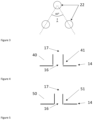
- Figure 3 shows an embodiment of a section of a tubesheet in a heat exchanger according to the present disclosure.
- the tubesheet comprises openings 22 for accommodating vertical tubes.
- the openings 22 follow a 60° staggered pattern, wherein the center of the three openings create an equilateral triangle, and point A is the center of the equilateral triangle.
- FIG 4 is a schematic drawing of a part of the distribution section of another embodiment of a vertical top-to-bottom shell-and-tube heat exchanger 40 according to the present disclosure.
- the heat exchanging section and collection section of device 40 are identical to device 1 and are not reproduced in Figure 4 to simplify the drawing.
- the distribution tray 14 comprises a plurality of hollow tubes 17 that are fastened on top 41 of the distribution tray 14. Hence, the diameter of the second set of through holes 16 is substantially equal to the diameter of the hollow tubes.
- FIG. 5 is a schematic drawing of a part of the distribution section of another embodiment of a vertical top-to-bottom shell-and-tube heat exchanger 50 according to the present disclosure.
- the heat exchanging section and collection section of device 50 are identical to device 1 and are not reproduced in Figure 5 to simplify the drawing.
- the distribution tray 14 comprises a plurality of hollow tubes 17 that are fastened inside 51 the through-holes of the second set of through-holes 16. Hence, the diameter of the second set of through holes 16 is larger than the diameter of the hollow tubes.
Landscapes
- Engineering & Computer Science (AREA)
- Physics & Mathematics (AREA)
- Thermal Sciences (AREA)
- Mechanical Engineering (AREA)
- General Engineering & Computer Science (AREA)
- Physical Or Chemical Processes And Apparatus (AREA)
- Heat-Exchange Devices With Radiators And Conduit Assemblies (AREA)
Abstract
The present disclosure provides a vertical top-to-bottom shell-and-tube heat exchanger and a method for condensing a gas stream comprising water, ammonia, and carbon dioxide.
Description
- The present disclosure is related to shell-and-tube heat exchangers.
- In chemical plants, a heat exchanger is a device that allows to heat up or cool down a fluid, i.e., a liquid or a gas, without direct contact between the fluid and the cooling or heating medium.
- There are different designs of such devices, and one of them is the falling film shell-and-tube heat exchanger, hereafter named falling film heat exchanger.
- A shell-and-tube heat exchanger is a device comprising three sections: a distributing section, wherein the fluid to be cooled or heated is introduced into the device and separated in sub-streams, a heat exchanging section, which comprises a body and a plurality of vertical tubes, wherein the plurality of vertical tubes directs the fluid to be cooled or heated from the distributing section to a collecting section wherein the cooled or heated fluid is recovered. The distributing section and the heat exchanging section are separated by a top tubesheet, which comprises holes to accommodate the vertical tubes. The heat exchanging section comprises two spaces: the shell space is the continuous space between the body and the plurality of vertical tubes, wherein the heating or cooling medium is circulated, and the tube space, which is the discontinuous space formed by the collection of the inside of each tube. Typically, the tubes are evenly distributed across the cross section of the shell in a shell-and-tube heat exchanger.
- Shell-and-tube heat exchangers are used in a wide range of industries, such as fertilizers. In some cases, the fluid to be cooled or heated, which may be a one-phase fluid (liquid or gas) or a 2-phase fluid (mixture of liquid and gas). The fluid may comprise components in a liquid phase such as ammonia, carbon dioxide, water and urea, and in a gas phase, such as ammonia, carbon dioxide and water. The fluid to be cooled or heated may contain corrosive compounds that may react with the heat exchanger. In order to protect the device, a passivation agent, such as air containing oxygen or hydrogen peroxide, may be injected in the exchanger or in the sections upstream of the device to protect the equipment: oxygen is always moving downstream and so remains in the liquid solution to be treated. It is important that the liquid solution containing passivation agent is evenly distributed to the vertical tubes of the heat exchanger in order to efficiently protect the device: a proper distribution of the liquid solution ensures an even distribution of the passivation agent on the exposed surfaces, including the top tubesheet. It has been seen that it may be difficult to obtain an even distribution of the liquid comprising the passivation agent to the plurality of vertical tubes and the top tubesheet of the heat exchanger: in such a case, vapors may condense on the un passivated surface causing corrosion.
- A new shell-and-tube heat exchanger was designed to improve the distribution of a liquid comprising a passivation agent. The heat exchanger comprises a distribution plate located above the top tubesheet of the heat exchanger, wherein the distribution plate is configured to distribute evenly the liquid across the tubesheet, ensuring that each tube of the exchanger receives some of the liquid comprising the passivation agent and the area of the top tubesheet between the holes for accommodating the vertical tubes is properly and evenly wetted.
- In a first aspect, the present disclosure provides a vertical top-to-bottom shell-and-tube heat exchanger for condensing a gas stream, the heat exchanger comprising a body, a distribution section, a heat exchanging section comprising a set of vertical tubes, an inlet for a cooling medium, an outlet for a cooling medium, and a collection section comprising a cooled fluid outlet, wherein:
- the distribution section and the heat exchanging section are separated by a top tubesheet comprising a plurality of openings configured to accommodate the vertical tubes;
- the distribution section comprises a gas inlet for a gas stream to be condensed, a liquid inlet for a liquid comprising a passivation agent, and a distribution tray located below the liquid inlet, wherein the distribution tray (14) is adapted to distribute both the gas stream and the liquid comprising passivation agent, wherein the distribution tray (14) comprises two sets of through-holes perforating the distribution tray, the first set of through-holes being configured to distribute the liquid comprising a passivation agent across the top of the top tubesheet, and the second set of through-holes being configured to allow the gas stream to reach the vertical tubes;
- the axis of each through-hole of the second set of through-holes is located directly above the axis of a vertical tube of the distribution section;
- the distribution tray comprises a plurality of hollow tubes fastened to the distribution tray, wherein the hollow tubes are configured to prevent liquid from reaching the through-holes of the second set of through-holes.
- In a second aspect, the present disclosure provides a method for condensing a gas stream comprising water, ammonium, and carbon dioxide, in a heat exchanger according to the present disclosure:
- a) directing a liquid comprising a passivation agent to the liquid inlet of the heat exchanger, in particular wherein the passivation agent is oxygen or oxygen peroxide;
- b) directing a stream of cooling liquid, such as water or steam condensate, to the inlet for a cooling medium of the heat exchanger;
- c) directing a gas stream comprising water, ammonium, and carbon dioxide, to the gas inlet of the heat exchanger;
- d) collecting a fluid comprising a liquid condensate from the first outlet of the heat exchanger.
- The following description of the figure of a specific embodiment of a system according to the present disclosure is only given by way of example and is not intended to limit the present explanation, its application or use. In the figures, identical reference numerals refer to the same or similar parts and features.
-
Figure 1 is a drawing of an embodiment of a vertical top-to-bottom shell-and-tube heat exchanger according to the present disclosure. -
Figure 2 is a drawing of a section of another embodiment of a vertical top-to-bottom shell-and-tube heat exchanger. -
Figure 3 is a drawing of an embodiment of the staggered pattern position of the vertical tubes in a vertical top-to-bottom shell-and-tube heat exchanger. -
Figures 4 and 5 are drawings of an embodiment of a part of the distribution section of a vertical top-to-bottom shell-and-tube heat exchanger. - Unless otherwise defined, all terms used in disclosing the invention, including technical and scientific terms, have the meaning as commonly understood by one of ordinary skill in the art to which this invention belongs. By means of further guidance, term definitions are included to better appreciate the teaching of the present invention.
- In the following passages, different aspects or embodiments of the invention are defined in more detail. Each aspect or embodiment so defined may be combined with any other aspect(s) or embodiment(s) unless clearly indicated to the contrary. In particular, any feature indicated as being preferred or advantageous may be combined with any other feature or features indicated as being preferred or advantageous.
- All references cited in this description are hereby deemed to be incorporated in their entirety by way of reference.
- As used herein, the following terms have the following meanings:
"A", "an", and "the" as used herein refers to both singular and plural referents unless the context clearly dictates otherwise. By way of example, "a compartment" refers to one or more than one compartment. - "About" as used herein referring to a measurable value such as a parameter, an amount, a temporal duration, and the like, is meant to encompass variations of +/-20 % or less, in particular +/-10 % or less, more in particular +/-5 % or less, even more in particular +/-1 % or less, and still more in particular +/-0.1 % or less of and from the specified value, in so far such variations are appropriate to perform in the disclosed invention. However, it is to be understood that the value to which the modifier "about" refers is itself also specifically disclosed.
- "Comprise", "comprising", and "comprises" and "comprised of" as used herein are synonymous with "include", "including", "includes" or "contain", "containing", "contains" and are inclusive or open-ended terms that specifies the presence of what follows and do not exclude or preclude the presence of additional, non-recited components, features, element, members, steps, known in the art or disclosed therein.
- The recitation of numerical ranges by endpoints includes all numbers and fractions subsumed within that range, as well as the recited endpoints.
- The expression "weight percent", "°/wt" or "weight%", here and throughout the description unless otherwise defined, refers to the relative weight of the respective component based on the overall weight of the formulation.
- In a first aspect, the present disclosure provides a shell-and-tube heat exchanger, preferably a vertical top-to-bottom shell-and-tube heat exchanger, for condensing a gas stream, the heat exchanger comprising a body, a distribution section, a heat exchanging section comprising a set of vertical tubes, an inlet for a cooling medium, an outlet for a cooling medium, and a collection section comprising a cooled fluid outlet for a fluid comprising a liquid and optionally gases, wherein:
- the distribution section and the heat exchanging section are separated by a top tubesheet comprising a plurality of openings configured to accommodate the vertical tubes;
- the distribution section comprises a gas inlet for a gas stream to be condensed, a liquid inlet for a liquid comprising a passivation agent, and a distribution tray located below the liquid inlet, wherein the distribution tray (14) is adapted to distribute both the gas stream and the liquid comprising passivation agent, wherein the distribution tray comprises two sets of through-holes perforating the distribution tray, the first set of through-holes being configured to distribute the liquid comprising a passivation agent across the top of the top tubesheet, and the second set of through-holes being configured to allow the gas stream to reach the vertical tubes;
- the axis of each through-hole of the second set of through-holes is located directly above the axis of a vertical tube of the distribution section;
- the distribution tray comprises a plurality of hollow tubes fastened to the distribution tray, wherein the hollow tubes are configured to prevent liquid from reaching the through-holes of the second set of through-holes.
- The heat exchanger comprises a distribution section, a heat exchanging section, and a collection section, all three sections being enclosed in a body. The distribution section is located at the top of the device, the heat exchanging section is located between the distribution section and the collection section, and the collection section is located at the bottom of the device.
- The heat exchanging section is separated from the distribution section by a top tubesheet comprising a plurality of openings configured to accommodate a set of vertical tubes. The vertical tubes are configured to direct the liquid containing the passivation agent, the gas stream, and the condensate of the gas stream, from the distribution section to the collection section. The heat exchanging section comprises two spaces: a continuous space outside the vertical tubes also called shell space, and a discontinuous collection of internal spaces of the vertical tubes also called tube space. In the present heat exchanger, the shell space is configured to receive a cooling fluid, in particular cooling water or steam condensate. Cooling water used in industrial plants, such as urea-producing plants, comprises mostly water. Cooling water may also comprise additives, such as inorganic salts, and small organic molecules. In the present heat exchanger, the tube space is configured to receive the gas stream to be condensed and the liquid comprising a passivation agent. The liquid comprising the passivation agent accumulates on the top tubesheet, and enters the tubes, forming a falling film on the inside walls of the vertical tubes. The gas stream comprising water, ammonia, and carbon dioxide condenses as it travels in the tubes and increases the thickness of the falling film. The condensate obtained from the gas stream flows down to the collection section.
- In some embodiments, the liquid comprising a passivation agent comprises ammonia, and/or carbon dioxide, and/or ammonium carbamate, and/or ammonium carbonate.
- The heat exchanging section comprises an inlet for a cooling medium, and a second outlet for a cooling medium. The inlet and second outlet for a cooling medium are located on the wall of the section.
- In some embodiments, the inlet for a cooling medium is located above the second outlet for a cooling medium. In some embodiments, the inlet for a cooling medium is located below the second outlet for a cooling medium.
- The collection section comprises a first outlet for removing the fluid produced by the condenser. The removed fluid may comprise only liquid components, such as the condensate from the gas stream and the liquid comprising a passivation agent, but it may also comprise gases, i.e., uncondensed vapors.
- The distribution section comprises a gas inlet for a gas stream to be condensed, a liquid inlet for the liquid containing the passivation agent, and a distribution tray located below the liquid inlet, wherein the distribution tray comprises two sets of through-holes, the first set of through-holes being configured to distribute the liquid comprising the passivation agent across the top of the top tubesheet, and the second set of through-holes being configured to allow the gas stream to reach the vertical tubes. The role of the distribution tray is two-fold: ensure that the gas stream to be condensed can flow from the gas inlet to the vertical tubes and distribute evenly the liquid entering the heat exchanger from the liquid inlet across the top tubesheet.
- The role of the liquid containing passivation agent is to bring the passivation agent, for example oxygen, in contact or near the internal surface of the wall of the vertical tubes of the heat exchanger and on the surface of the top tubesheet. The passivation agent is carefully selected such that it can react with the material of the vertical tubes and the top tubesheet to create a layer of material that is more resistant to corrosion than the material of the vertical tubes and of the top tubesheet.
- The top tubesheet is a perforated plate that comprises openings to accommodate the vertical tubes of the condenser.
- In some embodiments, the axis of at least one through-hole of the first set of through-holes of the distribution tray may be equidistant to the nearest openings of the top tubesheet. In order to obtain a good distribution of the liquid comprising a passivation agent, it may be an advantage that the axis of at least one through-hole among the first set of through-holes of the distribution plate is equidistant to the nearest openings of the top tubesheet. This means that the liquid comprising a passivation agent can fall onto the top tubesheet at equidistance of several openings of the top tubesheet and it can evenly spread in all directions, ensuring a good coverage of the top tubesheet, and a more even film formation inside the vertical tubes.
- In some embodiments, the axis of at least one through-hole of the first set of through-holes may be located directly above the axis of the center of the triangular pitch of the openings of the top tubesheet. For a shell-and-tube heat exchanger, such as a condenser, the vertical tubes are often positioned in a staggered pattern, in particular staggered with 60° as shown on
Figure 3 . In such configuration, the axis of at least one though-hole of the first set of through-hole of the distribution tray may go through the center of the triangle created by the center of three openings. - In some embodiments, the axis of the through-holes of the first set of through-holes may be located directly above the axis of the center of the triangular pitch of the openings of the top tubesheet.
- In some embodiments, the gas stream and/or the condensate from the gas stream comprises corrosive compounds that may react with the vertical tubes and slowly corrode the tubes. This can eventually lead to holes in the vertical tubes, which breaks the impermeable barrier between the shell space and the tube space. Such damage requires blocking the top end and the bottom end of the tubes, or to replace the tube. For example, a urea-producing plant comprises one or more condensers that are configured to condense gas streams comprising water, carbon dioxide and ammonia. The condensate of such gas streams comprises a compound selected from the group of ammonium carbamate, ammonium carbonate, ammonium bicarbonate, and mixtures thereof. Such compounds are corrosive to stainless steel, and the condensers need to be protected from the corrosive action of these compounds.
- Gas streams comprising oxygen may be injected in the condensers to provide a passivation effect. However, since the vertical tubes are covered by a liquid film in operation, it is required that the gaseous oxygen dissolves in the liquid film to passivate the tubes. Thus, it is often preferred to use a liquid comprising a passivation agent, such as oxygen or oxygen peroxide. The passivation agent is present in the liquid film falling inside the tube and can react with the tubes to create a passivated layer.
- A conventional way to introduce the liquid containing the passivation agent to a shell-and-tube heat exchanger is to spray the liquid with a spraying device above the top tubesheet. However, it was found that when the pressure or velocity of the stream of liquid was varying in operation, the spraying pattern, for example a full cone shape, did not cover the entire top tubesheet. As a result, some of the tubes and part of the top tubesheet area did not receive the desired amount of the liquid comprising the passivation agent, and corrosion was increased leading to a reduced lifetime of the vertical tubes and the top tubesheet, in particular the welding points between the tubesheet and the vertical tubes. So, a new system for distributing the liquid comprising the passivation agent to the top tubesheet was designed.
- It was found that a distribution tray comprising two sets of through-holes ensured an even distribution of liquid containing the passivation agent to the top tubesheet. The distribution tray is located below the liquid inlet and above the top tubesheet. The distribution tray comprises two sets of through-holes, the first set of through-holes is configured to distribute the liquid comprising the passivation agent across the top of the top tubesheet, and the second set of through-holes is configured to allow the gas stream to reach the vertical tubes.
- Each through-hole of the first set of through-holes is located above a solid section of the top tubesheet, meaning that the liquid comprising the passivation agent falling from the first set of through-holes falls onto the top tubesheet and is distributed across the top tubesheet. The top end of each vertical tube connecting the distribution section to the collection section is above the top tubesheet, such that a certain volume of liquid comprising the passivation agent is always present on the top tubesheet in operations.
- The axis of each through-hole of the second set of through-holes is located directly above the axis of a vertical tube of the distribution section, such that the gas stream to be condensed can reach the vertical tubes in an almost laminar flow.
- The heat exchanger comprises a plurality of hollow tubes fastened to the distribution tray, wherein the hollow tubes are configured to prevent liquid from reaching the through-holes of the second set of through-holes. The hollow tubes prevent the liquid comprising the passivation agent from falling directly into the vertical tubes, which may disturb the gas distribution into the tubes, and allow the to be condensed gas stream to pass through the distribution plate.
- In some embodiments, the hollow tubes are fastened on top of the distribution tray.
- In some embodiments, the hollow tubes are fastened inside the through-holes of the second set of through-holes.
- At least two ways to attach the hollow tubes to the distribution tray are envisioned. Firstly, the hollow tubes can be fastened on top of the distribution tray. In this case, it may be preferred that the internal dimeter of the hollow tubes is equal to the diameter of the through-holes of the second set of through-holes. Secondly, the hollow tubes can be fastened inside the through-holes of the second set of through-holes. In this case, it may be preferred that the external diameter of the hollow tubes is equal or from 0.1 to 2.0 mm smaller than the diameter of the through-holes of the second set of through-holes, such that the hollow tubes fit inside the through-holes.
- In some embodiments, the bottom end of the hollow tubes is flush with the bottom face of the distribution tray.
- In some embodiments, the distribution section comprises a distribution tube, in particular an L-shaped distribution tube, wherein one end of the distribution tube is connected to the liquid inlet and the other end, the outlet of the distribution tube, is located above a non-perforated part of the distribution tray. A distribution tube connected to the liquid inlet on one end, with its other end located above a non-perforated part of the distribution tray, may provide a more controlled distribution of the liquid comprising the passivation agent to the distribution tray, providing a more stable liquid level and ensuring an even liquid flow through the first set of through-holes.
- In some embodiments, the outlet of the distribution tube is located above a non-perforated part of the distribution tray is from 10.0 to 100.0 mm above the distribution tray.
- In some embodiments, the outlet of the distribution tube is located above a non-perforated part of the distribution tray and is surrounded by a wall extending from the distribution tray, in particular wherein the wall is cylindrical and/or perforated. Depending on the pressure and velocity of the stream of the liquid comprising the passivation agent, and the height difference between the inlet and the distribution tray, the impact of the liquid containing the passivation agent onto the distribution tray may create a very turbulent zone, including droplets that may enter the hollow tubes and leading to an unstable stable liquid level above the distribution tray. It was found that a wall extending from the distribution tray and surrounding the outlet of the distribution tube reduced the turbulence zone created by the impact of the liquid onto the distribution plate. The turbulence zone is limited to the internal volume of the wall. The liquid comprising the passivation agent reaches the entire distribution tray by flowing over the wall, or through the perforations, if present, in a much more controlled way and with less velocity than at the outlet of the distribution tube.
- In some embodiments, the wall surrounding the outlet of the distribution tube comprises perforations, in particular perforations having a diameter ranging from 2.0 to 8.0 mm, or from 2.0 to 5.0 mm.
- In some embodiments, the wall surrounding the outlet of the distribution tube has a height of from 100.0 to 300.0 mm. In some embodiments, the wall surrounding the outlet of the distribution tube has a height of from 100.0 to 200.0 mm.
- In some embodiments, the wall is cylindrical and the distance between the center of the wall and the center of the distribution tray is from 0.0 mm to 25% of the diameter of the distribution tray. A cylindrical wall ensures that the liquid comprising the passivation agent is distributed evenly in all directions from the wall. A wall located around the middle of the distribution tray also provides a more even distribution of the liquid across the distribution plate. It may not be possible for the wall to be at the exact center of the distribution tray because of the location of a through hole or a hollow tube, but it was observed that the wall could be at a distance from the center, such as less than 20% of the diameter of the distribution tray, and still provide a very good distribution of the liquid comprising a passivation agent.
- In some embodiments, the height of the hollow tubes is from 200.0 to 500.0 mm. In some embodiments, the height of the hollow tubes is from 200.0 to 400.0 mm. In some embodiments, the height of the hollow tubes is from 300.0 to 400.0 mm. The main role of the hollow tubes is to prevent the liquid containing the passivation agent from falling through the second set of through holes. Their height determines how much liquid can be accumulated on the distribution tray.
- In some embodiments, the diameter of the through-holes of the first set of through-holes is smaller than the diameter of the through-holes of the second set of through-holes. The volume of liquid containing the passivation agent used in such heat exchangers is often much smaller than the volume of gas stream to be condensed, by unit of time, so the amount of gas that needs to go through the second set of through/holes is greater than the amount of liquid that needs to go through the first set of through holes. So, a larger diameter for the second set of through/holes allows to reduce the pressure drop caused by the distribution tray.
- In some embodiments, the diameter of the through-holes of the first set of through-holes is ranging from 2.0 to 8.0 mm, or from 2.0 to 6.0 mm.
- In some embodiments, the diameter of the through-holes of the second set of through-holes is ranging from 10.0 to 25.0 mm, or from 15.0 to 25.0 mm.
- In another aspect, the present disclosure provides a method for condensing a gas stream comprising water, ammonium, and carbon dioxide, in a heat exchanger according to the present disclosure:
- a) directing a liquid comprising a passivation agent to the liquid inlet of the heat exchanger, in particular wherein the passivation agent is oxygen or oxygen peroxide;
- b) directing a stream of cooling liquid, such as water or steam condensate, to the inlet for a cooling medium of the heat exchanger;
- c) directing a gas stream comprising water, ammonium, and carbon dioxide, to the gas inlet of the heat exchanger;
- d) collecting a fluid comprising liquid condensate from the cooled fluid outlet of the heat exchanger.
- The heat exchanger described above can be used in a method for condensing a gas stream comprising water, ammonium, and carbon dioxide. For example, urea-producing plants have several devices that produces a gas stream comprising water, ammonia, and carbon dioxide. Ammonia and carbon dioxide are the raw materials used to produce urea, and it is desirable to recycle these components back to the synthesis section or the medium-pressure section or the low-pressure section as an aqueous solution instead of a gas stream.
- A carbamate condenser is a heat exchanger configured to condense a gas stream comprising water, ammonia, and carbon dioxide, into an aqueous solution comprising ammonium ions, such as ammonium carbamate, ammonium carbonate, and ammonium bicarbonate. The heat exchanger described above can be used as a carbamate condenser in a urea-producing plant.
- A liquid comprising a passivation agent is directed to the liquid inlet of the heat exchanger. In some embodiments, the liquid is an aqueous solution comprising oxygen or oxygen peroxide. The liquid comprising the passivation agent may comprise other components. In some embodiments, the liquid comprising the passivation agent comprises ammonia, and/or carbon dioxide, and/or urea.
- A cooling liquid, such as water or steam condensate, is directed to the inlet for a cooling medium of the heat exchanger. If the cooling liquid is essentially water, it may comprise some inorganic salts or organic molecules. For example, calcium salts are often added to cooling water in urea-producing plants. In some embodiments, the cooling liquid has a pH above 7.0. In some embodiments, the cooling liquid comprises basic additives such that its pH is above 7.0.
- A gas stream comprising water, ammonium, and carbon dioxide, is directed to the gas inlet of the heat exchanger. The gas stream may come from any device of a urea-producing plant, such as a carbamate decomposer or a desorption column. When the gas stream reaches the vertical tubes of the heat exchanger, the water comprised in the gas stream condenses into liquid water. The ammonia and carbon dioxide comprised in the gas stream dissolve in the water, and react together to form ammonium carbamate, ammonium carbonate, or ammonium bicarbonate depending on the exact conditions inside the vertical tubes, such as pressure temperature, and composition of the gas stream. The reaction of ammonia and carbon dioxide drives the solubilization of the gases into the liquid phase.
- In some embodiments, the gas stream comprising water, ammonium, and carbon dioxide has a pressure ranging from 0.1 M to 4.0 MPa. In some embodiments, the gas stream comprising water, ammonium, and carbon dioxide has a pressure ranging from 3.0 M to 4.0 MPa.
- A liquid condensate is recovered from the cooled fluid outlet of the heat exchanger. In some embodiments, the liquid condensate comprises one or more components selected from the group consisting of ammonium carbamate, ammonium carbonate, and ammonium bicarbonate. In some embodiments there is no total condensation of the vapors and a mixed stream of liquid and vapors is recovered from the cooled fluid outlet.
- In some embodiments, the liquid comprising the passivation agent, and directed to the liquid inlet of the distribution section, comprises a portion of the condensate collected from the cooled fluid outlet. It was found that it was possible to use the liquid condensate obtained in the collections section of the heat exchanger as part of the liquid comprising the passivation agent in the same device. This has the advantage that it allows to reduce the consumption of water of the plant and does not modify the chemical composition of the condensate.
-
Figure 1 is a schematic drawing of an embodiment of a vertical top-to-bottom shell-and-tube heat exchanger 1 according to the present disclosure. Thedevice 1 comprises abody 5, adistribution section 2, aheat exchanging section 3, and acollection section 4. Thecollection section 4 comprising a cooledfluid outlet 13 for removing condensate from thedevice 1. Theheat exchanging section 3 comprisesvertical tubes 10 fluidly connecting thedistribution section 2 and thecollection section 4. Theheat exchanging section 3 comprises an inlet for acooling medium 9, and an outlet for a coolingmedium 12. Thespace 11 between thebody 5 and the outside of thevertical tubes 11 is called the shell space. - The
distribution section 2 and theheat exchanging section 3 are separated by atop tubesheet 8. Thecollection section 4 and theheat exchanging section 3 are separated by abottom tubesheet 18. Thetubesheets vertical tubes 10. - The
distribution section 2 comprises agas inlet 7 for a gas stream to be condensed, aliquid inlet 6 for a liquid comprising a passivation agent, and adistribution tray 14 located below theliquid inlet 6 and above thetop tubesheet 8, wherein thedistribution tray 14 comprises two sets of through-holes holes 15 is configured to distribute the liquid containing the passivation agent across the top of thetop tubesheet 8, and the second set of through-holes 16 is configured to allow the gas stream to reach thevertical tubes 10. The axis of each through-hole of the second set of through-holes 16 is located directly above the axis of a vertical tube of thedistribution section 2. Thedistribution tray 14 comprises a plurality ofhollow tubes 17 fastened to thedistribution tray 14, wherein thehollow tubes 17 are configured to prevent liquid from reaching the through-holes of the second set of through-holes 16. -
Figure 2 is a schematic drawing of a section of another embodiment of a vertical top-to-bottom shell-and-tube heat exchanger 20 according to the present disclosure. The heat exchanging section and collection section ofdevice 20 are identical todevice 1 and are not reproduced inFigure 2 to simplify the drawing. Thedistribution section 2 comprises agas inlet 7, aliquid inlet 6, and adistribution tray 14 comprising two sets of through-holes holes 15 is configured to distribute the liquid containing the passivation agent across the top of thetop tubesheet 8, and the second set of through-holes 16 is configured to allow the gas stream to reach thevertical tubes 10. Thedistribution tray 14 comprises a plurality ofhollow tubes 17 fastened to thedistribution tray 14. Thedistribution section 2 comprises a L-shapeddistribution tube 21 connected on one end to theliquid inlet 6. The outlet of thedistribution tube 21 is located above a solid section of thedistribution tray 14 and is surrounded by acircular wall 19 that is configured to minimize the turbulences caused by the impact of the liquid comprising a passivation agent on thedistribution tray 14. The distance between the center of thewall 19 and the center of thedistribution tray 14 is about between 0 and 25 % of the diameter of thedistribution tray 14. -
Figure 3 shows an embodiment of a section of a tubesheet in a heat exchanger according to the present disclosure. The tubesheet comprisesopenings 22 for accommodating vertical tubes. Theopenings 22 follow a 60° staggered pattern, wherein the center of the three openings create an equilateral triangle, and point A is the center of the equilateral triangle. -
Figure 4 is a schematic drawing of a part of the distribution section of another embodiment of a vertical top-to-bottom shell-and-tube heat exchanger 40 according to the present disclosure. The heat exchanging section and collection section ofdevice 40 are identical todevice 1 and are not reproduced inFigure 4 to simplify the drawing. Thedistribution tray 14 comprises a plurality ofhollow tubes 17 that are fastened ontop 41 of thedistribution tray 14. Hence, the diameter of the second set of throughholes 16 is substantially equal to the diameter of the hollow tubes. -
Figure 5 is a schematic drawing of a part of the distribution section of another embodiment of a vertical top-to-bottom shell-and-tube heat exchanger 50 according to the present disclosure. The heat exchanging section and collection section ofdevice 50 are identical todevice 1 and are not reproduced inFigure 5 to simplify the drawing. Thedistribution tray 14 comprises a plurality ofhollow tubes 17 that are fastened inside 51 the through-holes of the second set of through-holes 16. Hence, the diameter of the second set of throughholes 16 is larger than the diameter of the hollow tubes.
Claims (13)
- A vertical top-to-bottom shell-and-tube heat exchanger (1) for condensing a gas stream, the heat exchanger comprising a body (5), a distribution section (2), a heat exchanging section (3) comprising a set of vertical tubes (10), an inlet for a cooling medium (9), an outlet for a cooling medium (12), and a collection section (4) comprising a cooled fluid outlet (13), wherein:- the distribution section (2) and the heat exchanging section (3) are separated by a top tubesheet (8) comprising a plurality of openings configured to accommodate the vertical tubes (10);- the distribution section (2) comprises a gas inlet (7) for a gas stream to be condensed, a liquid inlet (6) for a liquid comprising a passivation agent, and a distribution tray (14) located below the liquid inlet (6), wherein the distribution tray (14) is adapted to distribute both the gas stream and the liquid comprising passivation agent, the distribution tray (14) comprising two sets of through-holes (15, 16) perforating the distribution tray (14), the first set of through-holes (15) being configured to distribute the liquid comprising a passivation agent across the top of the top tubesheet (8), and the second set of through-holes (16) being configured to allow the gas stream to reach the vertical tubes (10);- the axis of each through-hole of the second set of through-holes (16) is located directly above the axis of a vertical tube of the distribution section (2);- the distribution tray (14) comprises a plurality of hollow tubes (17) fastened to the distribution tray (14), wherein the hollow tubes (17) are configured to prevent liquid from reaching the through-holes of the second set of through-holes (16).
- The heat exchanger according to claim 1, wherein the axis of at least one through-hole of the first set of through-holes (15) is located directly above the axis of the center of the triangular pitch of the tubes (10).
- The heat exchanger according to claim 1 or 2, further comprising a distribution tube (21), in particular an L-shaped distribution tube, wherein one end of the distribution tube (21) is connected to the liquid inlet (6) and the other end is located above a non-perforated part of the distribution tray (14).
- The heat exchanger according to claim 3, wherein the end of the distribution tube (21) is located above a non-perforated part of the distribution tray (14) is from 10.0 to 100.0 mm above the distribution tray (14).
- The heat exchanger according to claim 3 or 4, wherein the end of the distribution tube (21) is located above a non-perforated part of the distribution tray (14) is surrounded by a perforated wall (19) extending from the distribution tray (14), in particular wherein the wall (19) is cylindrical.
- The heat exchanger according to claim 5, wherein the wall (19) has a height of from 100.0 to 300.0 mm.
- The heat exchanger according to claim 5 or 6, wherein the wall (19) is cylindrical and the distance between the center of the wall (19) and the center of the distribution tray (14) is from 0.0 mm to 25% of the diameter of the distribution tray (14).
- The heat exchanger according to any one of claims 1 to 7, wherein the height of the hollow tubes (17) is from 200.0 to 500.0 mm.
- The heat exchanger according to any one of claims 1 to 8, wherein the diameter of the through-holes of the first set of through-holes (15) is smaller than the diameter of the through-holes of the second set of through-holes (16).
- The heat exchanger according to any one of claims 1 to 9, wherein the hollow tubes (17) are fastened on top (41) of the distribution tray (14).
- The heat exchanger according to any one of claims 1 to 9, wherein the hollow tubes (17) are fastened inside (51) the through-holes of the second set of through-holes (16).
- A method for condensing a gas stream comprising water, ammonium, and carbon dioxide, in a heat exchanger according to any one of claims 1 to 11:a) directing a liquid comprising a passivation agent to the liquid inlet (6) of the heat exchanger, in particular wherein the passivation agent is oxygen or oxygen peroxide;b) directing a stream of cooling liquid, such as water, to the inlet for a cooling medium (9) of the heat exchanger;c) directing a gas stream comprising water, ammonium, and carbon dioxide, to the gas inlet (7) of the heat exchanger;d) collecting a fluid comprising liquid condensate from the cooled fluid outlet (13) of the heat exchanger.
- The use of a vertical top-to-bottom shell-and-tube heat exchanger according to any one of claims 1 to 11 to condense a gas stream, in particular wherein the gas stream comprises water, ammonia and carbon dioxide.
Priority Applications (3)
| Application Number | Priority Date | Filing Date | Title |
|---|---|---|---|
| EP23218629.6A EP4575380A1 (en) | 2023-12-20 | 2023-12-20 | Shell-and-tube heat exchanger |
| CN202480065803.7A CN122029397A (en) | 2023-12-20 | 2024-12-20 | Shell-and-tube heat exchanger |
| PCT/EP2024/087809 WO2025133055A1 (en) | 2023-12-20 | 2024-12-20 | Shell-and-tube heat exchanger |
Applications Claiming Priority (1)
| Application Number | Priority Date | Filing Date | Title |
|---|---|---|---|
| EP23218629.6A EP4575380A1 (en) | 2023-12-20 | 2023-12-20 | Shell-and-tube heat exchanger |
Publications (1)
| Publication Number | Publication Date |
|---|---|
| EP4575380A1 true EP4575380A1 (en) | 2025-06-25 |
Family
ID=89224231
Family Applications (1)
| Application Number | Title | Priority Date | Filing Date |
|---|---|---|---|
| EP23218629.6A Pending EP4575380A1 (en) | 2023-12-20 | 2023-12-20 | Shell-and-tube heat exchanger |
Country Status (3)
| Country | Link |
|---|---|
| EP (1) | EP4575380A1 (en) |
| CN (1) | CN122029397A (en) |
| WO (1) | WO2025133055A1 (en) |
Citations (4)
| Publication number | Priority date | Publication date | Assignee | Title |
|---|---|---|---|---|
| GB1508836A (en) * | 1974-07-08 | 1978-04-26 | Mitsui Toatsu Chemicals | Chemical process and apparatus for corrosive materials |
| US4173615A (en) * | 1974-07-08 | 1979-11-06 | Mitsui Toatsu Chemicals, Incorporated | Chemical apparatus for corrosive materials |
| EP1503837B1 (en) * | 2002-05-13 | 2014-07-09 | Saipem S.p.A. | Tube bundle apparatus for processing corrosive fluids, method of preparing said apparatus and use thereof in a urea synthesis plant |
| AU2020311257A1 (en) * | 2019-07-05 | 2022-02-17 | Stamicarbon B.V. | Ferritic steel parts in urea plants |
-
2023
- 2023-12-20 EP EP23218629.6A patent/EP4575380A1/en active Pending
-
2024
- 2024-12-20 WO PCT/EP2024/087809 patent/WO2025133055A1/en active Pending
- 2024-12-20 CN CN202480065803.7A patent/CN122029397A/en active Pending
Patent Citations (4)
| Publication number | Priority date | Publication date | Assignee | Title |
|---|---|---|---|---|
| GB1508836A (en) * | 1974-07-08 | 1978-04-26 | Mitsui Toatsu Chemicals | Chemical process and apparatus for corrosive materials |
| US4173615A (en) * | 1974-07-08 | 1979-11-06 | Mitsui Toatsu Chemicals, Incorporated | Chemical apparatus for corrosive materials |
| EP1503837B1 (en) * | 2002-05-13 | 2014-07-09 | Saipem S.p.A. | Tube bundle apparatus for processing corrosive fluids, method of preparing said apparatus and use thereof in a urea synthesis plant |
| AU2020311257A1 (en) * | 2019-07-05 | 2022-02-17 | Stamicarbon B.V. | Ferritic steel parts in urea plants |
Also Published As
| Publication number | Publication date |
|---|---|
| WO2025133055A1 (en) | 2025-06-26 |
| CN122029397A (en) | 2026-05-12 |
Similar Documents
| Publication | Publication Date | Title |
|---|---|---|
| US6089312A (en) | Vertical falling film shell and tube heat exchanger | |
| CN1320938C (en) | Hydraulically sealed crossflow mass transfer tray | |
| EP2073912B1 (en) | Method and apparatus for improved gas/fluid contact | |
| EA001995B1 (en) | A scrubber for the treatment of flue gases | |
| US11571678B2 (en) | High pressure strippers for use in urea plants | |
| US11992789B2 (en) | High pressure strippers for use in urea plants | |
| US12595977B2 (en) | Baffles for heat exchangers | |
| CA2696275A1 (en) | Systems and methods for removing gaseous pollutants from a gas stream | |
| NL8102439A (en) | DEVICE FOR DISTRIBUTING A LIQUID AS A THIN LAYER IN VERTICAL HEAT EXCHANGER. | |
| CN113710341B (en) | High-pressure strippers used in urea plants | |
| AU2020278868B2 (en) | Treatment of offgas from urea finishing | |
| US20030059352A1 (en) | Process and apparatus for scrubbing sulfur dioxide from flue gas and conversion to fertilizer | |
| WO2025133055A1 (en) | Shell-and-tube heat exchanger | |
| EP2173464A1 (en) | Fluid distribution system | |
| WO2022094048A2 (en) | Compact venturi scrubber and method to treat gas streams utilizing the compact venturi scrubber | |
| JP4905926B2 (en) | Two-chamber wet flue gas desulfurization system | |
| EP4508026B1 (en) | A falling film heat exchanger | |
| JP7243057B2 (en) | Gas-liquid contactor | |
| JP7618966B2 (en) | Gas-liquid contactor | |
| US12030011B2 (en) | Air scrubber having an interior air exhaust | |
| CA3172837A1 (en) | Distribution chamber for liquid stream | |
| RU2803814C2 (en) | High pressure stripper columns for use in urea plants | |
| WO2025133297A1 (en) | Degassing system in particular for urea plant | |
| RU2336931C1 (en) | Heat-and-mass exchanger for wet clearing | |
| JP2008260003A (en) | Gas-liquid contact device |
Legal Events
| Date | Code | Title | Description |
|---|---|---|---|
| PUAI | Public reference made under article 153(3) epc to a published international application that has entered the european phase |
Free format text: ORIGINAL CODE: 0009012 |
|
| STAA | Information on the status of an ep patent application or granted ep patent |
Free format text: STATUS: THE APPLICATION HAS BEEN PUBLISHED |
|
| AK | Designated contracting states |
Kind code of ref document: A1 Designated state(s): AL AT BE BG CH CY CZ DE DK EE ES FI FR GB GR HR HU IE IS IT LI LT LU LV MC ME MK MT NL NO PL PT RO RS SE SI SK SM TR |
|
| STAA | Information on the status of an ep patent application or granted ep patent |
Free format text: STATUS: THE APPLICATION IS DEEMED TO BE WITHDRAWN |