EP4575329A1 - Heat pump - Google Patents
Heat pump Download PDFInfo
- Publication number
- EP4575329A1 EP4575329A1 EP23219888.7A EP23219888A EP4575329A1 EP 4575329 A1 EP4575329 A1 EP 4575329A1 EP 23219888 A EP23219888 A EP 23219888A EP 4575329 A1 EP4575329 A1 EP 4575329A1
- Authority
- EP
- European Patent Office
- Prior art keywords
- space
- separation box
- indoor unit
- heat medium
- heat pump
- Prior art date
- Legal status (The legal status is an assumption and is not a legal conclusion. Google has not performed a legal analysis and makes no representation as to the accuracy of the status listed.)
- Pending
Links
Images






Classifications
-
- F—MECHANICAL ENGINEERING; LIGHTING; HEATING; WEAPONS; BLASTING
- F24—HEATING; RANGES; VENTILATING
- F24H—FLUID HEATERS, e.g. WATER OR AIR HEATERS, HAVING HEAT-GENERATING MEANS, e.g. HEAT PUMPS, IN GENERAL
- F24H4/00—Fluid heaters characterised by the use of heat pumps
- F24H4/02—Water heaters
- F24H4/04—Storage heaters
-
- F—MECHANICAL ENGINEERING; LIGHTING; HEATING; WEAPONS; BLASTING
- F24—HEATING; RANGES; VENTILATING
- F24D—DOMESTIC- OR SPACE-HEATING SYSTEMS, e.g. CENTRAL HEATING SYSTEMS; DOMESTIC HOT-WATER SUPPLY SYSTEMS; ELEMENTS OR COMPONENTS THEREFOR
- F24D19/00—Details
- F24D19/08—Arrangements for drainage, venting or aerating
- F24D19/082—Arrangements for drainage, venting or aerating for water heating systems
- F24D19/083—Venting arrangements
-
- F—MECHANICAL ENGINEERING; LIGHTING; HEATING; WEAPONS; BLASTING
- F24—HEATING; RANGES; VENTILATING
- F24F—AIR-CONDITIONING; AIR-HUMIDIFICATION; VENTILATION; USE OF AIR CURRENTS FOR SCREENING
- F24F11/00—Control or safety arrangements
- F24F11/30—Control or safety arrangements for purposes related to the operation of the system, e.g. for safety or monitoring
- F24F11/32—Responding to malfunctions or emergencies
- F24F11/36—Responding to malfunctions or emergencies to leakage of heat-exchange fluid
Definitions
- the present disclosure relates to heat pumps, particularly heat pumps used for heating and/or cooling purposes, particularly in commercial and private buildings. More particularly, the present disclosure relates to heat pumps of the so-called hydro split type comprising a heat exchanger (usage side heat exchanger) for transferring heat between a refrigerant and a heat medium such as water, wherein the refrigerant circuit, including the usage side heat exchanger, is entirely located outdoors.
- a heat exchanger usage side heat exchanger
- R290 propane is one of the refrigerants used in heat pumps of the above type because propane has a GBP of three and an ODP of zero.
- Heat pumps of the hydro split type comprise a primary circuit (refrigerant circuit) connecting a heat source heat exchanger, such as an air to refrigerant heat exchanger, an expansion valve, the usage side heat exchanger, such as a plate heat exchanger, and a compressor.
- the primary circuit of a hydro split type heat pump is usually located outdoors (outside of the building) and particularly in a housing of an outdoor unit.
- refrigerant may leak from the refrigerant circuit into the heat medium circuit.
- gaseous refrigerant may exit the heat medium circuit via the pressure relief valve and enter the indoor unit housing.
- the indoor unit housing very often also accommodates components such as electrical and/or electronic components which may be considered an ignition source.
- components such as electrical and/or electronic components which may be considered an ignition source.
- refrigerants used nowadays are often flammable or even highly flammable, such as R290, refrigerant entering the indoor unit housing is hazardous.
- a heat pump according to the present disclosure is defined in claim 1. Particular embodiments are defined in the dependent claims.
- the heat pump further comprises a heat medium circuit connecting the usage side heat exchanger, a pump and a load.
- the heat medium circuit contains a heat medium, which may be water.
- the pump particularly serves for circulating the heat medium within the heat medium circuit.
- the load may for example be at least one of a domestic hot water tank, loops of a floor heating and radiators.
- the heat medium circuit further comprises a pressure relief valve accommodated in an indoor unit housing.
- the pressure relief valve has an outlet for releasing gas and/or liquid from the heat medium circuit.
- the pressure relief valve may for example be part of a magnetic filter connected to the heat medium circuit (see later).
- the indoor unit housing has a machine chamber and the pressure relief valve is located in the machine chamber.
- the heat medium circuit may be accommodated in the indoor unit housing, particularly the machine chamber, such as the pump.
- the load is a domestic hot water tank
- the domestic hot water tank may be located in a tank chamber of the indoor unit housing below the machine chamber.
- the heat medium circuit may comprise heat medium pipes connecting the usage side heat exchanger located outdoors with the components of the heat medium circuit located indoors, such as in the indoor unit housing.
- the two parts may also be hinged to each other having a snap connection opposite to the hinge for fixing the parts to each other.
- the top part and the bottom part may be permanently welded together in order to enhance the sealing of the separation box.
- the separation box may be accommodated in an insulation, wherein the insulation may provide for a double function of thermally and/or electrically insulating as well as supporting the separation box within the machine chamber of the indoor unit housing.
- the separation box comprises a drain inlet, a drainage port and a gas outlet.
- the drain inlet opens into the space.
- the outlet of the pressure relief valve is connected to the drain inlet.
- the drain inlet may be connected to the outlet of the pressure relief valve by a tube, such as a flexible tube.
- the drainage port is arranged in the bottom of the separation box for draining liquid from the space to the outside of the machine chamber of the indoor unit housing (particularly liquid heat medium discharged from the pressure relief valve).
- the gas outlet is provided for discharging gas
- gaseous refrigerant that may have leaked into the heat medium circuit and is discharged from the outlet of the pressure relief valve is via the drain inlet of the separation box flown into the space and therefore isolated from any potential ignition source in the machine chamber of the indoor unit housing. Even further, the gaseous refrigerant may exit the space of the separation box via the gas outlet and is therefore no longer present inside the machine chamber of the indoor unit housing. Accordingly, any potential risks of the refrigerant being ignited can be avoided.
- the bottom is inclined towards the drainage port.
- a float valve is arranged in the drainage port.
- the float valve only opens the drainage port once a certain amount of liquid medium has accumulated in the space of the separation box and only then enables drainage of the liquid medium from the space.
- the float valve is a guided float ball.
- vertical ribs such as four diametrically opposite ribs
- a stop may be located at or near a free end of the vertical ribs restricting movement of the float ball in a vertical direction.
- a float ball provides for a very simple but reliable float valve, whereby costs are minimized.
- the drainage port has an inlet opening and a ridge circumventing the inlet opening, wherein the float ball sits on a top of the ridge.
- a small amount of liquid will remain in the separation box around the ridge even when drainage has been concluded.
- This liquid serves as an additional sealing between the float ball and the drainage port. Accordingly, any gas trapped in the separation box is reliably prevented from leaving through the drainage port. Thus, any potentially leaking gaseous refrigerant can be prevented from exiting the separation box via the drainage port. Further, the float ball sits higher than the bottom, whereby stable floating of the float ball can be ensured.
- the ridge starting from the top, slopes radially outward.
- the top of the ridge and the float ball are configured to make linear contact.
- a good sealing effect may be achieved between the float ball and the ridge at the same time assisting sealing the interface between the float ball and the ridge by means of the accumulating liquid.
- the drain inlet is arranged in a side wall of the separation box adjacent to the top, wherein a baffle plate in the space, which may extend from the top into the space, faces the drain inlet to deflect liquid introduced into the space via the drain inlet away from the drainage port.
- liquid introduced into the separation box may collide with the baffle plate, whereby the inflow direction of the liquid introduced via the drain inlet is deflected (changes) and the liquid is prevented from directly flowing onto the float ball.
- the float ball may be prevented from being pushed against its seat so that a quick discharge of any liquid in the separation box from the drainage port may be ensured.
- a first wall is arranged in the space of the separation box and extends from the bottom towards the top separating the space of the separation box into a first space into which the drain inlet opens and in which the drainage port is located, and a second space in which the gas outlet is located, wherein the first space and second space are fluidly communicated.
- any gaseous refrigerant entrained by the liquid discharged from the outlet of the pressure relief valve and entering the separation box via the drain inlet can be separated from the liquid and enter the second space being discharged from the gas outlet.
- the first and/or second gas inlet of the first and second air purge valves are located in the second space.
- a second wall is arranged in the space of the separation box and extends from the top towards the bottom, the first wall and the second wall overlap in a direction perpendicular to their extension direction with a distance between the first wall and the second wall to fluidly communicate the first space and the second space.
- the separation may easily be manufactured in an injection moulding process at the same time easily realizing the fluid communication between the spaces by forming a passage between the walls.
- the heat medium circuit further comprises a magnetic filter having the pressure relief valve.
- the magnetic filter further has a first air purge valve, the first air purge valve having a first outlet for releasing at least gas from the heat medium circuit.
- the first air purge valve is accommodated in the machine chamber in the indoor unit housing.
- the separation box has a first gas inlet connected to the first outlet of the first air purge valve.
- gaseous refrigerant that may have leaked into the heat medium circuit and is discharged from the outlet of the first air purge valve is via the first gas inlet of the separation box flown into the space and therefore isolated from any potential ignition source in the indoor unit housing. Even further, the gaseous refrigerant may exit the space of the separation box via its gas outlet and is therefore no longer present inside the indoor unit housing. Accordingly, any potential risks of the refrigerant being ignited can be avoided.
- the heat medium circuit further comprises a booster heater having a second air purge valve, the second air purge valve having a second outlet for releasing at least gas from the heat medium circuit, the second air purge valve being accommodated in the machine chamber in the indoor unit housing, wherein the separation box has a second gas inlet connected to the second outlet of the second air purge valve.
- gaseous refrigerant that may have leaked into the heat medium circuit and is discharged from the outlet of the second air purge valve is via the second gas inlet of the separation box flown into the space and therefore isolated from any potential ignition source in the indoor unit housing. Even further, the gaseous refrigerant may exit the space of the separation box via its gas outlet and is therefore no longer present inside the indoor unit housing. Accordingly, any potential risks of the refrigerant being ignited can be avoided.
- the separation box is located in the machine chamber in the indoor unit housing closer to the magnetic filter than to the booster heater.
- the length of a pipe or tube connecting the outlet of the pressure relief valve and the drain inlet may be minimized.
- the first air purge valve of the magnetic filter may be located in one of the lateral side walls to further shorten the length of the pipe connecting the first outlet of the first air purge valve and the first gas inlet of the separation box. Because there are two pipes connected to the pressure relief valve and the first air purge valve of the magnetic filter as compared to the second air purge valves of the booster heater, the overall piping length may be reduced by the above aspect.
- the heat pump further comprises a gas sensor arranged in a gas outlet line connected to the gas outlet of the separation box for sensing gaseous refrigerant in the gas outlet line.
- the gas sensor may be positioned in a gas sensor box. This is particularly applicable if the gas sensor is positioned in the machine chamber of the indoor unit.
- the gas sensor box defines a space in which the gas sensor is located.
- the gas sensor box comprises a first port connecting a pipe that connects the gas sensor box with the gas outlet of the separation box and a second port connecting the gas sensor box with the outside of the machine chamber of the indoor unit housing or the outside of the indoor unit housing.
- any gaseous refrigerant may accumulate in the space of the gas sensor box and the flow rate of the gaseous refrigerant is reduced so that reliable sensing of the gaseous refrigerant by the gas sensor is assisted.
- the gas sensor may also be positioned at an end of the outlet line outside the machine chamber of the indoor unit.
- the hydro split heat pump as shown in figure 1 comprises a refrigerant circuit.
- the entire refrigerant circuit is arranged outside of a building 1, such as a residential house or commercial building.
- the refrigerant circuit 10 in its most general configuration, connects a heat source heat exchanger 12, an expansion valve 14, a usage side heat exchanger 16 and a compressor 18. It is to be understood that the refrigerant circuit 10 may comprise further components as it is well known in the art.
- a refrigerant is circulated in the refrigerant circuit 10 by means of the compressor 18.
- the refrigerant may be a flammable refrigerant such as R290 (propane).
- the heat source may be air so that the heat pump may also be called an air-source heat pump. Yet, the heat pump may use a different source, for example a ground source heat pump using heat from soil or groundwater.
- the usage side heat exchanger 16 may be a plate or double plate heat exchanger.
- At least the above-described components of the refrigerant circuit preferably all components of the refrigerant circuit may be located in an outdoor unit housing 2 of an outdoor unit.
- the heat pump further comprises a heat medium circuit 20.
- the heat medium circuit comprises at least the usage side heat exchanger 16, a pump 22 and a load 29 connected by heat medium piping.
- the heat medium may be water so that the heat pump is an air to water heat pump.
- the load 29 may be a domestic hot water tank, a floor heating and/or a radiator.
- the heat medium circuit 20 further comprises a booster heater 24 and a magnetic filter 26.
- the booster heater 24 comprises a second air purge valve 25 (see figures 3 and 4 ).
- the magnetic filter 26 comprises a first air purge valve 27 and a pressure relief valve 28 (see figures 3 and 4 ).
- Air purge valves are used to automatically purge air (gaseous medium) from the heat medium circuit. Air purge valves are generally mounted vertically and preferably at the top of the booster heater 24 and the magnetic filter 26.
- a pressure relief valve is a type of safety valve used to control or limit the pressure in the heat medium circuit. Otherwise, excessive pressure might build up and create equipment failure. Also the pressure relief valve 28 is mounted at the top of the magnetic filter 26.
- the pump 22, the booster heater 24 including the air purge valve 25, the magnetic filter 26 including the air purge valve 27 and the pressure relief valve 28 are accommodated in an indoor unit housing 3.
- the indoor unit 4 may, as in the present embodiment, be divided into a machine chamber 5 located in a top portion of the indoor unit 4 and a tank chamber 6 in a bottom portion of the indoor unit 4.
- the components of the heat medium circuit 20 are primarily accommodated in the machine chamber 5.
- the indoor unit housing 3 comprises lateral side walls including a front wall 6, right and left side walls 7 and a back wall 8.
- Heat medium connection piping 30, 31 connect the indoor unit 4 to the outdoor unit. Accordingly, heat may be transferred between the refrigerant circulated in the refrigerant circuit 10 and heat medium (here water) circulated in the heat medium circuit 20.
- refrigerant from the refrigerant circuit 10 may enter the heat medium circuit 20.
- the refrigerant will, therefore likely be in the gaseous state and be entrained in the liquid heat medium.
- the refrigerant being gaseous may thus leave the heat medium circuit via the air purge valves 25 and 27 as well as, if a certain pressure is built up in the heat medium circuit 20, via the pressure relief valve 28.
- the indoor unit housing 3, particularly the machine chamber 5 also accommodates electric and/or electronic equipment such as a control board, the pump, electric valves, etc. Such equipment is a potential ignition source. Hence, if a flammable gaseous refrigerant were to be released inside the indoor unit housing 3, particularly the machine chamber 5, it could be ignited by these ignition sources causing a hazardous event.
- the present disclosure suggests a separation box 40.
- the separation box 40 has a boxed shaped body 46.
- the separation box 40 or more particularly its body 46, has a top 41 (top wall), a bottom 42 (bottom wall), opposite lateral side walls 43, 44, a front wall 47 and a back wall 45.
- the opposite lateral side walls 43, 44, the back wall 45 and the front wall 47 respectively connect the bottom 42 and the top 41.
- the body 46 may be an integral one-piece injection molded product. Yet, in the present embodiment, the body 46 is made of two parts, a lower part 90 and an upper part 91. In this embodiment, the body 46 is separated along a horizontal separation line 92.
- the separation box 40 defines a space 48.
- the space 48 is delimited by the top 41, the bottom 42, the lateral side walls 43, 44, the front wall 47 and the back wall 45.
- the volume of the space 48 is between 0.15L and 0.75L.
- the space 48 has a first gas inlet 52 and a second gas inlet 53. Further, the space 48 has a drain inlet 54 and a drainage port 55.
- the first gas inlet 52 is connected to the air purge valve 25 of the booster heater 24 by means of a first preferably flexible tubing 75.
- the second gas inlet 53 is connected to the air purge valve 27 of the magnetic filter 26 by second preferably flexible tubing 76.
- the drain inlet 54 is connected to the pressure relief valve 28 of the magnetic filter 26 by a third optionally flexible tubing 77.
- first and second gas inlets 52, 53 and the drain inlet 54 are integrally formed as ports with the body 46, preferably the upper portion 91.
- the first and second gas inlets 52, 53 and the drain inlet 54 fluidly communicate the space 48 with the respective outlets of the air purge valves 25, 27 and the pressure relief valve 28.
- the first and second gas inlets 52, 53 may be located in any of the top 41, the back wall 45, the front wall 47 or the lateral side walls 43, 44.
- the first gas inlet 52 is located in the top 41, whereas the second gas inlet 53 is located in the back wall 45.
- the drain inlet 54 may be located in any of the top 41, the back wall 45, the front wall 47 or the lateral side walls 43, 44. In the present embodiment, the drain inlet 54 is located in the front wall 47 and hence in a wall opposite to the wall at which the second gas inlet 53 is located.
- the drainage port 55 is arranged in the bottom 42. Further, the drainage port 55 may be integrally formed with the body 46, preferably its lower part 90.
- the lower part 90 and the upper part 91 may be welded to each other.
- the lower part 90 and the upper part 91 may each have a circumferential rim 49, 50.
- the circumferential rim 49 of the lower part 90 has a groove 51 and the circumferential rim 50 of the upper part 91 has a corresponding protrusion 61 (see figure 6 ).
- the protrusion 61 engages with the groove 51.
- the lower part 90 and the upper part 91 are welded together, preferably using ultrasonic welding, in the area of the circumferential rims 59, 50.
- the lower part 90 may have a circumferential rim whereas the upper part 91 may have a circumferential groove.
- the circumferential rim may be engaged with the circumferential groove.
- a sealing may be arranged in the circumferential groove.
- a clip may be arranged at the upper part and engage an undercut in the lower part 90, whereby the sealing is pressed in the circumferential groove.
- the drain inlet 54 and the drainage port 55 may be circular in cross section.
- the diameter of the drain inlet 54 may be equal to or smaller than the diameter of the drainage port 55.
- the body 46 of the separation box 40 further has a gas outlet 60 which may be integrally formed as port with the body 46.
- the gas outlet 60 may be located in any of the top 41, the bottom 42, the back wall 45, the front wall 47 or the lateral side walls 43, 44. In the present embodiment, the gas outlet 60 is located in the bottom 42.
- the drain inlet 54 is arranged in a side wall of the separation box 40 adjacent to the top 41.
- the drain inlet 54 is arranged in the front wall 47.
- a baffle plate 80 extends from the top 41 into the space 48 facing the drain inlet 54 to deflect liquid introduced into the space 48 via the drain inlet 54 away from the drainage port 55.
- the baffle plate 80 is in the present embodiment integrally formed with the upper part 91.
- the baffle plate 80 may in a horizontal cross section (that is in a cross-section parallel to the centre axis of the drain inlet 54 and the bottom) be partly circular connecting at two opposite ends 81 to the front wall 47 of the upper part 91.
- the baffle plate 80 may be integrally formed with the body 46, particularly the upper part 91.
- a first wall 62 is arranged in the space 48 of the separation box 40.
- the first wall 62 is, in the present embodiment, integrally formed with the lower part 90 of the body 46.
- the first wall 62 extends from the bottom 42 towards the top 41 separating the space 48 of the separation box 40 into a first space 64 into which the drain inlet 54 opens and in which the drainage port 55 is located, and a second space 65 in which the gas outlet 60 is located, wherein the first space 64 and second space 65 are fluidly communicated, particularly via a passage 66.
- a second wall 63 is arranged in the space 48 of the separation box 40.
- the second wall 63 is, in the present embodiment, integrally formed with the upper part 91 of the body 46.
- the second wall 63 extends from the top 41 towards the bottom 42.
- the first wall 62 and the second wall 63 overlap in a direction perpendicular to their extension direction with a distance between the first wall 62 and the second wall 63 forming the passage 66 to fluidly communicate the first space 64 and the second space 65.
- the extension direction is in the present embodiment an up-and-down, i.e. a vertical direction, whereas a direction perpendicular thereto is a right-to-left direction, i.e. a horizontal direction.
- a floating valve 100 is provided with respect to the drainage port 55.
- the floating valve 100 comprises a float ball 101 adapted in diameter to fit into and seal an inlet opening of the drainage port 55.
- the floating valve 100 further comprises vertical ribs 102 to provide a guide for the float ball 101 in the horizontal direction. Hence, movement of the float ball 101 in the horizontal direction is restricted so that the ball may only float in a substantially vertical direction (away from the drainage port 55).
- a circumferential annular ridge 93 is provided on the bottom 42 circumventing the inlet opening of the drainage port 55.
- the ridge 93 protrudes from the bottom 42 towards the top 41.
- the float ball 101 sits on top 94 of the ridge 93.
- the float ball 101 and the top 94 of the ridge 93 make a line contact (linear contact) particularly an annular line contact (linear contact).
- the ridge 93 starting from the top 94 slopes radially outward. To put it differently, the outer diameter of the ridge 93 is smaller at the top 94 than at the bottom 42.
- a stop 103 is located at the top of the vertical ribs 102 as a stop for the ball 101 in the vertical direction. To put it differently, the stop 103 restricts the movement of the ball 101 in the vertical direction.
- the stop 103 is configured as, preferably cylindrical, protrusion extending from the top 41 towards the bottom 42.
- the stop 103 is integrally formed with the body 46, particularly its upper part 91.
- a reinforcing wall 104 connects the stop 103 to the back wall 45.
- An outlet line (tube) is connected to the gas outlet 60 connecting the gas outlet 60 to the outside of the machine chamber 5 and optionally the indoor unit 2.
- a gas sensor box 121 is located in the indoor unit 2, particularly the machine chamber 5 thereof.
- the gas sensor box 121 (see figures 3 , 4 and 9 ) is arranged in the outlet line.
- the outlet line may comprise a fourth, preferably flexible, tubing 118 connecting the gas outlet 60 to the gas sensor box 121 and a fifth, preferably flexible, tubing 127 connecting the gas sensor box 121 to the outside of the machine chamber 5 and optionally the indoor unit 2.
- the gas sensor box 121 comprises a first half 122 and a second half 123 defining a sensing space 124.
- the sensor box 121 further comprises a first connection port 125 connected to the fourth flexible tubing 118 and a second connection port 126 connected to the fifth flexible tubing 127.
- the first connection port 125 may be integrally formed with the first half 122 and the second connection port 126 may be integrally formed with the second half 123.
- the sensor box 121 In order to mount the sensor box 121 in the machine chamber 5 of the indoor unit 2, the sensor box 121 further comprises fixing means 130.
- a gas sensor 120 is located in the sensing space 124.
- the gas sensor 120 is electrically connected to a controller.
- the electrical lines connecting the gas sensor 120 and the controller pass through an opening 128 in a wall of the gas sensor box 121 by means of a grommet.
- a flow restrictor 129 (here a straight wall) is located in the sensing space 124 facing an inlet opening of the first connection port 125 redirecting the flow direction of gas flowing into the sensing space 124 so as to reduce the flow rate and allow gaseous refrigerant to remain in the sensing space 124 for a certain period.
- air may be released from the first and second air purge valves 25 and 27.
- the air is guided via the first and second flexible tubing 75, 76 and the first and second gas inlets 52, 53 into the space 48 of the separation box 40 without being discharged into the interior of the indoor unit housing 3, particularly the machine chamber 5.
- the air is then released from the separation box 40 via the gas outlet 60.
- the gas is subsequently flown via the fourth flexible tubing 118 to the sensor box 121 and from the sensor box 121 via the fifth flexible tubing 127 to the outside of the machine chamber 5 of the indoor unit 2.
- air and liquid heat medium may be released from the pressure relief valve 28.
- the air and the liquid heat medium are guided via the third flexible tubing 77 and the drain inlet 54 into the space 48.
- the liquid heat medium entraining the air will collide with the baffle plate 80 assisting the separation of air and liquid heat medium.
- the flow direction of the liquid introduced into the space 48 via the drain inlet 54 is changed from a first direction (here horizontal direction) to a second direction (here vertical direction) along one of the walls of the body 46 (here the front wall 47).
- the float valve is prevented from being forcibly closed by new liquid heat medium being introduced via the drain inlet 54.
- the liquid eventually reaches the bottom 42 of the space 48 without hitting the float ball 101.
- Some of the liquid heat medium may flow along the inclined portion of the bottom 42 towards the drainage port 55.
- liquid heat medium may seal an interface between the ridge 93 and the float ball 101 enhancing the sealing properties.
- the first wall 62 and the inclination of the bottom 42 further prevent liquid heat medium from reaching the gas outlet 60.
- the float ball 101 is lifted from the valve seat (the top 94 of the ridge 93) in a vertical direction.
- the four ribs 102 provided diametrically opposite to each other, guide the float ball 101 in the vertical direction restricting its possible movement in a horizontal direction.
- any liquid heat medium reaching the bottom 42 is not automatically drained via the drainage port 55. Rather, a certain amount of liquid medium needs to be present near the inlet opening of the drainage port 55 in order to float the float ball 101 and open the inlet opening of the drainage port 55.
- liquid heat medium may be drained via the inlet opening of the drainage port 55 so that the liquid heat medium is drained from the separation box 40 via the drainage line 56 outside the machine chamber 5 if the indoor unit and potentially the indoor unit 2.
- the gaseous refrigerant may exit the heat medium circuit again via the first and second air purge valves 25, 27 and the pressure relief valve 28. As the air, the gaseous refrigerant may then also be exhausted from the separation box 40 and the indoor unit housing 3 via the gas outlet 60, the fourth flexible tubing 118, the sensor box 121 and the fifth flexible tubing 127.
- gaseous refrigerant may reliably be separated from the liquid heat medium in order to prevent refrigerant from being drained via the drainage port 55 but rather be vented via the gas outlet 60.
- any gaseous refrigerant in the first space 64 may flow into the second space 65 via the passage 66 between the first wall 62 and the second wall 63.
- any gaseous refrigerant discharged from the separation box 40 via the gas outlet 60 accumulates inside the sensing space 124.
- the flow rate of gaseous refrigerant flowing into the sensor box 121 is decelerated by the flow restrictor 129 so that the gas remains in the sensing space 124 for an appropriate time.
- the gas sensor 120 can sense the gaseous refrigerant and communicate it to the controller of the heat pump which can initiate countermeasures and/or measures for informing the user as it is known in the art.
- the separation box 40 enables to securely guide any gaseous refrigerant that has been leaked into the heat medium circuit and which would otherwise be released into the interior of the indoor unit housing 3 to the outside of the indoor unit housing 3 or at least the machine chamber 5 thereof. Therefore, the risk of the gaseous refrigerant being ignited by an ignition source also located inside the indoor unit housing 3 can reliably be prevented.
Landscapes
- Engineering & Computer Science (AREA)
- Chemical & Material Sciences (AREA)
- Combustion & Propulsion (AREA)
- Mechanical Engineering (AREA)
- General Engineering & Computer Science (AREA)
- Physics & Mathematics (AREA)
- Thermal Sciences (AREA)
- Other Air-Conditioning Systems (AREA)
Abstract
Heat pump comprising a refrigerant circuit (10) connecting a heat source heat exchanger (12), an expansion valve (14), a usage side heat exchanger (16) and a compressor (18), the refrigerant circuit being accommodated in an outdoor unit housing (2); and a heat medium circuit (20) connecting the usage side heat exchanger (16), a pump (22) and a load (29), the heat medium circuit further comprising a pressure relief valve (28) accommodated in a machine chamber in an indoor unit housing (3) and having an outlet for releasing gas and/or liquid heat medium from the heat medium circuit, a separation box (40) located in the machine chamber in the indoor unit housing (3) having a bottom (42) and a top (41) and defining a space (48), the separation box (40) comprising a drain inlet (54) into the space (48), the outlet of the pressure relief valve (28) being connected to the drain inlet (54), a drainage port (55) arranged in the bottom (42) of the separation box (40) for draining liquid from the space (48) to the outside of the machine chamber in the indoor unit housing (3), and a gas outlet (60) for discharging gas from the space (48) to the outside of the machine chamber in the indoor unit housing (3).
Description
- The present disclosure relates to heat pumps, particularly heat pumps used for heating and/or cooling purposes, particularly in commercial and private buildings. More particularly, the present disclosure relates to heat pumps of the so-called hydro split type comprising a heat exchanger (usage side heat exchanger) for transferring heat between a refrigerant and a heat medium such as water, wherein the refrigerant circuit, including the usage side heat exchanger, is entirely located outdoors.
- Nowadays, there is a significant thrive for using refrigerants for heat pumps that have a low global warming potential (GBP) and a low ozone depletion potential (ODP). In this context, R290 (propane) is one of the refrigerants used in heat pumps of the above type because propane has a GBP of three and an ODP of zero.
- Heat pumps of the hydro split type comprise a primary circuit (refrigerant circuit) connecting a heat source heat exchanger, such as an air to refrigerant heat exchanger, an expansion valve, the usage side heat exchanger, such as a plate heat exchanger, and a compressor. The primary circuit of a hydro split type heat pump is usually located outdoors (outside of the building) and particularly in a housing of an outdoor unit.
- The usage side heat exchanger of the primary circuit is connected via heat medium pipes, such as water pipes, to an indoor unit having an indoor unit housing located inside the building. The indoor unit housing usually houses at least some of the components of a secondary circuit (heat medium circuit). The heat medium circuit particularly connects the usage side heat exchanger by means of the heat medium pipes, a pump and a load. The pump serves circulating the heat medium in the heat medium circuit. The load may for example be a domestic hot water tank, loops of a floor heating and/or radiators. The heat medium circuit further comprises a pressure relief valve accommodated in the indoor unit housing. The pressure relief valve has an outlet and is designated for releasing gas and/or liquid heat medium from the heat medium circuit. The pressure relief valve may for example be part of a magnetic filter connected to the heat medium circuit.
- Due to leakage, for example due to a leak in the usage side heat exchanger, refrigerant may leak from the refrigerant circuit into the heat medium circuit. In this case, gaseous refrigerant may exit the heat medium circuit via the pressure relief valve and enter the indoor unit housing.
- However, the indoor unit housing very often also accommodates components such as electrical and/or electronic components which may be considered an ignition source. As refrigerants used nowadays are often flammable or even highly flammable, such as R290, refrigerant entering the indoor unit housing is hazardous.
- In view of the aforesaid, it is an object of the present disclosure to provide a heat pump that can reduce the risk of hazardous events caused by leaking refrigerant.
- A heat pump according to the present disclosure is defined in claim 1. Particular embodiments are defined in the dependent claims.
- A heat pump according to a first aspect, particularly for heating and/or cooling of a space inside a building and/or heating domestic hot water, comprises a refrigerant circuit connecting at least a heat source heat exchanger, an expansion valve, a usage side heat exchanger and a compressor. The refrigerant circuit contains a refrigerant, which may be R290 (propane). The heat source heat exchanger may be an air to refrigerant heat exchanger. The usage side heat exchanger may for example be a plate or a double plate heat exchanger. As previously indicated, the heat pump is a so-called hydro split type heat pump. Accordingly, the refrigerant circuit is accommodated in a housing of an outdoor unit (outdoor unit housing). An outdoor unit is to be understood as a unit being disposed outside the building.
- The heat pump further comprises a heat medium circuit connecting the usage side heat exchanger, a pump and a load. The heat medium circuit contains a heat medium, which may be water. The pump particularly serves for circulating the heat medium within the heat medium circuit. The load may for example be at least one of a domestic hot water tank, loops of a floor heating and radiators. The heat medium circuit further comprises a pressure relief valve accommodated in an indoor unit housing. The pressure relief valve has an outlet for releasing gas and/or liquid from the heat medium circuit. The pressure relief valve may for example be part of a magnetic filter connected to the heat medium circuit (see later). The indoor unit housing has a machine chamber and the pressure relief valve is located in the machine chamber. Also other components of the heat medium circuit may be accommodated in the indoor unit housing, particularly the machine chamber, such as the pump. In case the load is a domestic hot water tank, the domestic hot water tank may be located in a tank chamber of the indoor unit housing below the machine chamber. Moreover, the heat medium circuit may comprise heat medium pipes connecting the usage side heat exchanger located outdoors with the components of the heat medium circuit located indoors, such as in the indoor unit housing.
- The heat pump further comprises a separation box located (accommodated) in the machine chamber in the indoor unit housing. The separation box has a box shape. The separation box has a bottom and a top and defines a space. In particular, the separation box may have a top, a bottom opposite to the top, opposite lateral sides (left and right sides), a back side and a front side. The separation box may be an injection molded product made from resin. The separation box may be a two- or more-part product. In one example, the separation box may be made from two parts, e.g. a top part and a bottom part, which are attached to each other. In this context, it may be beneficial to have a sealing between the two parts to effectively seal the space. The two parts may also be hinged to each other having a snap connection opposite to the hinge for fixing the parts to each other. This has the advantage, that the separation box may later be opened for maintenance purposes such as cleaning. Alternatively, the top part and the bottom part may be permanently welded together in order to enhance the sealing of the separation box. The separation box may be accommodated in an insulation, wherein the insulation may provide for a double function of thermally and/or electrically insulating as well as supporting the separation box within the machine chamber of the indoor unit housing.
- The separation box comprises a drain inlet, a drainage port and a gas outlet. The drain inlet opens into the space. The outlet of the pressure relief valve is connected to the drain inlet. The drain inlet may be connected to the outlet of the pressure relief valve by a tube, such as a flexible tube. The drainage port is arranged in the bottom of the separation box for draining liquid from the space to the outside of the machine chamber of the indoor unit housing (particularly liquid heat medium discharged from the pressure relief valve). The gas outlet is provided for discharging gas
- (particularly gaseous refrigerant leaked into the heat medium circuit) discharged from the pressure relief valve from the space to the outside of the machine chamber in the indoor unit housing. The gas outlet may be provided in the bottom of the separation box. Particularly if a refrigerant is used having a larger specific gravity than air, such as propane, gaseous refrigerant will accumulate in the bottom of the separation box and can, hence, be easily discharged via the gas outlet. A flexible tube may be connected to the drainage port and/or the gas outlet leading out of the machine chamber. Further, a cross sectional area of the drain inlet may be equal to or smaller than a cross sectional area of the drainage port. In case the drain inlet and the drainage port are circular in cross section, the diameter of the drain inlet is equal to or smaller than the diameter of the drainage port.
- According to this aspect, gaseous refrigerant that may have leaked into the heat medium circuit and is discharged from the outlet of the pressure relief valve is via the drain inlet of the separation box flown into the space and therefore isolated from any potential ignition source in the machine chamber of the indoor unit housing. Even further, the gaseous refrigerant may exit the space of the separation box via the gas outlet and is therefore no longer present inside the machine chamber of the indoor unit housing. Accordingly, any potential risks of the refrigerant being ignited can be avoided.
- According to a second aspect, the bottom is inclined towards the drainage port.
- As a result, guidance of any liquid medium to the drainage port can be assisted and good drainage be achieved.
- According to a third aspect, a float valve is arranged in the drainage port. The float valve only opens the drainage port once a certain amount of liquid medium has accumulated in the space of the separation box and only then enables drainage of the liquid medium from the space.
- Accordingly, escaping of gaseous medium, such as leaked refrigerant, through the drainage port can be prevented or at least be minimized.
- According to a fourth aspect, the float valve is a guided float ball. To guide the float ball, vertical ribs (such as four diametrically opposite ribs) may protrude from a circumference of the drainage port and restrict movement of the float ball in a horizontal direction. Furthermore, a stop may be located at or near a free end of the vertical ribs restricting movement of the float ball in a vertical direction.
- The provision of a float ball provides for a very simple but reliable float valve, whereby costs are minimized.
- According to a fifth aspect, the drainage port has an inlet opening and a ridge circumventing the inlet opening, wherein the float ball sits on a top of the ridge.
- According to this aspect, a small amount of liquid will remain in the separation box around the ridge even when drainage has been concluded. This liquid serves as an additional sealing between the float ball and the drainage port. Accordingly, any gas trapped in the separation box is reliably prevented from leaving through the drainage port. Thus, any potentially leaking gaseous refrigerant can be prevented from exiting the separation box via the drainage port. Further, the float ball sits higher than the bottom, whereby stable floating of the float ball can be ensured.
- According to a sixth aspect, the ridge, starting from the top, slopes radially outward.
- As a result, liquid accumulating on the bottom of the separation box will smoothly and equally around the circumference of the top be guided towards the float ball upon an increasing level of liquid in the separation box. Thus, stable lifting of the float ball from the top of the ridge may be realized.
- According to a seventh aspect, the top of the ridge and the float ball are configured to make linear contact.
- Thus, a good sealing effect may be achieved between the float ball and the ridge at the same time assisting sealing the interface between the float ball and the ridge by means of the accumulating liquid.
- According to an eighth aspect, the drain inlet is arranged in a side wall of the separation box adjacent to the top, wherein a baffle plate in the space, which may extend from the top into the space, faces the drain inlet to deflect liquid introduced into the space via the drain inlet away from the drainage port.
- Thus, liquid introduced into the separation box may collide with the baffle plate, whereby the inflow direction of the liquid introduced via the drain inlet is deflected (changes) and the liquid is prevented from directly flowing onto the float ball. Thus, the float ball may be prevented from being pushed against its seat so that a quick discharge of any liquid in the separation box from the drainage port may be ensured.
- According to a ninth aspect, a first wall is arranged in the space of the separation box and extends from the bottom towards the top separating the space of the separation box into a first space into which the drain inlet opens and in which the drainage port is located, and a second space in which the gas outlet is located, wherein the first space and second space are fluidly communicated.
- According to this aspect, any gaseous refrigerant entrained by the liquid discharged from the outlet of the pressure relief valve and entering the separation box via the drain inlet can be separated from the liquid and enter the second space being discharged from the gas outlet. In this context, it may be preferred that the first and/or second gas inlet of the first and second air purge valves are located in the second space. Hence, reliable separation of any potentially leaking gaseous refrigerant from any liquid in the separation box and, hence reliable discharge of leaking gaseous refrigerant from the separation box can be achieved. Additionally, liquid heat medium accumulating on the bottom can be prevented from reaching and being discharged via the gas outlet.
- According to a tenth aspect, a second wall is arranged in the space of the separation box and extends from the top towards the bottom, the first wall and the second wall overlap in a direction perpendicular to their extension direction with a distance between the first wall and the second wall to fluidly communicate the first space and the second space.
- Accordingly, the separation may easily be manufactured in an injection moulding process at the same time easily realizing the fluid communication between the spaces by forming a passage between the walls.
- According to an eleventh aspect, the heat medium circuit further comprises a magnetic filter having the pressure relief valve.
- According to a twelfth aspect, the magnetic filter further has a first air purge valve, the first air purge valve having a first outlet for releasing at least gas from the heat medium circuit. The first air purge valve is accommodated in the machine chamber in the indoor unit housing. The separation box has a first gas inlet connected to the first outlet of the first air purge valve.
- According to this aspect, gaseous refrigerant that may have leaked into the heat medium circuit and is discharged from the outlet of the first air purge valve is via the first gas inlet of the separation box flown into the space and therefore isolated from any potential ignition source in the indoor unit housing. Even further, the gaseous refrigerant may exit the space of the separation box via its gas outlet and is therefore no longer present inside the indoor unit housing. Accordingly, any potential risks of the refrigerant being ignited can be avoided.
- According to a thirteenth aspect, the heat medium circuit further comprises a booster heater having a second air purge valve, the second air purge valve having a second outlet for releasing at least gas from the heat medium circuit, the second air purge valve being accommodated in the machine chamber in the indoor unit housing, wherein the separation box has a second gas inlet connected to the second outlet of the second air purge valve.
- According to this aspect, gaseous refrigerant that may have leaked into the heat medium circuit and is discharged from the outlet of the second air purge valve is via the second gas inlet of the separation box flown into the space and therefore isolated from any potential ignition source in the indoor unit housing. Even further, the gaseous refrigerant may exit the space of the separation box via its gas outlet and is therefore no longer present inside the indoor unit housing. Accordingly, any potential risks of the refrigerant being ignited can be avoided.
- According to a fourteenth aspect, the separation box is located in the machine chamber in the indoor unit housing closer to the magnetic filter than to the booster heater.
- According to this aspect, the length of a pipe or tube connecting the outlet of the pressure relief valve and the drain inlet may be minimized. In this embodiment, the first air purge valve of the magnetic filter may be located in one of the lateral side walls to further shorten the length of the pipe connecting the first outlet of the first air purge valve and the first gas inlet of the separation box. Because there are two pipes connected to the pressure relief valve and the first air purge valve of the magnetic filter as compared to the second air purge valves of the booster heater, the overall piping length may be reduced by the above aspect.
- According to a fifteenth aspect, the heat pump further comprises a gas sensor arranged in a gas outlet line connected to the gas outlet of the separation box for sensing gaseous refrigerant in the gas outlet line.
- Because refrigerant leaking into the heat medium circuit is introduced via the pressure relief valve and optionally the air purge valve/-s into the space of the separation box and subsequently discharged vie the gas outlet, a gas sensor sensing inside the gas outlet line can reliably sense that a leak occurred. Consequently countermeasures can be initiated by a heat pump controller.
- In an embodiment, the gas sensor may be positioned in a gas sensor box. This is particularly applicable if the gas sensor is positioned in the machine chamber of the indoor unit. In particular, the gas sensor box defines a space in which the gas sensor is located. Additionally, the gas sensor box comprises a first port connecting a pipe that connects the gas sensor box with the gas outlet of the separation box and a second port connecting the gas sensor box with the outside of the machine chamber of the indoor unit housing or the outside of the indoor unit housing. Thus, any gaseous refrigerant may accumulate in the space of the gas sensor box and the flow rate of the gaseous refrigerant is reduced so that reliable sensing of the gaseous refrigerant by the gas sensor is assisted. Alternatively, the gas sensor may also be positioned at an end of the outlet line outside the machine chamber of the indoor unit.
-
-
Figure 1 is a schematic view of a hydro split heat pump; -
Figure 2 is a perspective view of an indoor unit of the hydro split heat pump with part of a top cover being removed; -
Figure 3 is an enlarged perspective view of the top part of the indoor unit offigure 2 ; -
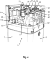
Figure 4 is another enlarged perspective view of the top part of the indoor unit offigure 2 ; -
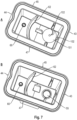
Figures 5A-B are perspective views of a separation box; -
Figure 6 is a cross-sectional view along the line 6-6 infigure 5B ; -
Figures 7A-B are perspective top views of the lower part of the separation box; -
Figure 8 is a prospective bottom view of the upper part of the separation box; -
Figures 9A-B are a perspective view and an exploded view of a gas sensor box. - It is to be understood that same reference numerals designate same or similar features throughout the drawings and the description. Same or similar features in the different embodiments are only described once in order to avoid repetition.
- The hydro split heat pump as shown in
figure 1 comprises a refrigerant circuit. The entire refrigerant circuit is arranged outside of a building 1, such as a residential house or commercial building. - The
refrigerant circuit 10, in its most general configuration, connects a heatsource heat exchanger 12, anexpansion valve 14, a usageside heat exchanger 16 and acompressor 18. It is to be understood that therefrigerant circuit 10 may comprise further components as it is well known in the art. - A refrigerant is circulated in the
refrigerant circuit 10 by means of thecompressor 18. The refrigerant may be a flammable refrigerant such as R290 (propane). The heat source may be air so that the heat pump may also be called an air-source heat pump. Yet, the heat pump may use a different source, for example a ground source heat pump using heat from soil or groundwater. - The usage
side heat exchanger 16 may be a plate or double plate heat exchanger. - At least the above-described components of the refrigerant circuit, preferably all components of the refrigerant circuit may be located in an outdoor unit housing 2 of an outdoor unit.
- The heat pump further comprises a
heat medium circuit 20. The heat medium circuit comprises at least the usageside heat exchanger 16, apump 22 and aload 29 connected by heat medium piping. The heat medium may be water so that the heat pump is an air to water heat pump. - The
load 29 may be a domestic hot water tank, a floor heating and/or a radiator. - The
heat medium circuit 20 further comprises abooster heater 24 and amagnetic filter 26. Thebooster heater 24 comprises a second air purge valve 25 (seefigures 3 and4 ). Themagnetic filter 26 comprises a firstair purge valve 27 and a pressure relief valve 28 (seefigures 3 and4 ). Air purge valves are used to automatically purge air (gaseous medium) from the heat medium circuit. Air purge valves are generally mounted vertically and preferably at the top of thebooster heater 24 and themagnetic filter 26. A pressure relief valve is a type of safety valve used to control or limit the pressure in the heat medium circuit. Otherwise, excessive pressure might build up and create equipment failure. Also thepressure relief valve 28 is mounted at the top of themagnetic filter 26. - In the present embodiment, the
pump 22, thebooster heater 24 including theair purge valve 25, themagnetic filter 26 including theair purge valve 27 and thepressure relief valve 28 are accommodated in an indoor unit housing 3. In particular, the indoor unit 4 may, as in the present embodiment, be divided into amachine chamber 5 located in a top portion of the indoor unit 4 and atank chamber 6 in a bottom portion of the indoor unit 4. The components of theheat medium circuit 20 are primarily accommodated in themachine chamber 5. The indoor unit housing 3 comprises lateral side walls including afront wall 6, right and leftside walls 7 and aback wall 8. - Heat medium connection piping 30, 31 connect the indoor unit 4 to the outdoor unit. Accordingly, heat may be transferred between the refrigerant circulated in the
refrigerant circuit 10 and heat medium (here water) circulated in theheat medium circuit 20. - In case leakage occurs in the usage
side heat exchanger 16, refrigerant from therefrigerant circuit 10 may enter theheat medium circuit 20. The refrigerant will, therefore likely be in the gaseous state and be entrained in the liquid heat medium. The refrigerant being gaseous may thus leave the heat medium circuit via theair purge valves heat medium circuit 20, via thepressure relief valve 28. - The indoor unit housing 3, particularly the
machine chamber 5, also accommodates electric and/or electronic equipment such as a control board, the pump, electric valves, etc. Such equipment is a potential ignition source. Hence, if a flammable gaseous refrigerant were to be released inside the indoor unit housing 3, particularly themachine chamber 5, it could be ignited by these ignition sources causing a hazardous event. - For this reason, the present disclosure suggests a
separation box 40. - The
separation box 40 has a boxed shapedbody 46. Theseparation box 40, or more particularly itsbody 46, has a top 41 (top wall), a bottom 42 (bottom wall), oppositelateral side walls front wall 47 and aback wall 45. The oppositelateral side walls back wall 45 and thefront wall 47 respectively connect the bottom 42 and the top 41. Thebody 46 may be an integral one-piece injection molded product. Yet, in the present embodiment, thebody 46 is made of two parts, alower part 90 and anupper part 91. In this embodiment, thebody 46 is separated along a horizontal separation line 92. - The
separation box 40 defines aspace 48. Thespace 48 is delimited by the top 41, the bottom 42, thelateral side walls front wall 47 and theback wall 45. The volume of thespace 48 is between 0.15L and 0.75L. - The
space 48 has afirst gas inlet 52 and asecond gas inlet 53. Further, thespace 48 has adrain inlet 54 and adrainage port 55. - The
first gas inlet 52 is connected to theair purge valve 25 of thebooster heater 24 by means of a first preferablyflexible tubing 75. - The
second gas inlet 53 is connected to theair purge valve 27 of themagnetic filter 26 by second preferablyflexible tubing 76. - The
drain inlet 54 is connected to thepressure relief valve 28 of themagnetic filter 26 by a third optionallyflexible tubing 77. - To put it differently, the first and
second gas inlets drain inlet 54 are integrally formed as ports with thebody 46, preferably theupper portion 91. The first andsecond gas inlets drain inlet 54 fluidly communicate thespace 48 with the respective outlets of theair purge valves pressure relief valve 28. - The first and
second gas inlets back wall 45, thefront wall 47 or thelateral side walls first gas inlet 52 is located in the top 41, whereas thesecond gas inlet 53 is located in theback wall 45. - The
drain inlet 54 may be located in any of the top 41, theback wall 45, thefront wall 47 or thelateral side walls drain inlet 54 is located in thefront wall 47 and hence in a wall opposite to the wall at which thesecond gas inlet 53 is located. - The
drainage port 55 is arranged in the bottom 42. Further, thedrainage port 55 may be integrally formed with thebody 46, preferably itslower part 90. - For sealing the
separation box 40, thelower part 90 and theupper part 91 may be welded to each other. For this purpose, thelower part 90 and theupper part 91 may each have acircumferential rim circumferential rim 49 of thelower part 90 has agroove 51 and thecircumferential rim 50 of theupper part 91 has a corresponding protrusion 61 (seefigure 6 ). Upon placing theupper part 91 on thelower part 90, theprotrusion 61 engages with thegroove 51. Subsequently thelower part 90 and theupper part 91 are welded together, preferably using ultrasonic welding, in the area of thecircumferential rims 59, 50. - Alternatively, the
lower part 90 may have a circumferential rim whereas theupper part 91 may have a circumferential groove. In order to attach the twoparts parts lower part 90, whereby the sealing is pressed in the circumferential groove. - The
drain inlet 54 and thedrainage port 55 may be circular in cross section. The diameter of thedrain inlet 54 may be equal to or smaller than the diameter of thedrainage port 55. - The
body 46 of theseparation box 40 further has agas outlet 60 which may be integrally formed as port with thebody 46. Thegas outlet 60 may be located in any of the top 41, the bottom 42, theback wall 45, thefront wall 47 or thelateral side walls gas outlet 60 is located in the bottom 42. - The
drain inlet 54 is arranged in a side wall of theseparation box 40 adjacent to the top 41. In the present embodiment, thedrain inlet 54 is arranged in thefront wall 47. Abaffle plate 80 extends from the top 41 into thespace 48 facing thedrain inlet 54 to deflect liquid introduced into thespace 48 via thedrain inlet 54 away from thedrainage port 55. - As can be best seen from
figure 8 , thebaffle plate 80 is in the present embodiment integrally formed with theupper part 91. Thebaffle plate 80 may in a horizontal cross section (that is in a cross-section parallel to the centre axis of thedrain inlet 54 and the bottom) be partly circular connecting at two opposite ends 81 to thefront wall 47 of theupper part 91. Thus, thebaffle plate 80 may be integrally formed with thebody 46, particularly theupper part 91. As a result, any liquid introduced via thedrain inlet 54 is deflected by approximately 90 degrees towards the bottom 42 and parallel to or along the inner surface of thefront wall 47. - A
first wall 62 is arranged in thespace 48 of theseparation box 40. Thefirst wall 62 is, in the present embodiment, integrally formed with thelower part 90 of thebody 46. Thefirst wall 62 extends from the bottom 42 towards the top 41 separating thespace 48 of theseparation box 40 into afirst space 64 into which thedrain inlet 54 opens and in which thedrainage port 55 is located, and asecond space 65 in which thegas outlet 60 is located, wherein thefirst space 64 andsecond space 65 are fluidly communicated, particularly via apassage 66. - A
second wall 63 is arranged in thespace 48 of theseparation box 40. Thesecond wall 63 is, in the present embodiment, integrally formed with theupper part 91 of thebody 46. Thesecond wall 63 extends from the top 41 towards the bottom 42. Thefirst wall 62 and thesecond wall 63 overlap in a direction perpendicular to their extension direction with a distance between thefirst wall 62 and thesecond wall 63 forming thepassage 66 to fluidly communicate thefirst space 64 and thesecond space 65. in this context, the extension direction is in the present embodiment an up-and-down, i.e. a vertical direction, whereas a direction perpendicular thereto is a right-to-left direction, i.e. a horizontal direction. - Moreover, a floating
valve 100 is provided with respect to thedrainage port 55. The floatingvalve 100 comprises afloat ball 101 adapted in diameter to fit into and seal an inlet opening of thedrainage port 55. - The floating
valve 100 further comprisesvertical ribs 102 to provide a guide for thefloat ball 101 in the horizontal direction. Hence, movement of thefloat ball 101 in the horizontal direction is restricted so that the ball may only float in a substantially vertical direction (away from the drainage port 55). - A circumferential
annular ridge 93 is provided on the bottom 42 circumventing the inlet opening of thedrainage port 55. Theridge 93 protrudes from the bottom 42 towards the top 41. Thefloat ball 101 sits ontop 94 of theridge 93. Thefloat ball 101 and the top 94 of theridge 93 make a line contact (linear contact) particularly an annular line contact (linear contact). - Further, the
ridge 93, starting from the top 94 slopes radially outward. To put it differently, the outer diameter of theridge 93 is smaller at the top 94 than at the bottom 42. - Further, a
stop 103 is located at the top of thevertical ribs 102 as a stop for theball 101 in the vertical direction. To put it differently, thestop 103 restricts the movement of theball 101 in the vertical direction. In the present embodiment, thestop 103 is configured as, preferably cylindrical, protrusion extending from the top 41 towards the bottom 42. In the embodiment, thestop 103 is integrally formed with thebody 46, particularly itsupper part 91. A reinforcingwall 104 connects thestop 103 to theback wall 45. - An outlet line (tube) is connected to the
gas outlet 60 connecting thegas outlet 60 to the outside of themachine chamber 5 and optionally the indoor unit 2. Agas sensor box 121 is located in the indoor unit 2, particularly themachine chamber 5 thereof. The gas sensor box 121 (seefigures 3 ,4 and9 ) is arranged in the outlet line. The outlet line may comprise a fourth, preferably flexible,tubing 118 connecting thegas outlet 60 to thegas sensor box 121 and a fifth, preferably flexible,tubing 127 connecting thegas sensor box 121 to the outside of themachine chamber 5 and optionally the indoor unit 2. - The
gas sensor box 121 comprises afirst half 122 and asecond half 123 defining asensing space 124. Thesensor box 121 further comprises afirst connection port 125 connected to the fourthflexible tubing 118 and asecond connection port 126 connected to the fifthflexible tubing 127. Thefirst connection port 125 may be integrally formed with thefirst half 122 and thesecond connection port 126 may be integrally formed with thesecond half 123. - In order to mount the
sensor box 121 in themachine chamber 5 of the indoor unit 2, thesensor box 121 further comprises fixing means 130. - A
gas sensor 120 is located in thesensing space 124. Thegas sensor 120 is electrically connected to a controller. The electrical lines connecting thegas sensor 120 and the controller pass through anopening 128 in a wall of thegas sensor box 121 by means of a grommet. - A flow restrictor 129 (here a straight wall) is located in the
sensing space 124 facing an inlet opening of thefirst connection port 125 redirecting the flow direction of gas flowing into thesensing space 124 so as to reduce the flow rate and allow gaseous refrigerant to remain in thesensing space 124 for a certain period. - In the following, the function of the embodiment is explained in more detail.
- In normal operation, in which no leakage of refrigerant from the refrigerant circuit to the heat medium circuit occurs, air may be released from the first and second
air purge valves flexible tubing second gas inlets space 48 of theseparation box 40 without being discharged into the interior of the indoor unit housing 3, particularly themachine chamber 5. The air is then released from theseparation box 40 via thegas outlet 60. - The gas is subsequently flown via the fourth
flexible tubing 118 to thesensor box 121 and from thesensor box 121 via the fifthflexible tubing 127 to the outside of themachine chamber 5 of the indoor unit 2. - Further, in case of a pressure increase above a certain threshold, air and liquid heat medium may be released from the
pressure relief valve 28. The air and the liquid heat medium are guided via the thirdflexible tubing 77 and thedrain inlet 54 into thespace 48. - As the
drain inlet 54 is oriented facing thebaffle plate 80, the liquid heat medium entraining the air will collide with thebaffle plate 80 assisting the separation of air and liquid heat medium. - In addition, the flow direction of the liquid introduced into the
space 48 via thedrain inlet 54 is changed from a first direction (here horizontal direction) to a second direction (here vertical direction) along one of the walls of the body 46 (here the front wall 47). Hence, the float valve is prevented from being forcibly closed by new liquid heat medium being introduced via thedrain inlet 54. - In any case, the liquid eventually reaches the bottom 42 of the
space 48 without hitting thefloat ball 101. Some of the liquid heat medium may flow along the inclined portion of the bottom 42 towards thedrainage port 55. With an increasing level of liquid heat medium in thespace 48, particularly thefirst space 64, liquid heat medium may seal an interface between theridge 93 and thefloat ball 101 enhancing the sealing properties. Thefirst wall 62 and the inclination of the bottom 42 further prevent liquid heat medium from reaching thegas outlet 60. - Once the level of the liquid heat medium becomes higher than the top 94 of the
ridge 93, thefloat ball 101 is lifted from the valve seat (the top 94 of the ridge 93) in a vertical direction. During this movement, the fourribs 102, provided diametrically opposite to each other, guide thefloat ball 101 in the vertical direction restricting its possible movement in a horizontal direction. Thus, any liquid heat medium reaching the bottom 42 is not automatically drained via thedrainage port 55. Rather, a certain amount of liquid medium needs to be present near the inlet opening of thedrainage port 55 in order to float thefloat ball 101 and open the inlet opening of thedrainage port 55. - Upon lifting the
float ball 101 from the valve seat, liquid heat medium may be drained via the inlet opening of thedrainage port 55 so that the liquid heat medium is drained from theseparation box 40 via the drainage line 56 outside themachine chamber 5 if the indoor unit and potentially the indoor unit 2. - In case a leakage occurs in the usage
side heat exchanger 16 and gaseous refrigerant enters the heat medium circuit, the gaseous refrigerant may exit the heat medium circuit again via the first and secondair purge valves pressure relief valve 28. As the air, the gaseous refrigerant may then also be exhausted from theseparation box 40 and the indoor unit housing 3 via thegas outlet 60, the fourthflexible tubing 118, thesensor box 121 and the fifthflexible tubing 127. - Because the liquid heat medium enters via the
drain inlet 54 and collides with thebaffle plate 80 gaseous refrigerant may reliably be separated from the liquid heat medium in order to prevent refrigerant from being drained via thedrainage port 55 but rather be vented via thegas outlet 60. In particular, any gaseous refrigerant in thefirst space 64 may flow into thesecond space 65 via thepassage 66 between thefirst wall 62 and thesecond wall 63. - In addition, due to the separation of the
space 48 into thefirst space 64 in which thedrainage port 55 and thedrain inlet 54 are located and thesecond space 65 in which the first andsecond gas inlets gas outlet 60 are located, discharging of the gaseous refrigerant via thedrainage port 55 can be minimized. This is further assisted by the provision of thefloat valve 100. - Due to the connection of the
gas sensor box 121 to thegas outlet 60, any gaseous refrigerant discharged from theseparation box 40 via thegas outlet 60 accumulates inside thesensing space 124. The flow rate of gaseous refrigerant flowing into thesensor box 121 is decelerated by theflow restrictor 129 so that the gas remains in thesensing space 124 for an appropriate time. As a result, thegas sensor 120 can sense the gaseous refrigerant and communicate it to the controller of the heat pump which can initiate countermeasures and/or measures for informing the user as it is known in the art. - In any of the above embodiments, the
separation box 40 enables to securely guide any gaseous refrigerant that has been leaked into the heat medium circuit and which would otherwise be released into the interior of the indoor unit housing 3 to the outside of the indoor unit housing 3 or at least themachine chamber 5 thereof. Therefore, the risk of the gaseous refrigerant being ignited by an ignition source also located inside the indoor unit housing 3 can reliably be prevented. - It is to be understood that the various features of the above-described embodiments can also be combined unless in contradiction.
Reference Sign List building 1 outdoor unit housing 2 indoor unit housing 3 indoor unit 4 machine chamber 5 front wall 6 left and right side walls 7 back wall 8 tank chamber 9 refrigerant circuit 10 heat source heat exchanger 12 expansion valve 14 usage side heat exchanger 16 compressor 18 heat medium circuit 20 pump 22 booster heater 24 second air purge valve 25 magnetic filter 26 first air purge valve 27 pressure relief valve 28 load 29 connection piping 30, 31 separation box 40 top 41 bottom 42 opposite lateral side walls 43, 44 back wall 45 boxed shaped body 46 front wall 47 space 48 circumferential rim 49 circumferential rim 50 groove 51 first gas inlet 52 second gas inlet 53 drain inlet 54 drainage port 55 drainage line 56 gas outlet 60 protrusion 61 first wall 62 second wall 63 first space 64 second space 65 passage 66 first flexible tubing 75 second flexible tubing 76 third flexible tubing 77 baffle plate 80 opposite ends 81 lower part 90 upper part 91 horizontal separation line 92 ridge 93 top of the ridge 94 floating valve 100 float ball 101 vertical ribs 102 stop 103 reinforcing wall 104 fourth flexible tubing 118 gas sensor 120 gas sensor box 121 first half 122 second half 123 sensing space 124 first connection port 125 second connection port 126 fifth flexible tubing 127 opening 128 flow restrictor 129 fixing means 130
Claims (15)
- Heat pump comprisinga refrigerant circuit (10) connecting a heat source heat exchanger (12), an expansion valve (14), a usage side heat exchanger (16) and a compressor (18), the refrigerant circuit being accommodated in an outdoor unit housing (2); anda heat medium circuit (20) connecting the usage side heat exchanger (16), a pump (22) and a load (29), the heat medium circuit further comprising a pressure relief valve (28) accommodated in a machine chamber in an indoor unit housing (3) and having an outlet for releasing gas and/or liquid heat medium from the heat medium circuit,characterized bya separation box (40) located in the machine chamber in the indoor unit housing (3) having a bottom (42) and a top (41) and defining a space (48), the separation box (40) comprisinga drain inlet (54) into the space (48), the outlet of the pressure relief valve (28) being connected to the drain inlet (54),a drainage port (55) arranged in the bottom (42) of the separation box (40) for draining liquid from the space (48) to the outside of the machine chamber in the indoor unit housing (3), anda gas outlet (60) for discharging gas from the space (48) to the outside of the machine chamber in the indoor unit housing (3).
- Heat pump according to claim 1, wherein the bottom (42) is inclined towards the drainage port (55).
- Heat pump according to claim 1 or 2, wherein a float valve (100) is arranged in the drainage port (55).
- Heat pump according to claim 3, wherein the float valve (100) is a guided float ball (101).
- Heat pump according to claim 4, wherein the drainage port (55) has an inlet opening and a ridge (93) circumventing the inlet opening, wherein the float ball (101) sits on a top (94) of the ridge (93).
- Heat pump according to claim 5, wherein the ridge (93), starting from the top (94), slopes radially outward.
- Heat pump according to claim 5 or 6, wherein the top (94) of the ridge (93) and the float ball (101) are configured to make linear contact.
- Heat pump according to any one of the preceding claims, wherein the drain inlet (54) is arranged in a side wall of the separation box (40) adjacent to the top (41), wherein a baffle plate (80) in the space (48) faces the drain inlet (54) to deflect liquid introduced into the space (48) via the drain inlet (54) away from the drainage port (55).
- Heat pump according to any one of the preceding claims, wherein a first wall (62) is arranged in the space (48) of the separation box (40) and extends from the bottom (42) towards the top (41) separating the space (48) of the separation box (40) into a first space (64) into which the drain inlet (54) opens and in which the drainage port (55) is located, and a second space (65) in which the gas outlet (60) is located, wherein the first space and second space are fluidly communicated.
- Heat pump according to claim 9, wherein a second wall (63) is arranged in the space (48) of the separation box (40) and extends from the top (41) towards the bottom (42), the first wall (62) and the second wall (63) overlap in a direction perpendicular to their extension direction with a distance between the first wall and the second wall to fluidly communicate the first space (64) and the second space (65) .
- Heat pump according to any one of the preceding claims, wherein the heat medium circuit (20) further comprises a magnetic filter (26) having the pressure relief valve (28).
- Heat pump according to claim 11, wherein the magnetic filter (26) further has a first air purge valve (27), the first air purge valve (27) having a first outlet for releasing at least gas from the heat medium circuit (20), the first air purge valve (27) being accommodated in the machine chamber in the indoor unit housing (3), wherein the separation box (40) has a first gas inlet (53) connected to the first outlet of the first air purge valve (27).
- Heat pump according to any one of the preceding claims, wherein the heat medium circuit (20) further comprises a booster heater (24) having a second air purge valve (25), the second air purge valve (25) having a second outlet for releasing at least gas from the heat medium circuit (20), the second air purge valve (25) being accommodated in the machine chamber in the indoor unit housing (3), wherein the separation box (40) has a second gas inlet (52) connected to the second outlet of the second air purge valve (25).
- Heat pump according to claims 11 and 13 or 12 and 13, wherein the separation box is located in the machine chamber in the indoor unit housing (3) closer to the magnetic filter (26) than to the booster heater (24).
- Heat pump according to any one of the preceding claims, further comprising a gas sensor (120) arranged in a gas outlet line (118, 127) connected to the gas outlet (60) of the separation box (40) for sensing gaseous refrigerant in the gas outlet line.
Priority Applications (1)
| Application Number | Priority Date | Filing Date | Title |
|---|---|---|---|
| EP23219888.7A EP4575329A1 (en) | 2023-12-22 | 2023-12-22 | Heat pump |
Applications Claiming Priority (1)
| Application Number | Priority Date | Filing Date | Title |
|---|---|---|---|
| EP23219888.7A EP4575329A1 (en) | 2023-12-22 | 2023-12-22 | Heat pump |
Publications (1)
| Publication Number | Publication Date |
|---|---|
| EP4575329A1 true EP4575329A1 (en) | 2025-06-25 |
Family
ID=89322138
Family Applications (1)
| Application Number | Title | Priority Date | Filing Date |
|---|---|---|---|
| EP23219888.7A Pending EP4575329A1 (en) | 2023-12-22 | 2023-12-22 | Heat pump |
Country Status (1)
| Country | Link |
|---|---|
| EP (1) | EP4575329A1 (en) |
Citations (8)
| Publication number | Priority date | Publication date | Assignee | Title |
|---|---|---|---|---|
| WO1996016299A1 (en) * | 1994-11-17 | 1996-05-30 | Carlsson Bjoern | A method and a device for reducing any buildup of corrosion accumulations in a conduit circuit for a continuous flow of a system liquid |
| EP3598039A1 (en) * | 2017-03-15 | 2020-01-22 | Mitsubishi Electric Corporation | Heat pump device and installation method therefor |
| EP3693670A1 (en) * | 2019-02-08 | 2020-08-12 | Panasonic Intellectual Property Management Co., Ltd. | Heat pump system |
| WO2021160221A1 (en) * | 2020-02-13 | 2021-08-19 | Viessmann Werke Gmbh & Co Kg | Heat pump system and method for operating a heat pump system of this type |
| EP3967943A1 (en) * | 2020-09-14 | 2022-03-16 | Panasonic Intellectual Property Management Co., Ltd. | Heat medium circulation system |
| EP4047288A1 (en) * | 2021-02-18 | 2022-08-24 | Panasonic Intellectual Property Management Co., Ltd. | Heat medium circulation system |
| WO2023095427A1 (en) * | 2021-11-29 | 2023-06-01 | パナソニックIpマネジメント株式会社 | Heat medium circulation system |
| SK1352023U1 (en) * | 2023-08-07 | 2023-12-21 | Protherm Production S.R.O. | Degassing device |
-
2023
- 2023-12-22 EP EP23219888.7A patent/EP4575329A1/en active Pending
Patent Citations (8)
| Publication number | Priority date | Publication date | Assignee | Title |
|---|---|---|---|---|
| WO1996016299A1 (en) * | 1994-11-17 | 1996-05-30 | Carlsson Bjoern | A method and a device for reducing any buildup of corrosion accumulations in a conduit circuit for a continuous flow of a system liquid |
| EP3598039A1 (en) * | 2017-03-15 | 2020-01-22 | Mitsubishi Electric Corporation | Heat pump device and installation method therefor |
| EP3693670A1 (en) * | 2019-02-08 | 2020-08-12 | Panasonic Intellectual Property Management Co., Ltd. | Heat pump system |
| WO2021160221A1 (en) * | 2020-02-13 | 2021-08-19 | Viessmann Werke Gmbh & Co Kg | Heat pump system and method for operating a heat pump system of this type |
| EP3967943A1 (en) * | 2020-09-14 | 2022-03-16 | Panasonic Intellectual Property Management Co., Ltd. | Heat medium circulation system |
| EP4047288A1 (en) * | 2021-02-18 | 2022-08-24 | Panasonic Intellectual Property Management Co., Ltd. | Heat medium circulation system |
| WO2023095427A1 (en) * | 2021-11-29 | 2023-06-01 | パナソニックIpマネジメント株式会社 | Heat medium circulation system |
| SK1352023U1 (en) * | 2023-08-07 | 2023-12-21 | Protherm Production S.R.O. | Degassing device |
Similar Documents
| Publication | Publication Date | Title |
|---|---|---|
| US12553629B2 (en) | Heat pump and method for installing the same | |
| US9194606B2 (en) | Water-heater, a combination of a top cover and bottom tray for a water heater, and a bottom cover | |
| KR102512534B1 (en) | Humidifier included in air conditioner | |
| WO2024252882A1 (en) | Hot water system with heat pump | |
| KR101876200B1 (en) | Gas boiler exhaust block equipment | |
| CN220911565U (en) | Air treatment unit | |
| EP4467900A1 (en) | Indoor unit and heat pump | |
| EP4575351A1 (en) | Heat pump | |
| EP4467885A1 (en) | Indoor unit and heat pump | |
| CN218033413U (en) | Air conditioner | |
| KR20130007113U (en) | Coupler for drain hose of air conditioner | |
| TWI660099B (en) | Gas blocking device for pipeline | |
| CN222937903U (en) | An air conditioner | |
| CN219160747U (en) | High tightness refrigerator inner container assembly | |
| WO2024245896A1 (en) | Indoor unit and heat pump | |
| CN222012111U (en) | Cabinet air conditioner | |
| JP3564553B2 (en) | Floor heating system | |
| KR200397304Y1 (en) | An apparatus for preventing a condensate backward in the air conditioner | |
| CN121230049A (en) | An air conditioner | |
| WO2025044225A1 (en) | Air conditioner | |
| CN118310094A (en) | Integral air conditioner | |
| WO2021221512A1 (en) | A water heater | |
| CN119934584A (en) | Air handling units | |
| CN119901005A (en) | A duct machine | |
| JP2002195585A (en) | Floor heating system |
Legal Events
| Date | Code | Title | Description |
|---|---|---|---|
| PUAI | Public reference made under article 153(3) epc to a published international application that has entered the european phase |
Free format text: ORIGINAL CODE: 0009012 |
|
| STAA | Information on the status of an ep patent application or granted ep patent |
Free format text: STATUS: THE APPLICATION HAS BEEN PUBLISHED |
|
| AK | Designated contracting states |
Kind code of ref document: A1 Designated state(s): AL AT BE BG CH CY CZ DE DK EE ES FI FR GB GR HR HU IE IS IT LI LT LU LV MC ME MK MT NL NO PL PT RO RS SE SI SK SM TR |
|
| STAA | Information on the status of an ep patent application or granted ep patent |
Free format text: STATUS: REQUEST FOR EXAMINATION WAS MADE |
|
| 17P | Request for examination filed |
Effective date: 20250801 |