BACKGROUND ART
-
The present invention relates to an air jet loom.
-
For example, a jet loom is disclosed in
Japanese Patent Application Publication No. 2003-239160 , and the jet loom is an air jet loom including a profile reed, a sley, and a machine frame including an air tank. In addition, in the Publication, the jet loom as the air jet loom includes a main nozzle for weft insertion and sub nozzles for the weft insertion as air nozzles, electromagnetic valves, and flexible tubes as supply tubes.
-
The profile reed is provided upright from the sley, and the main nozzle for the weft insertion and the sub nozzles for the weft insertion are attached to the sley. The electromagnetic valves are attached to the air tank. The main nozzle for the weft insertion and the sub nozzles for the weft insertion are each connected to the corresponding electromagnetic valve that controls supply of air through the flexible tube.
-
In the air jet loom, a weft yarn injected from the main nozzle for the weft insertion is propelled by relay jets of the sub nozzles for the weft insertion to travel through a weft insertion passage as a weft passage formed in the profile reed. The inserted weft yarn is beaten by the profile reed that swings together with the sley.
-
The profile reed beats the weft yarn by the swinging of the sley. That is, in the beating of the weft yarn, the air nozzles supported on the sley also swing. The electromagnetic valve connected to the corresponding air nozzle is attached to a portion of the air jet loom such as the machine frame, which does not swing during the beating. Accordingly, each of the supply tubes connected to the corresponding air nozzle is swung by the swinging of the air nozzle toward a direction in which the profile reed swings.
-
Thus, a load is applied on each of the supply tubes through which air is supplied to the corresponding air nozzle, by the swinging of the air nozzle. The load applied on the supply tube may lead to breakage of the supply tube. In the air jet loom, it has been desired to reduce the load on the supply tube caused by the swinging of the air nozzle.
SUMMARY
-
In accordance with an aspect of the present invention, there is provided an air jet loom that includes a sley extending in a direction in which a weft yarn is inserted, the sley supporting a reed, an air nozzle being supported on the sley, an electromagnetic valve being supported on a machine frame; and a supply tube connecting the air nozzle to the electromagnetic valve. The reed beats the weft yarn by swinging together with the sley. The supply tube has a bending portion formed in advance.
-
Other aspects and advantages of the invention will become apparent from the following description, taken in conjunction with the accompanying drawings, illustrating by way of example the principles of the invention.
BRIEF DESCRIPTION OF THE DRAWINGS
-
The invention, together with objects and advantages thereof, may best be understood by reference to the following description of the embodiments together with the accompanying drawings in which:
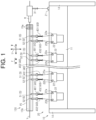
- FIG. 1 is a schematic view illustrating an air jet loom;
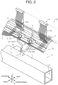
- FIG. 2 is a perspective view illustrating a part of the air jet loom;
- FIG. 3 is a side view illustrating a part of the air jet loom;
- FIG. 4 is a perspective view illustrating a part of the air jet loom;
- FIG. 5 is a perspective view illustrating a sub nozzle supply tube;
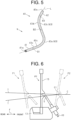
- FIG. 6 is a schematic view illustrating a first posture, a reference posture, and a second posture of a reed; and
- FIG. 7 is a perspective view illustrating a part of another air jet loom.
DETAILED DESCRIPTION OF THE EMBODIMENTS
-
The following will describe an embodiment of an air jet loom according to the present invention with reference to FIG. 1 to FIG. 6.
<Air jet loom>
-
As illustrated in FIGS. 1, 2, and 3, an air jet loom 100 includes a machine frame 10 and a weft insertion device 20. The machine frame 10 includes an air tank 11 and a pair of side frames 14.
-
The air jet loom 100 has a rocking shaft 12, a sley 13, and a reed 15 provided on the sley 13. In the air jet loom 100, the weft insertion device 20 causes a weft yarn Y to travel in a weft insertion direction W to perform weft insertion. A width direction of the air jet loom 100 coincides with the weft insertion direction W. The air jet loom 100 weaves a fabric C by beating the inserted weft yarn Y with the reed 15. The woven fabric C is formed of the weft yarns Y and warp yarns T extending in a front-rear direction F perpendicular to the weft insertion direction W. In the air jet loom 100, an up-down direction U is a direction perpendicular to the weft insertion direction W and the front-rear direction F. Hereinafter, in the weft insertion direction W, a side toward which the weft yarn Y travels is referred to as a "downstream" side and the opposite side of the downstream side is referred to as an "upstream" side. That is, the weft yarn Y travels in the weft insertion direction W from the upstream side toward the downstream side. In addition, in the front-rear direction F, a side on which the woven fabric C is wound is referred to as a "front" side, and the opposite side of the front side across the air jet loom 100 is referred to as a "rear" side.
<Machine frame>
-
As illustrated in FIGS. 1 and 2, the air tank 11 has an elongated shape whose longitudinal side extends in the width direction of the air jet loom 100. That is, the air tank 11 extends in the weft insertion direction W. Opposite end portions of the longitudinal side of the air tank 11 are each supported by a corresponding one of the side frames 14. The air tank 11 is supported by the pair of side frames 14 away from each other in the width direction of the air jet loom 100 and extends between them. The air tank 11 extends in the width direction of the air jet loom 100 and serves as a beam material of a loom frame fixed to a floor.
-
The air tank 11 that serves as the beam material extending between the pair of side frames 14 has a hollow as an air storage space. Specifically, a tank chamber 11a is formed inside the air tank 11. Compressed air is supplied from a pressure supply source, which is not illustrated, to the air tank 11, and stored in the tank chamber 11a.
<Rocking shaft, sley, and reed>
-
As illustrated in FIG. 3, the rocking shaft 12 has a cylindrical shape extending in the width direction of the air jet loom 100. That is, the rocking shaft 12 extends in the weft insertion direction W. The rocking shaft 12 is supported by the pair of side frames 14 and extends between them. The rocking shaft 12 is supported by the pair of side frames 14 at opposite ends of the rocking shaft 12 in a direction in which the rocking shaft 12 extends through bearings, such that the rocking shaft 12 is turnable around an axis of the rocking shaft 12. Illustrations of the bearings are omitted. The axis of the rocking shaft 12 extending in the weft insertion direction W serves as a rotation axis, and the rocking shaft 12 turns with respect to the pair of side frames 14.
-
The rocking shaft 12 has an arm 12a extending upward in the up-down direction U of the air jet loom 100, and the arm 12a is integrally provided with the rocking shaft 12. The sley 13 is supported on an upper end of the arm 12a. The sley 13 extends in the width direction of the air jet loom 100. That is, the sley 13 extends in the weft insertion direction W of the weft yarn Y The sley 13 turns integrally with the rocking shaft 12. When the rocking shaft 12 turns with respect to the pair of side frames 14, the sley 13 swings in the front-rear direction F. The sley 13 is located on an upper side of the air tank 11 in the up-down direction U and on a rear side of the air tank 11 in the front-rear direction F.
-
As illustrated in FIGS. 1 and 2, the air jet loom 100 includes the reed 15. The reed 15 is supported on the sley 13. A lower end of the reed 15 is fixed to the sley 13. In other words, the sley 13 supports the reed 15. The reed 15 is formed of a plurality of reed dents 15a arranged in a row in the weft insertion direction W. That is, the plurality of reed dents 15a is arranged in the width direction of the air jet loom 100. Note that FIG. 3 illustrates only one of the plurality of reed dents 15a.
-
As illustrated in FIGS. 1 and 2, the plurality of reed dents 15a is arranged with a distance in the weft insertion direction W on the sley 13. The lower end of each of the reed dents 15a is fixed to the sley 13, so that the reed dents 15a are supported on the sley 13. In other words, the reed 15 has a plurality of spaces in the weft insertion direction W. The warp yarns T each pass through a corresponding one of the spaces.
-
The reed 15 has therein a weft passage 15b. In other words, the weft passage 15b is formed in the reed 15. The weft passage 15b in the reed 15 extends in the weft insertion direction W of the air jet loom 100. That is, the weft passage 15b in the reed 15 extends in a direction in which the reed dents 15a are arranged. The weft passage 15b in the reed 15 is open at opposite ends of the reed 15 in the direction in which the reed dents 15a are arranged.
-
The reed 15 swings in the front-rear direction F together with the sley 13 by the rocking shaft 12. The reed 15 beats the weft yarn Y by swinging together with the sley 13. In other words, the air jet loom 100 beats the weft yarn Y by swinging the reed 15 in the front-rear direction F. As illustrated in FIG. 6, the sley 13 swings in a range between a position in which the reed 15 is in a first posture P1 and a position in which the reed 15 is in a second posture P2. In FIG. 6, the reed 15 in the first posture P1 and a sub nozzle S are illustrated by a long dashed short dashed line, and the reed 15 in the second posture P2 and the sub nozzle S are illustrated by a long dashed double-short dashed line. The reed 15 swings in a circumferential direction of the rocking shaft 12. When the reed 15 is in the second posture P2, the reed 15 comes into contact with a cloth fell C1. When the reed 15 comes into the second posture P2 with the weft yarn Y traveling through the weft passage 15b in the reed 15, the weft yarn Y is beaten. The position of the sley 13 in which the reed 15 is in the first posture P1 is the rearmost position in the front-rear direction F away from the position in which the reed 15 is in the second posture P2 within the range in which the sley 13 swings. In other words, the sley 13 swings within the range between the position in which the reed 15 is in the first posture P1 and the position where the reed 15 is in the second posture P2.
<Weft insertion device>
-
As illustrated in FIG. 1, the weft insertion device 20 includes a main nozzle M, the sub nozzles S as the air nozzles, a first electromagnetic valve 21, and second electromagnetic valves 22 as the electromagnetic valves
<Main nozzle and first electromagnetic valve>
-
The main nozzle M is provided on the sley 13. That is, the sley 13 supports the main nozzle M. Thus, the main nozzle M swings in the front-rear direction F together with the sley 13. The main nozzle M is located on the most upstream side in the weft insertion direction W on the sley 13. More specifically, the main nozzle M is located upstream of the reed 15 in the weft insertion direction W on the sley 13.
-
Air supplied from the pressure supply source, which is not illustrated, is discharged from the main nozzle M, so that the weft yarn Y is injected into the weft passage 15b in the reed 15. That is, the main nozzle M inserts the weft yarn Y into the weft passage 15b formed in the reed 15. The weft yarn Y injected into the weft passage 15b in the reed 15 travels in the weft insertion direction W through the weft passage 15b in the reed 15. That is, the air jet loom 100 inserts the weft yarn Y into the weft passage 15b in the reed 15 by the main nozzle M. The weft insertion direction W is also referred to as a direction in which the weft yarn Y injected from the main nozzle M travels.
-
The main nozzle M is connected to the pressure supply source, which is not illustrated, through the first electromagnetic valve 21. The first electromagnetic valve 21 is provided on the machine frame 10. For example, the first electromagnetic valve 21 is provided on the air tank 11. Note that the first electromagnetic valve 21 need not be provided on the air tank 11. The first electromagnetic valve 21 controls supply of air to the main nozzle M. The first electromagnetic valve 21 and the main nozzle M are connected to each other through a main nozzle supply tube 31. That is, the air jet loom 100 has the main nozzle supply tube 31. The air having flowed into the first electromagnetic valve 21 from the pressure supply source is supplied to the main nozzle M through the main nozzle supply tube 31. The main nozzle supply tube 31 is, for example, a flexible tube.
<Sub nozzle and second electromagnetic valve>
-
As illustrated in FIG. 2, the air jet loom 100 includes a plurality of sub nozzles S. The sub nozzles S are provided on the front side of the sley 13. The sley 13 supports the sub nozzles S. The sub nozzles S swing in the front-rear direction F together with the sley 13. As illustrated in FIG. 6, the sub nozzles S are located in positions in which the sub nozzles S come into contact with neither the cloth fell C1 nor the woven fabric C when the reed 15 is in the second posture P2.
-
As illustrated in FIG. 3, each of the sub nozzles S has a supply port Sa at a first end of the sub nozzle S and an injection port Sb at a second end of the sub nozzle S. Air is supplied from the air tank 11 to the supply port Sa. The air supplied to the supply port Sa is discharged from the injection port Sb. That is, the air, which is supplied from the air tank 11 to the supply port Sa, is discharged toward the weft passage 15b in the reed 15 from the injection port Sb of the sub nozzle S. In other words, the air is discharged from the sub nozzles S to the weft yarn Y inserted into the weft passage 15b in the reed 15. Accordingly, in the present embodiment, the air nozzles correspond to the sub nozzles S from which the air is discharged to the weft yarn Y inserted into the weft passage 15b in the reed 15. A direction in which air is discharged from the sub nozzles S is along with the weft insertion direction W. The weft yarn Y is propelled by the air discharged from the sub nozzles S and travels through the weft passage 15b in the reed 15.
-
As illustrated in FIG. 1, the plurality of second electromagnetic valves 22 is attached to the air tank 11. That is, the second electromagnetic valves 22 are provided on the machine frame 10. The second electromagnetic valves 22 are attached to a rear surface of outer surfaces of the air tank 11. That is, the second electromagnetic valves 22 are located below the sley 13 in the up-down direction U. In other words, the second electromagnetic valves 22 are located below the sub nozzles S. In addition, the second electromagnetic valves 22 are located in front of the sley 13 in the front-rear direction F. In other words, the second electromagnetic valves 22 are located in front of the sub nozzles S.
-
As illustrated in FIGS. 1 and 2, the second electromagnetic valves 22 each have an inlet port, a first outlet port 22a, and a second outlet port 22b. An illustration of the inlet port is omitted. The first outlet port 22a and the second outlet port 22b are formed in an upper portion of the second electromagnetic valve 22 and located at the same position in the up-down direction U. Furthermore, the first outlet port 22a and the second outlet port 22b are located below the sub nozzles S. Air flows from the air tank 11 to each of the second electromagnetic valves 22 through the inlet port, which is not illustrated. The air having flowed into the second electromagnetic valve 22 flows from the first outlet port 22a and the second outlet port 22b.
-
As illustrated in FIGS. 2 and 4, in each of the second electromagnetic valves 22, the first outlet port 22a is opened toward a rear side of the second electromagnetic valve 22 in the front-rear direction F. In other words, a direction toward which the first outlet port 22a is opened in the front-rear direction F. In each of the second electromagnetic valves 22, the second outlet port 22b is located in a plane perpendicular to the up-down direction U and downstream of the first outlet port 22a in the weft insertion direction W. The second outlet port 22b is opened toward the rear side of the second electromagnetic valve 22 in the front-rear direction F. In other words, when viewed in the up-down direction U, the second outlet port 22b is opened toward a different direction from the direction toward which the first outlet port 22a is opened.
-
The second electromagnetic valves 22 are each switchable between a magnetic excitation state in which the inlet port, the first outlet port 22a, and the second outlet port 22b communicate with one another and a demagnetization state in which the inlet port, the first outlet port 22a, and the second outlet port 22b are blocked from one another. The second electromagnetic valves 22 are each connected to a controller, which is not illustrated, and each switch between the magnetic excitation state and the demagnetization state in response to signals from the controller. The controller individually controls each of the plurality of second electromagnetic valves 22. For example, it is possible for the controller to set one of the plurality of the second electromagnetic valves 22 in the magnetic excitation state and set the others of the plurality of the second electromagnetic valves 22 in the demagnetization state. Accordingly, the second electromagnetic valves 22 each control supply of air from the air tank 11 to the corresponding sub nozzles S.
-
Each of the second electromagnetic valves 22 supplies air to the corresponding sub nozzles S through the first outlet port 22a and the second outlet port 22b. That is, two sub nozzles S are connected to one second electromagnetic valve 22. One of the two sub nozzles S connected to the second electromagnetic valve 22 is referred to as a first sub nozzle S1 and the other of the two sub nozzles S connected to the second electromagnetic valve 22 is referred to as a second sub nozzle S2. Air flowing through the first outlet port 22a is supplied to the first sub nozzle S1. Air flowing through the second outlet port 22b is supplied to the second sub nozzle S2.
-
As illustrated in FIG. 4, the first sub nozzle S1 is located slightly downstream of the second electromagnetic valve 22 in the weft insertion direction W. The second sub nozzle S2 is located downstream of the second electromagnetic valve 22 and the first sub nozzle S1 in the weft insertion direction W. That is, the second sub nozzle S2 is shifted from the second electromagnetic valve 22 in the weft insertion direction W.
-
A distance between the sub nozzle S and the corresponding second electromagnetic valve 22 in the front-rear direction F and a distance between the sub nozzle S and the corresponding second electromagnetic valve 22 in the up-down direction U change as the sley 13 swings. That is, the distance between the sub nozzle S and the corresponding second electromagnetic valve 22 changes as the sub nozzle S swings. When the sley 13 is located at the position at which the reed 15 is in the first posture P1, the distance between the sub nozzle S and the corresponding second electromagnetic valve 22 in the front-rear direction F is the largest. When the sley 13 is located at the position at which the reed 15 is in the second posture P2, the distance between the sub nozzle S and the corresponding second electromagnetic valve 22 in the front-rear direction F is the smallest. As the reed 15 changes from the first posture P1 to the second posture P2, the distance between the sub nozzle S and the corresponding second electromagnetic valve 22 in the up-down direction U is the largest at a position of the reed 15 at which a direction in which the reed dents 15a extend coincides with the up-down direction U.
-
As illustrated in FIG. 6, in the circumferential direction of the rocking shaft 12, a middle position between the position of the sley 13 in which the reed 15 is in the first posture P1 and the position of the sley 13 in which the reed 15 is in the second posture P2 is a position of the sley 13 at which the reed 15 is in a reference posture PP. In other words, the reference posture PP is a posture of the reed 15 when the sley 13 is located at a middle in the range in which the sley 13 swings. An angle between a direction in which the reed dents 15a extend in the first posture P1 and a direction in which the reed dents 15a extend in the reference posture PP is the same as an angle between the direction in which the reed dents 15a extend in the reference posture PP and a direction in which the reed dents 15a extend in the second posture P2. In other words, the reed 15 in the reference posture PP is away from the reed 15 in the first posture P1 and the reed 15 in the second posture P2 by the same distance in the circumferential direction of the rocking shaft 12.
<Sub nozzle supply tube>
-
The air jet loom 100 has sub nozzle supply tubes 40. The sub nozzle supply tubes 40 are flexible tubes each formed in a bending cylindrical shape. The sub nozzle S and the corresponding second electromagnetic valve 22 are connected to each other through the sub nozzle supply tube 40. In other words, the sub nozzle supply tube 40 connects the sub nozzle S to the corresponding second electromagnetic valve 22. The sub nozzle supply tube 40 has a first tube end portion 41 near a first end of the sub nozzle supply tube 40, a second tube end portion 42 near a second end of the sub nozzle supply tube 40, and a bending portion 43 other than the first tube end portion 41 and the second tube end portion 42. The sub nozzle supply tube 40 is made of synthetic resin, for example. The bending shape of the sub nozzle supply tube 40 is formed by thermoforming.
-
The first tube end portion 41 and the second tube end portion 42 extend straight. The sub nozzle supply tube 40 has a first opening 41a that is opened in the first tube end portion 41 and a second opening 42a that is opened in the second tube end portion 42. An inner flow passage 40c that connects the first opening 41a to the second opening 42a is formed in the sub nozzle supply tube 40. The inner flow passage 40c is opened at the first opening 41a and the second opening 42a. In FIG. 5, a center axis L of the sub nozzle supply tube 40 is illustrated by a long dashed short dashed line. The center axis L is also an axis of the inner flow passage 40c.
-
The first opening 41a is connected to one of the first outlet port 22a and the second outlet port 22b of the second electromagnetic valve 22. Air is supplied from the second electromagnetic valve 22 to the sub nozzle supply tube 40 through the first opening 41a. The second opening 42a is connected to the supply port Sa of the sub nozzle S. In the sub nozzle supply tube 40, the air supplied through the first opening 41a flows through the inner flow passage 40c and is introduced into the sub nozzle S through the second opening 42a. The air having flowed into the sub nozzle supply tube 40 through the first opening 41a flows through the inner flow passage 40c and reaches the second opening 42a.
-
The bending portion 43 is a portion of the sub nozzle supply tube 40 other than the first tube end portion 41 and the second tube end portion 42.
-
The bending portion 43 is formed in advance in the sub nozzle supply tube 40. In other words, the sub nozzle supply tube 40 has the bending portion 43 formed in advance.
-
The following will describe the sub nozzle supply tube 40 that is removed from the air jet loom 100. When the sub nozzle supply tube 40 is removed from the air jet loom 100, the first tube end portion 41 is not connected to the second electromagnetic valve 22 and the second tube end portion 42 is not connected to the sub nozzle S. In this state, no load is applied on the sub nozzle supply tube 40. In a case where a load is applied on the sub nozzle supply tube 40 in this state to deform the sub nozzle supply tube 40, the sub nozzle supply tube 40 returns to its natural shape before the deformation caused by the load, as time passes from a time when the applying of the load is stopped. A shape of the sub nozzle supply tube 40 that is not connected to the second electromagnetic valve 22 and the sub nozzle S is defined as a natural shape N. In other words, the sub nozzle supply tube 40, which has been deformed from the natural shape N, is deformed such that the shape of the sub nozzle supply tube 40 is restored to the natural shape N, and finally returns to the natural shape N.
-
When the sub nozzle supply tube 40 attached to the air jet loom 100 is in the natural shape N, the sub nozzle supply tube 40 does not urge the second electromagnetic valve 22 and the sub nozzle S. In other words, when the sub nozzle supply tube 40 is not in the natural shape N, the sub nozzle supply tube 40 urges the second electromagnetic valve 22 and the sub nozzle S. The shape of the sub nozzle supply tube 40 in this case is defined as an urging shape A. The sub nozzle supply tube 40 is deformable from the natural shape N to the urging shape A by the swinging of the sley 13.
-
In a state where the reed 15 is in the reference posture PP, the sub nozzle supply tube 40 connects the second electromagnetic valve 22 to the sub nozzle S in the natural shape N. In other words, the sub nozzle supply tube 40 is formed in advance in the shape such that the sub nozzle supply tube 40 connects the second electromagnetic valve 22 to the sub nozzle S in the state where the reed 15 is in the reference posture PP. That is, the sub nozzle supply tube 40 is formed in advance in the shape such that the sub nozzle supply tube 40 connects the second electromagnetic valve 22 to the sub nozzle S supported on the sley 13 when the sley 13 is located at the middle in the range in which the sley 13 swings.
-
The bending portion 43 has a first direction changing portion 43a and a second direction changing portion 43b. The first direction changing portion 43a is a portion of the bending portion 43 near the first tube end portion 41. The second direction changing portion 43b is a portion of the bending portion 43 near the second tube end portion 42. Each of the first direction changing portion 43a and the second direction changing portion 43b defines a corresponding portion of the inner flow passage 40c. The defined portion of the inner flow passage 40c is bent at each of the first direction changing portion 43a and the second direction changing portion 43b. The first direction changing portion 43a defines a first direction changing passage 43c of the inner flow passage 40c. The second direction changing portion 43b defines a second direction changing passage 43d of the inner flow passage 40c. In FIG. 5, a first boundary B1 between the first tube end portion 41 and the first direction changing portion 43a, a second boundary B2 between the first direction changing portion 43a and the second direction changing portion 43b, and a third boundary B3 between the second direction changing portion 43b and the second tube end portion 42 are each illustrated by a long dashed double-short dashed line.
-
The first direction changing passage 43c changes a direction of a flow of air, which has flowed from the second electromagnetic valve 22 to the first direction changing passage 43c through the first opening 41a, in the front-rear direction F when viewed in the weft insertion direction W. In other words, air flowing from the second electromagnetic valve 22 flows through the first direction changing portion 43a. More specifically, when viewed in the weft insertion direction W, a direction of the flow of the air passing through the first direction changing passage 43c is changed from the rear direction toward the front direction in the front-rear direction F before and after the air passes through the first direction changing passage 43c. That is, the direction of the flow of the air having flowed from the first opening 41a is changed from the rear direction to the front direction in the front-rear direction F by the first direction changing portion 43a, when viewed in the weft insertion direction W. Accordingly, the first direction changing portion 43a changes the direction of the flow of the air supplied from the second electromagnetic valve 22 in the front-rear direction F when viewed in the weft insertion direction W. In other words, the first direction changing portion 43a changes the direction of the flow of the air flowing through the first direction changing portion 43a in a plane perpendicular to the weft insertion direction W.
-
The second direction changing passage 43d changes a direction of the flow of the air, which has flowed through the first direction changing passage 43c, in the front-rear direction F when viewed in the weft insertion direction W. More specifically, when viewed in the weft insertion direction W, the direction of the flow of the air passing through the second direction changing passage 43d is changed from the front direction toward the rear direction in the front-rear direction F before and after the air passes through the second direction changing passage 43d. Accordingly, the second direction changing portion 43b changes the direction of the flow of the air having flowed from the first direction changing portion 43a in the front-rear direction F when viewed in the weft insertion direction W. In other words, the second direction changing portion 43b changes the direction of the flow of the air flowing through the second direction changing portion 43b in a plane perpendicular to the weft insertion direction W. The air whose direction of the flow has been changed by the second direction changing portion 43b is introduced into the second opening 42a. That is, the air having passed through the first direction changing portion 43a is introduced into the sub nozzle S through the second direction changing portion 43b. The first direction changing passage 43c and the second direction changing passage 43d guide the air having flowed from the first opening 41a upward along the center axis L. Thus, the second electromagnetic valve 22 and the sub nozzle S, which are shifted from each other in the up-down direction U, are connected through the sub nozzle supply tube 40.
-
The second electromagnetic valve 22 is connected to a first sub nozzle supply tube 401 at the first outlet port 22a and a second sub nozzle supply tube 402 at the second outlet port 22b. Air flows from the first outlet port 22a into the first sub nozzle supply tube 401 through the first opening 41a, and then, the air is supplied to the supply port Sa of the first sub nozzle S1 through the second opening 42a. That is, air is supplied from the second electromagnetic valve 22 to the first sub nozzle S1 through the first sub nozzle supply tube 401. Air flows from the second outlet port 22b into the second sub nozzle supply tube 402 through the first opening 41a, and then, the air is supplied to the supply port Sa of the second sub nozzle S2 through the second opening 42a. That is, air is supplied from the second electromagnetic valve 22 to the second sub nozzle S2 though the second sub nozzle supply tube 402.
-
As illustrated in FIG. 4, the second electromagnetic valve 22 is located slightly upstream of the first sub nozzle S1 in the weft insertion direction W. When the second electromagnetic valve 22 is located at the same position as that of the first sub nozzle S1 in the weft insertion direction W, the first sub nozzle supply tube 401 has a two-dimensional shape in a place perpendicular to the weft insertion direction W. In addition, when the second electromagnetic valve 22 is located slightly downstream of the first sub nozzle S1 in the weft insertion direction W, the first sub nozzle supply tube 401 also has a two-dimensional shape in the plane perpendicular to the weft insertion direction W.
-
The first sub nozzle supply tube 401 connects the first outlet port 22a to the supply port Sa of the first sub nozzle S1. The first sub nozzle S1 is located slightly downstream of the first outlet port 22a in the weft insertion direction W. In this case, the first sub nozzle supply tube 401 has the bending portion 43 that changes a direction of a flow of air supplied from the second electromagnetic valve 22 in the front-rear direction F in the natural shape N of the first sub nozzle supply tube 401 and causes the air to flow upward in the up-down direction U. The first sub nozzle supply tube 401 has the bending portion 43 formed in advance.
-
In the first sub nozzle supply tube 401, air flowing through the inner flow passage 40c hardly flows in the weft insertion direction W. In this case, the first sub nozzle supply tube 401 is formed in advance in a shape having the center axis L perpendicular to the weft insertion direction W. Even when the first sub nozzle S1 is located slightly downstream of the second electromagnetic valve 22 in the weft insertion direction W, the first sub nozzle supply tube 401 is hardly deformed and connects the second electromagnetic valve 22 to the first sub nozzle S1.
-
The second electromagnetic valve 22 is located upstream of the second sub nozzle S2 in the weft insertion direction W. That is, the second outlet port 22b and the supply port Sa of the second sub nozzle S2, which are shifted from each other in the weft insertion direction W, are connected to each other by the second sub nozzle supply tube 402. Accordingly, the second sub nozzle supply tube 402 has the bending portion 43 that changes a direction of a flow of air supplied from the second electromagnetic valve 22 in the front-rear direction F in the natural shape N of the second sub nozzle supply tube 402 and causes the air to flow upward in the up-down direction U and downstream in the weft insertion direction W. In other words, the second sub nozzle supply tube 402 has the bending portion 43 formed in advance in a shape such that the second sub nozzle supply tube 402 connects the second electromagnetic valve 22 to the sub nozzle S, the second electromagnetic valve 22 and the sub nozzle S being shifted from each other in the weft insertion direction W.
<Weaving by air jet loom 100>
-
As illustrated in FIG. 1, during operation of the air jet loom 100, the weft yarn Y is injected from the main nozzle M and travels through the weft passage 15b in the reed 15 in the weft insertion direction W. When the weft yarn Y travels, the plurality of the sub nozzles S in the weft insertion device 20 discharges air supplied from the air tank 11 in the direction in which the weft yarn Y travels. The sub nozzles S perform the relay jets from the upstream side to the downstream side of the sub nozzles S in the weft insertion direction W. The weft yarn Y injected into a shed of the warp yarns T is propelled by the relay jets. The controller, which is not illustrated, switches between the magnetic excitation state and the demagnetization state of each of the plurality of the second electromagnetic valves 22 to perform the relay jets. The air is supplied to each of the sub nozzles S through the second electromagnetic valve 22 and the sub nozzle supply tube 40.
-
The weft yarn Y inserted by the weft insertion device 20 is beaten against the cloth fell C1 by the reed 15 swinging together with the sley 13. When the sley 13 swings, the sub nozzles S also swing together with the sley 13. In other words, the distance between each of the sub nozzles S and the corresponding second electromagnetic valve 22 in the front-rear direction F changes. This leads to deformation of the sub nozzle supply tube 40 from its natural shape N. The air jet loom 100 weaves the fabric C by the beating.
[Operation of the present embodiment]
-
The following will describe an operation of the present embodiment.
-
When each of the sub nozzles S swings, the sub nozzle supply tube 40, which has the bending portion 43 formed in advance, deforms as a reference of the shape of the bending portion 43 formed in advance. In other words, the deformation of the sub nozzle supply tube 40 by the swinging of the sub nozzle S corresponds to an amount of change from the bending portion 43 formed in advance. In other words, a load corresponding to the amount of change from the bending portion 43 formed in advance because of the swinging of the sub nozzle S is applied on the sub nozzle supply tube 40.
[Advantageous effects of the present embodiment]
-
The following will describe advantageous effects of the present embodiment.
- (1) The sub nozzle supply tube 40 has the bending portion 43 formed in advance even when the sub nozzle supply tube 40 is not attached to the air jet loom 100. The bending portion 43 is formed in advance in the sub nozzle supply tube 40, so that in the air jet loom 100, the load on the sub nozzle supply tube 40 when the sub nozzle supply tube 40 is attached to the sub nozzle S and the second electromagnetic valve 22 is reduced.
Furthermore, the sub nozzle supply tube 40 having the bending portion 43 formed in advance deforms as the reference of the shape of the sub nozzle supply tube 40 having the bending portion 43 formed in advance by the swinging of the sub nozzle S. That is, the deformation of the sub nozzle supply tube 40 is smaller than that of the sub nozzle supply tube 40 formed in a straight shape in a state where the sub nozzle supply tube 40 is not attached to the air jet loom 100, for example. In other words, the load on the sub nozzle supply tube 40 having the bending portion 43 is reduced due to the bending portion 43 formed in advance. As described above, in the air jet loom 100, the sub nozzle supply tube 40 has the bending portion 43 formed in advance, so that the load on the sub nozzle supply tube 40 is reduced. - (2) As the sley 13 swings, the sub nozzle supply tube 40 deforms in the front-rear direction F in which the sub nozzle S and the corresponding second electromagnetic valve 22 are arranged. In other words, the sub nozzle supply tube 40 deforms in the direction in which the sley 13 swings. In the sub nozzle supply tube 40, a direction in which the bending portion 43 has been bent in advance coincides with a direction of the deformation of the sub nozzle supply tube 40 by the swinging of the sub nozzle S. As a result, the deformation of the bending portion 43 caused by the swinging of the sub nozzle S is smaller than that in a case where the bending portion 43 is formed so as to be bent in a direction different from the direction of the deformation of the sub nozzle supply tube 40 caused by the swinging of the sub nozzle S, for example. As a result, the sub nozzle supply tube 40 has the bending portion 43 formed in advance, so that a load on the bending portion 43 is reduced.
- (3) The load on the sub nozzle supply tube 40 increases as the deformation of the sub nozzle supply tube 40 from the natural shape N increases. Thus, as the deformation of the sub nozzle supply tube 40 decreases, the load on the sub nozzle supply tube 40 decreases. The deformation of the sub nozzle supply tube 40 caused by the swinging of the sub nozzle S is the smallest in a case where the sub nozzle supply tube 40 has the natural shape N when the sley 13 is located at the middle in the range in which the sley 13 swings. That is, in the air jet loom 100, the load on the sub nozzle supply tube 40 caused by the swinging of the sley 13 is reduced by forming the sub nozzle supply tube 40 in the natural shape N in advance.
- (4) The sub nozzle supply tube 40 has the first direction changing portion 43a and the second direction changing portion 43b, so that a load on the bending portion 43 caused by the deformation of the bending portion 43 is distributed as compared with the sub nozzle supply tube 40 having only one of the first direction changing portion 43a and the second direction changing portion 43b. As a result, in the air jet loom 100, the sub nozzle supply tube 40 has the first direction changing portion 43a and the second direction changing portion 43b, so that the load on bending portion 43 caused by the deformation of the bending portion 43 is reduced when the sub nozzle S swings.
- (5) The second sub nozzle supply tube 402 is formed in advance in the shape such that the second sub nozzle supply tube 402 connects the second electromagnetic valve 22 to the sub nozzle S, the second electromagnetic valve 22 and the sub nozzle S being shifted from each other in the weft insertion direction W. That is, in the air jet loom 100, also in the case where one second electromagnetic valve 22 controls the supply of air to two sub nozzles S, the load on the second sub nozzle supply tube 402 that connects the second electromagnetic valve 22 to the corresponding sub nozzle S is reduced.
- (6) The first sub nozzle supply tube 401 in the natural shape N has the center axis L perpendicular to the weft insertion direction W. The first sub nozzle supply tube 401 is more easily produced than a tube that is formed in advance so as to be bent also in the weft insertion direction W, for example. Thus, in the air jet loom 100 has the first sub nozzle supply tube 401 having the center axis L perpendicular to the weft insertion direction W, so that productivity of the sub nozzle supply tube 40 is improved while the load on the sub nozzle supply tube 40 caused by the swinging of the sley 13 is reduced.
- (7) The sub nozzle supply tube 40 is, when attached to the air jet loom 100, more significantly bent than the main nozzle supply tube 31, for example. That is, in the air jet loom 100, the bending portion 43 is formed in advance in the sub nozzle supply tube 40, so that the load on the air jet loom 100 is further reduced as compared with a case where the bending portion 43 is formed in the main nozzle supply tube 31, for example.
[Modifications]
-
The above-described embodiment may be modified as follows. The above-described embodiment and the following modifications may be combined with each other as long as they do not technically contradict each other.
-
The air jet loom 100 may have only one sub nozzle supply tube 40 that connects the sub nozzle S to the corresponding second electromagnetic valve 22. Here, the air jet loom 100 may have only the first sub nozzle supply tube 401. In this case, all of the sub nozzle supply tubes 40 have the bending portions 43 of the same shape in the natural shape N.
-
In the air jet loom 100, the second outlet port 22b may be connected to the second sub nozzle S2 through the first sub nozzle supply tube 401. In this case, two first sub nozzle supply tubes 401 are attached to the corresponding second electromagnetic valve 22.
-
In the air jet loom 100, the first outlet port 22a may be connected to the first sub nozzle S1 through the second sub nozzle supply tube 402. In this case, two second sub nozzle supply tubes 402 are attached to the corresponding second electromagnetic valve 22.
-
The first direction changing portion 43a may change the direction of the flow of the air flowing through the first direction changing portion 43a in the weft insertion direction W. In addition, the second direction changing portion 43b may change the direction of the flow of the air flowing through the second direction changing portion 43b in the weft insertion direction W. In short, in order to reduce the load on the sub nozzle supply tube 40, the shapes of the first direction changing portion 43a and the second direction changing portion 43b may be changed as appropriate.
-
The sub nozzle supply tube 40 need not have the first direction changing portion 43a and the second direction changing portion 43b in the bending portion 43. For example, the sub nozzle supply tube 40 may have only one bending portion that is bent from the second electromagnetic valve 22 toward the sub nozzle S. In addition, the sub nozzle supply tube 40 may have three or more direction changing portions in the bending portion 43 such that the sub nozzle supply tube 40 connects the second electromagnetic valve 22 and the sub nozzle S.
-
The sub nozzle supply tube 40 need not be formed in advance in the shape such that the sub nozzle supply tube 40 connects the second electromagnetic valve 22 to the sub nozzle S supported on the sley 13 when the sley 13 is located at the middle of the range in which the sley 13 swings. For example, the sub nozzle supply tube 40 may be formed in advance in a shape in a state where the reed 15 is in one of the first posture P1 and the second posture P2, as the natural shape N.
-
The natural shape N of the sub nozzle supply tube 40 need not be a possible shape of the sub nozzle supply tube 40 while the sley 13 swings. In other words, the bending portion 43 formed in advance in the sub nozzle supply tube 40 need not be a possible shape of the bending portion 43 while the sley 13 swings.
-
The bending portion 43 may be formed in advance in the main nozzle supply tube 31. In other words, the main nozzle supply tube 31 has the bending portion 43 formed in advance. That is, the air nozzle in the air jet loom 100 may be the main nozzle M from which the weft yarn Y is inserted into the weft passage 15b formed in the reed 15.
-
The main nozzle M is provided on the sley 13. That is, the main nozzle M swings together with the sley 13 when the sley 13 swings. When the sley 13 swings, the main nozzle supply tube 31 is deformed so as to be stretched or bent in the front-rear direction F. A load on the main nozzle supply tube 31 increases as the deformation of the main nozzle supply tube 31 increases. The main nozzle supply tube 31 has the bending portion 43 formed in advance, and thus, the deformation of the main nozzle supply tube 31 caused by the swinging of the sley 13 is smaller as compared with a case in which the main nozzle supply tube 31 does not have the bending portion 43. Thus, the bending portion 43 reduces the load on the main nozzle supply tube 31. As a result, in the air jet loom 100, the load on the main nozzle supply tube 31 caused by the swinging of the sley 13 is reduced.
-
The air jet loom 100 may have an extender D interposed between the main nozzle M and the first electromagnetic valve 21. In this case, as illustrated in FIG. 7, the air jet loom 100 has the extender D interposed between the first electromagnetic valve 21 and the main nozzle M. The extender D is provided on the sley 13.
-
In this case, the main nozzle M is connected to the first electromagnetic valve 21 through the main nozzle supply tube 31. The main nozzle supply tube 31 has a first connection supply tube 311 that connects the first electromagnetic valve 21 to the extender D and a second connection supply tube 312 that connects the extender D to the main nozzle M. The first electromagnetic valve 21 is provided on one of the pair of side frames 14. Note that the first electromagnetic valve 21 need not be provided on one of the pair of side frames 14. In short, the first electromagnetic valve 21 only needs to be provided on the machine frame 10.
-
The first connection supply tube 311 has the bending portion 43 formed in advance. A bending shape in a state where the first electromagnetic valve 21 is connected to the extender D is formed in advance in the first connection supply tube 311. In this case, as compared with a case where the whole of the main nozzle supply tube 31 is formed in advance, the portion of the main nozzle supply tube 31 formed in advance is shortened. That is, the bending portion 43 is formed in advance in the first connection supply tube 311 of the main nozzle supply tube 31, so that cost of producing the main nozzle supply tube 31 is reduced.
-
In addition, in this case, the extender D is provided on the sley 13. Accordingly, a portion that is deformed by the swinging of the sley 13 is limited to the first connection supply tube 311 of the main nozzle supply tube 31. Accordingly, the main nozzle supply tube 31 is separated into the first connection supply tube 311 and the second connection supply tube 312, and the first connection supply tube 311 is connected to the second connection supply tube 312 through the extender D, so that in the air jet loom 100, the load on the main nozzle supply tube 31 caused by the swinging of the main nozzle M is reduced while the production cost of the main nozzle supply tube 31 is reduced.
-
The bending portion 43 may be formed in advance in each of the main nozzle supply tube 31 and the sub nozzle supply tube 40. Alternatively, the bending portion 43 may be formed in advance in the main nozzle supply tube 31 and need not be formed in advance in the sub nozzle supply tube 40.
-
The air nozzle need not be the main nozzle M and the sub nozzle S. For example, the air nozzle may be a stretch nozzle or an air tacker supported on the sley 13. That is, the supply tube that has the bending portion 43 formed in advance is not limited to the main nozzle supply tube 31 and the sub nozzle supply tube 40. In short, the supply tube only needs to connect the air nozzle supported on the sley 13 to the electromagnetic valve supported on the machine frame 10. For example, when the stretch nozzle is connected to the electromagnetic valve through the supply tube, the bending portion 43 in the supply tube is formed in advance in a shape such that the supply tube connects the stretch nozzle to the electromagnetic valve. As described above, the air nozzle connected to the supply tube that has the bending portion formed in advance may be any air nozzle other than the main nozzle M or the sub nozzle S, such as the stretch nozzle or the air tacker, as long as the air nozzle is supported on the sley 13.
[Supplementary Notes]
-
The following will describe a technical idea obtained from the above-described embodiment and the modifications.
- (i) An air jet loom including: a sley extending in a direction in which a weft yarn is inserted, the sley supporting a reed; an air nozzle being supported on the sley; an electromagnetic valve being supported on a machine frame; and a supply tube connecting the air nozzle to the electromagnetic valve, the reed beating the weft yarn by swinging together with the sley, characterized in that the supply tube has a bending portion having a natural shape in which the bending portion does not urge the electromagnetic valve and the air nozzle, and the bending portion is deformable to an urging shape in which the bending portion urges the electromagnetic valve and the air nozzle by the swinging of the sley.