EP4574967A2 - Gewebereifungsbioreaktorsysteme mit gleichmässiger zellverteilung - Google Patents
Gewebereifungsbioreaktorsysteme mit gleichmässiger zellverteilung Download PDFInfo
- Publication number
- EP4574967A2 EP4574967A2 EP25173675.7A EP25173675A EP4574967A2 EP 4574967 A2 EP4574967 A2 EP 4574967A2 EP 25173675 A EP25173675 A EP 25173675A EP 4574967 A2 EP4574967 A2 EP 4574967A2
- Authority
- EP
- European Patent Office
- Prior art keywords
- scaffold
- cartridge
- cells
- bioreactor
- seeding
- Prior art date
- Legal status (The legal status is an assumption and is not a legal conclusion. Google has not performed a legal analysis and makes no representation as to the accuracy of the status listed.)
- Pending
Links
Images














Classifications
-
- C—CHEMISTRY; METALLURGY
- C12—BIOCHEMISTRY; BEER; SPIRITS; WINE; VINEGAR; MICROBIOLOGY; ENZYMOLOGY; MUTATION OR GENETIC ENGINEERING
- C12M—APPARATUS FOR ENZYMOLOGY OR MICROBIOLOGY; APPARATUS FOR CULTURING MICROORGANISMS FOR PRODUCING BIOMASS, FOR GROWING CELLS OR FOR OBTAINING FERMENTATION OR METABOLIC PRODUCTS, i.e. BIOREACTORS OR FERMENTERS
- C12M21/00—Bioreactors or fermenters specially adapted for specific uses
- C12M21/08—Bioreactors or fermenters specially adapted for specific uses for producing artificial tissue or for ex-vivo cultivation of tissue
-
- C—CHEMISTRY; METALLURGY
- C12—BIOCHEMISTRY; BEER; SPIRITS; WINE; VINEGAR; MICROBIOLOGY; ENZYMOLOGY; MUTATION OR GENETIC ENGINEERING
- C12M—APPARATUS FOR ENZYMOLOGY OR MICROBIOLOGY; APPARATUS FOR CULTURING MICROORGANISMS FOR PRODUCING BIOMASS, FOR GROWING CELLS OR FOR OBTAINING FERMENTATION OR METABOLIC PRODUCTS, i.e. BIOREACTORS OR FERMENTERS
- C12M23/00—Constructional details, e.g. recesses, hinges
- C12M23/24—Gas permeable parts
-
- C—CHEMISTRY; METALLURGY
- C12—BIOCHEMISTRY; BEER; SPIRITS; WINE; VINEGAR; MICROBIOLOGY; ENZYMOLOGY; MUTATION OR GENETIC ENGINEERING
- C12M—APPARATUS FOR ENZYMOLOGY OR MICROBIOLOGY; APPARATUS FOR CULTURING MICROORGANISMS FOR PRODUCING BIOMASS, FOR GROWING CELLS OR FOR OBTAINING FERMENTATION OR METABOLIC PRODUCTS, i.e. BIOREACTORS OR FERMENTERS
- C12M23/00—Constructional details, e.g. recesses, hinges
- C12M23/26—Constructional details, e.g. recesses, hinges flexible
-
- C—CHEMISTRY; METALLURGY
- C12—BIOCHEMISTRY; BEER; SPIRITS; WINE; VINEGAR; MICROBIOLOGY; ENZYMOLOGY; MUTATION OR GENETIC ENGINEERING
- C12M—APPARATUS FOR ENZYMOLOGY OR MICROBIOLOGY; APPARATUS FOR CULTURING MICROORGANISMS FOR PRODUCING BIOMASS, FOR GROWING CELLS OR FOR OBTAINING FERMENTATION OR METABOLIC PRODUCTS, i.e. BIOREACTORS OR FERMENTERS
- C12M23/00—Constructional details, e.g. recesses, hinges
- C12M23/38—Caps; Covers; Plugs; Pouring means
-
- C—CHEMISTRY; METALLURGY
- C12—BIOCHEMISTRY; BEER; SPIRITS; WINE; VINEGAR; MICROBIOLOGY; ENZYMOLOGY; MUTATION OR GENETIC ENGINEERING
- C12M—APPARATUS FOR ENZYMOLOGY OR MICROBIOLOGY; APPARATUS FOR CULTURING MICROORGANISMS FOR PRODUCING BIOMASS, FOR GROWING CELLS OR FOR OBTAINING FERMENTATION OR METABOLIC PRODUCTS, i.e. BIOREACTORS OR FERMENTERS
- C12M23/00—Constructional details, e.g. recesses, hinges
- C12M23/42—Integrated assemblies, e.g. cassettes or cartridges
-
- C—CHEMISTRY; METALLURGY
- C12—BIOCHEMISTRY; BEER; SPIRITS; WINE; VINEGAR; MICROBIOLOGY; ENZYMOLOGY; MUTATION OR GENETIC ENGINEERING
- C12M—APPARATUS FOR ENZYMOLOGY OR MICROBIOLOGY; APPARATUS FOR CULTURING MICROORGANISMS FOR PRODUCING BIOMASS, FOR GROWING CELLS OR FOR OBTAINING FERMENTATION OR METABOLIC PRODUCTS, i.e. BIOREACTORS OR FERMENTERS
- C12M23/00—Constructional details, e.g. recesses, hinges
- C12M23/44—Multiple separable units; Modules
-
- C—CHEMISTRY; METALLURGY
- C12—BIOCHEMISTRY; BEER; SPIRITS; WINE; VINEGAR; MICROBIOLOGY; ENZYMOLOGY; MUTATION OR GENETIC ENGINEERING
- C12M—APPARATUS FOR ENZYMOLOGY OR MICROBIOLOGY; APPARATUS FOR CULTURING MICROORGANISMS FOR PRODUCING BIOMASS, FOR GROWING CELLS OR FOR OBTAINING FERMENTATION OR METABOLIC PRODUCTS, i.e. BIOREACTORS OR FERMENTERS
- C12M25/00—Means for supporting, enclosing or fixing the microorganisms, e.g. immunocoatings
- C12M25/02—Membranes; Filters
-
- C—CHEMISTRY; METALLURGY
- C12—BIOCHEMISTRY; BEER; SPIRITS; WINE; VINEGAR; MICROBIOLOGY; ENZYMOLOGY; MUTATION OR GENETIC ENGINEERING
- C12M—APPARATUS FOR ENZYMOLOGY OR MICROBIOLOGY; APPARATUS FOR CULTURING MICROORGANISMS FOR PRODUCING BIOMASS, FOR GROWING CELLS OR FOR OBTAINING FERMENTATION OR METABOLIC PRODUCTS, i.e. BIOREACTORS OR FERMENTERS
- C12M25/00—Means for supporting, enclosing or fixing the microorganisms, e.g. immunocoatings
- C12M25/14—Scaffolds; Matrices
-
- C—CHEMISTRY; METALLURGY
- C12—BIOCHEMISTRY; BEER; SPIRITS; WINE; VINEGAR; MICROBIOLOGY; ENZYMOLOGY; MUTATION OR GENETIC ENGINEERING
- C12M—APPARATUS FOR ENZYMOLOGY OR MICROBIOLOGY; APPARATUS FOR CULTURING MICROORGANISMS FOR PRODUCING BIOMASS, FOR GROWING CELLS OR FOR OBTAINING FERMENTATION OR METABOLIC PRODUCTS, i.e. BIOREACTORS OR FERMENTERS
- C12M35/00—Means for application of stress for stimulating the growth of microorganisms or the generation of fermentation or metabolic products; Means for electroporation or cell fusion
- C12M35/04—Mechanical means, e.g. sonic waves, stretching forces, pressure or shear stimuli
-
- C—CHEMISTRY; METALLURGY
- C12—BIOCHEMISTRY; BEER; SPIRITS; WINE; VINEGAR; MICROBIOLOGY; ENZYMOLOGY; MUTATION OR GENETIC ENGINEERING
- C12M—APPARATUS FOR ENZYMOLOGY OR MICROBIOLOGY; APPARATUS FOR CULTURING MICROORGANISMS FOR PRODUCING BIOMASS, FOR GROWING CELLS OR FOR OBTAINING FERMENTATION OR METABOLIC PRODUCTS, i.e. BIOREACTORS OR FERMENTERS
- C12M37/00—Means for sterilizing, maintaining sterile conditions or avoiding chemical or biological contamination
- C12M37/04—Seals
-
- C—CHEMISTRY; METALLURGY
- C12—BIOCHEMISTRY; BEER; SPIRITS; WINE; VINEGAR; MICROBIOLOGY; ENZYMOLOGY; MUTATION OR GENETIC ENGINEERING
- C12M—APPARATUS FOR ENZYMOLOGY OR MICROBIOLOGY; APPARATUS FOR CULTURING MICROORGANISMS FOR PRODUCING BIOMASS, FOR GROWING CELLS OR FOR OBTAINING FERMENTATION OR METABOLIC PRODUCTS, i.e. BIOREACTORS OR FERMENTERS
- C12M41/00—Means for regulation, monitoring, measurement or control, e.g. flow regulation
- C12M41/48—Automatic or computerized control
-
- C—CHEMISTRY; METALLURGY
- C12—BIOCHEMISTRY; BEER; SPIRITS; WINE; VINEGAR; MICROBIOLOGY; ENZYMOLOGY; MUTATION OR GENETIC ENGINEERING
- C12N—MICROORGANISMS OR ENZYMES; COMPOSITIONS THEREOF; PROPAGATING, PRESERVING, OR MAINTAINING MICROORGANISMS; MUTATION OR GENETIC ENGINEERING; CULTURE MEDIA
- C12N5/00—Undifferentiated human, animal or plant cells, e.g. cell lines; Tissues; Cultivation or maintenance thereof; Culture media therefor
- C12N5/0068—General culture methods using substrates
-
- C—CHEMISTRY; METALLURGY
- C12—BIOCHEMISTRY; BEER; SPIRITS; WINE; VINEGAR; MICROBIOLOGY; ENZYMOLOGY; MUTATION OR GENETIC ENGINEERING
- C12N—MICROORGANISMS OR ENZYMES; COMPOSITIONS THEREOF; PROPAGATING, PRESERVING, OR MAINTAINING MICROORGANISMS; MUTATION OR GENETIC ENGINEERING; CULTURE MEDIA
- C12N5/00—Undifferentiated human, animal or plant cells, e.g. cell lines; Tissues; Cultivation or maintenance thereof; Culture media therefor
- C12N5/06—Animal cells or tissues; Human cells or tissues
- C12N5/0602—Vertebrate cells
- C12N5/0652—Cells of skeletal and connective tissues; Mesenchyme
- C12N5/0658—Skeletal muscle cells, e.g. myocytes, myotubes, myoblasts
Definitions
- the present disclosure pertains to growing tissue, and specifically to exercising tissue as it grows to better simulate the dynamic mechanical environment in which actual living tissue matures from cells.
- Still other systems provide a culture container having gas-permeable sides and an extension unit for extending the culture container uniaxially in the horizontal direction. Such systems are designed to prepare fertilized eggs for implantation (see WO2007/052653, Naruse et al. , Culture container and culture apparatus).
- Other systems provide bioreactors having mechanical actuators situated to mechanically stress tissues grown in the bioreactor. In such systems, the actuators apply vertical stress to tissues, and can even inflict injury (see Tuan et al., Modular, microfluidic, mechanically active bioreactor for 3D, multi-tissue, tissue culture, US2021/0139859 ).
- the print-seeding process includes a cellularized 2% hyaluronic acid (HA) based hydrogel.
- HA hyaluronic acid
- the HA hydrogel can be used to direct the even deposition of cells across the scaffolds, and minimize leakage and cell loss.
- the hydrogel dissolves into the culture media over time, and it is currently unknown if there are lasting effects of the temporary presence of HA on the development of the tissue engineering muscle repair product.
- the print process requires multiple open processing steps, and the bioreactor can only be fully closed for exercise after both sides of the scaffolds are seeded. Open process steps are potential contamination risks.
- What is needed is a system designed to accommodate a variety of scaffold materials and geometries, for example, but not limited to, decellularized bovine or porcine acellular matrix, decellularized collagen membrane, thin film polymer membranes (like PDMS) or a polymer fiber scaffold.
- What is needed is a system designed to remain closed to the environment after sterilization, which greatly reduces contamination risk and reduces manufacturing cost by requiring operation in expensive clean rooms.
- What is needed is a system that provides fluidic seeding of the scaffold inside the scaled bioreactor, which simplifies integration into a tissue foundry line, promoting process robustness and reducing manufacturing costs. What is further needed is the ability to use various kinds of scaffolds.
- the present teachings include a system and method for exercising tissue as it grows in a closed environment.
- samples Individual seeded scaffolds are referred to as "samples".
- An enclosed scaffold unit framed in silicone elastomer or more preferably PDMS is referred to herein as an "encapsulated scaffold”.
- a bioreactor designed to exercise multiple encapsulated scaffolds is referred to herein as the first configuration bioreactor (depicted in FIG. 5A et seq).
- Immortalized murine myoblast cell line is referred to herein as "C2C12”.
- Metrics to assess cell seeding onto a scaffold are referred to herein as process parameters.
- the percent area of the scaffold covered by cells as determined by area fraction of actin stain is referred to herein as "coverage”. Coherency and primary direction of cells as determined by actin fiber orientation is referred to herein as "alignment”.
- Polydimethylsiloxane (silicone) is referred to herein as "PDMS”.
- the present disclosure pertains to the multi-surface seeding of human muscle progenitor cells onto acellular matrix scaffolds.
- the bioreactor of the present teachings facilitates print-free seeding within a closed environment to decrease contamination risk relative to the open-processing steps required in other systems. Seeding is followed by uniaxial stretch pre-conditioning in a fully enclosed bioreactor environment. In some configurations, the resulting TEMR constructs are ultimately intended to be surgically implanted to promote tissue regeneration and repair in instances of volumetric muscle loss.
- the system of the present teachings provides a hydrogel-free, print-free seeding method that yields comparable cell coverage to a print-seeding process.
- scaffolds can be fluidically seeded and exercised in a single, fully enclosed environment.
- the individual bioreactors consist of a closed shell with seeding ports integrated into a cartridge that holds a scaffold, or ports located on the bioreactor housing, an internal frame to hold multiple cartridges, and the necessary mechanisms to apply force onto the cartridges and therefore, the scaffolds.
- the bioreactor design also accommodates closed processing for any necessary media exchanges or continuous media flow throughout the process.
- TEMR constructs produced in the bioreactor meet or exceed pre-selected process parameters and thus can enable additional automation in the TEMR production process.
- the bioreactor includes ports to accommodate automated seeding and a continuous media flow loop.
- the efficacy of the system of the present teachings is illustrated by cell coverage on the seeded scaffold area of >90%, cell alignment across the seeded scaffold area (coherency) of ⁇ 0.4, and cell alignment orientated primarily in the direction of stretch of 0°, as determined by fluorescent staining and analysis of cell body (actin) and nuclear fluorescent stains.
- Cells within the tissue need to be tightly distributed (coherency) in a desired direction (angle).
- Coherency of the cells refers to the alignment distribution of the actin cytoskeletons comprising the cells; coherency is 1 if all actin fibers are perfectly aligned in the tissue and 0 if isotropic.
- One of the features of the system and method of the present teachings is that they can be used for limited cell volumes, making them economically attractive.
- low volumes enable detection of changes in the media and/or substances secreted by the cells/tissues as they grow.
- detection of changes is important for continuous, non-invasive cell and tissue observation to monitor cell/tissue growth, maturation, harvest-ready status. Determining whether or not muscle tissue is ready for harvesting requires continuous monitoring of signals that indicate how the status of the tissue is changing over time.
- Another feature of the system and method of the present teachings is that cells are provided to a scaffold and mature all in a single enclosure. The entire process, seeding and maturation, takes place inside the bioreactor of the present teachings so that cells are never outside of a controlled environment. No printing of cells is necessary, and thus no moving of the scaffold from the print location to the bioreactor. Because the number of cells to seed is relatively low, a device such as a specially-formulated syringe pump can be used to deliver the cells onto the scaffold.
- scaffold types include decellularized collagen membranes, thin film polymer membranes, and a polymer fiber scaffold.
- the scaffold can be framed in silicone.
- split substantially rigid sides connected by a flexible and stretchable ring can form the top and bottom of a frame or cartridge.
- the frame or cartridge can surround the scaffold, and the split rigid or semi-rigid sides can be pulled apart to exercise the tissue on the scaffold.
- the cartridge and/or bioreactor can include a seeding port, and a lid.
- Other options for seeding include a seeding port in the frame or in a covering for the scaffold, or the lid, for example.
- the lid can have a solid or semi-flexible structure, and can be, for example, constructed of a clear material allowing observation of the scaffold and gas exchange.
- the clear material can include, for example, silicone.
- the gas exchange can occur within a sealed bioreactor.
- media can be buffered for about 5% CO 2 , a gas concentration that can be monitored and maintained by the bioreactor.
- the present teachings contemplate further options for the lid.
- Another feature of the present teachings is a device that pushes and pulls the cartridge assisting with exercising the tissue on the scaffold.
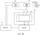
- scaffold 1005 dictates the shape and size of cartridge 1007 which forms a holding frame for scaffold 1005.
- Cartridge 1007 is constructed to grasp portions of scaffold 1005 and hold them in place while cartridge 1007 expands and contracts, effectively stretching and constricting scaffold 1005.
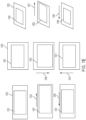
- Scaffold 1005 can be configured with cartridge 1007 to stretch/constrict along any axis appropriate for the tissue being exercised and any orientation that might be relevant, nonlimiting examples of which are shown in FIG. 1A .
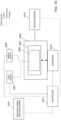
- Rotation means 1012 FIG. 1C
- Rotation can, responding to commands from controller 1011, rotate bioreactor 1009. Rotation can enable cell attachment, with the help of gravity or assisting force.
- the system of the present teachings can be part of a manufacturing line, and thus can be under the control of manufacturing line processor 1014 ( FIG. 1D )
- Controller 1011 communicates the amount and type of media to the media movement means, the type of media is selected, and the media is moved to bioreactor 1009.
- the system can include a drain to either dispose of used media, or recirculate it and possibly condition it for reintroduction into bioreactor 1009.
- the system of the present teachings includes exercise system 1013.
- Exercise system 1013 is physically configured to expand cartridge 1007, which, in turn, stretches scaffold 1005, while remaining in the closed system of the present teachings.
- exercise system 1013 includes magnetic couplings that respond to pressure from a motorized linear actuator that pulls cartridge 1007 to stretch.
- exercise system 1013 includes a braking device that holds cartridge 1007 in a stretched position, when necessary, to complete an exercise plan. The braking device can be automatically or manually activated.
- force sensors are employed during the stretching/exercise of the tissue to measure the resistance/stiffness of the tissue.
- the extent to which the tissue is stretched is limited based on measurements received from the force sensors.
- an exemplary perspective 3-dimensional block diagram view of the system of the present teachings illustrates exemplary cell supply connectors 1017 and media supply connector 1019.
- Exemplary cell supply connectors 1015 are configured to seed cells to both sides of scaffold 1005.
- Connectors such as luer lock connectors can maintain the closed nature of the system of the present teachings.
- scaffold 1005 can be mounted into cartridge 1007, and the combination is further mounted into bioreactor 1009.
- Controller 1011 directs cell supply system 1003 to seed cells onto scaffold 1005, possibly on both sides.
- Controller 1011 directs media supply system 1001 to provide media to bioreactor 1009.
- controller 1011 directs exercise means 1013, which is configured to be sealed from the environment when coupled with cartridge 1007, to stretch cartridge 1007, and therefore scaffold 1005A, as shown in FIG. 3 .
- cartridge 1007 is configured with at least one flexible ring so that when sections of cartridge 1007 expand, spaces 1019 reveal the at least one flexible ring that stretches but retains cartridge part alignment so that cartridge 1007 can return to its original configuration, thus completing an exercise cycle.
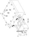
- the bioreactor is configured in two parts, bioreactor top 2005 ( FIG. 5A ) and bioreactor base 2007 ( FIG. 5A ).
- Connectors 2012 FIG. 5A ) secure top 2005 ( FIG. 5A ) to base 2007 ( FIG. 5A ) to protect the contents of the bioreactor from environmental contamination.
- Other configurations are contemplated for the bioreactor of the present teachings.
- the bioreactor can include two side sections that meet and are connected in the middle, or four comer sections that operably couple with one another to form, after connectors are in place, a sealed container.
- the bioreactor can be cylinder-shaped, with top and bottom sections or side sections operably coupled, or other geometric shapes chosen to accommodate specific scaffold and cartridge shapes and sizes, the scaffold and cartridges being housed by the bioreactor. Coupled with the bioreactor, through connected flange 2015, is motorized device case 2001 ( FIG. 5A ) that covers the mechanism that pulls and releases the cartridge within the bioreactor to enable exercise of the tissue on the scaffold in the bioreactor. Seal 2013 ( FIG. 5A ) between flange 2015 ( FIG. 5A ) and the bioreactor serves to seal the contents of the bioreactor from environmental contamination.
- lockout brake 2003 ( FIG. 5A and 5B ), which can retain the cartridge in a desired position.
- lockout brake 2003 ( FIGs. 5A and 5B ) is configured in two parts, for example, but not limited to, lockout brake top 2023 ( FIG. 5B ) and lockout brake bottom 2021 ( FIG. 5B ).
- Thumb screws 2029 ( FIG. 5B ) operably couple lockout brake 2023 ( FIG. 5B ) with lockout brake bottom 2021 ( FIG. 5B ).
- Lockout brake 2003 ( FIGs. 5A and 5B ) is configured to surround motorized device case 2001 ( FIG.
- lockout device 2003 ( FIGs. 5A and 5B ) to enable operable coupling between lockout device 2003 ( FIGs. 5A and 5B ) and the device enclosed in motorized device case 2001 ( FIG. 5A ).
- the coupling is secured by a connector such as, for example, but not limited to, clevis pin 2025 ( FIG. 5B ) fitting into compatible cavity 2006 ( FIG. 5C ) in the mechanism partially enclosed by motorized device case 2001 ( FIG. 5A ).
- lockout device 2003 ( FIGs. 5A and 5B ) is operably coupled with bioreactor 2005 ( FIG. 5A ) by thumb screws 2027 ( FIG. 5B ).
- the present teachings contemplate other configurations such as, for example, an internal lockout mechanism that is controlled remotely.
- This lockout mechanism can include sensors that detect various levels of tissue stretch and provide those data to a controller which can temporarily or permanently disable the device partially enclosed by motorized device case 2001 ( FIG. 5A ) from further exercise.
- the lockout mechanism can engage with the cartridge.
- no lockout mechanism is required because the controller determines the cartridge position and feeds that information to a controller associated with the motorized device, assuring that the tissue exercise regime starts and stops at pre-determined times, or dynamically-determined times, or a combination.
- bioreactor bottom 2007 is configured to provide secure seating for push/pull mechanism 2033 and cartridges 2031.
- a bioreactor with a more expansive footprint than the depicted bioreactor can provide seating for more cartridges 2031 and a larger push/pull mechanism 2033.
- the depicted bioreactor, providing seating for three cartridges 2031 (two cartridges 2031 are depicted) is exemplary only. Further the size and shape of the exercise area is dependent upon the desired type, extent, and direction of tissue exercise. Automatic or manual cell seeding is conducted into the closed bioreactor through luer lock connectors 2009, one for each side of each scaffold 2032 ( FIG.
- multiple seeding ports per scaffold side can be configured, and can provide various cell types to various parts of the scaffold.
- scaffold 2032 FIG. 5D
- a single seeding port can accommodate multiple scaffold surfaces by delivering the same cell type to each surface and/or by delivering different cell types to different scaffold surfaces sequentially.
- push/pull mechanism 2033 is operably coupled with the motorized device, for example, using connectors 2008, and to cartridges 2031 by connectors 2041 ( FIG. 5D ).
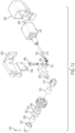
- FIGs. 5E-5G the parts of an exemplary motorized device are shown.
- the motorized device moves push/pull mechanism 2033 ( FIG. 5D ) as discussed herein.
- motorized device case 2001 FIG. 5A
- standoffs 2062 FIG. 5E
- partially encases linear actuator 2065 which couples with motor/magnet coupling 2051 (held in place by pin 2063), magnet/motor coupling 2053, and magnet 2061.
- Flange 2013 and diaphragm 2015 couple the motorized device with bioreactor 2007 ( FIG. 5A ).
- linear actuator 2065 when driven by a motor, urges magnet 2061 ( FIG.
- FIG. 5E through couplings 2051 and 2053, towards opposing magnet 2059 (FIG. 5P), held in place by connector 2058 ( FIG. 5F ).
- Magnet 2059 FIG. 5F
- Magnet coupling 2055 FIG. 5F
- push/pull mechanism 2033 FIG. 5D
- Cartridges 2031 FIG. 5D
- the magnets transmit the positive displacement of the motor to the cartridge and exert a push on cartridges 2031 ( FIG. 5D ), the edges of cartridges 2031 ( FIG.
- a flexible ring connecting the parts of cartridges 2031 ( FIG. 5D ) stretches, and scaffolds 2032 ( FIG. 5D ) stretch.
- the flexible ring may be a band, and O-ring or any other suitable retainer that allows the cartridge to be stretched and return to its original position. The present teachings contemplate other configurations for the movement mechanism.
- servo motors, stepper motors, actuators based on pneumatics or vacuum can replace the linear actuator, and magnets can be replaced, for example, by weights.
- the motor enclosure can be decoupled from the bioreactor base to enable transfer of the bioreactor base from place to place.
- One method for decoupling the motor enclosure from the bioreactor base can include clevis pin 2052 which can release the magnet motor coupling from the motor magnet coupling and enable the attachment of a lockout plate (shown in FIG. 5B ) that can disable further movement of the tissue.
- the bioreactor magnetic coupling can be coupled to the motor enclosure with a diaphragm flange and a bioreactor diaphragm, which together seal contents of the bioreactor from environmental contamination while enabling energy transfer from the motor subsystem to the cartridges.
- Bioreactor base 2007 includes cell seeding output (to the interior of the bioreactor) ports 2073 ( FIG. 5H ) and cell seeding input (from an external (to the bioreactor) cell supply) ports 2081 ( FIG. 5I ) that are used to seed the lower side of the scaffold.
- cell seeding ports 2073 there are as many cell seeding ports 2073 as there are cartridges 2031, but that correspondence is not required. More or fewer cell seeding ports can be configured into bioreactor base 2007 and lid 2005.
- Push/pull mechanism 2033 can rest upon bioreactor base 2007 at bar 2077, and can operably couple with magnet mount 2055 ( FIG.
- Bioreactor base 2007 can include well 2083 into which media is routed from luer lock 2010 ( FIG. 5C ).
- rotation enables seeding from the "top", the side facing away from the gravitational pull of the earth, thus using gravity as an aid to seeding the scaffold.
- the ports on the opposing side of the cartridge 2009 are seeded after rotating the bioreactor so those ports are on top.
- one side is seeded, then, after a pre-selected period of time, the bioreactor is flipped so the unseeded side of the cartridge is facing up, and the scaffold is seeded.
- the scaffold is framed by silicone or another flexible material using a mold.
- the framing results in silicone walls around the perimeter of the scaffold, and these walls retain the seeded cells on top of the scaffold after the seeded cells is deposited. After the cells are exercised and the process is complete, the silicone walls can be cut away.
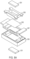
- FIGs. 8A-8D a fixture is shown for generating a second configuration of a cartridge.
- Upper magnet 2501 used with lower magnet 2511, creates compression on decellularized bovine collagen-based matrix (BAM) 2505 ( FIG. 8A ) to inhibit silicone from invading the surface of BAM 2505 ( FIG. 8A ) when it is added to the mold. While magnets are shown to create compression of the molding forms on the BAM, any known technique for generating compression as between the molding forms bay be employed and fall within the scope of this disclosure.
- Scaffold pinch 2503 includes an upper component that is in contact with BAM 2505 ( FIG. 8A ) that inhibits silicone from invading the surface of BAM 2505 ( FIG. 8A ).
- Tray 2507 is used for removing the framed BAM cartridge framed in silicone from the mold after the silicone is fully cured.
- silicone mold 2509 is where the silicone is poured and creates the shape of the framed BAM cartridge.
- silicone mold 2509 includes table top 2512 ( FIG. 8A ) which is the lower surface of SILICONE mold 2509 that is in contact with the lower side of BAM 2505 ( FIG. 8A ) to inhibit the SILICONE from invading the lower surface.
- Outer edge 2510 ( FIG. 8B ) is a clarification of the lines in the drawing between tray 2507 and SILICONE mold 2509.
- Cartridge 2031 is an example of a frame that enables the mechanical exercise of scaffold 2207.
- cartridge 2031 is configured to grip scaffold 2207, the edges of which are captured between frame parts 2201/2211 and 2203/2213.
- the scaffold is not framed by SILICONE. Instead, the scaffold frame and o-rings 2255/2209 seal the perimeter of the scaffold.
- frame parts 2201 and 2211 are operably coupled by fasteners 2225.
- frame parts 2203 and 2213 are also operably coupled.
- frame parts 2201/2211 and frame parts 2203/2213 separate 2221/2223 at seams 2222/2224 ( Fig. 6B ) when cartridge 2031 is expanded, as described herein.
- scaffold 2207 which is gripped between frame parts, is expanded.
- seam 2221/2223 is closed, o-rings 2255/2209 and the frames create walls around the scaffold, resulting in a well into which the seeding media can be injected and the cells are forced to settle on the scaffold contained in the desired scaffold seeding area.
- exercise starts and the cartridge is fully surrounded by media. Since the cells are now fixed to the scaffold, opening the seams of the cartridge does not provide an opening for the cells to flow away from the scaffold.
- exercise of scaffold 2207 can include movement in at least two directions, thus, the expansion is followed by a contraction in which frame parts 2201/2211 and 2203/2213 return to a resting position in which the space at seams 2221/2223 is closed.
- Cartridge 2031 and scaffold 2207 can undergo further expansions and contractions when required for tissue maturation.
- the present teachings contemplate various shapes and sizes of scaffolds and their associated cartridges.
- a scaffold can take virtually any two-dimensional geometric shape for which a complementary cartridge can be constructed.
- a circular scaffold can be surrounded by a circular cartridge that can be stretched in various directions, not limited to two directions, depending upon the location(s) of seams between the sections of the cartridge.
- the bioreactor can take a general shape that accommodates both two- and three-dimensional scaffolds, or can take a specific shape depending upon the shape of the scaffold.
- cartridge 2031 includes flexible material coupling frame part 2201 with frame part 2203, and frame part 2211 with frame part 2213.
- flexible ring 2255 can rest in a first channel (not shown), and flexible ring 2209 can rest in channel 2217.
- the flexible rings which can provide sealing as well as stretching, can be constructed of material chosen based on operating temperature, operating pressure, finish, and stretch.
- Such materials can include, but are not limited to including, nitrile, fluoroelastomer, silicone, highly saturated nitrile, and PTFE, among others.
- the effect of friction due to intermittent movement (breakout friction) and continuous movement (running friction) can cause high pressures and heat, respectively, to build up.
- breakout friction breakout friction
- running friction continuous movement
- the size, squeeze, stretch, chemical compatibility, temperature, pressure, and friction of the application are considered in material selection for the flexible rings.
- the system of the present teachings can accommodate various designs, materials, and construction of the cartridge and flexible ring combination.
- the second implementation includes a motor subsystem that drives the motion of cartridges inside a bioreactor, and a mechanism for rotating the bioreactor.
- the motor subsystem can be decoupled from the bioreactor, and cell seeding is accomplished through seed ports integrated with the cartridges.
- An example of the second implementation is system 2300 which includes, but is not limited to including, a rotary yoke 2303 to rotate the bioreactor, and a detachable motor subsystem.
- the motor subsystem can drive the movement of cartridges 2363 enclosed in the bioreactor subsystem.
- cartridge 2363 includes frame parts connected by a flexible ring. The frame parts hold the scaffold between them, and split to enable exercise of the scaffold.
- the motor subsystem includes a magnetic coupling to enable movement of the frame and the scaffold.
- magnet tube 2357 encloses first magnet 2355.
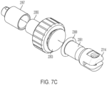
- Cooperating magnet 2351 is positioned across diaphragm 2353 from first magnet 2355, and o-ring 2399 ( FIG. 7C ) and diaphragm 2353 can seal the bioreactor from environmental contaminants.
- O-ring 2399 FIG. 7B
- leak protection can be provided by a material such as polytetrafluroethylene, nitrile, neoprene, ethylene propylene diene monomer rubber, and fluorocarbon.
- o-ring 2399 can be constructed of, for example, a co-polymer of ethylene, tetrafluoroethylene, and perfluoromethylvinyl ether.
- Cells can be provided directly to the scaffolds in cartridges 2363 through fluid connector 2373 ( FIG. 7B ), the cells entering the cartridge well through fluid connector 2373.
- One seeding fluid connector 2373 can seed a first surface of the scaffold, while the other seeding fluid connector 2373 can seed a second surface of the scaffold, since the scaffold is located between the two ports that connect to the fluid connectors ( FIG. 7M ).
- Fluid connectors 2375 can simultaneously admit media and nutrients to the bioreactor chamber and vent the chamber to remove air from the chamber.
- magnet cup 2314 is coupled to the motor subsystem by connector 2316 which connects magnet cup 2314 with linkage 2311 in a prismatic-like joint.
- connector 2316 By removing connector 2316, the motor subsystem can be decoupled from the bioreactor subsystem.
- the position of pull mechanism 2369 ( FIG. 7A ) is retained as described herein, and the bioreactor subsystem can be transported to where the tissue exercised on cartridges 2363 ( FIG. 7A ) is needed. Likewise, the tissue can be further exercised by reconnecting the motor subsystem with the bioreactor subsystem.
- Other forms of connection between the bioreactor subsystem and the motor subsystem are contemplated by the present teachings.
- linkage 2311 and magnet cup 2314 can be constructed as a click-to-connect coupling.
- connector 2316 can include a pin or a screw.
- Magnet cup 2314 and linkage 2311 can be the two parts of a ball joint or a knuckle joint.
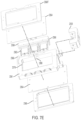
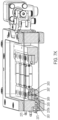
- FIG. 7E the parts of the bioreactor subsystem are shown.
- the various parts of the bioreactor subsystem are held together by frame clamps 2368T and 2368.
- films 2364 Resting on one side of each frame clamp are films 2364 which surround and protect cartridges 2363 and the scaffolds they exercise. In some configurations, films 2364 are gas permeable, making it unnecessary to provide a sterile filter to add gas to the environment of cartridges 2363.
- Cartridges 2363 are mounted to pull mechanism 2369. Coupled with pull mechanism 2369 are rails 2366 which slide into the guiderail mount within guiderail 2378, which is cut into base 2361.
- motor linkage 2405 is activated to move pull mechanism 2403 from its resting position shown in FIG. 7F-1 to its extended position shown in FIG. 7F-2 by sliding rails within guardrail 2378 ( FIG. 7E ).
- Cartridge seam 2409 forms gap 2411 when pull mechanism 2403 is moved to its extended position, pulling first cartridge part 2407 away from second cartridge part 2415 and exercising the scaffold held within the cartridge.
- Cartridge part 2415 is fixed to base 2413, whereas cartridge part 2407 is freemto slide in guardrail 2378.
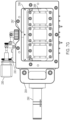
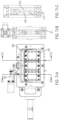
- FIGs. 7G-7J an implementation of the movement means of the present teachings is described.
- Protruding from the side of the bioreactor system is a first part of the movement means.
- the first part interfaces directly with pull mechanism 2369 ( FIG. 7G ) at the bioreactor end, and with the motor subsystem at the opposing end.
- the interface with pull mechanism 2369 ( FIG. 7G ) includes magnet tube 2357 held in place with slotted spring pin 2367 ( FIG. 7H ).
- the present teachings contemplate other connection means.
- Magnet 2355 and 2351 FIG. 7J ), when coupled, supply pressure to pull mechanism 2369 ( FIG. 7G ) to pull the cartridges apart at their seams 2409 ( FIG. 7G ) and exercise the scaffolds.
- Magnet 2351 couples directly to magnet 2351, causing magnet 2351 to move.
- Magnet 2351 is directly coupled to pull mechanism 2369 by way of magnet 2355.
- the magnetic force between magnets 2351 and 2355 results in a movement of magnet 2355 when magnet 2351 moves.
- Magnet cup 2314 houses magnet 2351 and provides half of the linkage between the bioreactor interface parts and the motor subsystem.
- Magnet cup 2314 and linkage structure 2311 form a rotatable connection at tongue 2492 that slides into a gap in magnet cup 2314. The geometry of the gap enables linkage structure 2311 to rotate to move the motor subsystem to the side of the bioreactor.
- the motor structure When the motor structure is needed to exercise the scaffold, it can be rotated to face the bioreactor so that the linear actuator can exert pressure on the interface structure and therefore on pull mechanism 2369 ( FIG. 7G ).
- the motor pressure moves the cartridges into a contracted position to complete the exercise cycle begun by the magnetic force.
- linear actuator 2307 supplies pressure through plunger 2310.
- Plunger 2310 relies on washer 2354/stacked wave disc spring 2352, mounted onto linkage 2311 through shoulder screw 2398, to provide the pressure onto pull mechanism 2369 ( FIG. 7G ), buffered by spring 2352.
- Shaft mount 2303 securely couples linear actuator 2307 with linkage 2311.
- Position sensor mounting brick 2499 provides a mounting option for a position sensor to track the location of plunger 2310, the data from which can be used to control the scaffold exercise regime.
- Power and environmental protection for linear actuator 2307 can be provided by junction box 2305, capped by junction box cap 2395.
- the rotary shaft mount 2304 ( FIG. 7G ) provides a means for rotary activation means 2360 to fully rotate the bioreactor in order to seed cells on both sides of the scaffold.
- cell seeding port 2413 interfaces directly with cartridge 2301.
- Media to fill the bioreactor cavity is provided through media port 2411.
- Cells are seeded onto one side of the scaffold, and allowed to settle onto the scaffold and attach.
- the rotary actuator flips the bioreactor, so the opposite side of the scaffold can be seeded with cells, which are allowed to settle and attach.
- the exercise/stretch routine starts after both sides are seeded and the cells have attached.
- FIGs. 7K-7M the components of the configuration that enable multi-surface cell seeding are shown. Specifically, referring to FIG. 7K , seeding of a first surface begins at fluid inlet 2373.
- the bioreactor interior is sealed from the environment beginning at seal 2601.
- the direction of travel of the cells introduced through inlet 2373 is shown by the arrows beginning at inlet 2373.
- the cells are directed to exit out ports 2612 and 2614 ( FIG. 7M ) and deposit above where the scaffold would be (scaffold not depicted in FIG. 7K ). Seals 2609 and 2607 also provide barriers from environmental contamination that could be introduced by inlet 2373. Also shown are media/vent inlet/outlet 2375.
- the media and/or nutrients that are introduced into the well of the bioreactor enter the bioreactor through cavity 2375 and exit into the internal region 2375A surrounding the bioreactors ( FIG. 7K ).
- the seeded cells are trapped on scaffold 2605 by a flexible ring described elsewhere herein that rests in cavity 2603.
- Detail B ( FIG. 7M ) of section A-A ( FIG. 7L ) are cross-sections that show the details of FIG. 7K . Seeding a second side of scaffold 2605 is shown in detail D ( FIG. 7M ) of section C-C ( FIG. 7L ).
- Cells entering inlet 2373A travel on the path shown by the arrows in section C-C, and seals 2602 and 2611 prevents environmental contamination from inlet 2373A.
- the cells in this case do not cross scaffold 2605. Instead the cells are deposited on scaffold 2605 on the same side of scaffold 2605 on which the cells entered, at outlet 2612 ( FIG. 7M ). Section C-C and detail D show components that would be rotated 180° before the cells are deposited in order to take advantage of gravity to encourage the cells to attach.
- one of the systems of the present teachings was placed at 37°C, 5% CO 2 .
- C2C12 cells were fluidically seeded within the sealed bioreactor onto both sides of the scaffolds through the designated seeding ports of the sealed bioreactor or, possibly, directly into the cartridge.
- a first scaffold side was seeded, then a pre-selected amount of time elapsed before the second side was seeded.
- the bioreactor was fully closed to the environment throughout the seeding process, which allowed the seeding to be performed in a non-cleanroom environment, but using an aseptic technique and specific sample ports, with no contamination issue.
- a cell harvest solution was quenched with an equal volume of proliferation media, and cells were counted, centrifuged, and resuspended at a desired concentration for seeding.
- An amount of cell solution was added to a sterile syringe to seed each scaffold with a pre-selected number of cells.
- the syringe was connected to the Side B seeding ports above each cartridge position, and the seeding charge was manually delivered.
- a syringe filled with sterile air was then attached to each seeding port to chase out the remaining seeding charge volume.
- Side B was seeded first so that Side A was already in the upward-facing position when exercise is started. After 24 hours, the bioreactor was flipped so Side A was facing upward, ensuring that the headspace air gap and any separate bubbles fully translated from Side B. The cell harvest and seeding procedure was repeated to seed side A.
- the bioreactors were drained 24 hours after the second seeding.
- the reactors were refilled with differentiation media, and an exercise protocol was initiated.
- the bioreactor configuration used for the tests is easy to assemble, incorporates a leakproof cartridge and hermetically sealed reservoir, and has a robust exercise mechanism which can apply up to 25% strain.
- the bioreactor demonstrates an effective method for fully enclosed, hydrogel-free delivery of cells to BAM scaffolds resulting in even cellular distribution and high cell coverage.
- the reservoir also allows for an ⁇ 60% reduction in required media volume compared to other similar bioreactors.
- the cartridge and bioreactor concepts are amenable to cost-effective production and scale-up.
- a method for use of one of the configurations of the system of the present teachings was tested using the following steps: (1) wash all components of the bioreactor with soap and water, rinse with DI and allow to dry; (2) autoclave all components (excluding BAM scaffolds) for 30 minutes at 121°C; (3) rehydrate sterilized BAM scaffolds by covering in sterile PBS for at least 10 minutes; (4) drape the BAM over the bottom cartridge piece such that the BAM covers all of the O-ring but not the seeding ports, cover with top cartridge and seal top and bottom pieces together; (5) trim excess BAM from the edges of the cartridge and store assembled cartridge in sterile PBS to prevent dehydration during subsequent cartridge assembly; (6) load the cartridges into the bioreactor; (7) flip the bioreactor to apply the bottom-side silicone membrane and stainless steel plate, then flip again to apply the topside silicone membrane and stainless steel plate; (8) fill the bioreactor with 60 ml of growth media through the fill/drain port system, and remove any air from the bioreactor by tiling the
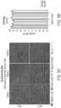
- FIG. 9A is a pictorial illustration of the result of static seeding followed by five days of exercise.
- actin is shown in red, the nuclei are shown in blue.
- FIGs. 9B and 9C are graphical illustrations of the results.
- side A and side B coverages were measured to be approximately 96% on average, with sides A and B topping out at over 97% in the first and second positions, respectively.
- FIG. 9C it can be seen that the primary actin angle of alignment was within 5° for all cartridges/sides, and coherency of the actin alignment was consistently high (combined sides ⁇ 0.70).
Landscapes
- Health & Medical Sciences (AREA)
- Engineering & Computer Science (AREA)
- Life Sciences & Earth Sciences (AREA)
- Chemical & Material Sciences (AREA)
- Organic Chemistry (AREA)
- Bioinformatics & Cheminformatics (AREA)
- Wood Science & Technology (AREA)
- Zoology (AREA)
- Genetics & Genomics (AREA)
- Biomedical Technology (AREA)
- Biotechnology (AREA)
- Biochemistry (AREA)
- General Engineering & Computer Science (AREA)
- General Health & Medical Sciences (AREA)
- Microbiology (AREA)
- Sustainable Development (AREA)
- Clinical Laboratory Science (AREA)
- Cell Biology (AREA)
- Molecular Biology (AREA)
- Immunology (AREA)
- Analytical Chemistry (AREA)
- Rheumatology (AREA)
- Mechanical Engineering (AREA)
- Computer Hardware Design (AREA)
- Apparatus Associated With Microorganisms And Enzymes (AREA)
- Micro-Organisms Or Cultivation Processes Thereof (AREA)
- Immobilizing And Processing Of Enzymes And Microorganisms (AREA)
Applications Claiming Priority (3)
| Application Number | Priority Date | Filing Date | Title |
|---|---|---|---|
| US202263268940P | 2022-03-07 | 2022-03-07 | |
| EP23713563.7A EP4490263A1 (de) | 2022-03-07 | 2023-03-07 | Gewebereifungsbioreaktorsysteme mit gleichmässiger zellverteilung |
| PCT/US2023/063816 WO2023172887A1 (en) | 2022-03-07 | 2023-03-07 | Tissue maturation bioreactor systems with uniform cell distribution |
Related Parent Applications (1)
| Application Number | Title | Priority Date | Filing Date |
|---|---|---|---|
| EP23713563.7A Division EP4490263A1 (de) | 2022-03-07 | 2023-03-07 | Gewebereifungsbioreaktorsysteme mit gleichmässiger zellverteilung |
Publications (2)
| Publication Number | Publication Date |
|---|---|
| EP4574967A2 true EP4574967A2 (de) | 2025-06-25 |
| EP4574967A3 EP4574967A3 (de) | 2025-10-08 |
Family
ID=85772794
Family Applications (3)
| Application Number | Title | Priority Date | Filing Date |
|---|---|---|---|
| EP25173676.5A Pending EP4574968A3 (de) | 2022-03-07 | 2023-03-07 | Gewebereifungsbioreaktorsysteme mit gleichmässiger zellverteilung |
| EP25173675.7A Pending EP4574967A3 (de) | 2022-03-07 | 2023-03-07 | Gewebereifungsbioreaktorsysteme mit gleichmässiger zellverteilung |
| EP23713563.7A Pending EP4490263A1 (de) | 2022-03-07 | 2023-03-07 | Gewebereifungsbioreaktorsysteme mit gleichmässiger zellverteilung |
Family Applications Before (1)
| Application Number | Title | Priority Date | Filing Date |
|---|---|---|---|
| EP25173676.5A Pending EP4574968A3 (de) | 2022-03-07 | 2023-03-07 | Gewebereifungsbioreaktorsysteme mit gleichmässiger zellverteilung |
Family Applications After (1)
| Application Number | Title | Priority Date | Filing Date |
|---|---|---|---|
| EP23713563.7A Pending EP4490263A1 (de) | 2022-03-07 | 2023-03-07 | Gewebereifungsbioreaktorsysteme mit gleichmässiger zellverteilung |
Country Status (6)
| Country | Link |
|---|---|
| US (1) | US12553016B2 (de) |
| EP (3) | EP4574968A3 (de) |
| JP (1) | JP2025508130A (de) |
| CA (1) | CA3245578A1 (de) |
| IL (1) | IL315489A (de) |
| WO (1) | WO2023172887A1 (de) |
Families Citing this family (1)
| Publication number | Priority date | Publication date | Assignee | Title |
|---|---|---|---|---|
| DE102024200470A1 (de) * | 2024-01-18 | 2025-07-24 | 2Mag Ag | Konditionierungskammer für eine Konditionierung von Gewebezellen |
Citations (4)
| Publication number | Priority date | Publication date | Assignee | Title |
|---|---|---|---|---|
| WO2007052653A1 (ja) | 2005-10-31 | 2007-05-10 | Strex Incorporation | 培養容器および培養装置 |
| JP2008263986A (ja) | 2000-12-22 | 2008-11-06 | Keele Univ | 磁気的に発生させた機械的応力を使用して組織を培養する方法 |
| US20210139859A1 (en) | 2013-08-22 | 2021-05-13 | University Of Pittsburgh - Of The Commonwealth System Of Higher Education | Modular, microfluidic, mechanically active bioreactor for 3d, multi-tissue, tissue culture |
| WO2022010594A1 (en) | 2020-07-09 | 2022-01-13 | University Of Virginia Patent Foundation | Hermetically or aseptically sealed bioreactor system and related method thereof |
Family Cites Families (4)
| Publication number | Priority date | Publication date | Assignee | Title |
|---|---|---|---|---|
| US7229820B2 (en) * | 2002-06-13 | 2007-06-12 | Wilson Wolf Manufacturing Corporation | Apparatus and method for culturing and preserving tissue constructs |
| ES2733318T3 (es) * | 2004-05-06 | 2019-11-28 | Univ Hospital Of Basel | Biorreactor para ingeniería de tejidos |
| US9206383B2 (en) * | 2009-12-07 | 2015-12-08 | The Trustees Of Columbia University In The City Of New York | Bioreactor, devices, systems and methods |
| EP3176252A1 (de) * | 2015-12-04 | 2017-06-07 | Ludwig-Maximilians-Universität München | System und verfahren zur bestimmung einer kraft, die auf eine zell- oder gewebekultur angewendet oder dadurch erzeugt wird |
-
2023
- 2023-03-07 WO PCT/US2023/063816 patent/WO2023172887A1/en not_active Ceased
- 2023-03-07 EP EP25173676.5A patent/EP4574968A3/de active Pending
- 2023-03-07 IL IL315489A patent/IL315489A/en unknown
- 2023-03-07 EP EP25173675.7A patent/EP4574967A3/de active Pending
- 2023-03-07 EP EP23713563.7A patent/EP4490263A1/de active Pending
- 2023-03-07 US US18/179,477 patent/US12553016B2/en active Active
- 2023-03-07 JP JP2024553798A patent/JP2025508130A/ja active Pending
- 2023-03-07 CA CA3245578A patent/CA3245578A1/en active Pending
Patent Citations (4)
| Publication number | Priority date | Publication date | Assignee | Title |
|---|---|---|---|---|
| JP2008263986A (ja) | 2000-12-22 | 2008-11-06 | Keele Univ | 磁気的に発生させた機械的応力を使用して組織を培養する方法 |
| WO2007052653A1 (ja) | 2005-10-31 | 2007-05-10 | Strex Incorporation | 培養容器および培養装置 |
| US20210139859A1 (en) | 2013-08-22 | 2021-05-13 | University Of Pittsburgh - Of The Commonwealth System Of Higher Education | Modular, microfluidic, mechanically active bioreactor for 3d, multi-tissue, tissue culture |
| WO2022010594A1 (en) | 2020-07-09 | 2022-01-13 | University Of Virginia Patent Foundation | Hermetically or aseptically sealed bioreactor system and related method thereof |
Non-Patent Citations (4)
| Title |
|---|
| CLEMONS ET AL.: "Coherency image analysis to quantify collagen architecture: implications in scar assessment", RSC ADVY., vol. 8, 2018, pages 9661 |
| CORONA ET AL.: "Further Development of a Tissue Engineered Muscle Repair Construct Jn Vitro for Enhanced Functional Recovery Following Implantation Jn Vivo in a Murine Model of Volumetric Muscle Loss Injury", TISSUE ENGINEERING: PART A, vol. 18, 2012, pages 11 - 12 |
| CORONA ET AL.: "Implantation of Jn Vitro Tissue Engineering Muscle Repair Constructs and Bladder Acellular Matrices Partially Restore Jn Vivo Skeletal Muscle Function in a Rat Model of Volumetric Muscle Loss Injury", TISSUE ENGINEERING: PART A, vol. 20, 2014, pages 3 - 4 |
| MACHINGAL ET AL.: "A Tissue-Engineered Muscle Repair Construct for Functional Restoration of an Irrecoverable Muscle Injury in a Murine Model", TISSUE ENGINEERING: PART A, vol. 17, 2011, pages 17 - 18 |
Also Published As
| Publication number | Publication date |
|---|---|
| EP4574967A3 (de) | 2025-10-08 |
| WO2023172887A1 (en) | 2023-09-14 |
| IL315489A (en) | 2024-11-01 |
| US20230279322A1 (en) | 2023-09-07 |
| JP2025508130A (ja) | 2025-03-21 |
| US12553016B2 (en) | 2026-02-17 |
| EP4574968A2 (de) | 2025-06-25 |
| EP4574968A3 (de) | 2025-10-22 |
| CA3245578A1 (en) | 2023-09-14 |
| EP4490263A1 (de) | 2025-01-15 |
Similar Documents
| Publication | Publication Date | Title |
|---|---|---|
| US6432713B2 (en) | Method and apparatus for cultivating a cell or tissue | |
| EP1882030B1 (de) | Vorrichtung zur bereitstellung von medien an zellkulturmodule | |
| US11773364B2 (en) | Automated cell culturing and harvesting device | |
| JP4104822B2 (ja) | 3次元組織構築物の接種および培養時にinvivo条件をシミュレートするための装置および方法 | |
| US7906323B2 (en) | Automated bioculture and bioculture experiments system | |
| KR20080087003A (ko) | 세포 배양 방법 및 그 방법을 이용한 자동 배양 장치 | |
| EP4574967A2 (de) | Gewebereifungsbioreaktorsysteme mit gleichmässiger zellverteilung | |
| JP4607432B2 (ja) | 細胞又は組織の培養装置 | |
| US20080032278A1 (en) | Engineered Tubular Tissue Structures | |
| CN111893040B (zh) | 一种具有在线操作功能的力学模态可调旋转生物培养器 | |
| US20250092346A1 (en) | Tissue culture vessel for preparation of compressed hydrogel skin grafts and related methods and systems | |
| GB2617629A (en) | System for cell culture | |
| US12116562B1 (en) | Integrated system for the automated passaging of anchorage dependent cell cultures | |
| KR20180003876A (ko) | 탈세포화된 조직용 관류 생물반응기 시스템과, 이를 이용한 기관의 유지 및 세포 접종 방법 | |
| EP4482943A1 (de) | Bioreaktoranordnungen, perfusionsbioreaktorsysteme und verfahren |
Legal Events
| Date | Code | Title | Description |
|---|---|---|---|
| PUAI | Public reference made under article 153(3) epc to a published international application that has entered the european phase |
Free format text: ORIGINAL CODE: 0009012 |
|
| STAA | Information on the status of an ep patent application or granted ep patent |
Free format text: STATUS: THE APPLICATION HAS BEEN PUBLISHED |
|
| AC | Divisional application: reference to earlier application |
Ref document number: 4490263 Country of ref document: EP Kind code of ref document: P |
|
| AK | Designated contracting states |
Kind code of ref document: A2 Designated state(s): AL AT BE BG CH CY CZ DE DK EE ES FI FR GB GR HR HU IE IS IT LI LT LU LV MC ME MK MT NL NO PL PT RO RS SE SI SK SM TR |
|
| REG | Reference to a national code |
Ref country code: DE Ref legal event code: R079 Free format text: PREVIOUS MAIN CLASS: C12N0005077000 Ipc: C12M0003000000 |
|
| PUAL | Search report despatched |
Free format text: ORIGINAL CODE: 0009013 |
|
| AK | Designated contracting states |
Kind code of ref document: A3 Designated state(s): AL AT BE BG CH CY CZ DE DK EE ES FI FR GB GR HR HU IE IS IT LI LT LU LV MC ME MK MT NL NO PL PT RO RS SE SI SK SM TR |
|
| RIC1 | Information provided on ipc code assigned before grant |
Ipc: C12M 3/00 20060101AFI20250903BHEP Ipc: C12M 1/00 20060101ALI20250903BHEP Ipc: C12M 1/12 20060101ALI20250903BHEP Ipc: C12M 1/42 20060101ALI20250903BHEP Ipc: C12M 1/36 20060101ALI20250903BHEP Ipc: C12N 5/00 20060101ALI20250903BHEP Ipc: C12N 5/077 20100101ALI20250903BHEP |
|
| STAA | Information on the status of an ep patent application or granted ep patent |
Free format text: STATUS: REQUEST FOR EXAMINATION WAS MADE |