EP4574691A1 - Packer machine and wrapping method to produce a pack for smoking articles - Google Patents
Packer machine and wrapping method to produce a pack for smoking articles Download PDFInfo
- Publication number
- EP4574691A1 EP4574691A1 EP24219382.9A EP24219382A EP4574691A1 EP 4574691 A1 EP4574691 A1 EP 4574691A1 EP 24219382 A EP24219382 A EP 24219382A EP 4574691 A1 EP4574691 A1 EP 4574691A1
- Authority
- EP
- European Patent Office
- Prior art keywords
- wrapping
- conveyor
- path
- folding
- group
- Prior art date
- Legal status (The legal status is an assumption and is not a legal conclusion. Google has not performed a legal analysis and makes no representation as to the accuracy of the status listed.)
- Pending
Links
Images




Classifications
-
- B—PERFORMING OPERATIONS; TRANSPORTING
- B65—CONVEYING; PACKING; STORING; HANDLING THIN OR FILAMENTARY MATERIAL
- B65B—MACHINES, APPARATUS OR DEVICES FOR, OR METHODS OF, PACKAGING ARTICLES OR MATERIALS; UNPACKING
- B65B19/00—Packaging rod-shaped or tubular articles susceptible to damage by abrasion or pressure, e.g. cigarettes, cigars, macaroni, spaghetti, drinking straws or welding electrodes
- B65B19/02—Packaging cigarettes
- B65B19/22—Wrapping the cigarettes; Packaging the cigarettes in containers formed by folding wrapping material around formers
- B65B19/223—Wrapping the cigarettes; Packaging the cigarettes in containers formed by folding wrapping material around formers in a curved path; in a combination of straight and curved paths, e.g. on rotary tables or other endless conveyors
-
- B—PERFORMING OPERATIONS; TRANSPORTING
- B65—CONVEYING; PACKING; STORING; HANDLING THIN OR FILAMENTARY MATERIAL
- B65B—MACHINES, APPARATUS OR DEVICES FOR, OR METHODS OF, PACKAGING ARTICLES OR MATERIALS; UNPACKING
- B65B19/00—Packaging rod-shaped or tubular articles susceptible to damage by abrasion or pressure, e.g. cigarettes, cigars, macaroni, spaghetti, drinking straws or welding electrodes
- B65B19/02—Packaging cigarettes
- B65B19/025—Packaging cigarettes in webs of flexible sheet material
-
- B—PERFORMING OPERATIONS; TRANSPORTING
- B65—CONVEYING; PACKING; STORING; HANDLING THIN OR FILAMENTARY MATERIAL
- B65B—MACHINES, APPARATUS OR DEVICES FOR, OR METHODS OF, PACKAGING ARTICLES OR MATERIALS; UNPACKING
- B65B19/00—Packaging rod-shaped or tubular articles susceptible to damage by abrasion or pressure, e.g. cigarettes, cigars, macaroni, spaghetti, drinking straws or welding electrodes
- B65B19/02—Packaging cigarettes
- B65B19/22—Wrapping the cigarettes; Packaging the cigarettes in containers formed by folding wrapping material around formers
- B65B19/24—Wrapping the cigarettes; Packaging the cigarettes in containers formed by folding wrapping material around formers using hollow mandrels through which groups of cigarettes are fed
-
- B—PERFORMING OPERATIONS; TRANSPORTING
- B65—CONVEYING; PACKING; STORING; HANDLING THIN OR FILAMENTARY MATERIAL
- B65B—MACHINES, APPARATUS OR DEVICES FOR, OR METHODS OF, PACKAGING ARTICLES OR MATERIALS; UNPACKING
- B65B35/00—Supplying, feeding, arranging or orientating articles to be packaged
- B65B35/30—Arranging and feeding articles in groups
- B65B35/44—Arranging and feeding articles in groups by endless belts or chains
-
- B—PERFORMING OPERATIONS; TRANSPORTING
- B65—CONVEYING; PACKING; STORING; HANDLING THIN OR FILAMENTARY MATERIAL
- B65B—MACHINES, APPARATUS OR DEVICES FOR, OR METHODS OF, PACKAGING ARTICLES OR MATERIALS; UNPACKING
- B65B49/00—Devices for folding or bending wrappers around contents
- B65B49/02—Fixed or resiliently-mounted folders, e.g. non-driven rollers
- B65B49/04—Ploughs or plates with inclined slots or opposed inclined edges
-
- B—PERFORMING OPERATIONS; TRANSPORTING
- B65—CONVEYING; PACKING; STORING; HANDLING THIN OR FILAMENTARY MATERIAL
- B65B—MACHINES, APPARATUS OR DEVICES FOR, OR METHODS OF, PACKAGING ARTICLES OR MATERIALS; UNPACKING
- B65B49/00—Devices for folding or bending wrappers around contents
- B65B49/08—Reciprocating or oscillating folders
-
- B—PERFORMING OPERATIONS; TRANSPORTING
- B65—CONVEYING; PACKING; STORING; HANDLING THIN OR FILAMENTARY MATERIAL
- B65B—MACHINES, APPARATUS OR DEVICES FOR, OR METHODS OF, PACKAGING ARTICLES OR MATERIALS; UNPACKING
- B65B59/00—Arrangements to enable machines to handle articles of different sizes, to produce packages of different sizes, to vary the contents of packages, to handle different types of packaging material, or to give access for cleaning or maintenance purposes
- B65B59/001—Arrangements to enable adjustments related to the product to be packaged
-
- B—PERFORMING OPERATIONS; TRANSPORTING
- B65—CONVEYING; PACKING; STORING; HANDLING THIN OR FILAMENTARY MATERIAL
- B65B—MACHINES, APPARATUS OR DEVICES FOR, OR METHODS OF, PACKAGING ARTICLES OR MATERIALS; UNPACKING
- B65B59/00—Arrangements to enable machines to handle articles of different sizes, to produce packages of different sizes, to vary the contents of packages, to handle different types of packaging material, or to give access for cleaning or maintenance purposes
- B65B59/005—Adjustable conveying means
-
- B—PERFORMING OPERATIONS; TRANSPORTING
- B65—CONVEYING; PACKING; STORING; HANDLING THIN OR FILAMENTARY MATERIAL
- B65B—MACHINES, APPARATUS OR DEVICES FOR, OR METHODS OF, PACKAGING ARTICLES OR MATERIALS; UNPACKING
- B65B59/00—Arrangements to enable machines to handle articles of different sizes, to produce packages of different sizes, to vary the contents of packages, to handle different types of packaging material, or to give access for cleaning or maintenance purposes
- B65B59/04—Machines constructed with readily-detachable units or assemblies, e.g. to facilitate maintenance
-
- B—PERFORMING OPERATIONS; TRANSPORTING
- B65—CONVEYING; PACKING; STORING; HANDLING THIN OR FILAMENTARY MATERIAL
- B65B—MACHINES, APPARATUS OR DEVICES FOR, OR METHODS OF, PACKAGING ARTICLES OR MATERIALS; UNPACKING
- B65B65/00—Details peculiar to packaging machines and not otherwise provided for; Arrangements of such details
- B65B65/003—Packaging lines, e.g. general layout
-
- B—PERFORMING OPERATIONS; TRANSPORTING
- B65—CONVEYING; PACKING; STORING; HANDLING THIN OR FILAMENTARY MATERIAL
- B65B—MACHINES, APPARATUS OR DEVICES FOR, OR METHODS OF, PACKAGING ARTICLES OR MATERIALS; UNPACKING
- B65B65/00—Details peculiar to packaging machines and not otherwise provided for; Arrangements of such details
- B65B65/003—Packaging lines, e.g. general layout
- B65B65/006—Multiple parallel packaging lines
-
- B—PERFORMING OPERATIONS; TRANSPORTING
- B65—CONVEYING; PACKING; STORING; HANDLING THIN OR FILAMENTARY MATERIAL
- B65B—MACHINES, APPARATUS OR DEVICES FOR, OR METHODS OF, PACKAGING ARTICLES OR MATERIALS; UNPACKING
- B65B2230/00—Aspects of the final package
- B65B2230/04—Cigarette packages having a hinged lid
Definitions
- the present invention relates to a packer machine and to a wrapping method to produce a pack for smoking articles.
- the present invention is advantageously applied to the manufacturing of a rigid pack for cigarettes with a hinged lid, to which the following discussion will explicitly refer without thereby losing generality;
- the rigid pack for cigarettes can be either of single type (traditional) and thus containing one single wrap or can be of "twin" type and thus containing two wraps next to each other, in particular twin wraps.
- Rigid packs for cigarettes with a hinged lid are the most widespread packs for cigarettes currently on the market since they are simple to manufacture, easy and practical to use, and offer good protection to the cigarettes contained on their inside.
- a rigid pack for cigarettes with a hinged lid comprises a wrap consisting of a group of cigarettes wrapped in a wrapping sheet and a rigid outer casing which houses the wrap on its inside.
- the outer casing consists of a cup-shaped container, which houses the wrap and has an open upper end, and a lid, which is also cup-shaped and is hinged to the container so as to rotate, with respect to the container, between an open position and a closed position of the open end.
- Patent applications EP4079648A1 , EP4051595A1 , EP4043350A1 and EP3725690A1 describe a packer machine for producing a rigid pack for cigarettes having a (at least one) wrap obtained by folding a wrapping sheet made of metallic paper around a group of cigarettes and an outer container obtained by folding a blank and a collar around the wrap.
- the folding of the wrapping sheet around the group of cigarettes is completed at the end of the straight and horizontal first wrapping path in a shuttle that transfers the group of cigarettes wrapped by the wrapping sheet from the wrapping conveyor to the transport conveyor: in fact, in order to be able to complete the folding of the wrapping sheet around the group of cigarettes, it is necessary to separate the group of cigarettes wrapped by the wrapping sheet from a pushing element of the wrapping conveyor so as to free the rear wall of the group of cigarettes engaged by the pushing element.
- the shuttle must be capable of holding the group of cigarettes guaranteeing high precision in the positioning of the group of cigarettes (a prerequisite condition in order to be able to perform quality folds when the folding of the wrapping sheet around the group of cigarettes is completed) without anyway compressing the group of cigarettes too much (so as not to cause undesired permanent deformations); namely, the shuttle must be capable of transporting the group of cigarettes without damaging the group of cigarettes due to an excessive compression of the group of cigarettes and, at the same time, without leaving the group of cigarettes excessively free so as to avoid an undesired uncontrolled loss of shape of the group of cigarettes. Furthermore, at every machine cycle, the shuttle must move quickly (thus with very high accelerations and decelerations) so as to remain still for a time sufficient to complete the folding of the wrapping sheet around the group of cigarettes.
- reference numeral 1 indicates, as a whole, a "twin" rigid pack for cigarettes.
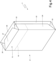
- the pack 1 for cigarettes comprises a cup-shaped container 2 made of carboard or rigid paperboard and a pair of wraps 3 (one of which is better illustrated in Figure 4 ) housed side by side inside the container 2.
- the container 2 has an open upper end and is provided with a lid 4, which is cup-shaped and is hinged to the container 2 along a hinge 5 (illustrated in Figure 2 ) for rotating, with respect to the container 2, between an open position (illustrated in Figure 3 ) and a closed position (illustrated in Figures 1 and 2 ) of the open upper end.
- the container 2 has a substantially rectangular parallelepiped shape oriented according to a main vertical development direction, is cup-shaped, and has the upper end open, a lower wall 6 opposite the open upper end, a front wall 7 and a rear wall 8 (where the hinge 5 is obtained) parallel to and opposite each other, and two side walls 9 parallel to and opposite each other.
- the lid 4 has a substantially rectangular parallelepiped shape, is cup-shaped, and has an open lower end, an upper wall 10, a front wall 11, a rear wall 12, and two side walls 13 parallel to and opposite each other.
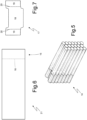
- Each wrap 3 encloses a group 14 of cigarettes (illustrated in Figure 5 ) having a parallelepiped shape. Furthermore, each wrap 3 has at the top and at the front a removable portion 15 which is separated from the remaining part of the wrap 3 by a pre-weakened tearable line 16; upon the first opening of the pack 1 for cigarettes, the user grabs and tears the removable portion 15 for accessing the underlying cigarettes of the group 14 of cigarettes.
- the pack 1 for cigarettes further comprises a rigid collar 17, which is connected (by means of gluing) folded in a "U"-shape inside the container 2 so as to partially project out of the open upper end of the container 2 and engage a corresponding inner surface of the lid 4 when the lid 4 is arranged in the closed position.
- the collar 17 comprises a front wall 18, which is connected to the front wall 7 of the container 2 and places itself in contact with the front wall 11 of the lid 4 when the lid 4 is in the closed position, and two side walls 19, which are connected to the side walls 9 of the container 2 and place themselves in contact with the side walls 13 of the lid 4 when the lid 4 is in the closed position.
- the front wall 18 of the collar 17 is provided with a pair of claws 20 which laterally project for engaging with interference the side walls 13 of the lid 4 when the lid 4 is in the closed position so as to maintain the lid 4 in the closed position.
- the front wall 18 of the collar 17 is without the claws 20.
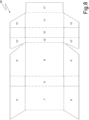
- each wrap 3 is made by folding around the group 14 of cigarettes a wrapping sheet 21 provided on a side of the tearable line 16 delimiting the removable portion 15.
- the wrapping sheet 21 is at first folded in a "U"-shape around the group 14 of cigarettes defining on the two minor side walls of the group 14 of cigarettes two open ends, each of which is delimited by a transverse flap 22 (or corner flap 22) and by two longitudinal fins 23 and 24.
- the transverse flap 22 is folded by 90° against the group 14 of cigarettes, then the longitudinal flap 23 is folded by 90° against the group 14 of cigarettes and over the previously folded transverse flap 22, and finally the longitudinal flap 24 is folded by 90° against the group 14 of cigarettes and over the previously folded (according to the folding modes known as "soap fold") transverse flap 22 and longitudinal flap 23; in this manner, the wrapping sheet 21 is given a tubular shape having one single open end in the area of the upper wall (where the filters of the cigarettes are arranged) of the group 14 of cigarettes; such open end is delimited by two transverse fins 25 (or corner fins 25) and by two longitudinal fins 26 and 27.
- the transverse fins 25 are folded by 90° against the group 14 of cigarettes, then the longitudinal flap 26 is folded by 90° against the group 14 of cigarettes and over the previously folded transverse fins 25, and finally the longitudinal flap 27 is folded by 90° against the group 14 of cigarettes and over the previously folded (according to the folding modes known as "soap fold") transverse fins 25 and longitudinal flap 26: in this manner, the folding of the wrapping sheet 21 around the group 14 of cigarettes is completed.
- the final shape of the wrapping sheet 21 around the group 14 of cigarettes is not stabilized in any manner (namely, glue is not applied to the wrapping sheet 21 and sealings are not made on the wrapping sheet 21); consequently, the final shape of the wrapping sheet 21 around the group 14 of cigarettes is maintained only by effect of the containment action of the container 2.
- each wrap 3 is of sealed type and has an extraction opening for extracting the cigarettes covered by a closing label which can be repositioned (namely, which can be opened and closed several times); in this embodiment, the wrapping sheet 21 is waterproof and the wrap 3 is stabilized by means of a transverse heat-sealing and by means of two longitudinal heat-sealings.
- the container 2 and the lid 4 are manufactured by folding a blank 28 of conventional type.
- reference numeral 29 indicates, as a whole, a packer machine which is designed to manufacture the above-described pack 1 for cigarettes and operates with an intermittent motion (namely, a motion which entails a cyclical alternation of motion phases and pause phases).
- the packer machine 29 comprises a frame 30 which rests on the ground by means of a plurality of feet (not illustrated) and is composed of the joining of two bodies 31 and 32 arranged side by side; in particular, the body 31 has a front wall and a side wall on which the operating members (partially described in the following) are arranged, whereas the body 32 (only) has a front wall on which all the operating members (partially described in the following) are arranged.
- the packer machine 29 comprises a forming unit A where the groups 14 of cigarettes are formed in sequence, a wrapping unit B where around each group 2 of cigarettes a respective wrapping sheet 21 is wrapped for making a wrap 3 and where the wraps 3 are grouped (coupled) two by two for forming the content of the packs 1 for cigarettes, and a wrapping unit C where around each pair of grouped (coupled) wraps 3 a collar 17 and a blank 28 are wrapped for manufacturing a container 2 provided with a lid 4.
- the forming unit A of the groups 14 of cigarettes comprises a hopper 33 provided with three outlets 34 for simultaneously feeding three groups 14 of cigarettes to three respective pockets 35 of a forming conveyor 36 which supports a plurality of pockets 35.
- the forming conveyor 36 comprises a conveyor belt having an annular shape, which is wound around two end pulleys (one of which is motorized), supports the pockets 35 and moves step by step for cyclically moving the pockets 35 along a forming path P1 (illustrated in Figure 10 ).
- the forming path P1 develops between an inlet station S1 where each group 14 of cigarettes is extracted from an outlet 34 of the hopper 33 and enters a corresponding pocket 35 and a transfer station S2 where each group 14 of cigarettes is extracted from the corresponding pocket 35.
- the wrapping unit B comprises a wrapping conveyor 37 designed to simultaneously convey two groups 14 of cigarettes next to each other (each of which is extracted from a pocket 35 of the forming conveyor 36 in the transfer station S2) along a straight and horizontal wrapping path P2; namely, the wrapping conveyor 37 is configured to simultaneously convey two groups 14 of cigarettes and two corresponding wrapping sheets 21 along the wrapping path P2.
- the wrapping path P2 extends from the transfer station S2 where the wrapping conveyor 37 extracts two groups 14 of cigarettes at a time from the corresponding pockets 35 of the forming conveyor 36, passes through a feeding station S3 where each group 14 of cigarettes couples to a corresponding wrapping sheet 21 (received in a receiving station S4) which folds in a "U"-shape around the group 14 of cigarettes, and ends in a transfer station S5 where each wrap 3 (formed by a wrapping sheet 21 partially folded around the group 14 of cigarettes) leaves the wrapping conveyor 37.
- the wrapping conveyor 37 comprises a conveyor belt having an annular shape, which is wound around two end pulleys (one of which is motorized) and supports a plurality of pairs of pushing elements, each of which is connected to the belt and is designed to engage a rear wall of a corresponding group 14 of cigarettes for pushing the group 14 of cigarettes along the wrapping path P2.
- each wrapping sheet 21 is arranged for being intercepted by a corresponding group 14 of cigarettes around which the wrapping sheet 21 folds in a "U"-shape; in other words, each group 14 of cigarettes moving along the wrapping path P2 intercepts a corresponding wrapping sheet 21 arranged in the feeding station S3 determining the folding in a "U"-shape of the wrapping sheet 21.
- each group 14 of cigarettes moving along the wrapping path P2 intercepts a corresponding wrapping sheet 21 arranged in the feeding station S3 determining the folding in a "U"-shape of the wrapping sheet 21.
- the wrapping unit B comprises a folding device 38 which is arranged along the wrapping path P2 downstream of the feeding station S3 and is designed, for each wrapping sheet 21, to initially fold by 90° and against the group 14 of cigarettes the two transverse flaps 22 and to subsequently fold by 90° and against the group 14 of cigarettes first the two longitudinal flaps 23 and then the longitudinal flaps 24 (according to the folding modes known as "soap fold").
- the folding device 38 is designed to fold two open side ends of each wrapping sheet 21 folded in a "U"-shape around a corresponding group 14 of cigarettes for forming a tubular wrap having an open rear end.
- the folding device 38 only comprises fixed folding profiles without moving parts.
- the wrapping unit B comprises a wrapping conveyor 39 designed to simultaneously convey two wraps 3 to be completed and next to each other (each of which comes from the wrapping conveyor 37) along a straight and horizontal wrapping path P3 which is perpendicular to the wrapping path P2.
- the wrapping path P3 extends from a transfer station S6 where the wrapping conveyor 39 simultaneously receives two wraps 3 to be completed and a transfer station S7 where the wrapping conveyor 39 simultaneously delivers two complete wraps 3.
- the wrapping conveyor 39 supports a plurality of pockets 40 each designed to house a wrap 3 and moves step by step for cyclically moving the pockets 40 along the wrapping path P3 from the transfer station S6 to the transfer station S7. Therefore, in the transfer station S6 two groups 14 of cigarettes wrapped in the respective wrapping sheets 21 (namely, the wraps 3 to be completed) and coming from the wrapping conveyor 37 simultaneously enter two respective pockets 40 of the wrapping conveyor 39.
- the wrapping unit B comprises a folding device 41 which is arranged along the wrapping path P3 downstream of the feeding station S6 and is designed, for each wrapping sheet 21, to initially fold by 90° and against the group 14 of cigarettes the two transverse flaps 25 and to subsequently fold by 90° and against the group 14 of cigarettes first the longitudinal flap 26 and then the longitudinal flap 27 (according to the folding modes known as "soap fold").
- a shuttle (transporter) 42 is interposed which is configured to simultaneously transport two wraps 3 to be completed from the transfer station S5 (namely, from the outlet of the wrapping conveyor 37) to the transfer station S6 (namely, to the inlet of the wrapping conveyor 39) along an extension of the wrapping path P2.
- the shuttle is movable back and forth for cyclically moving between the transfer station S5 and the transfer station S6.
- the packer machine 29 comprises a transport conveyor 43 which receives the complete wraps 3 from the wrapping unit B (and in particular from the wrapping conveyor 39) in the transfer station S7 and conveys the wraps 3 along a straight transport path P4 parallel to the wrapping path P3 (namely, perpendicular to the wrapping path P2) to a transfer station S8 (where the wraps 3 leave the transport conveyor 43).
- the transport conveyor 43 comprises a conveyor belt having an annular shape, which is wound around two end pulleys (one of which is motorized), supports a plurality of pockets 44 each designed to house a corresponding pair of wraps 3 next to each other (grouped), and moves step by step for cyclically moving the pockets 44 along the transport path P4 from the transfer station S7 to the transfer station S8. Therefore, in the transfer station S7 two wraps 3 are directly and simultaneously transferred from two respective pockets 40 of the wrapping conveyor 39 to a respective pocket 44 of the transport conveyor 43; namely, two wraps 3 simultaneously exit two respective pockets 40 of the wrapping conveyor 39 and simultaneously enter a respective pocket 44 of the transport conveyor 43.
- each pocket 44 of the transport conveyor 43 could comprise a very thin (for example having a thickness of 1-2 mm) dividing wall which divides the two wraps 3 of the same group of wraps 3 creating two single cells each designed to house one single wrap 3.
- the wrapping conveyor 39 is arranged between the wrapping conveyor 37 and the transport conveyor 43, cyclically receives from the wrapping conveyor 37 and in the transfer station S6 pairs of wraps 3 which are separated (namely, spaced apart from one another) and to be completed, and delivers pairs of complete wraps 3 next to one another (namely, arranged in substantial mutual contact) to the pockets 44 of the transport conveyor 43.
- the wrapping conveyor 39 is configured (besides to complete the folding of the wrapping sheets 21 cooperating with the folding device 41) also to bring the two wraps 3 of each pair of wraps 3 closer to each other so that in the transfer station S6 the two wraps 3 of each pair are farther from each other, whereas in the transfer station S7 the two groups of wraps 3 of each pair are closer to each other.
- the wrapping conveyor 39 is configured to divide the pockets 40 into two groups and to cause the pockets 40 of the two groups to have two different and alternated laws of motion (i.e. the same law of motion is applied one time to one group of pockets 40 and the next time to the other group of pockets 40) for cyclically changing a mutual distance between the pockets 40 of the two groups.
- the wrapping conveyor 39 comprises two belt conveyors 45 and 46 (better illustrated in Figure 11 ) wound like a ring around respective pulleys (one of which is motorized by means of respective motors 47 and 48): a belt conveyor 45 supports all the pockets 40 of one group and the other belt conveyor 46 supports all the pockets 40 of the other group and thus the pockets 40 of the two groups can be conveyed with different laws of motion (imparted in a manner independent of the two motors 47 and 48).
- the wrapping conveyor 39 is configured to bring the two wraps 3 closer to each other between the transfer station S6 and the transfer station S7.
- a pocket 40 belonging to one group namely, a pocket 40 moving along the wrapping path P3 following a first law of motion
- a pocket 40 belonging to the other group namely a pocket 40 moving along the wrapping path P3 following a second law of motion
- One law of motion entails a shorter travel T1 and the other law of motion entails a longer travel T2 so that, alternatively, all the pockets 40 of one group move along the wrapping path P3 along the shorter travel T1 and all the pockets 40 of the other group move along the wrapping path P3 along the longer travel T2.
- each pocket 40 moves along the wrapping path P3 carrying out the shorter travel T1 one time and the following time carrying out the longer travel T2 continuously alternating a short movement (travel T1) and a long movement (travel T2); furthermore, the two groups of pockets 40 always act in an opposite manner: while the pockets 40 of one group carry out the shorter travel T1, the pockets 40 of the other group carry out the longer travel T2 and vice versa.
- Figures 12-15 schematically illustrate a transferring device 49 configured to insert, in the transfer station S6, two wraps 3 to be completed coming from the wrapping conveyor 37 in two pockets 40 of the wrapping conveyor 39 and a transferring device 50 configured to extract, in the transfer station S7, two complete wraps 3 from two pockets 40 of the wrapping conveyor 39 and insert, in the transfer station S7, the two complete wraps 3 in a pocket 44 of the transport conveyor 43.
- the wrapping conveyor 39 alternates a pair of pockets 40 moving along the wrapping path P3 following a first law of motion with a pair of pockets 40 moving along the wrapping path P3 following a second law of motion, which is different from the first law of motion.
- the wrapping conveyor 39 alternates one single pocket 40 moving along the wrapping path P3 following a first law of motion with one single pocket 40 moving along the wrapping path P3 following a second law of motion, which is different from the first law of motion.
- the transferring device 50 is configured to simultaneously transfer two wraps 3 from two pockets 40 of the wrapping conveyor 39 to a pocket 44 of the transport conveyor 43 by means of a translation along a transfer direction D perpendicular to the wrapping path P3 and perpendicular to the transport path P4.
- the transferring device 50 comprises two conveyor belts 51 next to each other, each of which is wound like a ring, is arranged parallel to the transfer direction D, is arranged above the wrapping conveyor 39 and supports a series of pushing elements 52 each configured to push a wrap 3 from a pocket 40 of the wrapping conveyor 39 to a pocket 44 of the transport conveyor 43.
- the folding device 41 comprises fixed folding profiles 53 without moving parts and arranged parallel to the wrapping path P3 configured to fold against each group 14 of cigarettes the two longitudinal flaps 26 and 27 of the wrapping sheet 21; furthermore, the folding device 41 comprises three folding elements 54, 55 and 56 which are movable back and forth parallel to the wrapping path P3 for folding, against each group 14 of cigarettes, the two transverse flaps 25 of the respective wrapping sheet 21.
- the folding element 54 is arranged upstream of the two pockets 40 along the wrapping path P3
- the folding element 55 is arranged between the two pockets 40 along the wrapping path P3
- the folding element 56 is arranged downstream of the two pockets 40 along the wrapping path P3.
- the folding elements 54, 55 and 56 are moved along the wrapping path P3 by three respective actuator devices 57 which are independent of one another, namely are capable of moving the folding elements 54, 55 and 56 with different laws of motion.
- the actuator devices 57 are configured to move the folding element 54 forward at first and then backward along the wrapping path P3, to move the folding element 55 forward at first and then backward along the wrapping path P3, and to move the folding element 56 backward at first and then forward along the wrapping path P3.
- the wrapping conveyor 39 is configured to create pairs of wraps 3 next to one another utilizing two groups of pockets 40 having differentiated laws of motion; namely, the wrapping conveyor 39 is configured to receive in the transfer station S6 two wraps 3 (to be completed) farther from each other, to bring the two wraps 3 closer to each other during their completion, and thus to deliver in the transfer station S7 the two (complete) wraps 3 closer to each other (i.e. side by side).
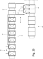
- the wrapping conveyor 39 is not configured to create pairs of wraps 3 next to one another (namely, does not modify the distance between the wraps 3), in the transfer station S7 two wraps 3 exit, still spaced apart from each other, the respective pockets 40 of the wrapping conveyor 39 (namely, in the transfer station S7 two wraps 3 have the same mutual distance that they had in the transfer station S6), and the two wraps 3 that exit the respective pockets 40 of the wrapping conveyor 39 in the transfer station S7 are joined (brought closer to each other) by means of the fixed profiles 58 which are shaped like a " funnel " and laterally push the two wraps 3 towards each other.
- the two wraps 3 that exit the two pockets 40 of the wrapping conveyor 39 in the transfer station S7 are laterally pushed towards each other by the fixed profiles 58 so as to bring the two wraps 3 closer to each other in the path from the wrapping conveyor 39 to the transport conveyor 43.
- the wrapping unit C of the packer machine 29 comprises a wrapping drum 59 which is arranged (immediately) downstream of the transport conveyor 43, supports a plurality of pockets each designed to contain a pair of wraps 3 and the collar 17, and is mounted so as to rotate (with an intermittent motion, namely in a " stepped " manner) around a horizontal rotation axis 60 parallel to the wrapping path P2 (and thus perpendicular to the wrapping path P3 and to the transport path P4) for moving each pocket along a wrapping path having a circular shape.
- Each pocket of the wrapping drum 59 receives a collar 17 in a feeding station arranged upstream of the transfer station S8, receives a pair of wraps 3 (which couples to the previously fed collar 17) in the transfer station S8 from the transport conveyor 43, and receives a blank 28 in a feeding station arranged downstream of the transfer station S8, and delivers together the pair of wraps 3, the collar 17 and the blank 28 to a following wrapping drum 61.
- the wrapping drum 61 supports a plurality of pockets each designed to contain a pair of wraps 3, the collar 17 and the blank 28, is mounted so as to rotate (with an intermittent motion, namely in a " stepped " manner) around a horizontal rotation axis 62 parallel to the rotation axis 60 and completes the folding of each blank 28 around the respective pair of wraps 3 coupled to the respective collar 17.
- the transport conveyor 43 is coupled to a feeding device configured to feed coupons to the wraps 3 carried by the pockets 44 of the transport conveyor 43.
- the wrapping unit B operates on a double line, namely along the wrapping path P2 two groups 14 of cigarettes are conveyed at a time; according to a different embodiment not illustrated, the wrapping unit B operates on a single line, namely along the wrapping path P2 one single group 14 of cigarettes is conveyed at a time.
- the pack 1 for cigarettes produced by the packer unit 29 is of "twin" type and contains a pair of wraps 3 housed side by side inside the container 2; according to a different embodiment not illustrated, the pack 1 for cigarettes produced by the packer unit 29 is of standard type and contains one single wrap 3 housed inside the container 2.
- the pockets 44 of the transport conveyor 43 are shaped for each housing only one wrap 3 and thus in this embodiment the wrapping conveyor 39 does not have to create pairs of wraps 3 next to one another and thus all the pockets 40 of the wrapping conveyor 39 have the same identical law of motion thus without the need for one group of pockets 40 to have a law of motion different from another group of pockets 40.
- one single folding element 54 is present; namely, the folding device 41 comprises the fixed folding profiles 53 configured to fold against each group 14 of cigarettes a first transverse flap 25 and two longitudinal flaps 26 and 27 of the wrapping sheet 21 and one single folding element 54 which is movable back and forth parallel to the wrapping path P3 for folding, against the group 14 of cigarettes, a second transverse flap 25 of the wrapping sheet 21.
- the pack 1 for cigarettes produced by the packer unit 29 is of "twin" type and contains a pair of wraps 3 housed side by side inside the container 2; according to a different embodiment not illustrated, the pack 1 for cigarettes produced by the packer unit 29 contains three wraps 3 housed side by side inside the container 2.
- the pockets 44 of the transport conveyor 43 are shaped for each housing three wraps 3 which are preferably brought closer to one another utilizing the fixed profiles 58 illustrated in Figures 24 and 25 (the two side wraps 3 are laterally pushed towards a central wrap 3 which remains transversely still and completes the set of three wraps 3 exiting the three pockets 40 of the wrapping conveyor 39).
- the wrapping conveyor 37 is configured to convey three groups 14 of cigarettes next to one another along the wrapping path P2.
- the moving of the various components (wrapping drums, feeding conveyors, pushing elements, movable folding elements/devices ...) of the packer machine 29 is obtained by means of respective electric motors which are mechanically independent of one another and are synchronized (namely, moved in phase) in a virtual manner (namely, not by means of a physical constraint, but by means of a control constraint).
- respective electric motors which are mechanically independent of one another and are synchronized (namely, moved in phase) in a virtual manner (namely, not by means of a physical constraint, but by means of a control constraint).
- the above-described packer machine 29 has numerous advantages.
- the above-described packer machine 29 allows operating at a high production speed (namely, with a high number of wraps 3 produced in the time unit) without damaging the wraps 3, namely guaranteeing a high final quality of the pack 1 for cigarettes.
- This result is obtained particularly thanks to the fact that the folding of the flaps 22-24 of each wrapping sheet 21 is performed along the wrapping path P2 which has the most favourable conditions for a folding of the flaps 22-24 (since along the wrapping path P2 the groups 14 of cigarettes move longitudinally) and the folding of the flaps 25-27 of each wrapping sheet 21 is performed along the wrapping path P3 which has the most favourable conditions for a folding of the flaps 25-27 (since along the wrapping path P3 the groups 14 of cigarettes move transversely).
- the shuttle 42 Since the fact that the folding of the wraps 3 is completed in the wrapping conveyor 39, the shuttle 42 must only carry out a transportation of the wraps 3 (to be completed) from the wrapping conveyor 37 to the wrapping conveyor 39 without carrying out any operation on the wraps 3 (to be completed); consequently, the shuttle 42 can operate without any problems more rapidly since it carries out one single operation (the transportation) which does not require a very high precision in the control of the position of the wraps 3 (to be completed).
- the above-described packer machine 29 allows changing the size of the packs 1 for cigarettes in a relatively simple and quick manner.
Landscapes
- Engineering & Computer Science (AREA)
- Mechanical Engineering (AREA)
- Wrapping Of Specific Fragile Articles (AREA)
- Basic Packing Technique (AREA)
Abstract
A packer machine (29) and a wrapping method to produce a rigid pack (1) for smoking articles having: at least one wrap (3) obtained by folding a wrapping sheet (21) around a group (14) of smoking articles, and an outer container (2) obtained by folding a blank (28) around the wrap (3). The following are provided: a first wrapping conveyor (37), which is configured to convey the group (14) of smoking articles and the wrapping sheet (21) along a straight and horizontal first wrapping path (P2); a first folding device (38) coupled to the first wrapping conveyor (37) and configured to fold the wrapping sheet (21) around the group (14) of smoking articles so as to form a tubular wrap having an open end; a second wrapping conveyor (39), which is arranged downstream of the first wrapping conveyor (37) and is configured to convey the group (14) of smoking articles and the wrapping sheet (21) along a second wrapping path (P3), which is straight and horizontal and perpendicular to the first wrapping path (P2); a second folding device (41) coupled to the second wrapping conveyor (39) and configured to complete the folding of the wrapping sheet (21) around the group (14) of smoking articles; and a transport conveyor (43), which is arranged downstream of the second wrapping conveyor (39).
Description
- This patent application claims priority from
Italian patent application no. 102023000027843 filed on December 22, 2023 - The present invention relates to a packer machine and to a wrapping method to produce a pack for smoking articles.
- The present invention is advantageously applied to the manufacturing of a rigid pack for cigarettes with a hinged lid, to which the following discussion will explicitly refer without thereby losing generality; the rigid pack for cigarettes can be either of single type (traditional) and thus containing one single wrap or can be of "twin" type and thus containing two wraps next to each other, in particular twin wraps.
- Rigid packs for cigarettes with a hinged lid are the most widespread packs for cigarettes currently on the market since they are simple to manufacture, easy and practical to use, and offer good protection to the cigarettes contained on their inside.
- A rigid pack for cigarettes with a hinged lid comprises a wrap consisting of a group of cigarettes wrapped in a wrapping sheet and a rigid outer casing which houses the wrap on its inside. The outer casing consists of a cup-shaped container, which houses the wrap and has an open upper end, and a lid, which is also cup-shaped and is hinged to the container so as to rotate, with respect to the container, between an open position and a closed position of the open end.
- Patent applications
EP4079648A1 ,EP4051595A1 ,EP4043350A1 andEP3725690A1 describe a packer machine for producing a rigid pack for cigarettes having a (at least one) wrap obtained by folding a wrapping sheet made of metallic paper around a group of cigarettes and an outer container obtained by folding a blank and a collar around the wrap. The packer machine comprises: a forming conveyor, which conveys a plurality of first pockets along a forming path; a hopper, which is arranged in front of the forming conveyor and along the forming path and is provided with at least one outlet from which at least one group of cigarettes can be extracted; a wrapping conveyor, which is arranged downstream of the forming conveyor and is designed to convey the group of cigarettes and the wrapping sheet along a straight and horizontal first wrapping path; a first wrapping drum, which is arranged downstream of the wrapping conveyor, supports at least a second pocket designed to contain the wrap and the collar, and is mounted so as to rotate around a first horizontal rotation axis parallel to the first wrapping path for conveying the second pocket along a circular second wrapping path; a second wrapping drum, which is arranged downstream of the first wrapping drum, supports at least a third pocket designed to contain the wrap, the collar and the blank, and is mounted so as to rotate around a second horizontal rotation axis parallel to the first rotation axis for conveying the third pocket along a circular third wrapping path; and a transport conveyor, which is interposed between the wrapping conveyor and the first wrapping drum and transfers the wrap from the wrapping conveyor to the first wrapping drum along a transport path perpendicular to the first wrapping path and perpendicular to the first rotation axis. - In the above-described packer machine, the folding of the wrapping sheet around the group of cigarettes is completed at the end of the straight and horizontal first wrapping path in a shuttle that transfers the group of cigarettes wrapped by the wrapping sheet from the wrapping conveyor to the transport conveyor: in fact, in order to be able to complete the folding of the wrapping sheet around the group of cigarettes, it is necessary to separate the group of cigarettes wrapped by the wrapping sheet from a pushing element of the wrapping conveyor so as to free the rear wall of the group of cigarettes engaged by the pushing element.
- The shuttle must be capable of holding the group of cigarettes guaranteeing high precision in the positioning of the group of cigarettes (a prerequisite condition in order to be able to perform quality folds when the folding of the wrapping sheet around the group of cigarettes is completed) without anyway compressing the group of cigarettes too much (so as not to cause undesired permanent deformations); namely, the shuttle must be capable of transporting the group of cigarettes without damaging the group of cigarettes due to an excessive compression of the group of cigarettes and, at the same time, without leaving the group of cigarettes excessively free so as to avoid an undesired uncontrolled loss of shape of the group of cigarettes. Furthermore, at every machine cycle, the shuttle must move quickly (thus with very high accelerations and decelerations) so as to remain still for a time sufficient to complete the folding of the wrapping sheet around the group of cigarettes.
- All these constraints prevent the shuttle (and thus the packer machine as a whole) from operating at very high operating speeds (above 500 machine cycles per minute) guaranteeing, at the same time, a high final quality of the packs for cigarettes (namely, guaranteeing that the packs for cigarettes have an extreme precision in all the folds).
- The object of the present invention is to provide a packer machine and a wrapping method for producing a pack for smoking articles which are simple to manufacture and implement, allow operating at a high production speed (measured as packs for cigarettes produced in the time unit), and allow, at the same time, guaranteeing a high final quality of the pack for smoking articles.
- In accordance with the present invention, a packer machine and a wrapping method for producing a pack for smoking articles are provided, according to what is claimed in the appended claims.
- In accordance with the present invention, a packer machine and a wrapping method are provided, according to what is claimed in the appended claims.
- The claims describe embodiments of the present invention forming integral part of the present description.
- The present invention will now be described with reference to the accompanying drawings, which illustrate a non-limiting example embodiment thereof, wherein:
-
Figure 1 is a front perspective view in a closed configuration of a rigid pack for cigarettes; -
Figure 2 is a rear perspective view of the pack for cigarettes ofFigure 1 in a closed configuration; -
Figure 3 is a front perspective view of the pack for cigarettes ofFigure 1 in an open configuration; -
Figure 4 is a front perspective view of a wrap of the pack ofFigure 1 ; -
Figure 5 is a perspective view of a group of cigarettes contained in the wrap ofFigure 4 ; -
Figure 6 is a plan view of a wrapping sheet utilized for manufacturing the wrap ofFigure 4 ; -
Figure 7 is a plan view of a collar of the pack for cigarettes ofFigure 1 ; -
Figure 8 is a plan view of a blank utilized for manufacturing an outer container provided with a hinged lid of the pack for cigarettes ofFigure 1 ; -
Figure 9 is a schematic perspective view, with parts removed for clarity, of a packer machine which produces the pack for cigarettes ofFigure 1 and is manufactured in accordance with the present invention; -
Figure 10 is a schematic plan view of part of the packer machine ofFigure 9 ; -
Figure 11 is a perspective view, with parts removed for clarity, of a wrapping conveyor and of a transport conveyor of the packer machine ofFigure 9 ; -
Figures 12-15 schematically illustrate the operation of the wrapping conveyor ofFigure 11 ; -
Figures 16-19 schematically illustrate the operation of a folding device coupled to the wrapping conveyor ofFigure 11 ; -
Figures 20-23 schematically illustrate the operation of a different embodiment of the wrapping conveyor ofFigure 11 ; and -
Figures 24 and25 schematically illustrate the operation of a further embodiment of the wrapping conveyor ofFigure 11 . - In
Figures 1, 2 and3 ,reference numeral 1 indicates, as a whole, a "twin" rigid pack for cigarettes. Thepack 1 for cigarettes comprises a cup-shaped container 2 made of carboard or rigid paperboard and a pair of wraps 3 (one of which is better illustrated inFigure 4 ) housed side by side inside thecontainer 2. - The
container 2 has an open upper end and is provided with alid 4, which is cup-shaped and is hinged to thecontainer 2 along a hinge 5 (illustrated inFigure 2 ) for rotating, with respect to thecontainer 2, between an open position (illustrated inFigure 3 ) and a closed position (illustrated inFigures 1 and 2 ) of the open upper end. - The
container 2 has a substantially rectangular parallelepiped shape oriented according to a main vertical development direction, is cup-shaped, and has the upper end open, alower wall 6 opposite the open upper end, afront wall 7 and a rear wall 8 (where thehinge 5 is obtained) parallel to and opposite each other, and twoside walls 9 parallel to and opposite each other. Thelid 4 has a substantially rectangular parallelepiped shape, is cup-shaped, and has an open lower end, anupper wall 10, afront wall 11, arear wall 12, and twoside walls 13 parallel to and opposite each other. - Each
wrap 3 encloses agroup 14 of cigarettes (illustrated inFigure 5 ) having a parallelepiped shape. Furthermore, eachwrap 3 has at the top and at the front aremovable portion 15 which is separated from the remaining part of thewrap 3 by a pre-weakenedtearable line 16; upon the first opening of thepack 1 for cigarettes, the user grabs and tears theremovable portion 15 for accessing the underlying cigarettes of thegroup 14 of cigarettes. - According to what is illustrated in
Figures 3 and7 , thepack 1 for cigarettes further comprises arigid collar 17, which is connected (by means of gluing) folded in a "U"-shape inside thecontainer 2 so as to partially project out of the open upper end of thecontainer 2 and engage a corresponding inner surface of thelid 4 when thelid 4 is arranged in the closed position. Thecollar 17 comprises afront wall 18, which is connected to thefront wall 7 of thecontainer 2 and places itself in contact with thefront wall 11 of thelid 4 when thelid 4 is in the closed position, and twoside walls 19, which are connected to theside walls 9 of thecontainer 2 and place themselves in contact with theside walls 13 of thelid 4 when thelid 4 is in the closed position. According to the embodiment illustrated in the accompanying figures, thefront wall 18 of thecollar 17 is provided with a pair ofclaws 20 which laterally project for engaging with interference theside walls 13 of thelid 4 when thelid 4 is in the closed position so as to maintain thelid 4 in the closed position. According to a different embodiment not illustrated, thefront wall 18 of thecollar 17 is without theclaws 20. - According to what is illustrated in
Figure 6 , eachwrap 3 is made by folding around thegroup 14 of cigarettes awrapping sheet 21 provided on a side of thetearable line 16 delimiting theremovable portion 15. According to what is illustrated inFigure 4 , thewrapping sheet 21 is at first folded in a "U"-shape around thegroup 14 of cigarettes defining on the two minor side walls of thegroup 14 of cigarettes two open ends, each of which is delimited by a transverse flap 22 (or corner flap 22) and by twolongitudinal fins transverse flap 22 is folded by 90° against thegroup 14 of cigarettes, then thelongitudinal flap 23 is folded by 90° against thegroup 14 of cigarettes and over the previously foldedtransverse flap 22, and finally thelongitudinal flap 24 is folded by 90° against thegroup 14 of cigarettes and over the previously folded (according to the folding modes known as "soap fold")transverse flap 22 andlongitudinal flap 23; in this manner, thewrapping sheet 21 is given a tubular shape having one single open end in the area of the upper wall (where the filters of the cigarettes are arranged) of thegroup 14 of cigarettes; such open end is delimited by two transverse fins 25 (or corner fins 25) and by twolongitudinal fins transverse fins 25 are folded by 90° against thegroup 14 of cigarettes, then thelongitudinal flap 26 is folded by 90° against thegroup 14 of cigarettes and over the previously foldedtransverse fins 25, and finally thelongitudinal flap 27 is folded by 90° against thegroup 14 of cigarettes and over the previously folded (according to the folding modes known as "soap fold")transverse fins 25 and longitudinal flap 26: in this manner, the folding of thewrapping sheet 21 around thegroup 14 of cigarettes is completed. - According to a preferred embodiment, the final shape of the
wrapping sheet 21 around thegroup 14 of cigarettes is not stabilized in any manner (namely, glue is not applied to thewrapping sheet 21 and sealings are not made on the wrapping sheet 21); consequently, the final shape of thewrapping sheet 21 around thegroup 14 of cigarettes is maintained only by effect of the containment action of thecontainer 2. - According to a different embodiment non illustrated, each
wrap 3 is of sealed type and has an extraction opening for extracting the cigarettes covered by a closing label which can be repositioned (namely, which can be opened and closed several times); in this embodiment, thewrapping sheet 21 is waterproof and thewrap 3 is stabilized by means of a transverse heat-sealing and by means of two longitudinal heat-sealings. - According to what is illustrated in
Figure 8 , thecontainer 2 and thelid 4 are manufactured by folding a blank 28 of conventional type. - In
Figure 9 ,reference numeral 29 indicates, as a whole, a packer machine which is designed to manufacture the above-describedpack 1 for cigarettes and operates with an intermittent motion (namely, a motion which entails a cyclical alternation of motion phases and pause phases). - The
packer machine 29 comprises aframe 30 which rests on the ground by means of a plurality of feet (not illustrated) and is composed of the joining of twobodies body 31 has a front wall and a side wall on which the operating members (partially described in the following) are arranged, whereas the body 32 (only) has a front wall on which all the operating members (partially described in the following) are arranged. - The
packer machine 29 comprises a forming unit A where thegroups 14 of cigarettes are formed in sequence, a wrapping unit B where around eachgroup 2 of cigarettes arespective wrapping sheet 21 is wrapped for making awrap 3 and where thewraps 3 are grouped (coupled) two by two for forming the content of thepacks 1 for cigarettes, and a wrapping unit C where around each pair of grouped (coupled) wraps 3 acollar 17 and a blank 28 are wrapped for manufacturing acontainer 2 provided with alid 4. - The forming unit A of the
groups 14 of cigarettes comprises ahopper 33 provided with threeoutlets 34 for simultaneously feeding threegroups 14 of cigarettes to threerespective pockets 35 of a formingconveyor 36 which supports a plurality ofpockets 35. The formingconveyor 36 comprises a conveyor belt having an annular shape, which is wound around two end pulleys (one of which is motorized), supports thepockets 35 and moves step by step for cyclically moving thepockets 35 along a forming path P1 (illustrated inFigure 10 ). According to what is better illustrated inFigure 10 , the forming path P1 develops between an inlet station S1 where eachgroup 14 of cigarettes is extracted from anoutlet 34 of thehopper 33 and enters acorresponding pocket 35 and a transfer station S2 where eachgroup 14 of cigarettes is extracted from thecorresponding pocket 35. - According to what is illustrated in
Figure 10 , the wrapping unit B comprises awrapping conveyor 37 designed to simultaneously convey twogroups 14 of cigarettes next to each other (each of which is extracted from apocket 35 of the formingconveyor 36 in the transfer station S2) along a straight and horizontal wrapping path P2; namely, thewrapping conveyor 37 is configured to simultaneously convey twogroups 14 of cigarettes and twocorresponding wrapping sheets 21 along the wrapping path P2. In particular, the wrapping path P2 extends from the transfer station S2 where thewrapping conveyor 37 extracts twogroups 14 of cigarettes at a time from thecorresponding pockets 35 of the formingconveyor 36, passes through a feeding station S3 where eachgroup 14 of cigarettes couples to a corresponding wrapping sheet 21 (received in a receiving station S4) which folds in a "U"-shape around thegroup 14 of cigarettes, and ends in a transfer station S5 where each wrap 3 (formed by awrapping sheet 21 partially folded around thegroup 14 of cigarettes) leaves the wrappingconveyor 37. - The wrapping
conveyor 37 comprises a conveyor belt having an annular shape, which is wound around two end pulleys (one of which is motorized) and supports a plurality of pairs of pushing elements, each of which is connected to the belt and is designed to engage a rear wall of acorresponding group 14 of cigarettes for pushing thegroup 14 of cigarettes along the wrapping path P2. - Along the wrapping path P2 (and thus in the area of the wrapping conveyor 37), the feeding station S3 is present where each wrapping
sheet 21 is arranged for being intercepted by a correspondinggroup 14 of cigarettes around which thewrapping sheet 21 folds in a "U"-shape; in other words, eachgroup 14 of cigarettes moving along the wrapping path P2 intercepts acorresponding wrapping sheet 21 arranged in the feeding station S3 determining the folding in a "U"-shape of thewrapping sheet 21. For further details on the feeding station S3 reference is made to what is described in patentapplication EP3725691A1 . - According to what is illustrated in
Figure 10 , the wrapping unit B comprises afolding device 38 which is arranged along the wrapping path P2 downstream of the feeding station S3 and is designed, for each wrappingsheet 21, to initially fold by 90° and against thegroup 14 of cigarettes the twotransverse flaps 22 and to subsequently fold by 90° and against thegroup 14 of cigarettes first the twolongitudinal flaps 23 and then the longitudinal flaps 24 (according to the folding modes known as "soap fold"). Namely, thefolding device 38 is designed to fold two open side ends of each wrappingsheet 21 folded in a "U"-shape around a correspondinggroup 14 of cigarettes for forming a tubular wrap having an open rear end. According to a preferred embodiment, thefolding device 38 only comprises fixed folding profiles without moving parts. - According to what is illustrated in
Figure 10 , the wrapping unit B comprises a wrappingconveyor 39 designed to simultaneously convey twowraps 3 to be completed and next to each other (each of which comes from the wrapping conveyor 37) along a straight and horizontal wrapping path P3 which is perpendicular to the wrapping path P2. In particular, the wrapping path P3 extends from a transfer station S6 where the wrappingconveyor 39 simultaneously receives twowraps 3 to be completed and a transfer station S7 where the wrappingconveyor 39 simultaneously delivers twocomplete wraps 3. According to what is illustrated inFigure 11 , the wrappingconveyor 39 supports a plurality ofpockets 40 each designed to house awrap 3 and moves step by step for cyclically moving thepockets 40 along the wrapping path P3 from the transfer station S6 to the transfer station S7. Therefore, in the transfer station S6 twogroups 14 of cigarettes wrapped in the respective wrapping sheets 21 (namely, thewraps 3 to be completed) and coming from the wrappingconveyor 37 simultaneously enter tworespective pockets 40 of the wrappingconveyor 39. - According to what is illustrated in
Figure 10 , the wrapping unit B comprises afolding device 41 which is arranged along the wrapping path P3 downstream of the feeding station S6 and is designed, for each wrappingsheet 21, to initially fold by 90° and against thegroup 14 of cigarettes the twotransverse flaps 25 and to subsequently fold by 90° and against thegroup 14 of cigarettes first thelongitudinal flap 26 and then the longitudinal flap 27 (according to the folding modes known as "soap fold"). - Between the wrapping
conveyor 37 and the wrappingconveyor 39, a shuttle (transporter) 42 is interposed which is configured to simultaneously transport twowraps 3 to be completed from the transfer station S5 (namely, from the outlet of the wrapping conveyor 37) to the transfer station S6 (namely, to the inlet of the wrapping conveyor 39) along an extension of the wrapping path P2. The shuttle is movable back and forth for cyclically moving between the transfer station S5 and the transfer station S6. - According to what is illustrated in
Figures 9 and10 , thepacker machine 29 comprises atransport conveyor 43 which receives thecomplete wraps 3 from the wrapping unit B (and in particular from the wrapping conveyor 39) in the transfer station S7 and conveys thewraps 3 along a straight transport path P4 parallel to the wrapping path P3 (namely, perpendicular to the wrapping path P2) to a transfer station S8 (where thewraps 3 leave the transport conveyor 43). According to what is illustrated inFigure 11 , thetransport conveyor 43 comprises a conveyor belt having an annular shape, which is wound around two end pulleys (one of which is motorized), supports a plurality ofpockets 44 each designed to house a corresponding pair ofwraps 3 next to each other (grouped), and moves step by step for cyclically moving thepockets 44 along the transport path P4 from the transfer station S7 to the transfer station S8. Therefore, in the transfer station S7 twowraps 3 are directly and simultaneously transferred from tworespective pockets 40 of the wrappingconveyor 39 to arespective pocket 44 of thetransport conveyor 43; namely, twowraps 3 simultaneously exit tworespective pockets 40 of the wrappingconveyor 39 and simultaneously enter arespective pocket 44 of thetransport conveyor 43. - According to a possible embodiment, each
pocket 44 of thetransport conveyor 43 could comprise a very thin (for example having a thickness of 1-2 mm) dividing wall which divides the twowraps 3 of the same group ofwraps 3 creating two single cells each designed to house onesingle wrap 3. - The wrapping
conveyor 39 is arranged between the wrappingconveyor 37 and thetransport conveyor 43, cyclically receives from the wrappingconveyor 37 and in the transfer station S6 pairs ofwraps 3 which are separated (namely, spaced apart from one another) and to be completed, and delivers pairs ofcomplete wraps 3 next to one another (namely, arranged in substantial mutual contact) to thepockets 44 of thetransport conveyor 43. In other words, the wrappingconveyor 39 is configured (besides to complete the folding of thewrapping sheets 21 cooperating with the folding device 41) also to bring the twowraps 3 of each pair ofwraps 3 closer to each other so that in the transfer station S6 the twowraps 3 of each pair are farther from each other, whereas in the transfer station S7 the two groups ofwraps 3 of each pair are closer to each other. - According to what is illustrated in
Figures 12-15 , the wrappingconveyor 39 is configured to divide thepockets 40 into two groups and to cause thepockets 40 of the two groups to have two different and alternated laws of motion (i.e. the same law of motion is applied one time to one group ofpockets 40 and the next time to the other group of pockets 40) for cyclically changing a mutual distance between thepockets 40 of the two groups. In particular, the wrappingconveyor 39 comprises twobelt conveyors 45 and 46 (better illustrated inFigure 11 ) wound like a ring around respective pulleys (one of which is motorized by means ofrespective motors 47 and 48): abelt conveyor 45 supports all thepockets 40 of one group and theother belt conveyor 46 supports all thepockets 40 of the other group and thus thepockets 40 of the two groups can be conveyed with different laws of motion (imparted in a manner independent of the twomotors 47 and 48). - In this manner, the two
pockets 40 which are in the transfer station S6 are always farther from each other, whereas the twopockets 40 which are in the transfer station S7 are always closer to each other; consequently, the wrappingconveyor 39 is configured to bring the twowraps 3 closer to each other between the transfer station S6 and the transfer station S7. - In particular, a
pocket 40 belonging to one group (namely, apocket 40 moving along the wrapping path P3 following a first law of motion) and apocket 40 belonging to the other group (namely apocket 40 moving along the wrapping path P3 following a second law of motion) are always standing still in the transfer stations S6 and S7. - One law of motion entails a shorter travel T1 and the other law of motion entails a longer travel T2 so that, alternatively, all the
pockets 40 of one group move along the wrapping path P3 along the shorter travel T1 and all thepockets 40 of the other group move along the wrapping path P3 along the longer travel T2. In other words, eachpocket 40 moves along the wrapping path P3 carrying out the shorter travel T1 one time and the following time carrying out the longer travel T2 continuously alternating a short movement (travel T1) and a long movement (travel T2); furthermore, the two groups ofpockets 40 always act in an opposite manner: while thepockets 40 of one group carry out the shorter travel T1, thepockets 40 of the other group carry out the longer travel T2 and vice versa. -
Figures 12-15 schematically illustrate a transferringdevice 49 configured to insert, in the transfer station S6, twowraps 3 to be completed coming from the wrappingconveyor 37 in twopockets 40 of the wrappingconveyor 39 and a transferringdevice 50 configured to extract, in the transfer station S7, twocomplete wraps 3 from twopockets 40 of the wrappingconveyor 39 and insert, in the transfer station S7, the twocomplete wraps 3 in apocket 44 of thetransport conveyor 43. - In the embodiment illustrated in
Figures 12-15 , the wrappingconveyor 39 alternates a pair ofpockets 40 moving along the wrapping path P3 following a first law of motion with a pair ofpockets 40 moving along the wrapping path P3 following a second law of motion, which is different from the first law of motion. In the alternative embodiment illustrated inFigures 20-23 , the wrappingconveyor 39 alternates onesingle pocket 40 moving along the wrapping path P3 following a first law of motion with onesingle pocket 40 moving along the wrapping path P3 following a second law of motion, which is different from the first law of motion. - According to a preferred embodiment illustrated in
Figure 11 , the transferringdevice 50 is configured to simultaneously transfer twowraps 3 from twopockets 40 of the wrappingconveyor 39 to apocket 44 of thetransport conveyor 43 by means of a translation along a transfer direction D perpendicular to the wrapping path P3 and perpendicular to the transport path P4. The transferringdevice 50 comprises twoconveyor belts 51 next to each other, each of which is wound like a ring, is arranged parallel to the transfer direction D, is arranged above the wrappingconveyor 39 and supports a series of pushingelements 52 each configured to push awrap 3 from apocket 40 of the wrappingconveyor 39 to apocket 44 of thetransport conveyor 43. - According to what is illustrated in
Figures 16-19 , thefolding device 41 comprises fixed folding profiles 53 without moving parts and arranged parallel to the wrapping path P3 configured to fold against eachgroup 14 of cigarettes the twolongitudinal flaps wrapping sheet 21; furthermore, thefolding device 41 comprises threefolding elements group 14 of cigarettes, the twotransverse flaps 25 of therespective wrapping sheet 21. - When the two
groups 14 of cigarettes and the twocorresponding wrapping sheets 21 enter the twopockets 40 of the wrappingconveyor 39 in the transfer station S6 (as is illustrated inFigure 16 ), thefolding element 54 is arranged upstream of the twopockets 40 along the wrapping path P3, thefolding element 55 is arranged between the twopockets 40 along the wrapping path P3, and thefolding element 56 is arranged downstream of the twopockets 40 along the wrapping path P3. Thefolding elements respective actuator devices 57 which are independent of one another, namely are capable of moving thefolding elements - Subsequently and as is illustrated in
Figures 17 ,18 and 19 , theactuator devices 57 are configured to move thefolding element 54 forward at first and then backward along the wrapping path P3, to move thefolding element 55 forward at first and then backward along the wrapping path P3, and to move thefolding element 56 backward at first and then forward along the wrapping path P3. - In the embodiment illustrated in
Figures 12-15 and22-23 , the wrappingconveyor 39 is configured to create pairs ofwraps 3 next to one another utilizing two groups ofpockets 40 having differentiated laws of motion; namely, the wrappingconveyor 39 is configured to receive in the transfer station S6 two wraps 3 (to be completed) farther from each other, to bring the twowraps 3 closer to each other during their completion, and thus to deliver in the transfer station S7 the two (complete) wraps 3 closer to each other (i.e. side by side). - In the alternative embodiment illustrated in
Figures 24 and25 , the wrappingconveyor 39 is not configured to create pairs ofwraps 3 next to one another (namely, does not modify the distance between the wraps 3), in the transfer station S7 twowraps 3 exit, still spaced apart from each other, therespective pockets 40 of the wrapping conveyor 39 (namely, in the transfer station S7 twowraps 3 have the same mutual distance that they had in the transfer station S6), and the twowraps 3 that exit therespective pockets 40 of the wrappingconveyor 39 in the transfer station S7 are joined (brought closer to each other) by means of the fixedprofiles 58 which are shaped like a "funnel" and laterally push the twowraps 3 towards each other. Namely, the twowraps 3 that exit the twopockets 40 of the wrappingconveyor 39 in the transfer station S7 are laterally pushed towards each other by the fixedprofiles 58 so as to bring the twowraps 3 closer to each other in the path from the wrappingconveyor 39 to thetransport conveyor 43. - According to what is illustrated in
Figure 9 , the wrapping unit C of thepacker machine 29 comprises a wrappingdrum 59 which is arranged (immediately) downstream of thetransport conveyor 43, supports a plurality of pockets each designed to contain a pair ofwraps 3 and thecollar 17, and is mounted so as to rotate (with an intermittent motion, namely in a "stepped" manner) around ahorizontal rotation axis 60 parallel to the wrapping path P2 (and thus perpendicular to the wrapping path P3 and to the transport path P4) for moving each pocket along a wrapping path having a circular shape. Each pocket of the wrappingdrum 59 receives acollar 17 in a feeding station arranged upstream of the transfer station S8, receives a pair of wraps 3 (which couples to the previously fed collar 17) in the transfer station S8 from thetransport conveyor 43, and receives a blank 28 in a feeding station arranged downstream of the transfer station S8, and delivers together the pair ofwraps 3, thecollar 17 and the blank 28 to a following wrappingdrum 61. - The wrapping
drum 61 supports a plurality of pockets each designed to contain a pair ofwraps 3, thecollar 17 and the blank 28, is mounted so as to rotate (with an intermittent motion, namely in a "stepped" manner) around ahorizontal rotation axis 62 parallel to therotation axis 60 and completes the folding of each blank 28 around the respective pair ofwraps 3 coupled to therespective collar 17. - According to a possible embodiment, the
transport conveyor 43 is coupled to a feeding device configured to feed coupons to thewraps 3 carried by thepockets 44 of thetransport conveyor 43. - For further details on the wrapping unit C reference is made to what is described in patent application
EP3725691A1 . - In the embodiment illustrated in the accompanying figures, the wrapping unit B operates on a double line, namely along the wrapping path P2 two
groups 14 of cigarettes are conveyed at a time; according to a different embodiment not illustrated, the wrapping unit B operates on a single line, namely along the wrapping path P2 onesingle group 14 of cigarettes is conveyed at a time. - In the embodiment illustrated in the accompanying figures, the
pack 1 for cigarettes produced by thepacker unit 29 is of "twin" type and contains a pair ofwraps 3 housed side by side inside thecontainer 2; according to a different embodiment not illustrated, thepack 1 for cigarettes produced by thepacker unit 29 is of standard type and contains onesingle wrap 3 housed inside thecontainer 2. In this embodiment, thepockets 44 of thetransport conveyor 43 are shaped for each housing only onewrap 3 and thus in this embodiment the wrappingconveyor 39 does not have to create pairs ofwraps 3 next to one another and thus all thepockets 40 of the wrappingconveyor 39 have the same identical law of motion thus without the need for one group ofpockets 40 to have a law of motion different from another group ofpockets 40. Furthermore, in this embodiment onesingle folding element 54 is present; namely, thefolding device 41 comprises the fixed folding profiles 53 configured to fold against eachgroup 14 of cigarettes a firsttransverse flap 25 and twolongitudinal flaps wrapping sheet 21 and onesingle folding element 54 which is movable back and forth parallel to the wrapping path P3 for folding, against thegroup 14 of cigarettes, a secondtransverse flap 25 of thewrapping sheet 21. - In the embodiment illustrated in the accompanying figures, the
pack 1 for cigarettes produced by thepacker unit 29 is of "twin" type and contains a pair ofwraps 3 housed side by side inside thecontainer 2; according to a different embodiment not illustrated, thepack 1 for cigarettes produced by thepacker unit 29 contains threewraps 3 housed side by side inside thecontainer 2. In this embodiment, thepockets 44 of thetransport conveyor 43 are shaped for each housing threewraps 3 which are preferably brought closer to one another utilizing the fixedprofiles 58 illustrated inFigures 24 and25 (the two side wraps 3 are laterally pushed towards acentral wrap 3 which remains transversely still and completes the set of threewraps 3 exiting the threepockets 40 of the wrapping conveyor 39). In this embodiment, the wrappingconveyor 37 is configured to convey threegroups 14 of cigarettes next to one another along the wrapping path P2. - According to a preferred, but not constraining, embodiment, the moving of the various components (wrapping drums, feeding conveyors, pushing elements, movable folding elements/devices ...) of the
packer machine 29 is obtained by means of respective electric motors which are mechanically independent of one another and are synchronized (namely, moved in phase) in a virtual manner (namely, not by means of a physical constraint, but by means of a control constraint). Normally, an electric motor is considered as reference ("master") and all the other electric motors ("slave") follow the position of the electric motor of reference ("master"). - The embodiments described herein can be combined with one another without departing from the scope of protection of the present invention.
- The above-described
packer machine 29 has numerous advantages. - First of all, the above-described
packer machine 29 allows operating at a high production speed (namely, with a high number ofwraps 3 produced in the time unit) without damaging thewraps 3, namely guaranteeing a high final quality of thepack 1 for cigarettes. This result is obtained particularly thanks to the fact that the folding of the flaps 22-24 of each wrappingsheet 21 is performed along the wrapping path P2 which has the most favourable conditions for a folding of the flaps 22-24 (since along the wrapping path P2 thegroups 14 of cigarettes move longitudinally) and the folding of the flaps 25-27 of each wrappingsheet 21 is performed along the wrapping path P3 which has the most favourable conditions for a folding of the flaps 25-27 (since along the wrapping path P3 thegroups 14 of cigarettes move transversely). Thanks to the fact that the folding of thewraps 3 is completed in the wrappingconveyor 39, theshuttle 42 must only carry out a transportation of the wraps 3 (to be completed) from the wrappingconveyor 37 to the wrappingconveyor 39 without carrying out any operation on the wraps 3 (to be completed); consequently, theshuttle 42 can operate without any problems more rapidly since it carries out one single operation (the transportation) which does not require a very high precision in the control of the position of the wraps 3 (to be completed). - Furthermore, the above-described
packer machine 29 allows changing the size of thepacks 1 for cigarettes in a relatively simple and quick manner. - It is important to observe that the presence of the wrapping
conveyor 39 is essential since it would be extremely complicated to complete the folding of thewraps 3 along thetransport conveyor 43 where thepockets 40 must be open at the top for allowing the transfer from the bottom upward of thecomplete wraps 3 towards the wrappingdrum 59 in the transfer station S8. Among other things, if the folding of thewraps 3 were completed along thetransport conveyor 43, it would be impossible to feed the coupons along thetransport conveyor 43. - The embodiment illustrated in the accompanying figures refers to the manufacturing of a pack for cigarettes, but the present invention is also applicable without substantial modifications to the manufacturing of any other type of pack for smoking articles (for example a pack for cigars, a pack for electronic cigarettes of the liquid vaporization type, a pack for new generation cigarettes without tobacco combustion...).
-
- 1
- pack for cigarettes
- 2
- container
- 3
- wrap
- 4
- lid
- 5
- hinge
- 6
- lower wall
- 7
- front wall
- 8
- rear wall
- 9
- side walls
- 10
- upper wall
- 11
- front wall
- 12
- rear wall
- 13
- side walls
- 14
- group of cigarettes
- 15
- removable portion
- 16
- tearable line
- 17
- collar
- 18
- front wall
- 19
- side walls
- 20
- claws
- 21
- wrapping sheet
- 22
- transverse flap
- 23
- longitudinal flap
- 24
- longitudinal flap
- 25
- transverse flap
- 26
- longitudinal flap
- 27
- longitudinal flap
- 28
- blank
- 29
- packer machine
- 30
- frame
- 31
- body
- 32
- body
- 33
- hopper
- 34
- outlets
- 35
- pockets
- 36
- forming conveyor
- 37
- wrapping conveyor
- 38
- folding device
- 39
- wrapping conveyor
- 40
- pockets
- 41
- folding device
- 42
- shuttle
- 43
- transport conveyor
- 44
- pockets
- 45
- conveyor belt
- 46
- conveyor belt
- 47
- motor
- 48
- motor
- 49
- transferring device
- 50
- transferring device
- 51
- conveyor belt
- 52
- pushing element
- 53
- fixed folding profiles
- 54
- folding element
- 55
- folding element
- 56
- folding element
- 57
- actuator device
- 58
- fixed profiles
- 59
- wrapping drum
- 60
- rotation axis
- 61
- wrapping drum
- 62
- rotation axis
- P1
- forming path
- P2
- wrapping path
- P3
- wrapping path
- P4
- transport path
- S1
- inlet station
- S2
- transfer station
- S3
- feeding station
- S4
- receiving station
- S5
- transfer station
- S6
- transfer station
- S7
- transfer station
- S8
- transfer station
- A
- forming unit
- B
- wrapping unit
- C
- wrapping unit
- D
- transfer direction
- T1
- travel
- T2
- travel
Claims (20)
- A packer machine (29) to produce a rigid pack (1) for smoking articles comprising: at least one wrap (3) obtained by folding a wrapping sheet (21) around a group (14) of smoking articles, and an outer container (2) obtained by folding a blank (28) around the wrap (3); the packer machine (29) comprises:a first wrapping conveyor (37), which is configured to convey the group (14) of smoking articles and the wrapping sheet (21) along a straight and horizontal first wrapping path (P2);a first folding device (38) coupled to the first wrapping conveyor (37) and configured to fold the wrapping sheet (21) around the group (14) of smoking articles so as to form a tubular wrap having an open end;at least one wrapping drum (59), which is arranged downstream of the first wrapping conveyor (37), is mounted so as to rotate around a horizontal rotation axis (60) parallel to the first wrapping path (P2) and is configured to fold the blank (28) around the wrap (3); a transport conveyor (43), which is arranged between the first wrapping conveyor (37) and the first wrapping drum (59), comprises a first pocket (44) designed to contain the wrap (3) and is configured to transfer the wrap (3) to the first wrapping drum (59) along a transport path (P4) perpendicular to the first wrapping drum (P2) and perpendicular to the rotation axis (60);a second wrapping conveyor (39), which is arranged between the first wrapping conveyor (37) and the transport conveyor (43), comprises a second pocket (40) designed to contain the group (14) of smoking articles and the wrapping sheet (21) and is configured to convey the group (14) of smoking articles and the wrapping sheet (21) along a second wrapping path (P3), which is straight and horizontal, is perpendicular to the first wrapping path (P2) and is parallel to the transport path (P4); anda second folding device (41) coupled to the second wrapping conveyor (39) and configured to complete the folding of the wrapping sheet (21) around the group (14) of smoking articles;the packer machine (29) is characterized in that the second folding device (41) is arranged along the second wrapping path (P3) and is configured to complete the folding of the wrapping sheet (21) around the group (14) of smoking articles solely when the group (14) of smoking articles is inserted in the second pocket (40) and moves along the second wrapping path (P3).
- The packer machine (29) according to claim 1 and comprising:a first transfer station (S6), where the wrap (3) to be completed and coming from the first wrapping conveyor (37) enters a second pocket (40) of the second wrapping conveyor (39); anda second transfer station (S7), where the complete wrap (3) is directly transferred from the second pocket (40) of the second wrapping conveyor (39) to the first pocket (44) of the transport conveyor (43).
- The packer machine (29) according to claim 1 or 2, wherein the first folding device (38) only comprises fixed folding profiles without moving parts.
- The packer machine (29) according to claim 1, 2 or 3, wherein:the rigid pack (1) for smoking articles comprises one single wrap (3); andthe second folding device (41) comprises:fixed folding profiles (53) without moving parts configured to fold, against the group (14) of smoking articles, a first transverse flap (25) and two longitudinal flaps (26, 27) of the wrapping sheet (21); andone single folding element (54), which is movable back and forth parallel to the second wrapping path (P3) to fold, against the group (14) of smoking articles, a second transverse flap (25) of the wrapping sheet (21).
- The packer machine (29) according to claim 1, 2 or 3, wherein:the rigid pack (1) for smoking articles comprises two wraps (3) next to each other, in particular twin wraps;the first wrapping conveyor (37) is configured to simultaneously convey two groups (14) of smoking articles and two corresponding wrapping sheets (21) along the first wrapping path (P2);two groups (14) of smoking articles and two corresponding wrapping sheets (21) coming from the first wrapping conveyor (37) simultaneously enter two second pockets (40) of the second wrapping conveyor (39);the first pocket (44) of the transport conveyor (43) is designed to contain two wraps (3) next to each other; andtwo wraps (3) simultaneously exit the two second pockets (40) of the second wrapping conveyor (39) and simultaneously enter the first pocket (44) of the transport conveyor (43).
- The packer machine (29) according to claim 5 and comprising:a first transfer station (S6), where two wraps (3) to be completed and coming from the first wrapping conveyor (37) simultaneously enter two second pockets (40) of the second wrapping conveyor (39); anda second transfer station (S7), where two complete wraps (3) are simultaneously transferred from the second pockets (40) of the second wrapping conveyor (39) to the first pocket (44) of the transport conveyor (43).
- The packer machine (29) according to claim 6, wherein the second wrapping conveyor (39) is configured to bring the two wraps (3) closer to each other between the first transfer station (S6) and the second transfer station (S7).
- The packer machine (29) according to claim 6 or 7, wherein the wrapping conveyor (39) is configured to cause the two second pockets (40) to have two different and alternated laws of motion to cyclically change a mutual distance between the two second pockets (40).
- The packer machine (29) according to claim 8, wherein a law of motion entails a shorter travel (T1) and the other law of motion entails a longer travel (T2) so that, alternatively, a second pocket (40) moves along the shorter travel (T1) and the other second pocket (40) moves along the longer travel (T2).
- The packer machine (29) according to one of the claims from 6 to 9, wherein the two second pockets (40) are farther from each other in the first transfer station (S6) and are closer to each other in the second transfer station (S7).
- The packer machine (29) according to one of the claims from 6 to 10, wherein the second wrapping conveyor (39) comprises a plurality of second pockets (40) and a second pocket (40) moving along the second wrapping path (P3) following a first law of motion and a second pocket (40) moving along the second wrapping path (P3) following a second law of motion are always standing still in the transfer stations (S6, S7).
- The packer machine (29) according to one of the claims from 5 to 11, wherein the second wrapping conveyor (39) comprises a plurality of second pockets (40) and alternates one single second pocket (40) moving along the second wrapping path (P3) following a first law of motion with one single second pocket (40) moving along the second wrapping path (P3) following a second law of motion, which is different from the first law of motion.
- The packer machine (29) according to one of the claims from 5 to 11, wherein the second wrapping conveyor (39) comprises a plurality of second pockets (40) and alternates a pair of second pockets (40) moving along the second wrapping path (P3) following a first law of motion with a pair of second pockets (40) moving along the second wrapping path (P3) following a second law of motion, which is different from the first law of motion.
- The packer machine (29) according to claim 6 and comprising fixed profiles (58), which are arranged in the second transfer station (S7) and are shaped so as to laterally push the two wraps (3) towards each other so as to bring the two wraps (3) closer to each other in the path from the second wrapping conveyor (39) to the transport conveyor (43).
- The packer machine (29) according to one of the claims from 5 to 14, wherein the second folding device (41) comprises:fixed folding profiles (53) without moving parts configured to fold, against the group (14) of smoking articles, two longitudinal flaps (26, 27) of the wrapping sheet (21); andthree folding elements (54, 55, 56), which are movable back and forth parallel to the second wrapping path (P3) to fold, against each group (14) of smoking articles, two transverse flaps (25) of the wrapping sheet (21).
- The packer machine (29) according to claim 15, wherein, when the two groups (14) of smoking articles and the two corresponding wrapping sheets (21) enter the two second pockets (40) of the second wrapping conveyor (39), a first folding element (54) is arranged upstream of the two second pockets (40) along the second wrapping path (P3), a second folding element (55) is arranged between the two second pockets (40) along the second wrapping path (P3) and a third folding element (56) is arranged downstream of the two second pockets (40) along the second wrapping path (P3).
- The packer machine (29) according to claim 16 and comprising an actuator device (57) configured to:move the first folding element (54) forward at first and then backward along the second wrapping path (P3);move the second folding element (55) forward at first and then backward along the second wrapping path (P3); andmove the third folding element (56) backward at first and then forward along the second wrapping path (P3).
- The packer machine (29) according to one of the claims from 1 to 17 and comprising a transferring device (50), which is configured to transfer the wrap (3) from the second pocket (40) of the second wrapping conveyor (39) to the first pocket (44) of the transport conveyor (43) by means of a translation along a transfer direction (D) perpendicular to the second wrapping path (P3) and perpendicular to the transport path (P4).
- The packer machine (29) according to claim 18, wherein the transferring device (50) comprises at least one conveyor belt (51), which is wound like a ring, is arranged parallel to the transfer direction (D), is arranged above the second wrapping conveyor (39) and supports at least one pushing element (52) configured to push the wrap (3) from the second pocket (40) of the second wrapping conveyor (39) to the first pocket (44) of the transport conveyor (43).
- A wrapping method to produce a rigid pack (1) for smoking articles comprising: at least one wrap (3) obtained by folding a wrapping sheet (21) around a group (14) of smoking articles and an outer container (2) obtained by folding a blank (28) around the wrap (3); the wrapping method comprises the steps of:conveying, by means of a first wrapping conveyor (37), the group (14) of smoking articles and the wrapping sheet (21) along a straight and horizontal first wrapping path (P2);folding, by means of a first folding device (38) coupled to the first wrapping conveyor (37), the wrapping sheet (21) around the group (14) of smoking articles so as to form a tubular wrap having an open end;folding the blank (28) around the wrap (3) by means of at least one first wrapping drum (59), which is arranged downstream of the first wrapping conveyor (37) and is mounted so as to rotate around a horizontal rotation axis (60) parallel to the first wrapping path (P2);transferring, by means of a transport conveyor (43), which is arranged between the first wrapping conveyor (37) and the first wrapping drum (59) and comprises a first pocket (44) designed to contain the wrap (3), the wrap (3) to the first wrapping drum (59) along a transport path (P4) perpendicular to the first wrapping drum (P2) and perpendicular to the rotation axis (60);conveying, by means of a second wrapping conveyor (39), which is arranged between the first wrapping conveyor (37) and the transport conveyor (43) and comprises a second pocket (40) designed to contain the group (14) of smoking articles and the wrapping sheet (21), the group (14) of smoking articles and the wrapping sheet (21) along a second wrapping path (P3), which is straight and horizontal, is perpendicular to the first wrapping path (P2) and is parallel to the transport path (P4); andcompleting, by means of a second folding device (41) coupled to the second wrapping conveyor (39), the folding of the wrapping sheet (21) around the group (14) of smoking articles;the wrapping method is characterized in that the second folding device (41) is arranged along the second wrapping path (P3) and is configured to complete the folding of the wrapping sheet (21) around the group (14) of smoking articles solely when the group (14) of smoking articles is inserted in the second pocket (40) and moves along the second wrapping path (P3).
Applications Claiming Priority (1)
| Application Number | Priority Date | Filing Date | Title |
|---|---|---|---|
| IT102023000027843A IT202300027843A1 (en) | 2023-12-22 | 2023-12-22 | Packaging machine and wrapping method for producing a packet of smoking articles |
Publications (1)
| Publication Number | Publication Date |
|---|---|
| EP4574691A1 true EP4574691A1 (en) | 2025-06-25 |
Family
ID=90123000
Family Applications (1)
| Application Number | Title | Priority Date | Filing Date |
|---|---|---|---|
| EP24219382.9A Pending EP4574691A1 (en) | 2023-12-22 | 2024-12-12 | Packer machine and wrapping method to produce a pack for smoking articles |
Country Status (2)
| Country | Link |
|---|---|
| EP (1) | EP4574691A1 (en) |
| IT (1) | IT202300027843A1 (en) |
Citations (5)
| Publication number | Priority date | Publication date | Assignee | Title |
|---|---|---|---|---|
| EP3725691A1 (en) | 2019-04-17 | 2020-10-21 | G.D Societa' Per Azioni | Packer machine and wrapping method to produce a rigid pack for smoking articles |
| EP3725690A1 (en) | 2019-04-17 | 2020-10-21 | G.D Societa' Per Azioni | Wrapping unit and wrapping method to fold a wrapping sheet around a group of smoking articles |
| EP4043350A1 (en) | 2021-02-10 | 2022-08-17 | G.D Società per Azioni | Packer machine and wrapping method to produce a rigid pack for smoking articles with a sealed inner wrap |
| EP4051595A1 (en) | 2019-10-29 | 2022-09-07 | G.D Societa' Per Azioni | Grouping unit and method to form a group consisting of two wraps, each containing a group of smoking articles |
| EP4079648A1 (en) | 2021-04-22 | 2022-10-26 | G.D Societa' Per Azioni | A grouping unit and method to form a group consisting of two wraps, each containing a group of smoking articles |
-
2023
- 2023-12-22 IT IT102023000027843A patent/IT202300027843A1/en unknown
-
2024
- 2024-12-12 EP EP24219382.9A patent/EP4574691A1/en active Pending
Patent Citations (5)
| Publication number | Priority date | Publication date | Assignee | Title |
|---|---|---|---|---|
| EP3725691A1 (en) | 2019-04-17 | 2020-10-21 | G.D Societa' Per Azioni | Packer machine and wrapping method to produce a rigid pack for smoking articles |
| EP3725690A1 (en) | 2019-04-17 | 2020-10-21 | G.D Societa' Per Azioni | Wrapping unit and wrapping method to fold a wrapping sheet around a group of smoking articles |
| EP4051595A1 (en) | 2019-10-29 | 2022-09-07 | G.D Societa' Per Azioni | Grouping unit and method to form a group consisting of two wraps, each containing a group of smoking articles |
| EP4043350A1 (en) | 2021-02-10 | 2022-08-17 | G.D Società per Azioni | Packer machine and wrapping method to produce a rigid pack for smoking articles with a sealed inner wrap |
| EP4079648A1 (en) | 2021-04-22 | 2022-10-26 | G.D Societa' Per Azioni | A grouping unit and method to form a group consisting of two wraps, each containing a group of smoking articles |
Also Published As
| Publication number | Publication date |
|---|---|
| IT202300027843A1 (en) | 2025-06-22 |
Similar Documents
| Publication | Publication Date | Title |
|---|---|---|
| EP4496747B1 (en) | Wrapping unit and method to produce two sealed wraps, together, by simultaneously folding two wrapping sheets around two corresponding groups of smoking articles | |
| CN114867660B (en) | Grouping unit and method for forming groups of two wrappers each containing a group of smoking articles | |
| EP4257496B1 (en) | Wrapping unit and method to produce a sealed wrap around a group of smoking articles | |
| EP0016066A1 (en) | Packing machines | |
| KR20180070654A (en) | CLAIMS 1. A wrapping method and packaging machine for manufacturing packets of tobacco products comprising two distinct groups of tobacco products | |
| US4909020A (en) | Process and apparatus for wrapping, especially cigarette packs | |
| ITBO990110A1 (en) | METHOD AND DEVICE FOR THE FORMATION OF A CIGARETTE PACKAGE. | |
| EP0751069B1 (en) | Process and device for the fabrication of packages for cylindrical products, particularly cigarettes or similar | |
| EP3070006B1 (en) | Wrapping method and packer machine to fold a wrapper around a group of tobacco articles | |
| EP3222532B2 (en) | Orientation unit and method for causing a change in orientation of a parallelepiped-shaped article in a packing machine | |
| EP3628604B1 (en) | Coupling method and unit to couple an insert and a wrapping sheet to a group of smoking articles in a packaging machine | |
| EP3222535B1 (en) | Packaging machine and wrapping method for the production of a pack of tobacco articles | |
| EP3222537B1 (en) | Packaging machine and wrapping method for the production of a pack of tobacco articles | |
| EP3070005B1 (en) | Wrapping method and packer machine to manufacture packets of tobacco articles, each containing two distinct groups of tobacco articles | |
| EP4079648B1 (en) | A grouping unit and method to form a group consisting of two wraps, each containing a group of smoking articles | |
| JPH02109810A (en) | Rectangular pack and manufacture thereof | |
| EP3222533A1 (en) | Packaging machine and wrapping method for the production of a pack of tobacco articles | |
| EP4043350B1 (en) | Packer machine and wrapping method to produce a rigid pack for smoking articles with a sealed inner wrap | |
| EP3816056B1 (en) | Hopper for a packer machine to pack smoking articles | |
| EP4660088A2 (en) | A wrapping unit and method to produce, together, two sealed wraps containing two corresponding groups of smoking articles | |
| EP3222536B1 (en) | Packaging machine and wrapping method for the production of a pack of tobacco articles | |
| EP4717613A1 (en) | Packer machine and wrapping method for producing a rigid pack for smoking articles with a hinged lid | |
| IT202000024430A1 (en) | PACKAGING MACHINE AND WRAPPING METHOD TO PRODUCE A PACKAGE OF RIGID SMOKE ITEMS WITH SLIDE OPENING | |
| EP4663560A1 (en) | Wrapping unit and method to produce two sealed wraps, together, by simultaneously folding two wrapping sheets around two corresponding groups of smoking articles | |
| IT202300027843A1 (en) | Packaging machine and wrapping method for producing a packet of smoking articles |
Legal Events
| Date | Code | Title | Description |
|---|---|---|---|
| PUAI | Public reference made under article 153(3) epc to a published international application that has entered the european phase |
Free format text: ORIGINAL CODE: 0009012 |
|
| STAA | Information on the status of an ep patent application or granted ep patent |
Free format text: STATUS: THE APPLICATION HAS BEEN PUBLISHED |
|
| STAA | Information on the status of an ep patent application or granted ep patent |
Free format text: STATUS: REQUEST FOR EXAMINATION WAS MADE |
|
| AK | Designated contracting states |
Kind code of ref document: A1 Designated state(s): AL AT BE BG CH CY CZ DE DK EE ES FI FR GB GR HR HU IE IS IT LI LT LU LV MC ME MK MT NL NO PL PT RO RS SE SI SK SM TR |
|
| 17P | Request for examination filed |
Effective date: 20250616 |