EP0751069B1 - Process and device for the fabrication of packages for cylindrical products, particularly cigarettes or similar - Google Patents
Process and device for the fabrication of packages for cylindrical products, particularly cigarettes or similar Download PDFInfo
- Publication number
- EP0751069B1 EP0751069B1 EP96108719A EP96108719A EP0751069B1 EP 0751069 B1 EP0751069 B1 EP 0751069B1 EP 96108719 A EP96108719 A EP 96108719A EP 96108719 A EP96108719 A EP 96108719A EP 0751069 B1 EP0751069 B1 EP 0751069B1
- Authority
- EP
- European Patent Office
- Prior art keywords
- wrapping
- folding
- cigarettes
- wings
- group
- Prior art date
- Legal status (The legal status is an assumption and is not a legal conclusion. Google has not performed a legal analysis and makes no representation as to the accuracy of the status listed.)
- Expired - Lifetime
Links
- 235000019504 cigarettes Nutrition 0.000 title claims description 107
- 238000000034 method Methods 0.000 title claims description 18
- 238000004519 manufacturing process Methods 0.000 title claims description 4
- 238000003466 welding Methods 0.000 claims description 47
- 238000002347 injection Methods 0.000 claims description 35
- 239000007924 injection Substances 0.000 claims description 35
- 230000002093 peripheral effect Effects 0.000 claims description 13
- 239000000463 material Substances 0.000 claims description 10
- 230000015572 biosynthetic process Effects 0.000 claims description 9
- 238000010438 heat treatment Methods 0.000 claims description 8
- 238000007789 sealing Methods 0.000 claims description 5
- 238000003780 insertion Methods 0.000 claims description 4
- 230000037431 insertion Effects 0.000 claims description 4
- 230000000750 progressive effect Effects 0.000 claims description 4
- 229920001169 thermoplastic Polymers 0.000 claims description 3
- 239000004416 thermosoftening plastic Substances 0.000 claims description 3
- 230000000717 retained effect Effects 0.000 claims 1
- 238000004806 packaging method and process Methods 0.000 description 4
- 241000208125 Nicotiana Species 0.000 description 3
- 235000002637 Nicotiana tabacum Nutrition 0.000 description 3
- 238000013459 approach Methods 0.000 description 3
- 229920003023 plastic Polymers 0.000 description 3
- 239000004033 plastic Substances 0.000 description 3
- 229920000298 Cellophane Polymers 0.000 description 2
- 239000004743 Polypropylene Substances 0.000 description 2
- 230000000295 complement effect Effects 0.000 description 2
- 238000010276 construction Methods 0.000 description 2
- 239000005038 ethylene vinyl acetate Substances 0.000 description 2
- 239000011888 foil Substances 0.000 description 2
- 230000010355 oscillation Effects 0.000 description 2
- 229920001200 poly(ethylene-vinyl acetate) Polymers 0.000 description 2
- 229920002037 poly(vinyl butyral) polymer Polymers 0.000 description 2
- -1 polypropylene Polymers 0.000 description 2
- 229920001155 polypropylene Polymers 0.000 description 2
- 229920005989 resin Polymers 0.000 description 2
- 239000011347 resin Substances 0.000 description 2
- 230000002411 adverse Effects 0.000 description 1
- DQXBYHZEEUGOBF-UHFFFAOYSA-N but-3-enoic acid;ethene Chemical compound C=C.OC(=O)CC=C DQXBYHZEEUGOBF-UHFFFAOYSA-N 0.000 description 1
- 239000003086 colorant Substances 0.000 description 1
- 238000001035 drying Methods 0.000 description 1
- 230000000694 effects Effects 0.000 description 1
- 238000000605 extraction Methods 0.000 description 1
- 238000011010 flushing procedure Methods 0.000 description 1
- 230000002452 interceptive effect Effects 0.000 description 1
- 238000012856 packing Methods 0.000 description 1
- 230000035515 penetration Effects 0.000 description 1
- 238000012545 processing Methods 0.000 description 1
- 238000011084 recovery Methods 0.000 description 1
- 239000000243 solution Substances 0.000 description 1
- 230000001360 synchronised effect Effects 0.000 description 1
- 238000012546 transfer Methods 0.000 description 1
Images

Classifications
-
- B—PERFORMING OPERATIONS; TRANSPORTING
- B65—CONVEYING; PACKING; STORING; HANDLING THIN OR FILAMENTARY MATERIAL
- B65B—MACHINES, APPARATUS OR DEVICES FOR, OR METHODS OF, PACKAGING ARTICLES OR MATERIALS; UNPACKING
- B65B19/00—Packaging rod-shaped or tubular articles susceptible to damage by abrasion or pressure, e.g. cigarettes, cigars, macaroni, spaghetti, drinking straws or welding electrodes
- B65B19/02—Packaging cigarettes
- B65B19/22—Wrapping the cigarettes; Packaging the cigarettes in containers formed by folding wrapping material around formers
- B65B19/223—Wrapping the cigarettes; Packaging the cigarettes in containers formed by folding wrapping material around formers in a curved path; in a combination of straight and curved paths, e.g. on rotary tables or other endless conveyors
-
- B—PERFORMING OPERATIONS; TRANSPORTING
- B65—CONVEYING; PACKING; STORING; HANDLING THIN OR FILAMENTARY MATERIAL
- B65B—MACHINES, APPARATUS OR DEVICES FOR, OR METHODS OF, PACKAGING ARTICLES OR MATERIALS; UNPACKING
- B65B11/00—Wrapping, e.g. partially or wholly enclosing, articles or quantities of material, in strips, sheets or blanks, of flexible material
- B65B11/06—Wrapping articles, or quantities of material, by conveying wrapper and contents in common defined paths
- B65B11/28—Wrapping articles, or quantities of material, by conveying wrapper and contents in common defined paths in a curved path, e.g. on rotary tables or turrets
- B65B11/30—Wrapping articles, or quantities of material, by conveying wrapper and contents in common defined paths in a curved path, e.g. on rotary tables or turrets to fold the wrappers in tubular form about contents
- B65B11/32—Wrapping articles, or quantities of material, by conveying wrapper and contents in common defined paths in a curved path, e.g. on rotary tables or turrets to fold the wrappers in tubular form about contents and then to form closing folds of similar form at opposite ends of the tube
-
- B—PERFORMING OPERATIONS; TRANSPORTING
- B65—CONVEYING; PACKING; STORING; HANDLING THIN OR FILAMENTARY MATERIAL
- B65B—MACHINES, APPARATUS OR DEVICES FOR, OR METHODS OF, PACKAGING ARTICLES OR MATERIALS; UNPACKING
- B65B31/00—Packaging articles or materials under special atmospheric or gaseous conditions; Adding propellants to aerosol containers
- B65B31/04—Evacuating, pressurising or gasifying filled containers or wrappers by means of nozzles through which air or other gas, e.g. an inert gas, is withdrawn or supplied
- B65B31/08—Evacuating, pressurising or gasifying filled containers or wrappers by means of nozzles through which air or other gas, e.g. an inert gas, is withdrawn or supplied the nozzle being adapted to pierce the container or wrapper
Definitions
- the invention relates to a process for the fabrication of a package of cigarettes, in which exists either a vacuum or a pressure obtained by means of a gas containing a predetermined amount of steam or humidity, which process corresponds to the pre-characterising part of claim 1 and comprises the following phases:
- a process which comprises the various phases according to the pre-characterising part of claim 1 for forming the wrapper around the group of cigarettes is known from the documents GB-A-2003817 and EP-A-0374712.
- the document GB-A-2003817 discloses the use of suction for holding the flaps of the wrapper but not for influencing the pressure conditions into the package.
- the invention aims to provide a process for the fabrication of a package of cigarettes according to the pre-characterising part of claim 1, with which process the vacuum or the pressure into the package is obtained without complicating too much the process and without reducing considerably the speed of the packaging operations.
- the invention achieves the above objects with a process according to the characterising part of claim 1, i.e. characterized in that
- the invention also relates to a device for the application of the said process, which device comprises:
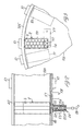
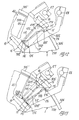
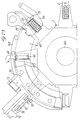
- a cigarette packing machine comprises a conveyor drum 1, known as a forming wheel, which is supported rotatably about its own axis on a shaft 301 from which it projects.
- the forming wheel 1 has a plurality of peripheral radial compartments 101, each of which houses a group of cigarettes S together with a wrapping slip 2 for the said group of cigarettes.
- the compartments 101 are distributed at equal angular intervals around the circumference of the forming wheel 1 which is made to rotate in steps whose angular size is equal to the angular distance between the individual compartments 101.
- a pusher/follower group indicated as a whole by the number 3, which has an expelling pusher 103 and a follower 203 on diametrically opposite sides.
- the expelling pusher 103 and the follower 203 can be made to slide in diametrically opposite directions to each other and interact with the group of cigarettes S together with the slip 2 in the feed station A and with the group of cigarettes wrapped in the wrapping slip 2 in the expulsion station E on the diametrically opposite side.
- the group of cigarettes S has a predetermined number of cigarettes into an ordered arrangement identical to that which the cigarettes are designed to have in the packaged state.
- the group of cigarettes S is orientated with the axes of the cigarettes parallel to the axis of the forming wheel 1, while the ends of the cigarettes are disposed substantially flush with the outer sides of the discs 201.
- the group of cigarettes is formed by the feeding of a specified number of cigarettes into compartments of predetermined shape associated with a conveyor belt, known as a box conveyor, which is not illustrated and is known. Each group of cigarettes is then conveyed to a transfer station and then to a station for combination with a wrapping slip.
- the group of cigarettes is disposed to coincide with the complementary compartment 101, in front of the open entry side of the compartment, in such a way that it can be introduced into the compartment by a movement in a direction which is transverse with respect to the cigarettes and radial with respect to the forming wheel 1.
- a wrapping slip 2 is fed to the transverse side of the group of cigarettes S, while the slip and the group of cigarettes are held in position and then transferred together into the compartment 101 by a feed pusher 4 which interacts with the follower 203 and can be moved together with it.
- the wrapping slip is automatically folded around the sides of the group of cigarettes S inside the compartment 101, while its axial flaps 102, 202 project radially from the entry aperture of the said compartment 101.
- the folding of the wrapping slip 2 around the ordered group of cigarettes at the time of insertion into the compartment 101 is caused by two opposite folding edges 105, 205 of a stationary aperture 5 which is provided in a position coinciding with the open side of the compartment 101 in the feed station A, and which is made in a stationary cylindrical coaxial peripheral wall 305 which extends around the forming wheel 1.
- a tangential folder 6 is supported so that it can be moved parallel to its extension and alternately in each direction, in other words in the direction of advance of the forming wheel 1 and in the opposite direction, substantially along a path tangential to the forming wheel 1, or to the open side of the compartment 101 in the feed station A.
- the folder is mounted on the upper end of an arm 106 which forms part of a hinged system of levers 206, 306, 406.
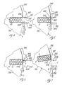
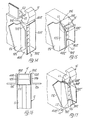
- Figs. 4 to 7 show the phases of folding the flaps 102, 202 of the wrapping sheet 2 for the formation of a tubular wrapping which is open at the ends and whose axis is parallel to the axes of the cigarettes S and to the axis of the forming wheel.
- the lengths of the two flaps 102, 202 are such that, when folded onto the side of the group of cigarettes coinciding with the open side of the compartment 101, they overlap each other by a certain amount.
- the flaps 102, 202 extend along two horizontal radial walls 405, 505 which are aligned flush with the folding edges 105, 205 of the aperture 5.
- the tangential folder 6 starts the folding travel, by which it moves in the direction of advance of the forming wheel 1 and substantially tangentially to the said wheel (Fig. 5).
- the flap 202 is consequently folded onto the corresponding side of the group of cigarettes S.
- the forming wheel 1 undergoes the step of advance with a predetermined delay with respect to the advance travel of the tangential folder 6.
- This delay and the two speeds of advance of the forming wheel 1 and of the folder 6 are set in such a way that the folder 6 completes its travel with respect to the flap 202 of the wrapping slip 2 in a position such that the front edge of the folder 6 is withdrawn through a certain distance from the free front edge of the flap 202, forming a free front strip 302.
- the folding edge 605 of the said flap 102 brings this flap into a position in which it partially overlaps the rear flap 202, on the strip 302.
- the folder 6 is made to approach the folding edge 605 of the front flap 102.
- the extension of the front overlap strip 302 in the direction of advance of the forming wheel 1 and the folding travel of the folder 6 in the direction of advance of the forming wheel 1 are such that the tangential folder 6 reverses its travel at a predetermined minimum distance from the folding edge 605 of the front flap 102.
- the front overlap strip 302 of the rear flap 202 has penetrated beneath the folding edge 605, which has overlapped onto it, by folding, a partial initial portion of the front flap 102.
- the folded rear flap 202 is kept in position by the front flap 102 which is partially overlapped onto it and the folder 6 can depart completely from the position of folding the associated rear flap 202, moving into the withdrawn start position for a new folding travel.
- the advance of the forming wheel 1 causes the completion of the folding of the front flap 102 onto the corresponding side of the group of cigarettes.
- the flap 102 which is in a position overlapping all the remaining flaps, is kept in the said folded position by the cylindrical surface of the wall 305.
- folding means are provided to close the open ends of the tubular wrapping which was formed in the feed station A and completed in the initial part of the step of advance of the compartment 101.
- the tubular wrapping formed by the slip 2 projects beyond the ends of the cigarettes which are aligned with each other with tubular end portions which form opposite pairs of wings orientated in the radial direction 402, 502 and in the tangential direction 602, 702 with respect to the forming wheel 1, these wings being connected together at the axial contact edges.
- a pair of blocks 15 for folding the radially inner tangential wing 602 and the radially outer tangential wing 702 is provided on each side of the forming wheel 1 at the folding station P.
- the folding blocks 15 are disposed outside the corresponding wings 602, 702, and each has a folding surface 115 terminating in a free edge substantially coinciding with or directly adjacent to the folding line L1 of the corresponding wing 602, 702 which coincides with the edge of the corresponding side of the group of cigarettes.
- the said free edge may advantageously consist of a sharp edge 215 of the folding block 15, while the surface 115 in the rest position is disposed so that it diverges, in the radial direction with respect to the forming wheel 1, from the wing 602, 702.
- each folding block 15 can swing about an axis O which coincides with the edge 215.
- each folding block 15 is supported by a bar 16 which is parallel to the axis of oscillation O of the folding blocks 15.
- One end of each bar 16 is fixed to the end of a radial arm 17 which rotates integrally with a shaft 18.
- the folding block 15 is fixed to the opposite end of the bar 16 and projects in such a way that the connecting line between the axis of the bar 16 and the edge 215 is axially aligned with the radial arm 17, while the edge 215 is made to coincide with the extension of the axis O of the shaft 18.
- the shafts 18 are supported freely rotatably in a wall 119 of a box 19, and their inner ends are mechanically connected to synchronized drive means.
- a pair of opposing folding blades 25, 26 is provided on each side of the forming wheel 1 to fold the radial wings 402, 502 of the ends of the tubular wrapping projecting beyond the ends of the cigarettes S.
- the folding blades extend parallel and tangentially to the plane containing the ends of the cigarettes, and can be swung parallel to each other in the said tangential plane alternately in the direction of advance of the forming wheel 1 and in the opposite direction along a path forming a secant of the forming wheel 1.
- the folding blades 25, 26 have transverse extensions 125, 126 on the sides facing the corresponding radial wings 402, 502.
- the path of oscillation of the said folding blades 25, 26 is such that, during the phase in which the compartment 101 is stationary in the folding station P, they can move into a stand-by position (Fig. 9) in which they are swung into a position where the extensions 125, 126 are aligned with the outer surfaces of the corresponding sides of the tubular wrapping, and where they contact the associated wings 402, 502, thus forming containment surfaces for the said wings 402, 502, substantially as axial extensions of the corresponding radial walls of the compartments 101.
- Each blade 25, 26 is supported on and projects from an arm 225, 226.
- Each arm 225, 226 is fixed at its end to an associated drive shaft 27, 28 and rotates integrally with it.
- Each drive shaft 27, 28 carries the two corresponding folding blades 25, 26 on the two opposite sides of the forming wheel 1.
- the cylindrical peripheral wall 305 which surrounds the forming wheel 1 has an aperture, or rather an interruption, 805 at the folding station P.
- a retaining plate 33 supported so that it can alternately approach and withdraw from the said side of the group of cigarettes wrapped in the tubular wrapping, is therefore provided to keep the flaps 102, 202 on the radially outer side of the tubular wrapping in the folded position without interfering with the folding blocks 15.
- the retaining plate 33 is slightly shorter than the axial extension of the corresponding side of the group of cigarettes S.
- the retaining plate 33 is supported at the end of a radial arm 134 of a system of hinged levers 34.
- the operation of the folding blocks 15, the folding blades 25, 26 and the retaining plate 33 in synchronization with the steps of advance of the forming wheel 1 and with each other is provided by taking the motive power from a common motor or a common power take-off which may advantageously be the power take-off for the forming wheel.
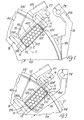
- Figures 8 to 18 show some phases of the folding of the radial and tangential wings 402, 502, 602, 702 which form the end portions of the tubular wrapping projecting beyond the ends of the group of cigarettes.
- the compartment 101 coincides with the aperture 805 in the peripheral cylindrical wall 305 and the retaining plate 33 is brought next to the folded and overlapped axial flaps 102, 202 of the wrapping slip 2 to keep them in position.
- the front folding blades 25 are in the rest position, in which their extensions 125 and the folding edge are aligned with the corresponding front radial wall of the compartment 101, so that the front radial wings 402 are made to bear on the extensions 125 of the blades 25.
- the blocks 15 are in the rest position, with the edge 215 of the folding surface 115 disposed on the folding line L1 of the said tangential wings 602, 702, while the folding surface 115 diverges from the said wings 602, 702.
- the rear folding blades 26 are then swung in the direction of advance of the forming wheel into a stand-by position in which they are disposed in alignment, similarly to the facing front folding blades 25, with the corresponding radial side of the compartment 101.
- the blocks 15 are then (Figs.
- each radial side 402' and 502' is in the shape of an isosceles triangle whose longer base coincides with its folding line L2 i.e. is tangential or coincides with the radial edge of the end of the group of cigarettes S.
- the folding blocks 15 are then (see Figs. 11 and 17) swung again into the rest position, while the front folding blade 25 is operated and, with an angular movement tangential to the end of the group of cigarettes and in a direction opposite to the direction of advance of the wheel, causes the front radial flap 402' to be folded onto the end of the group of cigarettes and in a condition in which they overlap the previously folded tangential wings 602 and 702.
- the whole takes place at a speed which is higher than that of the elastic return of the tangential wings to their unfolded or partially folded condition and is sufficient to prevent them from assuming a position which adversely affects the correct folding of the slip on the ends of the group of cigarettes.
- At least the perpendicular extension 125 of the front folding blade 25 has a trapezoidal shape, substantially identical to the trapezoidal shape of the radial flaps 402', 502'. This enables the wait time of the operation of the folding blade 5 to be reduced, since it can start with a certain advance, while the folding blocks 15 have completed only part of the return travel and are in a position of intermediate elevation in which the angle between the folding surface 115 and the end of the group of cigarettes is slightly greater than the angle between the inclined sides and the base of the trapezoidal extension 125 of the folding blade 25. The latter may therefore be inserted under the folding blocks 15 when they are still at an intermediate point of the return travel.
- the rear folding blade 26 is operated before the start of the return travel of the front folding blade 25, and is swung in the direction of advance of the forming wheel 1 towards the front folding blade 25 up to a certain distance from it. When this minimum approach distance is reached, the front folding blade 25 starts the return travel at a speed substantially equal to that of the rear folding blade 26.
- the folding travel of the rear blade 26 and the return travel of the front blade 25, as well as the path of the facing folding edges of the said folding blades 25, 26 and the minimum distance between these, are set in such a way that in the terminal parts of the folding and return travels the rear folding blade 26 is superimposed, directly or with the interposition of the rear radial flap 502, at least partially on the front radial flap 402, while the front blade 25 is still superimposed on the front edge of the end of the group of cigarettes (Fig. 12).
- the forming wheel undergoes the step of advance, while the two folding blades 25, 26 end their simultaneous travel in the direction of advance of the forming wheel, with a certain delay with respect to the execution of the step of advance and at a speed lower than that of the step of advance of the compartments 101 (Fig. 13).
- the group of cigarettes is therefore moved relative to the folding blades 25, 26 in the direction of advance of the wheel 1. The whole is adjusted and designed in such a way that, as shown in Fig.
- the end of the outer rear radial wing 502' which is free and turned in the direction of advance of the forming wheel 1 is inserted in a pleated state under the folding edge of the front folding blade 25, while the rear blade 26 is still partially superimposed on an area on the opposite side of the said outer rear radial wing 502'.
- the folding edge of the folding blade 25 has a chamfered or rounded guide area 225 for this purpose.
- the forming wheel 1 is associated with an extension of the peripheral coaxial cylindrical wall 305' to keep the axial flaps 102, 202 in the folded condition, together with a sliding surface 140 of a lateral wall 40 on each side of the forming wheel 1, to keep the wings 402, 502, 602, 702 in the folded condition on the ends of the group of cigarettes, along which surfaces the outer rear wings 502' of the end of the packaged group of cigarettes slide in a pleated condition (see Fig. 18).
- the front folding blades 25 and the leading portions, facing these blades, of the lateral walls 40 forming the surfaces 140 have complementary recesses or taperings for mutual engagement 425, 240 on the sides facing each other.
- the whole is made in such a way that, in the position of the end of travel in the direction of advance of the forming wheel 1, the folding blades 25 are engaged with the walls 40, whose inner surfaces are substantially flush with the inner surfaces of the portions 525 of the blades 25 on the side of the folding edge.
- the folding process as described above, and consisting in the operation in rapid succession of the folding means 6, 605, 15, 25, 26 at a speed markedly higher than that of the recovery, in other words the elastic return, of the folding flaps or wings 102, 202, 402, 502, 602, 702 in the folded position or in an intermediate folding position, is not applicable to all wrapping materials.
- the operating speeds required, in particular for the operation of the folding blocks 15 and the front folding blade 25, may become excessively high.
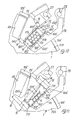
- the invention includes a variant shown in Figs. 19 to 22.
- the edge 215 of the folding block 15 about which the block 15 oscillates does not have a length substantially identical to the side and to the tangential wing 602, 702, as in the preceding example shown in Figs. 8 to 18; instead, the edge 215' and consequently the blocks 15' are made shorter than the corresponding tangential wings 602, 702 on the side facing the front folding blade 25, and leave free a strip 902 on which part of the radial wing 402 can be overlapped before the start of the return travel of the blocks 15. This is done by means of the operation of the front folding blade 25 for the execution of the folding travel with a certain predetermined advance with respect to the start of the return travel of the folding blocks 15.
- peripheral strip 902 and the advance, as well as the speed of advance of the blocks 15' and the front folding blade 25 are such that when it is overlapped by a sufficient amount to keep the tangential wings 602, 702 temporarily in the folded position and at a predetermined minimum distance from the blocks 15 (Fig. 20), these blocks start their return travel to the rest position at a speed such that interference with the folding blade 25 is avoided.
- the forming wheel 1 is associated with means of welding the flaps 102, 202 and the wings 402, 502, 602, 702 of the wrapping slip 2 which have been folded and overlapped on each other on the corresponding sides of the group of cigarettes S.
- the welding means may be of any type. They may consist of welding heads which are provided at a station following the folding station of the corresponding flaps or corresponding wings 102, 202, 402, 502, 602, 702, and which are supported so that they can be moved alternately into the active welding position against the corresponding sides of the group of cigarettes, on which the said flaps and said wings are folded, through apertures made in the walls 305, 305', 40.
- a solution of this type is known and is commonly used in cellophane wrapping machines.
- a welding unit of this type may be formed, for example, by the retaining plate 33 which may carry on its rear face a suitable heater 50 which brings it to, and keeps it at, the welding temperature.
- the welding means may also consist of the walls 305, 305' and 40, against which slide the sides of the group of cigarettes on which the flaps or wings 102, 202, 402, 502, 602, 702 are folded and overlapped on each other.
- This type of welder is also known and used in the field of cellophane wrapping machines.
- heating means 51 which are distributed suitably over the extension of the walls 305, 305', 40 and which bring the said walls or predetermined parts of them to the welding temperature.
- the flaps and wings 102, 202, 402, 502, 602, 702 are welded together during their sliding on the said heated walls.
- the welding of the flaps or wings 102, 202, 402, 502, 602, 702 may take place immediately after each individual phase of folding of the flaps or wings on the corresponding side, or when the wrapping slip has been completely folded around the group of cigarettes in the path after the folding station P.
- the wrapping slip 2 may be made of various types of plastic material. Some types may consist of thermoplastic and heat-weldable resins currently in use particularly in the field of packaging, for example polypropylene, polyvinyl butyral, known as PVB, ethylene vinyl acetate, known as EVA, or ionomeric resins.
- a vacuum or a low pressure may be created inside the package formed by the wrapping sheet folded around the group of cigarettes and welded.
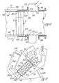
- Figures 2 and 3 show schematically and purely by way of example means for creating the vacuum or low pressure, consisting of a needle 52 which is heated 53, this needle being orientated with its axis parallel to the axes of the cigarettes S and coinciding with a free space among the cigarettes S.
- the suction needle 52 is movable axially alternately between a position in which it is withdrawn from the group of cigarettes and a position in which it penetrates into the empty space among the cigarettes S through a perforation of the corresponding side of the wrapping sheet 2.
- the needle 52 is pushed by a piston 154 of an actuating cylinder 54 into the penetration position, and is returned to the withdrawn position by an elastic opposing element 55.
- the rod of the piston 154 is tubular and forms the union for connection to the suction line 56.
- the plastic materials used enable the hole to be closed by the fluidity of the material after the extraction of the heated needle 52.
- means may also be provided for the closure of the hole made by the suction needle 52, such as an oscillating blade 57 with a drive unit 58.
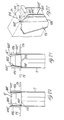
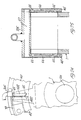
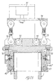
- Figs. 23 to 26 show a variant embodiment of the welding devices and the means for suction, to create a low pressure inside the wrapping, and/or injection, to introduce a certain amount of humid air or gas into the wrapping.
- the welder of the axial flaps 102, 202 of the wrapping 2 on the radially outer side of the tubular wrapping still comprises the retaining plate 33 with the associated heating means 50.
- the plate 33 has a trapezoidal section and the heating means are inserted in a particular housing, for example a hole, a recess, or similar, which are made inside the plate 33.
- the folding of the wings 402, 502, 602, 702 onto the ends of the wrapping is executed in a way which is substantially the same as the one described above.
- the radial wing 402 that is the front wing with respect to the rotation of the forming wheel, can be folded last, onto the radial rear wing 502.
- the lateral wall 40 along which the ends of the wrapping slide, during the steps of advance of the wheel, into the stations following the station for folding the flaps 402, 502, 602, 702, is composed of two separate portions, indicated in figure 23 as 40' and 40''.
- the first portion 40' is stationary and extends from the folding and side welding station of the end flaps 402, 502, 602, 702, to a subsequent station of suction and/or injection of air or gas from or into the wrapping.
- the end of the lateral wall 40' is slightly withdrawn from the radial, axial, frontal side of the wrapping which is already between the two moving walls 40'', the latter being the welding means for the ends of the wrapping and the extensions of the stationary lateral walls 40'.
- suction and/or injection slot-like outlets 65 orientated so as to be substantialy tangential with respect to the circular path of the groups of cigarettes wrapped in the wrapping 2.
- the suction and/or injection outlets 65 are provided in a coinciding position on both the facing lateral walls 40' and are connected by means of radial feed lines 66, to a common manifold 67 whose position is axial and radially outside the wheel inside a peripheral tunnel 305.
- the peripheral tunnel can also house further heating means 50.
- the manifold 67 communicates through connecting tubing 66 with a source providing low pressure, or feeding air or gas containing a predetermined amount of humidity.
- the extensions of the stationary lateral walls 40' are the moving lateral walls 40'', which are particularly oscillating between an idle position in which they oscillate outwards and keep a distance from the ends of the wrapping, and an operated position, in which they adhere to the said ends and extend flushing with the inner surfaces of the stationary lateral walls 40', in a complanar way.
- the oscillating lateral walls 40'' are provided with heating means 51 and are supported by oscillating L- shaped wings 70, which have a branch parallel to the oscillating lateral walls 40'' and a branch transverse to them, that is orientated axially with respect to the wheel.
- the oscillating wings are arched coaxially with respect to the forming wheel and are hinged in 71, 72 in at least one point, preferably two points, around a tangential axis. In a position excentric with respect to the hinging axis, that is more exterior with reference to the transverse median plane of the forming wheel, the oscillating wings are hinged each to an operating arm 73.
- the arms 73 are hinged to an axial crosspiece 74, which is fixed to a linear actuator 75, for example pneumatic, hydraulic, electrical, or similar, whose moving sense or direction is orientated radially with respect to the wheel.
- the travel of the linear actuator 74 makes the wings 70, and hence the lateral walls 40'', oscillate outwards and against the ends of the cigarettes.
- This is a very advantageous characteristic, as it allows to move the welders away from the wrappings in case of machine stop.
- these welders have a very high heat capacity, and they substantially maintain the temperature of welding for a relatively long period, even when the heating means are off. Therefore, in case of machine stop, the groups of cigarettes wrapped in the wrapping foil which are between the lateral welders can also catch fire or anyway be overheated, thus leading to serious drawbacks and damages.
- the stationary lateral walls 40' and the oscillating lateral walls 40'' have facing radial edges very close to each other, while the suction and/or injection slot-like outlets terminate at a very short distance from the radial edge of the stationary walls 40', this edge facing the oscillating lateral walls 40''.
- the outlets 65 are so wide that, as the forming wheel progressively advances, the edges of the radial wings progressively interact with the moving lateral walls 40'', that is with the welding devices of the ends of the wrapping, with their front portions, while the rear portions, which are nor subject to sealing yet, are still coinciding with the suction and/or injection outlets.
- the suction or feeding of air or gas containing a predetermined amount of humidity by the outlets 65 are kept operating.
- the low pressure or the amount of air or gas containing a predetermined quantity of relative humidity, injected inside the wrapping can be also maintained at the desired levels, by providing a suction at higher vacuum levels than the desired ones or an injection with higher pressure than the final one, so that the losses eventually occurring while the final portions of the edges of the radial refolded wings 402, 502 pass form the suction and/or injection outlets to the welding lateral walls 40'' can be widely compensated.
- the package according to the invention may have predetermined opening means of any type, such as predetermined tear strips, etc.
- the packaging wrapping may also be completely transparent or opaque or partially transparent and may have different colours and designs or similar printed on it.
- the package according to the invention may form the finished package of the cigarettes or an inner package, as is currently done with foil slips in soft packs and rigid packs of cigarettes.
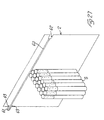
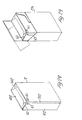
- Figs. 27 to 29 show an example of such a wrapping slip.
- the slip 2 has a predetermined tear strip 60 extending transversely to the axis of the cigarettes S and in such a position, to be substantially at the ends of the filtres of the said cigarettes, that is at their ends on the opening side of the pack.
- the predetermined tear strip extends on one side onto a grasping tongue 61 of the wrapping slip 2, while the opposite end of the said strip ends into a notch 62 of the wrapping slip, whose shape is substantially identical to the tongue.
- the tongue 61 is separated form the slip 2, up to a certain extent, by two notchings parallel to each other and to the direction of the tear strip.
- the predetermined tear strip 60 is provided in such a position that, while the slip 2 is folded around the group of cigarettes, it coincides substantially with the peripheral edge of the end of the wrapping on the opening side of the pack P.
- the tongue 61 whose transverse size is defined by the two notchings 63, which define substantially the border between the tongue itself and the rest of the wrapping, is disposed astride of the said peripheral edge of the end of the wrapping, therefore when tearing the tongue, the edge of the portion of the wrapping slip which remains inside the pack, extends slightly under the ends of the cigarettes, so that they can be easily grasped.
- the wrapping slip can be advantageously, but not by way of restriction, wrapped around the group of cigarettes, in such a relative position that, as figs. 28 and 29 show, the grasping tongue of the predetermined tear strip is situated at one of the frontal edges of the inner wrapping of the pack P. Thanks to this arrangement, when the pack is being open, the tongue can be immediately identified and easily grasped.
- Figs. 23 to 26 show a variant embodiment of the welding means for a heat-weldable wrapping slip,and of the station of air suction and/or injection from or into the package of each group of cigarettes.
Landscapes
- Engineering & Computer Science (AREA)
- Mechanical Engineering (AREA)
- Chemical & Material Sciences (AREA)
- Dispersion Chemistry (AREA)
- Wrapping Of Specific Fragile Articles (AREA)
Description
- the formation and/or feeding of a group of cigarettes in a predetermined number and order corresponding to those of the packaged state;
- the association of the group of cigarettes with a wrapping sheet consisting of a sheet of impermeable, thermoplastic and heat-weldable material in a predetermined relative position, and the insertion of these into a compartment with simultaneous folding of the wrapping sheet in a "C" shape around the sides of the group of cigarettes next to the sealed sides of the compartment ;
- the formation of a tubular wrapping by folding and retaining in position flaps of the wrapping sheet on the side of the group of cigarettes located at the open entry side of the compartment ;
- the subsequent closure of the open ends of the tubular wrapping by the folding of wings formed by the terminal portions at the ends of the tubular wrapping projecting beyond the corresponding sides of the group of cigarettes ;
- the welding by heating to the welding temperature, of the flaps, wings or parts of the wrapping sheet which overlap each other on the various sides of the group of cigarettes.
- it includes a phase of a low pressure inside the package or a phase of injection into the package of a predetermined volume of air or other gas containing a predetermined amount of relative humidity,
- the suction or injection is made through apertures between the overlapping folded wings prior to their sealing, and
- in the suction or injection phase the overlapping wings are sealed together by welding in a progressive way, with respect to their extension, while the portions which have not been welded yet are subject to the operation of suction or injection, the latter not-welded portions being changed very rapidly from the suction phase to the welding phase.
- means for forming an ordered group of cigarettes;
- means for feeding the said group together with a wrapping sheet into a compartment open at least at one entry side and at two sides transverse with respect to the entry side;
- means for transporting the said compartment;
- moving and/or stationary folding means which are distributed along the path of the compartment for the group of cigarettes to be packaged and for the associated wrapping slip, these means being designed to fold the wrapping sheet around the group of cigarettes to form a first tubular wrapping and subsequently to close the said tubular wrapping at its open ends;
- welding means distributed along the path of the compartment, after all the stations or after each station for folding the parts or flaps or wings which overlapp each other on at least one side of the group of cigarettes, said welding means being provided for welding the said parts, flaps or wings together to provide a hermetic seal of the wrapping of the package,
- characterized in that
- it includes means for creating a low pressure or vacuum inside each package or for injecting air or gas containing a predetermined amount of humidity inside each package, with the possibility of operating and stopping these means alternately, and of keeping them operating until the package is at least partially in their station,
- and which suction or injection means comprise pairs of slot-like outlets, whose major axis is orientated in the direction of advance of the packages or tangentially with respect to their path, and which are made in stationary lateral walls which retain in folded and overlapping position the wings on the ends of the packages, the said suction or injection outlets being disposed so that they cooperate for the whole phase in which the packages pass along them with at least part of the radially outer or radially inner edges of the radial refolded wings, preferably at their crossing area, whereas the said lateral walls terminate with a radial edge in a slightly withdrawn position with respect to the frontal side of the package,
- in order to seal together the wings by welding in a progressive way, the welders of the wrapping at the ends of the packages comprise two opposite heated plates, along each of which the ends of the packages slide, and which extend up to a predetermined portion of the path of the packages, said plates being extension of the stationary plates, in which the suction and/or injection outlets are provided, the inner wall of said welding plates extending on the same plane as the stationary plates and said welding plates being partially superimposed on the corresponding end of the packages when the latter are in the suction and/or injection station.
Claims (11)
- Process for the fabrication of a package of cigarettes in which exists either a vacuum or a pressure obtained by means of a gas containing a predetermined amount of steam or humidity, which process comprises the following phases:characterized in thatthe formation and/or feeding of a group of cigarettes (S) in a predetermined number and order corresponding to those of the packaged state;the association of the group of cigarettes with a wrapping sheet (2) consisting of a sheet of impermeable, thermoplastic and/or heat-weldable material in a predetermined relative position, and the insertion of these into a compartment (101) with simultaneous folding of the wrapping sheet (2) in a "C" shape around the sides of the group of cigarettes (S) next to the sealed sides of the compartment (101);the formation of a tubular wrapping by folding and retaining in position flaps (102, 202) of the wrapping sheet (2) on the side of the group of cigarettes (S) located at the open entry side of the compartment (101);the subsequent closure of the open ends of the tubular wrapping by the folding of wings formed by the terminal portions (402, 502, 602, 702) at the ends of the tubular wrapping projecting beyond the corresponding sides of the group of cigarettes (S);the welding (33, 50; 305, 305', 40, 51), by heating to the welding temperature, of the flaps, wings or parts (102, 202, 402, 502, 602, 702) of the wrapping sheet (2) which overlap each other on the various sides of the group of cigarettes (S),it includes a phase of a low pressure inside the package or a phase of injection into the package of a predetermined volume of air or other gas containing a predetermined amount of relative humidity,the suction or injection is made through apertures between the overlapping folded wings (402, 502, 602, 702) prior to their sealing, andin the suction or injection phase the overlapping wings (402, 502, 602, 702) are sealed together by welding in a progressive way, with respect to their extension, while the portions which have not been welded yet are subject to the operation of suction or injection, the latter not-welded portions being changed very rapidly from the suction phase to the welding phase.
- Process according to claim 1, characterized in that, in order to compensate for the eventual loss of low pressure or the partial discharge of the injected humidified air or gas, the low pressure created or the quantity of humidified air, that is its pressure injected, have higher values than the terminal ones.
- Process according to claim 1 or 2, characterized in that it includes further phases of formation of a further outer wrapping of the package, for example by wrapping the group of cigarettes, which have been sealed in the first wrapping, in a second paper wrapping slip, or by folding a punched cardboard blank or similar around the group of cigarettes sealed in the first wrapping slip.
- Process according to one or more of the preceding claims, characterized in that the complete formation of the package, in other words the complete folding of the wrapping sheet (2) around the ordered group of cigarettes (S), is executed in only two stations, namely in a station (A) in which the group of cigarettes (S) and the wrapping slip (2) are fed into the compartment (101) and in only one of the following stations, so-called folding station (P), the package being fully formed on exit from the said folding station (P), and the formation of the open tubular wrapping being carried out substantially in a feed station (A) and completed during the step of advance, more particularly in the initial portion of the step of advance, the closure of the ends of the tubular wrapping being completed simultaneously for the two opposite ends of the tubular wrapping in the folding station (P), while in the first step of advance and in the subsequent step of advance the fully formed wrapping is simply kept closed and subjected to the action of means of welding the parts, flaps or wings (102, 202, 402, 502, 602, 702) overlapping each other on the corresponding sides.
- Process according to one or more of the preceding claims, characterized in that it includes the folding of the wrapping slip (2) for the closure of the open sides in such a way that the flaps or wings (102, 202, 402, 502, 602, 702) are folded in succession so that they overlap each other at least partially (302, 902), from the innermost to the outermost ones, at a speed higher than the speed of elastic return to the substantially unfolded position or to an intermediate position of folding of the said wings or of the said flaps, while the final outer flap or wing is kept in the folded position against the corresponding side of the group of cigarettes and against the other inner flaps or wings until the parts, flaps or wings of each side of the group of cigarettes, wrapped in this way in the wrapping slip, are sealed together by welding.
- Process according to one or more of the preceding claims, characterized in that it provides for leaving free on the inner flaps or wings (202, 402, 602, 702) at least one peripheral strip (302, 902) to be overlapped by an outer flap or wing (102, 501), this peripheral overlap strip (302, 902) being provided on a side directly adjacent, next to or facing the subsequent outer flap or wing (102, 502), or a part of the flap or wing which is folded into position first, the inner wing or flap being retained in the folded position only until the outer folding wing or flap at least partially overlaps the free overlap strip, while when all the parts or flaps (102, 202, 402, 502, 602, 702) have been folded and overlapped on each other on the corresponding side they are sealed by welding.
- Device for the application of the process according to one or more of the preceding claims comprising:means for forming an ordered group of cigarettes;means (4, 203) for feeding the said group together with a wrapping sheet (2) into a compartment (101) open at least at one entry side and at two sides transverse with respect to the entry side;means (1, 201) for transporting the said compartment (101);moving and/or stationary folding means (5, 105, 205, 6, 605, 15, 115, 25, 26) which are distributed along the path of the compartment (101) for the group of cigarettes to be packaged and for the associated wrapping slip, these means (5, 105, 205, 6, 605, 15, 115, 25, 26) being designed to fold the wrapping sheet (2) around the group of cigarettes to form a first tubular wrapping and subsequently to close the said tubular wrapping at its open ends;welding means distributed along the path of the compartment, after all the stations or after each station for folding the parts or flaps or wings which overlapp each other on at least one side of the group of cigarettes, said welding means being provided for welding the said parts, flaps or wings together to provide a hermetic seal of the wrapping of the package, characterized in that it includes means (52, 53, 54, 55, 56, 57, 58, 40', 65, 66, 67) for creating a low pressure or vacuum inside each package or for injecting air or gas containing a predetermined amount of humidity inside each package, with the possibility of operating and stopping these means alternately, and of keeping them operating until the package is at least partially in their station, and which suction or injection means (65) comprise pairs of slot-like outlets (65), whose major axis is orientated in the direction of advance of the packages or tangentially with respect to their path, and which are made in stationary lateral walls (40') which retain in folded and overlapping position the wings (402, 502, 602, 702) on the ends of the packages, the said suction or injection outlets being disposed so that they cooperate for the whole phase in which the packages pass along them, with at least part of the radially outer or radially inner edges of the radial refolded wings (402, 502), preferably at their crossing area, whereas the said lateral walls terminate with a radial edge in a slightly withdrawn position with respect to the frontal side of the package,in order to seal together the wings (402, 502, 602, 702) by welding in a progressive way, the welders of the wrapping at the ends of the packages comprise two opposite heated plates (40'') along each of which the ends of the packages slide, and which extend up to a predetermined portion of the path of the packages, said plates (40'') being the extension of the stationary plates (40'), in which the suction and/or injection outlets (65) are provided, the inner wall of said welding plates (40'') extending on the same plane as the stationary plates (40') and said welding plates (40') being partially superimposed on the corresponding ends of the packages when the latter are in the suction and/or injection station.
- Device according to claim 7, characterized in that the facing ends of the welding plates (40'') and of the stationary plates (40') associated to the suction and/or injecion outlets (65) are disposed directly side-by-side, whereas the suction outlets (65) terminate at a very short distance form the terminal edge of the associated stationary plates (40') or are open up to this point.
- Device according to one of the claims 7 or 8, characterized in that the welding plates (40'') are mounted so as to be movable (70, 71, 72, 73, 74, 75), perfectly oscillating, alternately between an operating position in which they adhere to the ends of the packages to be welded, and an idle position, in which they are moved away form the plane of contact with the said ends of the packages.
- Device according to one or more of the Claims 7 to 9, characterized in that the moving and/or stationary folding means (5, 105, 205, 6, 605, 15, 115, 25, 26) are provided only in the feed station (A) and in only one of the subsequent stations (P), namely in a folding station for the completion of the wrapping of the package.
- Device according to one or more of the claims 7 to 10, characterized in that the folding means (5, 105, 205, 6, 605, 15, 115, 25, 26) are made in such a shape with respect to the flaps or wings (102, 202, 402, 502, 602, 702) and/or are operated in such a way that they terminate or stop at a certain distance from a free edge of the said flaps or the said wings (202, 402, 602, 702), leaving free a partial or complete strip (302, 902) for the overlapping of the next flap or the next wing (102, 402, 502), on the side which is reached first by the folder (605, 25, 26) of the said next wing or the said next flap (102, 402, 502), the folding means (5, 105, 205, 6, 605, 15, 115, 25, 26) and the operating and synchronizing means being made in such a way that the folding means (6, 15, 25) of the inner wings or flaps (202, 402, 602, 702) and those (605, 25, 26) of the wings or flaps (102, 402, 502) directly outside them do not interfere with each other, while means are provided to advance the start of the folding travel of the folding means (605, 25, 26) of the outer wing or flap (102, 402, 502) with respect to the return travel of the folder (6, 15, 25) of the flap or wing (202, 602, 702, 402) immediately below, this advance corresponding to the travel required for the overlapping of the said outer flap or wing (102, 402, 502) onto the free peripheral strip (302, 902) for the overlapping of the inner flap or wing (202, 402, 602, 702).
Applications Claiming Priority (2)
| Application Number | Priority Date | Filing Date | Title |
|---|---|---|---|
| ITGE950073 | 1995-06-28 | ||
| IT95GE000073A IT1281220B1 (en) | 1995-06-28 | 1995-06-28 | PACKAGING FOR ASTIFORM PRODUCTS, IN PARTICULAR SUCH AS CIGARETTES OR SIMILAR, AS WELL AS METHOD AND DEVICE FOR MANUFACTURING THE SAME |
Publications (2)
| Publication Number | Publication Date |
|---|---|
| EP0751069A1 EP0751069A1 (en) | 1997-01-02 |
| EP0751069B1 true EP0751069B1 (en) | 2002-03-27 |
Family
ID=11354771
Family Applications (1)
| Application Number | Title | Priority Date | Filing Date |
|---|---|---|---|
| EP96108719A Expired - Lifetime EP0751069B1 (en) | 1995-06-28 | 1996-05-31 | Process and device for the fabrication of packages for cylindrical products, particularly cigarettes or similar |
Country Status (4)
| Country | Link |
|---|---|
| US (1) | US5729957A (en) |
| EP (1) | EP0751069B1 (en) |
| DE (1) | DE69620060T2 (en) |
| IT (1) | IT1281220B1 (en) |
Families Citing this family (16)
| Publication number | Priority date | Publication date | Assignee | Title |
|---|---|---|---|---|
| IT1290696B1 (en) * | 1997-02-24 | 1998-12-10 | Gd Spa | METHOD AND MACHINE FOR THE WRAPPING OF PRODUCTS. |
| CA2203597A1 (en) * | 1997-04-24 | 1998-10-24 | Rothmans, Benson & Hedges Inc. | Freshness pack |
| US6018932A (en) * | 1998-01-07 | 2000-02-01 | Premark Feg L.L.C. | Gas exchange apparatus |
| DE10000697A1 (en) * | 2000-01-10 | 2001-07-12 | Focke & Co | Method and device for producing (cigarette) packs |
| CZ20001544A3 (en) * | 2000-04-27 | 2001-12-12 | Milan ©Rámek | Wrapper for tobacco products and packaging method |
| US6692423B2 (en) | 2001-11-29 | 2004-02-17 | Sasib Corporation Of America | Method of sealing a cigarette container |
| DE102004011755A1 (en) * | 2004-03-09 | 2005-09-29 | Hauni Maschinenbau Ag | sealer |
| EP1977975A1 (en) | 2007-04-05 | 2008-10-08 | Philip Morris Products S.A. | Method of producing a sealed bundle of consumer articles |
| ITBO20080327A1 (en) * | 2008-05-26 | 2009-11-27 | Gd Spa | METHOD AND UNITS TO FOLD A SHEET OF PAPERS AROUND A GROUP OF CIGARETTES. |
| CN101391662B (en) * | 2008-11-06 | 2010-04-14 | 上海交通大学 | High-speed Cigarette Roller Aluminum Foil Paper Box Folding and Forming Mechanism |
| DE102009021146A1 (en) * | 2009-05-13 | 2010-11-18 | Focke & Co.(Gmbh & Co. Kg) | Method and device for producing (cigarette) packages |
| US8118161B2 (en) | 2009-08-20 | 2012-02-21 | R.J. Reynolds Tobacco Company | Pressurized cigarette packages and methods |
| PL2895395T3 (en) * | 2012-09-04 | 2017-06-30 | Frederik Bergwerff | Method for packaging finished tobacco goods in a master box |
| ITBO20120704A1 (en) * | 2012-12-21 | 2014-06-22 | Mario Spatafora | METHOD AND EQUIPMENT FOR PACKAGING ARTICLES |
| GB201409459D0 (en) * | 2014-05-28 | 2014-07-09 | British American Tobacco Co | Smoking article pack |
| JP6873107B2 (en) * | 2015-09-18 | 2021-05-26 | プリマパック・エルエルシー | Equipment and methods for making flexible packaging |
Family Cites Families (8)
| Publication number | Priority date | Publication date | Assignee | Title |
|---|---|---|---|---|
| US2720738A (en) * | 1954-07-26 | 1955-10-18 | Stephano Brothers | Package wrapping machine |
| US3857221A (en) * | 1973-11-27 | 1974-12-31 | A Schmermund | Folding device for packaging material |
| IT1060149B (en) * | 1976-03-31 | 1982-07-10 | Gd Spa | PERFECTED DEVICE FOR THE REALIZATION OF THE INTERNAL WRAP OF TIN PAPER WITH OVERLAPPING OF THE LONGITUDINAL ENDS OF THE SPEZZON ON ONE OF THE MAJOR FACES OF THE CIGARETTE GROUP IN THE CIGARETTE MACHINE CONDITIONING MACHINES IN STUFFLED MULTI-STUFFED MULTI-STUFFED MULTI-STUFFED MULTI-STUFFED MULTIWOOD |
| DE2740266C2 (en) * | 1977-09-07 | 1983-06-01 | Focke & Pfuhl, 3090 Verden | Device for wrapping objects in a blank |
| DE3123496A1 (en) * | 1981-06-13 | 1983-01-13 | Focke & Co, 2810 Verden | DEVICE FOR PRODUCING PACKS, IN PARTICULAR CIGARETTE RODS |
| IT1207733B (en) * | 1987-06-23 | 1989-05-25 | Gd Spa | METHOD FOR THE PRODUCTION OF CIGARETTE PACKAGES EQUIPPED WITH A HERMETICALLY SEALED ENVELOPE |
| IT1225373B (en) * | 1988-12-21 | 1990-11-13 | Sasib Spa | WRAPPING DEVICE, IN PARTICULAR FOR CIGARETTE PACKAGES, OR SIMILAR |
| IT1241865B (en) * | 1990-06-29 | 1994-02-01 | Sasib Spa | MACHINE FOR WRAPPING PACKAGES OF CIGARETTES OR SIMILAR WITH WRAPPING MATERIAL. |
-
1995
- 1995-06-28 IT IT95GE000073A patent/IT1281220B1/en active IP Right Grant
-
1996
- 1996-05-31 DE DE69620060T patent/DE69620060T2/en not_active Expired - Fee Related
- 1996-05-31 EP EP96108719A patent/EP0751069B1/en not_active Expired - Lifetime
- 1996-06-12 US US08/661,999 patent/US5729957A/en not_active Expired - Fee Related
Also Published As
| Publication number | Publication date |
|---|---|
| EP0751069A1 (en) | 1997-01-02 |
| ITGE950073A1 (en) | 1996-12-28 |
| DE69620060T2 (en) | 2002-11-21 |
| DE69620060D1 (en) | 2002-05-02 |
| ITGE950073A0 (en) | 1995-06-28 |
| IT1281220B1 (en) | 1998-02-17 |
| US5729957A (en) | 1998-03-24 |
Similar Documents
| Publication | Publication Date | Title |
|---|---|---|
| EP0751069B1 (en) | Process and device for the fabrication of packages for cylindrical products, particularly cigarettes or similar | |
| CA1227414A (en) | Method and apparatus for wrapping cigarette packets in film blanks | |
| US4887408A (en) | Method of manufacturing packs of cigarettes with a hermetically sealed wrapper | |
| EP4496747B1 (en) | Wrapping unit and method to produce two sealed wraps, together, by simultaneously folding two wrapping sheets around two corresponding groups of smoking articles | |
| EP1012040B1 (en) | Article wrapping apparatus | |
| EP4257496B1 (en) | Wrapping unit and method to produce a sealed wrap around a group of smoking articles | |
| US4909020A (en) | Process and apparatus for wrapping, especially cigarette packs | |
| CS207388B2 (en) | Facility for packing the cigarettes in the inner foil cover in the high-speed packing machines | |
| GB2242665A (en) | Wrapping packets | |
| US4144695A (en) | Device for folding the head portions of inner wrappers in a machine for packeting cigarettes into hinged-lid type packets | |
| EP3070006B1 (en) | Wrapping method and packer machine to fold a wrapper around a group of tobacco articles | |
| GB1571072A (en) | Cigarette packeting machine | |
| US1964411A (en) | Cigar "cellophaning" machine | |
| EP3628604B1 (en) | Coupling method and unit to couple an insert and a wrapping sheet to a group of smoking articles in a packaging machine | |
| US5718103A (en) | Process and device for packaging products, particularly cylindrical products such as cigarettes, or the like, in a wrapping sheet | |
| EP0792807B1 (en) | Method and unit for folding packing blanks along preformed bend lines | |
| EP4043350B1 (en) | Packer machine and wrapping method to produce a rigid pack for smoking articles with a sealed inner wrap | |
| EP1531127B1 (en) | Method and device for producing a tubular wrapping | |
| JPH02109810A (en) | Rectangular pack and manufacture thereof | |
| EP1688352B1 (en) | Machine for packaging smoking articles | |
| EP4717613A1 (en) | Packer machine and wrapping method for producing a rigid pack for smoking articles with a hinged lid | |
| US3435585A (en) | Apparatus for packing and wrapping | |
| EP4574691A1 (en) | Packer machine and wrapping method to produce a pack for smoking articles | |
| JPH08217005A (en) | Flap-holding device in body-folding device for packaging machine | |
| WO2001015975A2 (en) | System and method for wrapping articles |
Legal Events
| Date | Code | Title | Description |
|---|---|---|---|
| PUAI | Public reference made under article 153(3) epc to a published international application that has entered the european phase |
Free format text: ORIGINAL CODE: 0009012 |
|
| AK | Designated contracting states |
Kind code of ref document: A1 Designated state(s): DE FR GB IT |
|
| 17P | Request for examination filed |
Effective date: 19970606 |
|
| RAP1 | Party data changed (applicant data changed or rights of an application transferred) |
Owner name: SASIB TOBACCO S.P.A. |
|
| 17Q | First examination report despatched |
Effective date: 20000218 |
|
| GRAG | Despatch of communication of intention to grant |
Free format text: ORIGINAL CODE: EPIDOS AGRA |
|
| RTI1 | Title (correction) |
Free format text: PROCESS AND DEVICE FOR THE FABRICATION OF PACKAGES FOR CYLINDRICAL PRODUCTS, PARTICULARLY CIGARETTES OR SIMILAR |
|
| GRAG | Despatch of communication of intention to grant |
Free format text: ORIGINAL CODE: EPIDOS AGRA |
|
| GRAH | Despatch of communication of intention to grant a patent |
Free format text: ORIGINAL CODE: EPIDOS IGRA |
|
| GRAH | Despatch of communication of intention to grant a patent |
Free format text: ORIGINAL CODE: EPIDOS IGRA |
|
| REG | Reference to a national code |
Ref country code: GB Ref legal event code: IF02 |
|
| GRAA | (expected) grant |
Free format text: ORIGINAL CODE: 0009210 |
|
| AK | Designated contracting states |
Kind code of ref document: B1 Designated state(s): DE FR GB IT |
|
| REF | Corresponds to: |
Ref document number: 69620060 Country of ref document: DE Date of ref document: 20020502 |
|
| EN | Fr: translation not filed | ||
| PG25 | Lapsed in a contracting state [announced via postgrant information from national office to epo] |
Ref country code: FR Free format text: LAPSE BECAUSE OF FAILURE TO SUBMIT A TRANSLATION OF THE DESCRIPTION OR TO PAY THE FEE WITHIN THE PRESCRIBED TIME-LIMIT Effective date: 20030103 |
|
| REG | Reference to a national code |
Ref country code: FR Ref legal event code: RN |
|
| PLBE | No opposition filed within time limit |
Free format text: ORIGINAL CODE: 0009261 |
|
| STAA | Information on the status of an ep patent application or granted ep patent |
Free format text: STATUS: NO OPPOSITION FILED WITHIN TIME LIMIT |
|
| 26N | No opposition filed |
Effective date: 20021230 |
|
| REG | Reference to a national code |
Ref country code: FR Ref legal event code: FC |
|
| ET | Fr: translation filed | ||
| PGFP | Annual fee paid to national office [announced via postgrant information from national office to epo] |
Ref country code: GB Payment date: 20040521 Year of fee payment: 9 Ref country code: FR Payment date: 20040521 Year of fee payment: 9 |
|
| PGFP | Annual fee paid to national office [announced via postgrant information from national office to epo] |
Ref country code: DE Payment date: 20040708 Year of fee payment: 9 |
|
| PG25 | Lapsed in a contracting state [announced via postgrant information from national office to epo] |
Ref country code: IT Free format text: LAPSE BECAUSE OF NON-PAYMENT OF DUE FEES Effective date: 20050531 Ref country code: GB Free format text: LAPSE BECAUSE OF NON-PAYMENT OF DUE FEES Effective date: 20050531 |
|
| PG25 | Lapsed in a contracting state [announced via postgrant information from national office to epo] |
Ref country code: DE Free format text: LAPSE BECAUSE OF NON-PAYMENT OF DUE FEES Effective date: 20051201 |
|
| GBPC | Gb: european patent ceased through non-payment of renewal fee |
Effective date: 20050531 |
|
| REG | Reference to a national code |
Ref country code: FR Ref legal event code: ST Effective date: 20060131 |