EP4574627A1 - Steering column for road vehicles - Google Patents
Steering column for road vehicles Download PDFInfo
- Publication number
- EP4574627A1 EP4574627A1 EP24221752.9A EP24221752A EP4574627A1 EP 4574627 A1 EP4574627 A1 EP 4574627A1 EP 24221752 A EP24221752 A EP 24221752A EP 4574627 A1 EP4574627 A1 EP 4574627A1
- Authority
- EP
- European Patent Office
- Prior art keywords
- sleeves
- steering column
- sleeve
- column according
- steering
- Prior art date
- Legal status (The legal status is an assumption and is not a legal conclusion. Google has not performed a legal analysis and makes no representation as to the accuracy of the status listed.)
- Pending
Links
Images


Classifications
-
- B—PERFORMING OPERATIONS; TRANSPORTING
- B62—LAND VEHICLES FOR TRAVELLING OTHERWISE THAN ON RAILS
- B62D—MOTOR VEHICLES; TRAILERS
- B62D1/00—Steering controls, i.e. means for initiating a change of direction of the vehicle
- B62D1/02—Steering controls, i.e. means for initiating a change of direction of the vehicle vehicle-mounted
- B62D1/16—Steering columns
- B62D1/18—Steering columns yieldable or adjustable, e.g. tiltable
- B62D1/185—Steering columns yieldable or adjustable, e.g. tiltable adjustable by axial displacement, e.g. telescopically
-
- B—PERFORMING OPERATIONS; TRANSPORTING
- B62—LAND VEHICLES FOR TRAVELLING OTHERWISE THAN ON RAILS
- B62D—MOTOR VEHICLES; TRAILERS
- B62D1/00—Steering controls, i.e. means for initiating a change of direction of the vehicle
- B62D1/02—Steering controls, i.e. means for initiating a change of direction of the vehicle vehicle-mounted
- B62D1/16—Steering columns
- B62D1/18—Steering columns yieldable or adjustable, e.g. tiltable
Definitions
- the present invention relates to a steering column of the type comprising a steering shaft having an upper post; and a transmission shaft, which is housed in the steering shaft, and has an upper segment, which projects out of the upper post, is provided with a steering wheel so as to allow the driver to selectively control a forward moving direction of the vehicle, and is coupled in a rotary and axially sliding manner to the upper post.
- the upper segment of the transmission shaft sliding along the upper post of the steering shaft allows the driver to adjust in an ergonomic manner the position of the steering wheel with respect to a dashboard and to a control panel of the road vehicle.
- the steering column further comprises a gearbox control assembly fixed on the upper segment of the transmission shaft between the control panel and the steering wheel; and a covering device for at least part of the upper post of the steering shaft.
- the covering device comprises a sleeve made of plastic material or fabric extending around the upper post of the steering shaft.
- the known steering columns of the type described above have some drawbacks mainly originating from the fact that the covering device has relatively high dimensions and has a relatively reduced and limited capacity to cover the upper post of the steering shaft.
- the object of the present invention is to provide a steering column for road vehicles which is free from the drawbacks set forth above and which is simple and cost-effective to manufacture.
- the reference numeral 1 indicates, as a whole, a steering column for road vehicles comprising a steering shaft 2, which is configured to be connected to a body (not shown) of a road vehicle (not shown), and comprises, in turn, an upper post 3 projecting inside a passenger compartment (not shown) of the road vehicle (not shown) from a dashboard 4.
- the steering column 1 further comprises a transmission shaft 5 comprising, in turn, an upper segment 6, which extends inside the post 3, is mounted to rotate around a rotation axis 7, and is coupled in a sliding manner to the segment 6 to perform rectilinear movements along the shaft 2.
- the segment 6 projects out of the post 3, carries a steering wheel 8 connected at a free end thereof, and further supports a gearbox control assembly 9 of the known type mounted between the dashboard 4 and the steering wheel 8.
- the steering column 1 is further associated with a control panel 10, which projects upwards from the post 3, and is locked on the shaft 2 by means of a fixing fork 11 mounted below the post 3.
- the assembly defined by the post 3, by the segment 6, by the steering wheel 8, by the gearbox control assembly 9, and by the control panel 10, is coupled in a rotary manner to the dashboard 4 by means of a plurality of ball joints 12 obtained partly on a fastening plate 13 of the fork 11 and partly on the dashboard 4.
- the steering column 1 is further provided with a covering device 14 for an end segment of the post 3.
- the device 14 comprises a first sleeve 15, which extends around the post 3 coaxially to the axis 7, is limited by an annular-shaped bottom wall 16 substantially perpendicular to the axis 7, and is axially locked on the control panel 10 by engaging an annular flange 17 radially projecting outwards from the sleeve 15 into a recess 18 obtained partly on the control panel 10 and partly on the fork 11.
- the sleeve 15 is provided with a plurality of cylindrical guides 19, which are uniformly distributed around the axis 7 and the post 3, and project from the wall 16 parallel to the axis 7.
- the device 14 further comprises a second sleeve 20, which extends around the post 3, and is axially locked on the gearbox control assembly 9 by means of a plurality of fixing screws (not shown).
- the sleeve 20 is limited by an annular-shaped bottom wall 21 substantially perpendicular to the axis 7, and is provided with a plurality of cylindrical guides 22, which are uniformly distributed around the axis 7 and the post 3, project from the wall 16 parallel to the axis 7, and are axially open at the wall 21.
- the device 14 further comprises a third sleeve 23, which extends around the post 3, is limited by an annular-shaped bottom wall 24 substantially perpendicular to the axis 7, and is provided with a plurality of cylindrical guides 25.
- the guides 25 are uniformly distributed around the axis 7 and the post 3, project from the wall 24 parallel to the axis 7, are axially open at the wall 24, and are coupled in a sliding manner to the guides 19 of the sleeve 15.
- the device 14 further comprises a fourth sleeve 26, which extends around the post 3, is limited by an annular-shaped bottom wall 27 substantially perpendicular to the axis 7, and is provided with a plurality of cylindrical guides 28.
- the guides 28 are uniformly distributed around the axis 7 and the post 3, project from the wall 27 parallel to the axis 7, are axially open at the wall 27, and are coupled in a sliding manner to the guides 22 of the sleeve 20 and to the guides 25 of the sleeve 23.
- the guides 19 are equal in number to the number of the guides 22, to the number of the guides 25, and to the number of the guides 28.
- the sleeve 20 has a smaller cross section than the cross section of the sleeve 26 so as to move inside the sleeve 26; the sleeve 26 has a smaller cross section than the cross section of the sleeve 23 so as to move inside the sleeve 23; and the sleeve 23 has a smaller cross section than the cross section of the sleeve 15 so as to move inside the sleeve 15.
- the sleeves 20, 23, 26 are moved by the springs 29, 30, 31 to an extracted position ( Figure 1 ), are movable to a retracted position ( Figure 2 ) against the bias of the springs 29, 30, 31, and are stopped in their extracted position by engaging respective pairs of limit stop flanges 32 obtained at the ends of the guides 19, 22, 25, 28.
- the sleeves 15, 20, 23, 26 are made of a stiff material, in particular a plastic material.
- the steering column 1 has some advantages mainly originating from the fact that the covering device 14 has relatively reduced dimensions and a relatively high capacity to cover the upper post 3 of the shaft 2.
- the covering device 14 has, when arranged in its extracted position, a length, measured between the control panel 10 and the gearbox control assembly 9, at least of 120 mm.
Landscapes
- Engineering & Computer Science (AREA)
- Chemical & Material Sciences (AREA)
- Combustion & Propulsion (AREA)
- Transportation (AREA)
- Mechanical Engineering (AREA)
- Steering Controls (AREA)
- Body Structure For Vehicles (AREA)
Abstract
A steering column for road vehicles having a steering shaft (2); a transmission shaft (5), which is housed in the steering shaft (2), is provided with a steering wheel (8) and has an upper segment (6), which projects out of, and is coupled in a rotary and axially sliding manner to an upper post (3) of the steering shaft (2); and a covering device (14) to cover at least part of the upper post (3) of the steering shaft (2) with at least two sleeves (15, 20, 23, 26), which are connected one to a dashboard (4) of a road vehicle and one to the steering wheel (8), and are coupled to one another in a sliding manner so as to move between an extracted position and a retracted position.
Description
- This patent application claims priority from
Italian patent application no. 102023000027870 filed on December 22, 2023 - The present invention relates to a steering column for road vehicles.
- In particular, the present invention relates to a steering column of the type comprising a steering shaft having an upper post; and a transmission shaft, which is housed in the steering shaft, and has an upper segment, which projects out of the upper post, is provided with a steering wheel so as to allow the driver to selectively control a forward moving direction of the vehicle, and is coupled in a rotary and axially sliding manner to the upper post.
- The upper segment of the transmission shaft sliding along the upper post of the steering shaft allows the driver to adjust in an ergonomic manner the position of the steering wheel with respect to a dashboard and to a control panel of the road vehicle.
- The steering column further comprises a gearbox control assembly fixed on the upper segment of the transmission shaft between the control panel and the steering wheel; and a covering device for at least part of the upper post of the steering shaft.
- Generally, the covering device comprises a sleeve made of plastic material or fabric extending around the upper post of the steering shaft.
- The known steering columns of the type described above have some drawbacks mainly originating from the fact that the covering device has relatively high dimensions and has a relatively reduced and limited capacity to cover the upper post of the steering shaft.
- The object of the present invention is to provide a steering column for road vehicles which is free from the drawbacks set forth above and which is simple and cost-effective to manufacture.
- According to the present invention, a steering column for road vehicles is provided as claimed in the appended claims.
- The present invention will now be described with reference to the accompanying drawings, which illustrate a non-limiting embodiment example thereof, wherein:
-
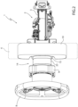
Figures 1 ,2 , and3 are three schematic perspective views, with parts removed for the sake of clarity, of a preferred embodiment of the steering column of the present invention shown in three different operating positions; -
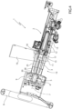
Figure 4 shows a schematic side view, with parts in section and parts removed for the sake of clarity, of a detail of the steering column ofFigures 1 ,2 , and3 ; and -
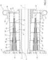
Figure 5 is a schematic side view, with parts in section and parts removed for the sake of clarity, of a detail ofFigure 4 . - Referring to
Figures 1 ,2 ,3 ,4 , and5 , thereference numeral 1 indicates, as a whole, a steering column for road vehicles comprising asteering shaft 2, which is configured to be connected to a body (not shown) of a road vehicle (not shown), and comprises, in turn, anupper post 3 projecting inside a passenger compartment (not shown) of the road vehicle (not shown) from adashboard 4. - The
steering column 1 further comprises atransmission shaft 5 comprising, in turn, anupper segment 6, which extends inside thepost 3, is mounted to rotate around a rotation axis 7, and is coupled in a sliding manner to thesegment 6 to perform rectilinear movements along theshaft 2. - The
segment 6 projects out of thepost 3, carries asteering wheel 8 connected at a free end thereof, and further supports agearbox control assembly 9 of the known type mounted between thedashboard 4 and thesteering wheel 8. - The
steering column 1 is further associated with acontrol panel 10, which projects upwards from thepost 3, and is locked on theshaft 2 by means of afixing fork 11 mounted below thepost 3. - In this case, the assembly defined by the
post 3, by thesegment 6, by thesteering wheel 8, by thegearbox control assembly 9, and by thecontrol panel 10, is coupled in a rotary manner to thedashboard 4 by means of a plurality ofball joints 12 obtained partly on afastening plate 13 of thefork 11 and partly on thedashboard 4. - The
steering column 1 is further provided with a coveringdevice 14 for an end segment of thepost 3. - The
device 14 comprises afirst sleeve 15, which extends around thepost 3 coaxially to the axis 7, is limited by an annular-shaped bottom wall 16 substantially perpendicular to the axis 7, and is axially locked on thecontrol panel 10 by engaging anannular flange 17 radially projecting outwards from thesleeve 15 into arecess 18 obtained partly on thecontrol panel 10 and partly on thefork 11. - The
sleeve 15 is provided with a plurality ofcylindrical guides 19, which are uniformly distributed around the axis 7 and thepost 3, and project from thewall 16 parallel to the axis 7. - The
device 14 further comprises asecond sleeve 20, which extends around thepost 3, and is axially locked on thegearbox control assembly 9 by means of a plurality of fixing screws (not shown). - The
sleeve 20 is limited by an annular-shaped bottom wall 21 substantially perpendicular to the axis 7, and is provided with a plurality ofcylindrical guides 22, which are uniformly distributed around the axis 7 and thepost 3, project from thewall 16 parallel to the axis 7, and are axially open at thewall 21. - In this case, the
device 14 further comprises athird sleeve 23, which extends around thepost 3, is limited by an annular-shaped bottom wall 24 substantially perpendicular to the axis 7, and is provided with a plurality ofcylindrical guides 25. - The
guides 25 are uniformly distributed around the axis 7 and thepost 3, project from thewall 24 parallel to the axis 7, are axially open at thewall 24, and are coupled in a sliding manner to theguides 19 of thesleeve 15. - In this case, the
device 14 further comprises afourth sleeve 26, which extends around thepost 3, is limited by an annular-shaped bottom wall 27 substantially perpendicular to the axis 7, and is provided with a plurality of cylindrical guides 28. - The guides 28 are uniformly distributed around the axis 7 and the
post 3, project from thewall 27 parallel to the axis 7, are axially open at thewall 27, and are coupled in a sliding manner to theguides 22 of thesleeve 20 and to theguides 25 of thesleeve 23. - Obviously, the
guides 19 are equal in number to the number of theguides 22, to the number of theguides 25, and to the number of the guides 28. - The
sleeve 20 has a smaller cross section than the cross section of thesleeve 26 so as to move inside thesleeve 26; thesleeve 26 has a smaller cross section than the cross section of thesleeve 23 so as to move inside thesleeve 23; and thesleeve 23 has a smaller cross section than the cross section of thesleeve 15 so as to move inside thesleeve 15. - The
device 14 further comprises aspring 29 interposed between eachguide 19 of thesleeve 15 and therelative guide 25 of thesleeve 23, aspring 30 interposed between eachguide 25 of thesleeve 23 and the relative guide 28 of thesleeve 26, and aspring 31 interposed between each guide 28 of thesleeve 26 and therelative guide 22 of thesleeve 20. - The
sleeves springs Figure 1 ), are movable to a retracted position (Figure 2 ) against the bias of thesprings limit stop flanges 32 obtained at the ends of theguides - With regard to what set forth above, it should be specified that the
sleeves - According to some not shown variations:
- the
sleeves sleeves - the number of
sleeves - the
sleeve 15 and, therefore, thedevice 14 are not connected to thecontrol panel 10 and are directly connected to thedashboard 4. - The
steering column 1 has some advantages mainly originating from the fact that the coveringdevice 14 has relatively reduced dimensions and a relatively high capacity to cover theupper post 3 of theshaft 2. In particular, the coveringdevice 14 has, when arranged in its extracted position, a length, measured between thecontrol panel 10 and thegearbox control assembly 9, at least of 120 mm.
Claims (12)
- A steering column for road vehicles comprising a steering shaft (2) having an upper post (3); a transmission shaft (5), which is housed in the steering shaft (2) and has an upper segment (6), which projects out of the upper post (3), is provided with a steering wheel (8) and is coupled to the upper post (3) in a rotary and axially sliding manner; and a covering device (14) for at least part of the upper post (3) of the steering shaft (2); and characterized in that the covering device (14) comprises at least a first sleeve (15) and a second sleeve (20), which extend around the upper post (3) of the steering shaft (2), are connected one to a dashboard (4) of a road vehicle and one to the upper segment (6) of the transmission shaft (5) and are movable relative to one another between an extracted position and a retracted position.
- The steering column according to claim 1, wherein the first sleeve (15) is directly fastened to the dashboard (4), in particular in a rotary manner.
- The steering column according to claim 1, wherein the first sleeve (15) is connected to the dashboard (4) through the interposition of a control panel (10) of the road vehicle.
- The steering column according to claim 3, wherein the first sleeve (15) is fixed to the control panel (10) and the control panel (10) is fastened to the dashboard (4), in particular in a rotary manner.
- The steering column according to any one of the preceding claims, wherein said first and second sleeves (15, 20) are coupled so as to slide relative to one another and the covering device (14) further comprises at least one spring (29, 30, 31) interposed between said first and second sleeves (15, 20) to move said first and second sleeves (15, 20) to their extracted position.
- The steering column according to any one of the preceding claims, wherein said first and second sleeves (15, 20) have respective annular limit stop flanges (32) to stop said first and second sleeves (15, 20) in their extracted position.
- The steering column according to any one of the claims from 1 to 4, wherein the covering device (14) further comprises at least a third sleeve (23, 26) mounted between said first and second sleeves (15, 20); said first, second and third sleeves (15, 20, 23, 26) being coupled to one another in a sliding manner so as to move between said retracted and extracted positions.
- The steering column according to claim 7, wherein the covering device (14) further comprises, for each pair of sleeves (15, 20, 23, 26) adjacent to one another, at least one respective spring (29, 30, 31) interposed between the adjacent sleeves (15, 20, 23, 26) to move them to their extracted position.
- The steering column according to claim 7 or 8, wherein each pair of sleeves (15, 20, 23, 26) adjacent to one another has a relative pair of annular limit stop flanges (32) to stop the adjacent sleeves (15, 20, 23, 26) in their extracted position.
- The steering column according to any one of the preceding claims and further comprising a gearbox control assembly (9) fixed to the upper segment (6) of the transmission shaft (5); the second sleeve (20) being fastened to the gearbox control assembly (9).
- The steering column according to any one of the preceding claims, wherein said first and second sleeves (15, 20) have respective cross sections that are different from one another so as to move inside one another between said extracted and retracted positions.
- The steering column according to any one of the preceding claims, wherein said sleeves (15, 20, 23, 26) are made of a stiff material, in particular a plastic material.
Applications Claiming Priority (1)
| Application Number | Priority Date | Filing Date | Title |
|---|---|---|---|
| IT102023000027870A IT202300027870A1 (en) | 2023-12-22 | 2023-12-22 | STEERING COLUMN FOR ROAD VEHICLES |
Publications (1)
| Publication Number | Publication Date |
|---|---|
| EP4574627A1 true EP4574627A1 (en) | 2025-06-25 |
Family
ID=90123929
Family Applications (1)
| Application Number | Title | Priority Date | Filing Date |
|---|---|---|---|
| EP24221752.9A Pending EP4574627A1 (en) | 2023-12-22 | 2024-12-19 | Steering column for road vehicles |
Country Status (3)
| Country | Link |
|---|---|
| US (1) | US12485951B2 (en) |
| EP (1) | EP4574627A1 (en) |
| IT (1) | IT202300027870A1 (en) |
Citations (4)
| Publication number | Priority date | Publication date | Assignee | Title |
|---|---|---|---|---|
| EP3083368A1 (en) * | 2013-12-17 | 2016-10-26 | Turk Traktor Ve Ziraat Makineleri Anonim Sirketi | A sealed, telescopic steering column cover |
| DE102020111495A1 (en) * | 2020-04-28 | 2021-10-28 | Audi Aktiengesellschaft | Device for covering a gap between an instrument panel and a steering column and a motor vehicle |
| US20220227410A1 (en) * | 2019-06-04 | 2022-07-21 | Bayerische Motoren Werke Aktiengesellschaft | Steering Column Cover and Steering Column Having a Steering Column Cover |
| US20220274639A1 (en) * | 2021-02-26 | 2022-09-01 | Hyundai Motor Company | Foldable steering system for vehicle |
Family Cites Families (12)
| Publication number | Priority date | Publication date | Assignee | Title |
|---|---|---|---|---|
| US4826466A (en) * | 1987-09-11 | 1989-05-02 | Arco Industries Corporation | Steering column boot |
| DE19644170C2 (en) * | 1996-10-24 | 2001-02-22 | Opel Adam Ag | Cladding for an axially and vertically adjustable steering column |
| JP4678704B2 (en) * | 2001-04-27 | 2011-04-27 | タカタ株式会社 | Seat belt device |
| DE10130931C1 (en) * | 2001-06-27 | 2002-08-22 | Daimler Chrysler Ag | Trim for a steering column |
| DE102018122767A1 (en) * | 2018-09-17 | 2020-03-19 | Thyssenkrupp Ag | Steering column and steer-by-wire steering system |
| DE102019201390A1 (en) * | 2019-02-04 | 2020-08-06 | Thyssenkrupp Ag | Steering column for a motor vehicle |
| US11061401B2 (en) * | 2019-10-29 | 2021-07-13 | Ford Global Technologies, Llc | Stowable steering wheel for autonomous vehicles |
| DE102019217279A1 (en) * | 2019-11-08 | 2021-05-12 | Thyssenkrupp Ag | Feedback actuator for a steering device of a motor vehicle |
| KR102667921B1 (en) * | 2019-11-18 | 2024-05-22 | 현대모비스 주식회사 | Motor-driven steering column apparatus |
| FR3106116B1 (en) * | 2020-01-15 | 2022-01-21 | Faurecia Interieur Ind | Masking device for steering assembly |
| WO2021224200A1 (en) * | 2020-05-07 | 2021-11-11 | Thyssenkrupp Presta Ag | Steering column for a motor vehicle |
| DE102022205275B3 (en) * | 2022-05-25 | 2022-12-15 | Volkswagen Aktiengesellschaft | Arrangement for covering a gap between an instrument panel and a steering column cover, motor vehicle |
-
2023
- 2023-12-22 IT IT102023000027870A patent/IT202300027870A1/en unknown
-
2024
- 2024-12-19 US US18/987,414 patent/US12485951B2/en active Active
- 2024-12-19 EP EP24221752.9A patent/EP4574627A1/en active Pending
Patent Citations (4)
| Publication number | Priority date | Publication date | Assignee | Title |
|---|---|---|---|---|
| EP3083368A1 (en) * | 2013-12-17 | 2016-10-26 | Turk Traktor Ve Ziraat Makineleri Anonim Sirketi | A sealed, telescopic steering column cover |
| US20220227410A1 (en) * | 2019-06-04 | 2022-07-21 | Bayerische Motoren Werke Aktiengesellschaft | Steering Column Cover and Steering Column Having a Steering Column Cover |
| DE102020111495A1 (en) * | 2020-04-28 | 2021-10-28 | Audi Aktiengesellschaft | Device for covering a gap between an instrument panel and a steering column and a motor vehicle |
| US20220274639A1 (en) * | 2021-02-26 | 2022-09-01 | Hyundai Motor Company | Foldable steering system for vehicle |
Also Published As
| Publication number | Publication date |
|---|---|
| IT202300027870A1 (en) | 2025-06-22 |
| US12485951B2 (en) | 2025-12-02 |
| US20250206367A1 (en) | 2025-06-26 |
Similar Documents
| Publication | Publication Date | Title |
|---|---|---|
| CN111372833B (en) | Steering columns for motor vehicles | |
| KR102075346B1 (en) | Variable steering wheel system and operation method thereof | |
| KR102822514B1 (en) | Steering column for vehicle | |
| US5520416A (en) | Power tilt, telescoping and internally collapsible steering column | |
| US20110162904A1 (en) | Lower type motor driven column apparatus | |
| EP1905664A2 (en) | Electrically adjustable telescopic steering apparatus | |
| US10093341B2 (en) | Steering device | |
| CN108349550B (en) | Wheel cover for a motor vehicle and motor vehicle equipped with such a wheel cover | |
| DE102019112875A1 (en) | Steering system of a vehicle and method for operating a steering system of a vehicle | |
| DE102015225522A1 (en) | Arrangement for a steer-by-wire steering | |
| DE102023117822B4 (en) | AXIALLY ADJUSTABLE STEERING COLUMN ASSEMBLY AND AXIAL POSITION DETECTION SYSTEM FOR A STEERING COLUMN ASSEMBLY | |
| EP4574627A1 (en) | Steering column for road vehicles | |
| EP3196066B1 (en) | Shifting device | |
| EP4424566B1 (en) | Motor vehicle and method for the reconfiguration of the motor vehicle | |
| CN115892189A (en) | Steering column assembly and vehicle | |
| CN111532331B (en) | Adjustable steering column for a motor vehicle | |
| GB2598584A (en) | Adjustable user input system | |
| KR102101665B1 (en) | Telescopic steering device | |
| KR102844892B1 (en) | Steering Column For Vehicle | |
| US7500414B2 (en) | Steering column device for vehicle | |
| US11708893B2 (en) | Shift device for vehicle | |
| US20250276731A1 (en) | Steering system for motor vehicle and motor vehicle comprising the same | |
| US11339874B2 (en) | System for operation of a gearbox for a motor vehicle | |
| JP2010164126A (en) | Supporting structure of telescopic shaft and vehicular steering device | |
| DE102023204740A1 (en) | STEER-BY-WIRE STEERING COLUMN ASSEMBLY |
Legal Events
| Date | Code | Title | Description |
|---|---|---|---|
| PUAI | Public reference made under article 153(3) epc to a published international application that has entered the european phase |
Free format text: ORIGINAL CODE: 0009012 |
|
| STAA | Information on the status of an ep patent application or granted ep patent |
Free format text: STATUS: THE APPLICATION HAS BEEN PUBLISHED |
|
| AK | Designated contracting states |
Kind code of ref document: A1 Designated state(s): AL AT BE BG CH CY CZ DE DK EE ES FI FR GB GR HR HU IE IS IT LI LT LU LV MC ME MK MT NL NO PL PT RO RS SE SI SK SM TR |
|
| STAA | Information on the status of an ep patent application or granted ep patent |
Free format text: STATUS: REQUEST FOR EXAMINATION WAS MADE |
|
| 17P | Request for examination filed |
Effective date: 20251202 |