EP4574412A1 - Press and animal-shed vehicle having such a press - Google Patents
Press and animal-shed vehicle having such a press Download PDFInfo
- Publication number
- EP4574412A1 EP4574412A1 EP24219531.1A EP24219531A EP4574412A1 EP 4574412 A1 EP4574412 A1 EP 4574412A1 EP 24219531 A EP24219531 A EP 24219531A EP 4574412 A1 EP4574412 A1 EP 4574412A1
- Authority
- EP
- European Patent Office
- Prior art keywords
- press
- roller
- pressure
- perforated
- adjusting means
- Prior art date
- Legal status (The legal status is an assumption and is not a legal conclusion. Google has not performed a legal analysis and makes no representation as to the accuracy of the status listed.)
- Pending
Links
Images
Classifications
-
- B—PERFORMING OPERATIONS; TRANSPORTING
- B30—PRESSES
- B30B—PRESSES IN GENERAL
- B30B9/00—Presses specially adapted for particular purposes
- B30B9/02—Presses specially adapted for particular purposes for squeezing-out liquid from liquid-containing material, e.g. juice from fruits, oil from oil-containing material
- B30B9/20—Presses specially adapted for particular purposes for squeezing-out liquid from liquid-containing material, e.g. juice from fruits, oil from oil-containing material using rotary pressing members, other than worms or screws, e.g. rollers, rings, discs
-
- A—HUMAN NECESSITIES
- A01—AGRICULTURE; FORESTRY; ANIMAL HUSBANDRY; HUNTING; TRAPPING; FISHING
- A01K—ANIMAL HUSBANDRY; AVICULTURE; APICULTURE; PISCICULTURE; FISHING; REARING OR BREEDING ANIMALS, NOT OTHERWISE PROVIDED FOR; NEW BREEDS OF ANIMALS
- A01K1/00—Housing animals; Equipment therefor
- A01K1/01—Removal of dung or urine ; Removal of manure from stables
- A01K1/0103—Removal of dung or urine ; Removal of manure from stables of liquid manure
Definitions
- the present invention relates to a press for separating a slurry such as faeces into a low-liquid fraction and into a liquid-rich fraction.
- slurry presses are generally used for separating slurry, a mixture of urine and faeces, into a liquid-rich fraction and into a low-liquid fraction.
- the low-liquid fraction predominantly contains manure fibres which are often used as litter.
- Such presses are relatively large and heavy and fitted in a stationary manner.
- a known type of manure press comprises a pressure roller which has a rubber coating and presses a liquid-rich fraction of the slurry through holes in a metal roller.
- a press of such a type is known from US6044980 .
- both perforated rollers are movably fitted in the frame of the press.
- spring assemblies which are adjustable by means of bolts and act on the axle of the corresponding perforated roller, it is possible to adjust the pressure of the perforated roller on the pressure roller for each perforated roller.
- a disadvantage of this press is that the adjusting of the pressure or the adjusting of the ratio between the pressure of the first and second pressing operation is difficult and that, in order to adjust the ratio, both spring assemblies have to be adjusted separately.
- a single adjusting means can be used to adjust the pressing pressure both for the pressing operation involving the combination of pressure roller and first perforated roller and the pressing operation involving the combination of pressure roller and second perforated roller.
- this adjustment for example an adjustment of a spring which exerts a force on the pressure roller, takes place at one location on the machine which is easily accessible for an operator.
- the use of a single adjusting means for two adjustments produces a compact machine. This is particularly advantageous if the press is fitted to a vehicle where weight and compactness are important.
- the press is configured to guide the pressed low-liquid fraction from the first pressing operation to an infeed for the second pressing operation.
- the central adjusting means engages with the axle of the pressure roller.
- the bearing of the axle of the pressure roller is not connected directly to the frame of the press, but can move slightly.
- a change of the force on the axle of the pressure roller changes the pressing pressure for both the first pressing operation and the second pressing operation.
- the central adjusting means is configured to adjust the angle at which the adjusting means engages with the axle.
- This angle is understood to mean the angle between the connecting line which connects the axle of the perforated roller to the pressure roller and the line along which the exerted force on the pressure roller runs. By adjusting this angle, it is possible to adjust the ratio between the pressing pressures for the first and second pressing operation. In this case, the pressure roller is supported on both perforated rollers.
- the central adjusting means comprises a lever that is movable about a rotation point, and the rotation point is displaceable.
- the shifting of the rotation point changes the engagement angle of the central adjusting means on the pressure roller in a constructionally simple manner. This construction also makes it possible for the lever to be able to be placed at some distance from the rollers.
- the central adjusting means comprises an adjustable force element in order to adjust the force with which the central adjusting means engages with the axle.
- This adjusting means may, for example, be a spring, the spring tension being adjustable by means of bolts.
- the force element comprises a plunger that is movable in a cylinder, which cylinder is fluidically connected to a fluid pump such as a compressor in order to be able to change the pressure in the cylinder.
- Fluidically connected is understood to mean that the pressing space of the fluid pump is connected via a line containing a fluid, such as compressed air, to the plunger.
- the central adjusting means comprises a pressure or force sensor for delivering a force signal representative of the pressing pressure of the pressure roller on the first and/or second perforated roller and the fluid pump is controllable on the basis of the force signal.
- the pressing pressure can lapse due to play or wear.
- the press comprises a drive for driving only one or both perforated rollers.
- the pressure roller is driven by the friction with the driven perforated roller(s). Since the perforated roller is always at a fixed location on the press, a simple remote drive with a motor is possible.
- a drive for the pressure roller which is movable with respect to the frame requires a cumbersome construction.
- An additional advantage of the fact that not all the rollers are driven is that, in the event of a blockage, the non-driven roller can stop and cannot be damaged.
- the second perforated roller comprises fewer holes than the first perforated roller, preferably between 5% and 20% of the numbers of the first perforated roller.
- the second perforated roller comprises fewer holes than the first perforated roller, preferably between 5% and 20% of the numbers of the first perforated roller.
- the second perforated roller comprises smaller holes than the first perforated roller. Due to the smaller holes, the pressing pressure on the second perforated roller can be greater, without a disproportionately large amount of solid matter such as fibres remaining. With smaller holes, the solid matter has a lower tendency to be pressed through the holes in the case of the higher pressures.
- the press comprises a pressing space with side walls for containing the pressure roller and the first and, respectively, second perforated roller, wherein the side walls of the pressing space fit tightly against the pressure roller.
- the side of the pressure roller comprises a substance that slides easily in order to provide good sealing against the side wall without much friction.
- the press comprises a moisture sensor for delivering a moisture signal and the force element is controllable on the basis of the moisture signal.
- the material to be pressed can change in terms of moisture content.
- the moisture content of cow faeces can be greatly dependent on the feed composition or on the time of year.
- the moisture sensor may be placed in the infeed of the product to be pressed or in the outfeed of the low-liquid flow.
- the press 1 is configured to guide the pressed low-liquid fraction from the first pressing operation to an infeed for the second pressing operation.
- the second perforated roller 5 comprises approximately 10% of the number of holes 14 of the first perforated roller 4.
- the second perforated roller 5 comprises smaller holes 15 than the first perforated roller 4.
- the press 1 comprises a pressing space 17 with side walls 16 for containing a supply of faeces 2.
- the pressure roller 3 and the first perforated roller 4 form the lower boundary of this pressing space 17.
- the pressure roller 3 is provided with a smooth plastic washer 23.
- the first and, respectively, second perforated roller 5 extend through at least one side wall 16. The pressed liquid-rich fraction can thus flow via the interior of the perforated rollers 4, 5 to outside the pressing space 17.
- the perforated rollers 4, 5 are provided, on the inner side, with openings in the supports.
- FIG. 2 shows, in more detail, a side view of the outside of the pressing space 17.
- the press 1 comprises a drive in the form of an electric motor 13 for driving only one or both perforated rollers 4, 5. To this end, this electric motor 13 drives the axles of both perforated rollers 4, 5 via two chains.
- the circumferential speed of the two perforated rollers 4, 5 is the same in this case.
- the circumference of the pressure roller 3 and the two perforated rollers 4, 5 is indicated by an interrupted line.
- the pressure roller 3 is solely driven by friction with the perforated rollers 4, 5.
- a perforated roller 4, 5 is driven by a motor fitted directly to the axle of the perforated roller 4, 5.
- a central adjusting means 6 is fitted, which engages with the axle 7 of the pressure roller. This is configured to adjust the angle ⁇ at which the central adjusting means 6 engages with the axle 7.
- the central adjusting means 6 further comprises a lever 8 that is movable about a rotation point 9, wherein the rotation point 9 is displaceable. To this end, the bearing of the rotation point 9 is displaceable in a vertical direction via slotted holes (not depicted). This bearing is able to be secured by means of bolts (not depicted).
- the central adjusting means 6 further comprises an adjustable force element 10 in order to adjust the force with which the central adjusting means 6 engages with the axle 7.
- this force element 11 consists of a tension spring.
- the tension at this tension spring is adjustable in a continuously variable manner with the aid of bolts in a manner known per se.
- the force element 10 comprises a plunger that is movable in a cylinder, which cylinder is fluidically connected to a fluid pump in the form of an air compressor 11 in order to be able to change the pressure in the cylinder.
- the central adjusting means 6 further comprises a pressure or force sensor 12 for delivering a force signal representative of the pressing pressure of the pressure roller 3 on the first and/or second perforated roller 4, 5 and the fluid pump is controllable on the basis of the force signal.
- a pressure sensor 12 which measures the pressure in the plunger space 25 of the cylinder is depicted. This pressure is representative of the force exerted via the lever 8 on the pressure roller 3.
- a pressure vessel 24 is fitted which is connected to the fluid line to the cylinder.
- the pressure in the plunger space 25 remains stable by virtue of the fact that the size of this plunger space 25 can vary slightly depending on the quantity of material located between the pressure roller 3 and a perforated roller 4, 5.
- Figure 3 shows an autonomous animal-shed vehicle 19 having a press 1 and having a faeces pick-up device 20 for picking up faeces 2 from a floor 21 and comprising a faeces feed 22 for feeding the picked-up faeces 2 to the press 1.
- the vehicle 19 can move autonomously between animals in an animal space and pick up faeces 2 lying on a urine-permeable floor 21.
- the faeces pick-up device 20 is provided with a pusher 27 which feeds faeces 2 lying on the floor to a conveyor belt 28.
- the animal-shed vehicle 19 operates as follows: faeces 2 is scraped up by the pusher 27 and carried along by the conveyor belt 28 along a guide plate 29. Faeces 2 is collected at the top in the pressing space 17. At the bottom of the pressing space 17, the faeces 2 is pressed between the pressure roller 3 and the first perforated roller 4 in a first pressing operation. Fibres and other solid substances are carried along between the pressure roller 3 and the first perforated roller 4 and subsequently fall into the space between the pressure roller 3 and the second perforated roller 5. The parts adhering to the surface of the first perforated roller 4 are scraped off by a scraper 30 (see also Figure 1 ).
- a liquid-rich fraction is pressed through the holes 15 of the first perforated roller 4 to the interior of the perforated roller 4. This fraction can flow through the interior of the perforated roller 4 to the side, where it can exit the perforated roller 4 on the outside of the side wall 16. The liquid-rich fraction subsequently flows into a liquid container 31 on the vehicle 19.
- the low-liquid fraction from the first pressing operation passes through a second pressing operation by means of the second perforated roller 5 in an identical way as described above for the first pressing operation.
- the low-liquid fraction coming from this second pressing operation has a high proportion of manure fibres and is collected in the fibre space 33.
- a spreading device (not depicted) spreads the fibres from the fibre space 33 in the bedding of the animals.
- the liquid in the liquid container 31 is unloaded at a fixed dumping site in the animal shed.
- the moisture content of the fibres is continuously measured using a moisture sensor 18 which delivers a moisture signal to a controller 32. If the moisture content is higher than a setting, the controller 32 controls the compressor 11 to a higher pressure. The higher pressure has the effect that the cylinder exerts a higher force on the lever, which in turn presses the pressure roller 3 more tightly against the perforated rollers 4, 5.
- the pressure in the plunger space 25 is continuously measured by the pressure sensor 12. If the measured pressure is lower than the desired level, for example due to a small leakage, the compressor 11 is activated until the desired pressure is reached.
- the ratio between the first and second pressing operation has to be able to be adapted.
- This ratio is determined by the ratio between the pressing pressure of the first and second pressing operation.
- This ratio can be easily adapted by changing the placement of the rotation point 9. This changes the angle ⁇ ( Figure 2 ) without changing the total force on the pressure roller 3.
- the engagement of the connecting element 26 with the lever 8 is able to be changed, as a result of which the angle ⁇ changes.
- the transmission of force from the force element 10 to the pressure roller 3 takes place via a cable, wherein the one end of the cable is connected to the plunger of the force element 10 and the other end is connected to the pressure roller 3.
- the cable is guided via guide rollers, wherein a guide roller is rotatable about the rotation point 9. The angle ⁇ that the cable forms with the pressure roller 3 is able to be changed by adjusting the rotation point 9 for this guide roller.
- the press 1 according to the invention is described as an independent press 1 having a pressure roller 3 and two perforated rollers 4, 5. However, this combination can also form part of a larger unit, in which additional pressing operations take place upstream or downstream of the product flow.
- a press 1 for pressing faeces 2 is described in the described examples, the invention is not limited to faeces 2 or other types of manure such as slurry, but rather is also suitable for other applications, such as the pressing of sewage sludge, food flows such as fruit juices, or slurries of paper pulp.
Landscapes
- Engineering & Computer Science (AREA)
- Mechanical Engineering (AREA)
- Treatment Of Sludge (AREA)
- Press Drives And Press Lines (AREA)
Abstract
Press (1) for separating a slurry such as faeces (2) into a low-liquid fraction and into a liquid-rich fraction, comprising a pressure roller (3) with a flexible surface, a first and second perforated roller (4, 5) in order to, in cooperation with the pressure roller (3), carry out a first and, respectively, second pressing operation wherein the liquid-rich fraction is pressed through the holes of the perforated roller (4, 5), first adjusting means for adjusting the pressing pressure of the pressure roller (3) on the first perforated roller (4) and second adjusting means for adjusting the pressing pressure of the pressure roller (3) on the second perforated roller (5), wherein a central adjusting means (6) comprises the first and second adjusting means.
Description
- The present invention relates to a press for separating a slurry such as faeces into a low-liquid fraction and into a liquid-rich fraction.
- In agriculture, slurry presses are generally used for separating slurry, a mixture of urine and faeces, into a liquid-rich fraction and into a low-liquid fraction. The low-liquid fraction predominantly contains manure fibres which are often used as litter. Such presses are relatively large and heavy and fitted in a stationary manner. A known type of manure press comprises a pressure roller which has a rubber coating and presses a liquid-rich fraction of the slurry through holes in a metal roller. A press of such a type is known from
US6044980 . In this manure press, the pressure roller is pressed against a first roller with holes (perforated roller) for a first pressing operation, after which the pressed low-liquid fraction is subjected to a second pressing operation by the same pressure roller and a second perforated roller. In order to be able to adjust the pressing pressure, for example to regulate the ratio between liquid-rich fraction and manure fibres, both perforated rollers are movably fitted in the frame of the press. By way of spring assemblies which are adjustable by means of bolts and act on the axle of the corresponding perforated roller, it is possible to adjust the pressure of the perforated roller on the pressure roller for each perforated roller. A disadvantage of this press is that the adjusting of the pressure or the adjusting of the ratio between the pressure of the first and second pressing operation is difficult and that, in order to adjust the ratio, both spring assemblies have to be adjusted separately. - It is the object of the invention to provide a compact and easily adjustable slurry press.
- This is achieved by means of a press according to
Claim 1. A single adjusting means can be used to adjust the pressing pressure both for the pressing operation involving the combination of pressure roller and first perforated roller and the pressing operation involving the combination of pressure roller and second perforated roller. Preferably, this adjustment, for example an adjustment of a spring which exerts a force on the pressure roller, takes place at one location on the machine which is easily accessible for an operator. The use of a single adjusting means for two adjustments produces a compact machine. This is particularly advantageous if the press is fitted to a vehicle where weight and compactness are important. - In an advantageous embodiment of the invention, the press is configured to guide the pressed low-liquid fraction from the first pressing operation to an infeed for the second pressing operation. By carrying out two pressing operations one after the other, in the first pressing operation it is possible to set the best process conditions, such as pressing pressure and hole density, for a relatively moist infeed, whereas for the second pressing operation it is possible to set process parameters for a relatively dry infeed.
- In a further advantageous embodiment of the invention, the central adjusting means engages with the axle of the pressure roller. For this reason, the bearing of the axle of the pressure roller is not connected directly to the frame of the press, but can move slightly. A change of the force on the axle of the pressure roller changes the pressing pressure for both the first pressing operation and the second pressing operation.
- In a particular embodiment of the invention, the central adjusting means is configured to adjust the angle at which the adjusting means engages with the axle. This angle is understood to mean the angle between the connecting line which connects the axle of the perforated roller to the pressure roller and the line along which the exerted force on the pressure roller runs. By adjusting this angle, it is possible to adjust the ratio between the pressing pressures for the first and second pressing operation. In this case, the pressure roller is supported on both perforated rollers. It is only when the central adjusting means exerts a force on the axle of the pressure roller along a traction line which is exactly in the middle between the connecting lines from the rotation axle of the pressure roller to the axle of the corresponding perforated roller that the pressure on the first and, respectively, second perforated roller is the same. Changing the orientation of this traction line changes the ratio between the pressures on the first and, respectively, second perforated roller.
- In a further particular embodiment of the invention, the central adjusting means comprises a lever that is movable about a rotation point, and the rotation point is displaceable. The shifting of the rotation point changes the engagement angle of the central adjusting means on the pressure roller in a constructionally simple manner. This construction also makes it possible for the lever to be able to be placed at some distance from the rollers.
- It is also advantageous if the central adjusting means comprises an adjustable force element in order to adjust the force with which the central adjusting means engages with the axle. This adjusting means may, for example, be a spring, the spring tension being adjustable by means of bolts. By fastening the force element to the long side of the lever, it is possible to obtain a large force on the pressure roller in a simple manner.
- In particular, the force element comprises a plunger that is movable in a cylinder, which cylinder is fluidically connected to a fluid pump such as a compressor in order to be able to change the pressure in the cylinder. Fluidically connected is understood to mean that the pressing space of the fluid pump is connected via a line containing a fluid, such as compressed air, to the plunger.
- In a further particular embodiment of the invention, the central adjusting means comprises a pressure or force sensor for delivering a force signal representative of the pressing pressure of the pressure roller on the first and/or second perforated roller and the fluid pump is controllable on the basis of the force signal. The pressing pressure can lapse due to play or wear. By continuously measuring the force actually applied and controlling the fluid pump on the basis of this measurement, it is possible for the pressure in the cylinder, and thus the force on the central adjusting means, to be kept constant.
- Preferably, the press comprises a drive for driving only one or both perforated rollers. In this case, the pressure roller is driven by the friction with the driven perforated roller(s). Since the perforated roller is always at a fixed location on the press, a simple remote drive with a motor is possible. A drive for the pressure roller which is movable with respect to the frame requires a cumbersome construction. An additional advantage of the fact that not all the rollers are driven is that, in the event of a blockage, the non-driven roller can stop and cannot be damaged.
- In a further preferred embodiment, the second perforated roller comprises fewer holes than the first perforated roller, preferably between 5% and 20% of the numbers of the first perforated roller. In the case of the low-liquid fraction being fed from the first pressing operation to the second pressing operation, since there will then be less moisture in the infeed, also fewer holes will be required to discharge the limited moisture. Experimentation has shown that the above-mentioned relative numbers provide the best results with the highest solids content in the case of two successive pressing operations.
- In yet a further preferred embodiment, the second perforated roller comprises smaller holes than the first perforated roller. Due to the smaller holes, the pressing pressure on the second perforated roller can be greater, without a disproportionately large amount of solid matter such as fibres remaining. With smaller holes, the solid matter has a lower tendency to be pressed through the holes in the case of the higher pressures.
- In an advantageous embodiment of the invention, the press comprises a pressing space with side walls for containing the pressure roller and the first and, respectively, second perforated roller, wherein the side walls of the pressing space fit tightly against the pressure roller. Preferably, the side of the pressure roller comprises a substance that slides easily in order to provide good sealing against the side wall without much friction.
- In yet a further advantageous embodiment of the invention, the press comprises a pressing space with side walls for containing the pressure roller and the first and, respectively, second perforated roller, and wherein the first and, respectively, second perforated roller extend through at least one side wall. The pressure roller presses the liquid-rich fraction through the holes of a perforated roller to the inside of the partially hollow perforated roller. Via the passage through the side wall, the liquid-rich fraction is discharged outside the side wall.
- In particular, the press comprises a moisture sensor for delivering a moisture signal and the force element is controllable on the basis of the moisture signal. The material to be pressed can change in terms of moisture content. In order to obtain an end product with a consistent composition, it is necessary to adjust the degree of pressing and thus the force on the pressure roller. For instance, the moisture content of cow faeces can be greatly dependent on the feed composition or on the time of year. The moisture sensor may be placed in the infeed of the product to be pressed or in the outfeed of the low-liquid flow.
- The invention also relates to an animal-shed vehicle having a press according to the invention, wherein the animal-shed vehicle comprises a faeces pick-up device for picking up faeces from a floor and comprises a faeces feed for feeding the picked-up faeces to the press.
- The invention will be discussed in more detail below with reference to a drawing, in which:
-
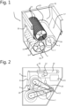
Figure 1 shows a schematic cut-away depiction of the press according to the invention; -
Figure 2 shows a schematic side view of rollers of the press according to the invention; -
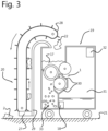
Figure 3 shows an animal-shed vehicle having a press according to the invention for making manure fibres on-site. -
Figure 1 shows apress 1 for separating a slurry in the form of faeces 2 into a low-liquid fraction and into a liquid-rich fraction, comprising apressure roller 3 with a flexible surface 3A, a first and second perforatedroller pressure roller 3, carry out a first and, respectively, second pressing operation wherein the liquid-rich fraction is pressed through theholes roller pressure roller 3 on the first perforatedroller 4 and second adjusting means for adjusting the pressing pressure of thepressure roller 3 on the second perforatedroller 5, wherein a central adjusting means comprises the first and second adjusting means. Thepress 1 is configured to guide the pressed low-liquid fraction from the first pressing operation to an infeed for the second pressing operation. The secondperforated roller 5 comprises approximately 10% of the number ofholes 14 of the firstperforated roller 4. The secondperforated roller 5 comprisessmaller holes 15 than the firstperforated roller 4. - The
press 1 comprises apressing space 17 withside walls 16 for containing a supply of faeces 2. Thepressure roller 3 and the firstperforated roller 4 form the lower boundary of thispressing space 17. The twoside walls 16, which are perpendicular to therotation axle 7 of thepressure roller 3, fit tightly against thepressure roller 3. At the sides, thepressure roller 3 is provided with a smoothplastic washer 23. The first and, respectively, secondperforated roller 5 extend through at least oneside wall 16. The pressed liquid-rich fraction can thus flow via the interior of theperforated rollers pressing space 17. To this end, theperforated rollers -
Figure 2 shows, in more detail, a side view of the outside of thepressing space 17. Thepress 1 comprises a drive in the form of anelectric motor 13 for driving only one or both perforatedrollers electric motor 13 drives the axles of both perforatedrollers perforated rollers pressure roller 3 and the twoperforated rollers pressure roller 3 is solely driven by friction with theperforated rollers perforated roller perforated roller axle 7 of the pressure roller. This is configured to adjust the angle α at which the central adjusting means 6 engages with theaxle 7. The central adjusting means 6 further comprises alever 8 that is movable about arotation point 9, wherein therotation point 9 is displaceable. To this end, the bearing of therotation point 9 is displaceable in a vertical direction via slotted holes (not depicted). This bearing is able to be secured by means of bolts (not depicted). The central adjusting means 6 further comprises anadjustable force element 10 in order to adjust the force with which the central adjusting means 6 engages with theaxle 7. - In one embodiment that is not depicted, this
force element 11 consists of a tension spring. The tension at this tension spring is adjustable in a continuously variable manner with the aid of bolts in a manner known per se. - The part of the
lever 8 below therotation point 9, depicted inFigure 2 , is connected to the bearing of theaxle 7 by means of a connectingelement 26. This bearing is slightly displaceably connected to theside wall 16. - In the embodiment depicted in
Figure 2 , theforce element 10 comprises a plunger that is movable in a cylinder, which cylinder is fluidically connected to a fluid pump in the form of anair compressor 11 in order to be able to change the pressure in the cylinder. The central adjusting means 6 further comprises a pressure orforce sensor 12 for delivering a force signal representative of the pressing pressure of thepressure roller 3 on the first and/or secondperforated roller pressure sensor 12 which measures the pressure in theplunger space 25 of the cylinder is depicted. This pressure is representative of the force exerted via thelever 8 on thepressure roller 3. In order to not allow the pressure to fluctuate too greatly with fluctuations in the distance between thepressure roller 3 and theperforated roller pressure vessel 24 is fitted which is connected to the fluid line to the cylinder. In this way, the pressure in theplunger space 25 remains stable by virtue of the fact that the size of thisplunger space 25 can vary slightly depending on the quantity of material located between thepressure roller 3 and aperforated roller -
Figure 3 shows an autonomous animal-shedvehicle 19 having apress 1 and having a faeces pick-updevice 20 for picking up faeces 2 from afloor 21 and comprising a faeces feed 22 for feeding the picked-up faeces 2 to thepress 1. Thevehicle 19 can move autonomously between animals in an animal space and pick up faeces 2 lying on a urine-permeable floor 21. The faeces pick-updevice 20 is provided with apusher 27 which feeds faeces 2 lying on the floor to aconveyor belt 28. - The animal-shed
vehicle 19 operates as follows: faeces 2 is scraped up by thepusher 27 and carried along by theconveyor belt 28 along aguide plate 29. Faeces 2 is collected at the top in thepressing space 17. At the bottom of thepressing space 17, the faeces 2 is pressed between thepressure roller 3 and the firstperforated roller 4 in a first pressing operation. Fibres and other solid substances are carried along between thepressure roller 3 and the firstperforated roller 4 and subsequently fall into the space between thepressure roller 3 and the secondperforated roller 5. The parts adhering to the surface of the firstperforated roller 4 are scraped off by a scraper 30 (see alsoFigure 1 ). A liquid-rich fraction is pressed through theholes 15 of the firstperforated roller 4 to the interior of theperforated roller 4. This fraction can flow through the interior of theperforated roller 4 to the side, where it can exit theperforated roller 4 on the outside of theside wall 16. The liquid-rich fraction subsequently flows into aliquid container 31 on thevehicle 19. - The low-liquid fraction from the first pressing operation passes through a second pressing operation by means of the second
perforated roller 5 in an identical way as described above for the first pressing operation. The low-liquid fraction coming from this second pressing operation has a high proportion of manure fibres and is collected in thefibre space 33. A spreading device (not depicted) spreads the fibres from thefibre space 33 in the bedding of the animals. The liquid in theliquid container 31 is unloaded at a fixed dumping site in the animal shed. - The moisture content of the fibres is continuously measured using a
moisture sensor 18 which delivers a moisture signal to acontroller 32. If the moisture content is higher than a setting, thecontroller 32 controls thecompressor 11 to a higher pressure. The higher pressure has the effect that the cylinder exerts a higher force on the lever, which in turn presses thepressure roller 3 more tightly against theperforated rollers plunger space 25 is continuously measured by thepressure sensor 12. If the measured pressure is lower than the desired level, for example due to a small leakage, thecompressor 11 is activated until the desired pressure is reached. - In some cases, for example in the case of very dry faeces or wet faeces, the ratio between the first and second pressing operation has to be able to be adapted. This ratio is determined by the ratio between the pressing pressure of the first and second pressing operation. This ratio can be easily adapted by changing the placement of the
rotation point 9. This changes the angle α (Figure 2 ) without changing the total force on thepressure roller 3. In one embodiment that is not depicted, the engagement of the connectingelement 26 with thelever 8 is able to be changed, as a result of which the angle α changes. - In an alternative embodiment that is not depicted, the transmission of force from the
force element 10 to thepressure roller 3 takes place via a cable, wherein the one end of the cable is connected to the plunger of theforce element 10 and the other end is connected to thepressure roller 3. The cable is guided via guide rollers, wherein a guide roller is rotatable about therotation point 9. The angle α that the cable forms with thepressure roller 3 is able to be changed by adjusting therotation point 9 for this guide roller. - The
press 1 according to the invention is described as anindependent press 1 having apressure roller 3 and twoperforated rollers - Although a
press 1 for pressing faeces 2 is described in the described examples, the invention is not limited to faeces 2 or other types of manure such as slurry, but rather is also suitable for other applications, such as the pressing of sewage sludge, food flows such as fruit juices, or slurries of paper pulp.
Claims (15)
- Press (1) for separating a slurry such as faeces (2) into a low-liquid fraction and into a liquid-rich fraction, comprising a pressure roller (3) with a flexible surface, a first and second perforated roller (4, 5) in order to, in cooperation with the pressure roller (3), carry out a first and, respectively, second pressing operation wherein the liquid-rich fraction is pressed through the holes of the perforated roller (4, 5), first adjusting means for adjusting the pressing pressure of the pressure roller (3) on the first perforated roller (4) and second adjusting means for adjusting the pressing pressure of the pressure roller (3) on the second perforated roller (5), wherein a central adjusting means (6) comprises the first and second adjusting means.
- Press (1) according to Claim 1, characterized in that the press (1) is configured to guide the pressed low-liquid fraction from the first pressing operation to an infeed for the second pressing operation.
- Press (1) according to Claim 1 or 2, characterized in that the central adjusting means (6) engages with the axle (7) of the pressure roller (3).
- Press (1) according to Claim 3, characterized in that the central adjusting means (6) is configured to adjust the angle (α) at which the central adjusting means (6) engages with the axle (7).
- Press (1) according to Claim 4, characterized in that the central adjusting means (6) comprises a lever (8) that is movable about a rotation point (9), and wherein the rotation point (9) is displaceable.
- Press (1) according to one of Claims 3 to 5, characterized in that the central adjusting means (6) comprises an adjustable force element (10) in order to adjust the force with which the central adjusting means (6) engages with the axle (7).
- Press (1) according to Claim 6, characterized in that the force element (10) comprises a plunger that is movable in a cylinder, which cylinder is fluidically connected to a fluid pump such as a compressor (11) in order to be able to change the pressure in the cylinder.
- Press (1) according to Claim 7, characterized in that the central adjusting means (6) comprises a pressure or force sensor (12) for delivering a force signal representative of the pressing pressure of the pressure roller (3) on the first and/or second perforated roller (4, 5) and the fluid pump (11) is controllable on the basis of the force signal.
- Press (1) according to one of the preceding claims, characterized in that the press (1) comprises a drive (13) for driving only one or both perforated rollers (4, 5).
- Press (1) according to one of the preceding claims, characterized in that the second perforated roller (5) comprises fewer holes (14) than the first perforated roller (4), preferably between 5% and 20% of the number of the first perforated roller (4).
- Press (1) according to one of the preceding claims, characterized in that the second perforated roller (5) comprises smaller holes (14) than the first perforated roller (4).
- Press (1) according to one of the preceding claims, characterized in that the press (1) comprises a pressing space (17) with side walls (16) for containing the pressure roller (3) and the first and, respectively, second perforated roller (4, 5), wherein at least one and preferably both side walls (16) of the pressing space (17) fit tightly against the pressure roller (3).
- Press (1) according to one of the preceding claims, characterized in that the press (1) comprises a pressing space (17) with side walls (16) for containing the pressure roller (3) and the first and, respectively, second perforated roller (4, 5), and wherein the first and, respectively, second perforated roller (4, 5) extend through at least one side wall (16).
- Press (1) according to one of Claims 6 to 13, characterized in that the press (1) comprises a moisture sensor (18) for delivering a moisture signal and the force element (10) is controllable on the basis of the moisture signal.
- Animal-shed vehicle (19) having a press (1) according to one of the preceding claims, characterized in that the animal-shed vehicle (19) comprises a faeces pick-up device (20) for picking up faeces (2) from a floor (21) and comprises a faeces feed (22) for feeding the picked-up faeces (2) to the press (1).
Applications Claiming Priority (1)
| Application Number | Priority Date | Filing Date | Title |
|---|---|---|---|
| NL2036573A NL2036573B1 (en) | 2023-12-19 | 2023-12-19 | Press and stable vehicle with such a press |
Publications (1)
| Publication Number | Publication Date |
|---|---|
| EP4574412A1 true EP4574412A1 (en) | 2025-06-25 |
Family
ID=90458064
Family Applications (1)
| Application Number | Title | Priority Date | Filing Date |
|---|---|---|---|
| EP24219531.1A Pending EP4574412A1 (en) | 2023-12-19 | 2024-12-12 | Press and animal-shed vehicle having such a press |
Country Status (2)
| Country | Link |
|---|---|
| EP (1) | EP4574412A1 (en) |
| NL (1) | NL2036573B1 (en) |
Citations (4)
| Publication number | Priority date | Publication date | Assignee | Title |
|---|---|---|---|---|
| US6044980A (en) | 1997-01-30 | 2000-04-04 | J. Houle & Fils Inc. | Drum press extractor |
| GB2378401A (en) * | 1999-09-22 | 2003-02-12 | Carier Bulk Materials Handling | Rotary drum filter |
| CN200957661Y (en) * | 2006-08-04 | 2007-10-10 | 开封市四达农产品设备有限公司 | Multi-roller starch slag water pressurizer |
| US20170215371A1 (en) * | 2014-09-02 | 2017-08-03 | Lely Patent N.V. | Device for the maintenance of floor cover material present on an animal-shed floor |
Family Cites Families (3)
| Publication number | Priority date | Publication date | Assignee | Title |
|---|---|---|---|---|
| US4192228A (en) * | 1972-03-17 | 1980-03-11 | Celanese Canada Limited | Method to express liquid from wet fibrous material |
| JP4913202B2 (en) * | 2009-11-09 | 2012-04-11 | 株式会社高井製作所 | Roller type solid-liquid separator |
| CN109665691A (en) * | 2019-02-27 | 2019-04-23 | 河北瀚良农业科技有限公司 | The solid-liquid separating method and solid-liquid separating machine of the waste containing sandstone |
-
2023
- 2023-12-19 NL NL2036573A patent/NL2036573B1/en active
-
2024
- 2024-12-12 EP EP24219531.1A patent/EP4574412A1/en active Pending
Patent Citations (4)
| Publication number | Priority date | Publication date | Assignee | Title |
|---|---|---|---|---|
| US6044980A (en) | 1997-01-30 | 2000-04-04 | J. Houle & Fils Inc. | Drum press extractor |
| GB2378401A (en) * | 1999-09-22 | 2003-02-12 | Carier Bulk Materials Handling | Rotary drum filter |
| CN200957661Y (en) * | 2006-08-04 | 2007-10-10 | 开封市四达农产品设备有限公司 | Multi-roller starch slag water pressurizer |
| US20170215371A1 (en) * | 2014-09-02 | 2017-08-03 | Lely Patent N.V. | Device for the maintenance of floor cover material present on an animal-shed floor |
Also Published As
| Publication number | Publication date |
|---|---|
| NL2036573B1 (en) | 2025-07-01 |
Similar Documents
| Publication | Publication Date | Title |
|---|---|---|
| FI65765C (en) | ANORDNING FOER BEHANDLING AV SLAM | |
| US7335311B2 (en) | Sludge treatment | |
| EP3238832B2 (en) | Powder conveying device for conveying coating powder to a powder applicator, powder coating installation and method for operating the powder conveying device | |
| US4412485A (en) | Press for expressing liquid from a mass | |
| DE69702391T2 (en) | ARRANGEMENT AND METHOD FOR CLEANING A CONVEYOR BELT | |
| NL8101615A (en) | DISTRIBUTION CABINET. | |
| US5133872A (en) | Method and apparatus for controlling throughput in a beltpress | |
| US4817517A (en) | Method and apparatus for making food pellets | |
| CN103269836A (en) | Method and device for wetting particle material, in particular fibers and/or chips, with a fluid | |
| EP0842763B1 (en) | Apparatus for the controlled spraying of a lubricating product in powder form on punches and dies in tablet presses | |
| JP2010506571A (en) | Adjustable roller device for spreading material | |
| US20210197512A1 (en) | Moisture extraction press and moisture removal from wood materials | |
| NL2036573B1 (en) | Press and stable vehicle with such a press | |
| GB2035617A (en) | Control system for a dewatering press | |
| US5109764A (en) | Double screen belt press with a wedge compression zone for dewatering mixtures of fibrous material suspensions | |
| US5137489A (en) | Low pressure continuous feed screw press | |
| US5411669A (en) | Process and apparatus for treating pre-concentrated solid-liquid mixture streams | |
| US3877366A (en) | Press Filter | |
| EP1216610A2 (en) | Fertilizer spreader | |
| DE10330949A1 (en) | Method and plant for the automated acceptance and processing of grapes | |
| EP1420944A1 (en) | Briquetting system | |
| CN210057577U (en) | High-efficiency belt type filter-pressing dewatering system | |
| EP0295339A2 (en) | Method and apparatus for separating liquid out of a substance containing liquid and solid material | |
| CN112209593A (en) | Squeezing method of continuous deep dehydration equipment | |
| DE4423555C2 (en) | Vacuum extrusion press |
Legal Events
| Date | Code | Title | Description |
|---|---|---|---|
| PUAI | Public reference made under article 153(3) epc to a published international application that has entered the european phase |
Free format text: ORIGINAL CODE: 0009012 |
|
| STAA | Information on the status of an ep patent application or granted ep patent |
Free format text: STATUS: THE APPLICATION HAS BEEN PUBLISHED |
|
| AK | Designated contracting states |
Kind code of ref document: A1 Designated state(s): AL AT BE BG CH CY CZ DE DK EE ES FI FR GB GR HR HU IE IS IT LI LT LU LV MC ME MK MT NL NO PL PT RO RS SE SI SK SM TR |
|
| STAA | Information on the status of an ep patent application or granted ep patent |
Free format text: STATUS: REQUEST FOR EXAMINATION WAS MADE |
|
| 17P | Request for examination filed |
Effective date: 20260102 |