EP4574299A1 - Coiling machine and production method for coil springs - Google Patents
Coiling machine and production method for coil springs Download PDFInfo
- Publication number
- EP4574299A1 EP4574299A1 EP23854707.9A EP23854707A EP4574299A1 EP 4574299 A1 EP4574299 A1 EP 4574299A1 EP 23854707 A EP23854707 A EP 23854707A EP 4574299 A1 EP4574299 A1 EP 4574299A1
- Authority
- EP
- European Patent Office
- Prior art keywords
- wire
- laser light
- equal
- irradiation
- coil spring
- Prior art date
- Legal status (The legal status is an assumption and is not a legal conclusion. Google has not performed a legal analysis and makes no representation as to the accuracy of the status listed.)
- Pending
Links
Images





Classifications
-
- B—PERFORMING OPERATIONS; TRANSPORTING
- B21—MECHANICAL METAL-WORKING WITHOUT ESSENTIALLY REMOVING MATERIAL; PUNCHING METAL
- B21F—WORKING OR PROCESSING OF METAL WIRE
- B21F3/00—Coiling wire into particular forms
- B21F3/02—Coiling wire into particular forms helically
-
- B—PERFORMING OPERATIONS; TRANSPORTING
- B21—MECHANICAL METAL-WORKING WITHOUT ESSENTIALLY REMOVING MATERIAL; PUNCHING METAL
- B21F—WORKING OR PROCESSING OF METAL WIRE
- B21F35/00—Making springs from wire
-
- B—PERFORMING OPERATIONS; TRANSPORTING
- B21—MECHANICAL METAL-WORKING WITHOUT ESSENTIALLY REMOVING MATERIAL; PUNCHING METAL
- B21F—WORKING OR PROCESSING OF METAL WIRE
- B21F11/00—Cutting wire
- B21F11/005—Cutting wire springs
-
- B—PERFORMING OPERATIONS; TRANSPORTING
- B21—MECHANICAL METAL-WORKING WITHOUT ESSENTIALLY REMOVING MATERIAL; PUNCHING METAL
- B21F—WORKING OR PROCESSING OF METAL WIRE
- B21F3/00—Coiling wire into particular forms
- B21F3/02—Coiling wire into particular forms helically
- B21F3/04—Coiling wire into particular forms helically externally on a mandrel or the like
-
- B—PERFORMING OPERATIONS; TRANSPORTING
- B23—MACHINE TOOLS; METAL-WORKING NOT OTHERWISE PROVIDED FOR
- B23K—SOLDERING OR UNSOLDERING; WELDING; CLADDING OR PLATING BY SOLDERING OR WELDING; CUTTING BY APPLYING HEAT LOCALLY, e.g. FLAME CUTTING; WORKING BY LASER BEAM
- B23K26/00—Working by laser beam, e.g. welding, cutting or boring
- B23K26/352—Working by laser beam, e.g. welding, cutting or boring for surface treatment
-
- B—PERFORMING OPERATIONS; TRANSPORTING
- B23—MACHINE TOOLS; METAL-WORKING NOT OTHERWISE PROVIDED FOR
- B23K—SOLDERING OR UNSOLDERING; WELDING; CLADDING OR PLATING BY SOLDERING OR WELDING; CUTTING BY APPLYING HEAT LOCALLY, e.g. FLAME CUTTING; WORKING BY LASER BEAM
- B23K2101/00—Articles made by soldering, welding or cutting
- B23K2101/32—Wires
Definitions
- the present invention relates to a coiling machine for manufacturing a coil spring and a coil spring manufacturing method.
- the coil spring forming machine described in patent literature 1 As a device for manufacturing a coil spring, for example, the coil spring forming machine described in patent literature 1 is known. This coil spring forming machine calculates the position of the cut site based on the length of a wire formed into a helical shape in advance and cuts the wire in a state where the cut site is softened by high-frequency heating.
- the responsiveness of the heating of the cut site is not good.
- the members used for cutting may be affected by high-frequency heating.
- the responsiveness of high-frequency heating is not satisfactory, and the wire is coiled up in a state where the wire is partly heated. Therefore, it may be difficult to stabilize the formation accuracy of the spring.
- the spring manufacturing device of patent literature 2 requires high-power laser light which can cut a wire.
- sputter may occur because of irradiation with laser light, and further, laser light may be applied to each unit of the spring manufacturing device as well as the wire. Therefore, measures for these problems need to be taken.
- the applicant of the present application suggests the method of cutting a site of a wire heated by laser light by a cutting member such as a cutter as described in patent literature 3.
- a cutting member such as a cutter
- the wire can be easily cut, and further, a coil spring having a good cutting surface can be obtained.
- the method of cutting a site of a wire heated by laser light by a cutting member as described above has room for improvement in various ways.
- the irradiation conditions of laser light for the wire need to be appropriately determined such that the wire is heated to a temperature which is suitable for cutting and further the section of the cut wire has a good shape.
- One of the objects of the present invention is to provide a coiling machine and a coil sprig manufacturing method for enabling the improvement of the manufacturing efficiency of a coil spring and the manufacturing of a coil spring having a good shape.
- the coiling machine of the present invention comprises a laser heater configured to emit laser light to a wire formed into a helical shape, thereby heating a portion of the wire, and a cutting unit configured to cut a site of the wire heated by irradiation with the laser light.
- An output density of the laser light is greater than or equal to 10 W/mm 2 and less than or equal to 100 mm 2 .
- the coil spring manufacturing method of the present invention includes emitting laser light to a wire formed into a helical shape, thereby heating a portion of the wire, and cutting a site of the wire heated by irradiation with the laser light.
- An output density of the laser light is greater than or equal to 10 W/mm 2 and less than or equal to 100 W/mm 2 .
- the output density should be desirably greater than or equal to 31 W/mm 2 and less than or equal to 74 W/mm 2 .
- the output density is a value obtained by dividing an output of the laser light by an area of an irradiation area irradiated with the laser light on a surface of the wire when viewed in an irradiation direction of the laser light.
- the irradiation area is an area defined by a half width of an output distribution of the laser light on the surface of the wire.
- the irradiation area may have a shape which is elongated in a width direction of the wire.
- FIG. 1 is a schematic perspective view showing the main portions of a coiling machine 100 according to an embodiment.
- FIG. 2 is a schematic front view of the coiling machine 100 shown in FIG. 1 .
- a feed direction X, a perpendicular direction Y, a formation direction Z and a circumferential direction D ⁇ are defined as shown in FIG. 1 and FIG. 2 .
- the feed direction X, the perpendicular direction Y and the formation direction Z are orthogonal to each other.
- the feed direction X is a direction in which a linear wire 1 before formation into a helical shape is fed.
- the formation direction Z is a direction in which a coil spring consisting of the wire 1 which is bent into a helical shape extends (a direction in which the spring develops).
- the circumferential direction D ⁇ is a direction in which the wire 1 constituting the coil spring is wound.
- the coiling machine 100 comprises a feed unit 10, a helix formation unit 20, a heating unit (laser heater 30), a cutting unit 40 and a control unit 50.
- the driving rollers 11 face the driven rollers 12, respectively, via the wire 1.
- a corresponding driven roller 12 rotates via the wire 1.
- the wire 1 interposed between the driving rollers 11 and the driven rollers 12 is fed in the feed direction X.
- the wire 1 is inserted into the wire guide 13.
- the wire guide 13 guides the wire 1 such that the wire 1 goes straight in the feed direction X, and guides the wire 1 to the helix formation unit 20.
- the first formation roller 21, the second formation roller 22 and the pitch tool 23 are provided in order in the circumferential direction D ⁇ .
- the positions of the first formation roller 21, the second formation roller 22 and the pitch tool 23 in the formation direction Z are different from each other.
- the first formation roller 21 and the second formation roller 22 bend, in the perpendicular direction Y, the wire 1 fed in the feed direction X in series.
- the wire 1 which is bent in series in this manner draws an arc along the circumferential direction D ⁇ .
- the bent wire 1 is guided by the pitch tool 23 at a position deviating in the formation direction Z relative to the second formation roller 22.
- the laser heater 30 emits laser light L to a portion of the wire 1 formed into a helical shape as shown in FIG. 2 .
- a heated site 1V in which the temperature is higher than the other portion is formed in the wire 1.
- the laser heater 30 comprises a laser oscillator 31, an optical fiber 32 and a laser head 33.
- the laser head 33 includes, for example, a beam spot adjustment device.
- a semiconductor laser which generates laser light L can be used.
- the optical fiber 32 transmits laser light L generated in the laser oscillator 31 to the laser head 33.
- the laser head 33 adjusts the beam shape of laser light L so as to be a rectangle or a circle by the beam spot adjustment device described above.
- an optical element such as a beam homogenizer can be used.
- the laser heater 30 may further comprise a measurement device 34 which measures the temperature of the heated site 1V.
- the measurement device 34 has, for example, a sensor which detects the temperature of the heated site 1V of the wire 1.
- the measurement device 34 may be provided on a lateral side of the cutting unit 40 to avoid interference with the cutting unit 40.
- the measurement device 34 may be configured to move away from a cutter 41 in cooperation with the operation of the cutter 41 to avoid interference with the cutter 41 described later.
- the measurement result by the measurement device 34 can be used to, for example, control the cut timing of the wire 1 by the cutting unit 40.
- the measurement device 34 is not an essential configuration. In other words, without using the measurement device 34, various conditions related to the cutting of the wire 1 may be set in advance, and the cutting unit 40 may cut the heated site 1V based on the conditions.
- the laser heater 30 may further comprise a movement stage which causes the laser head 33 to approach or move away from the heated site 1V of the wire 1.
- the movement stage may consist of, for example, a linear-motion stage or a robot hand.
- the cutting unit 40 cuts the heated site 1V of the wire 1 having a temperature higher than that before the irradiation with the laser light.
- the cutting unit 40 comprises the cutter 41 and a mandrel 42.
- the cutter 41 is provided between the second formation roller 22 and the pitch tool 23 in the circumferential direction D ⁇ .
- the cutter 41 has, at the distal end, for example, a sharp cutting blade in which the blade edge is parallel to the formation direction Z.
- the cutter 41 is configured such that it can be moved in the perpendicular direction Y by a drive mechanism (not shown).
- the mandrel 42 is provided on the inner side of the first formation roller 21, the second formation roller 22 and the pitch tool 23.
- the mandrel 42 has a semicircular shape along an X-Y plane, and extends so as to be elongated in the formation direction Z.
- the mandrel 42 supports the inner circumferential surface of the wire 1 formed into a helical shape mainly in the end portion of the arc surface in the perpendicular direction Y.
- the control unit 50 controls the feed unit 10, the helix formation unit 20, the laser heater 30 and the cutting unit 40.
- This control unit 50 comprises a controller 51.
- the controller 51 includes a read only memory (ROM), a central processing unit (CPU) and a random access memory (RAM).
- the ROM stores a computer program for controlling the feed unit 10, the helix formation unit 20, the laser heater 30 and the cutting unit 40.
- the CPU runs the computer program stored in the ROM.
- the RAM temporarily stores various types of data generated in association with the run of the computer program while the computer program is run by the CPU.
- FIG. 3 is a flowchart showing the operation of the coiling machine 100.
- the operation shown in this flowchart is realized mainly as the controller 51 runs a computer program.
- the manufacturing process of the coil spring 2 by the coiling machine 100 includes a helix formation process S01, a heating process S02 and a cutting process S03.
- the wire 1 is formed into a helical shape.
- laser light L is emitted to a portion of the wire 1, thereby forming the heated site V1 in the wire 1.
- the heated site 1V includes a portion which is softened relative to the other portion (base material) of the wire 1.
- the cutting process S03 subsequent to the completion of the heating process S02 the heated site 1V of the wire 1 is cut.
- FIG. 4 is a schematic perspective view of the coiling machine 100 and shows a specific example of the helix formation process S01.
- the feed unit 10 guides the wire 1 to the wire guide 13 by causing the wire 1 to go straight in the feed direction X using the driving rollers 11 and the driven rollers 12.
- the wire 1 drawn from the wire guide 13 is bent in the perpendicular direction Y by the first formation roller 21 and the second formation roller 22 and is formed into an arc shape.
- the wire 1 formed into an arc shape is guided by the pitch tool 23 so as to be formed into a helical shape having a predetermined pitch. By this operation, the wire 1 having a helical shape gradually stretches in the formation direction Z.
- FIG. 5 is a schematic perspective view of the coiling machine 100 and shows a specific example of the heating process S02.
- the laser heater 30 directly emits laser light L to, for example, the portion located near the end portion of the mandrel 42 (under the cutter 41) in the perpendicular direction Y in the wire 1 formed into a helical shape.
- the base material of the wire 1 is heated by the energy of laser light L, and the softened heated site 1V is formed.
- the laser heater 30 is provided at, for example, a predetermined position in a fixed manner, and emits laser light L to a portion of the suspended wire 1 from that position.
- the laser heater 30 may move the laser head 33 closer to the wire 1 and then emit laser light L.
- the laser heater 30 may emit laser light L to the site of the wire 1 delivered in the circumferential direction D ⁇ without stopping the feeding of the wire 1 by the feed unit 10.
- the movement of the laser heater 30 may be controlled such that the irradiation position of laser light L is moved so as to follow the movement of the cut position by coiling.
- FIG. 6 is a perspective view of the wire 1 and shows the first example of the method of heating and softening a portion of the wire 1.
- the laser heater 30 emits laser light L1 to the surface of the wire 1 in an irradiation direction DL.
- Laser light L1 has, for example, a rectangular beam profile which is elongated in the width direction of the wire 1.
- the heated site 1V is formed in the irradiation area 1a of the wire 1 irradiated with laser light L1 and its vicinity.
- FIG. 7 is the cross-sectional view of the wire 1 along the VII-VII line of FIG. 6 .
- the heated site 1V extends to the inside of the wire 1 as well as the surrounding area of the irradiation area 1a on the surface of the wire 1.
- the width of laser light L1 is less than diameter R of the wire 1. Therefore, laser light L1 is mostly applied to the wire 1.
- FIG. 8 is a perspective view of the wire 1 and shows the second example of the method of heating and softening a portion of the wire 1.
- the laser heater 30 emits laser light L2 to the surface of the wire 1 in the irradiation direction DL.
- Laser light L2 has, for example, a circular beam profile.
- the heated site 1V is formed in a manner similar to that of the first example.
- FIG. 9 is the cross-sectional view of the wire 1 along the IX-IX line of FIG. 8 .
- the heated site 1V extends to the inside of the wire 1 as well as the surrounding area of the irradiation area 1a on the surface of the wire 1.
- the diameter of laser light L2 is less than diameter R of the wire 1. Therefore, laser light L2 is mostly applied to the wire 1.
- the heated site 1V may extend to the inside of the wire 1 more deeply than the examples shown in FIG. 7 and FIG. 9 .
- the shape of laser light L emitted by the laser heater 30 is not limited to the first example and the second example.
- the heated site 1V may include a melt pool in which the base material of the wire 1 is melted by the energy of laser light L.
- the melt pool may extend to the surrounding area of the irradiation area 1a as well as the irradiation area 1a.
- FIG. 10 is a schematic perspective view of the coiling machine 100 and shows a specific example of the cutting process S03.
- the cutting process S03 is performed after the irradiation with laser light L is stopped.
- the cutting process S03 may be performed during the irradiation with laser light L.
- the heated site 1V of the wire 1 in which the temperature is higher than that before the irradiation with laser light L is cut by the cutting unit 40.
- the coil spring 2 is manufactured.
- the cutter 41 descends toward the vicinity of the portion of the wire 1 supported by the mandrel 42 in the cutting process S03. At this time, the wire 1 is cut by the impact applied by the cutter 41.
- the melt pool may solidify during the period from the suspension of irradiation with laser light L until the start of the operation of the cutter 41.
- the melt pool may be solidified as the heat of the heated site 1V is taken by the cutter 41 when the cutter 41 comes into contact with the surface of the wire 1 after the operation of the cutter 41.
- the cutter 41 may be operated based on the measurement result of the temperature of the heated site 1V by the measurement device 34. Specifically, the cutter 41 may operate when the temperature of the heated site 1V is decreased to the predetermined target temperature after the irradiation with laser light L.
- the target temperature may be, for example, a temperature at which the melted base material solidifies.
- the heated site 1V may be cut without using the measurement device 34 by determining in advance the delay time from the suspension of irradiation with laser light L until the start of the operation of the cutter 41.
- the cut coil spring 2 has a first terminal 61 including a first end face 61a, and a second terminal 62 including a second end face 62a. After one coil spring 2 is manufactured, the helix formation process S01, heating process S02 and cutting process S03 described above are performed again, and thus, the next coil spring 2 is manufactured. Thus, each of the first terminal 61 and the second terminal 62 is cut through the processes descried above.
- a shear force necessary for cutting the wire 1 decreases as the temperature of the wire 1 is increased by heating. Even if the wire 1 has not reached the melting point, the shear force can be decreased. Further, this tendency does not depend on the diameter of the wire 1.
- the temperature of at least a portion of the heated site 1V should be desirably greater than or equal to 500°C.
- FIG. 11 is a schematic cross-sectional view of the wire 1 irradiated with laser light L.
- this specification assumes a case where laser light L2 having the shape shown in FIG. 8 is emitted to the surface of the wire 1, and a melt pool is formed.
- "O" indicates the center of the irradiation area 1a (see FIG. 6 and FIG. 8 ) irradiated with laser light L on the outer circumferential surface of the wire 1.
- this irradiation center O corresponds to the position at which the peak portion having the highest intensity is irradiated in the beam profile of laser light L.
- the irradiation center O may be considered as the center of the melt pool.
- the heated site 1V is formed.
- a melt pool is formed around the irradiation center O.
- the melt pool is solidified, thereby forming a quench hardened portion 1C.
- a heat affected portion (heat affected zone [HAZ]) 1H is formed.
- the heat affected portion 1H has not been melted, but the property has been changed from the base material of the wire 1 by the heat applied at the time of the irradiation with laser light L.
- the heated site 1V includes the quench hardened portion 1C and the heat affected portion 1H.
- FIG. 11 shows the result obtained by measuring the Vickers hardness [HV] of the quench hardened portion 1C, the heat affected portion 1H and the base material of the wire 1.
- the quench hardened portion 1C has a hardness which is greater than that of the base material as a whole.
- the heat affected potion 1H has a hardness which is less than that of the base material as a whole.
- the hardness of the heat affected portion 1H gradually increases from the vicinity of the quench hardened portion 1C to the base material.
- FIG. 12 is a cross-sectional view showing an example of the preferable positional relationships of the cutter 41, the mandrel 42 and the irradiation area irradiated with laser light L.
- the wire 1 formed into a helical shape is delivered to the portion located between the cutter 41 and the mandrel 42.
- a clearance G is provided between an end portion 41a of the cutter 41 and an end portion 42a of the mandrel 42.
- the center of the clearance G in the circumferential direction D ⁇ is referred to as a clearance center C.
- the clearance center C and the irradiation center O are out of alignment in the circumferential direction D ⁇ .
- the irradiation center O is located on the cutter 41 side (the downstream side of the circumferential direction D ⁇ ) relative to the clearance center C.
- the heated site 1V includes a melt pool 1P which becomes the quench hardened portion 1C described above after solidification.
- the melt pool 1P overlaps the clearance center C.
- the melt pool 1P overlaps the end portion 41a of the cutter 41 in the perpendicular direction Y.
- the melt pool 1P does not overlap the end portion 42a of the mandrel 42 in the perpendicular direction Y.
- the end portion 42a of the mandrel 42 overlaps, of the heat affected portion 1H, the portion located on the upstream side of the circumferential direction D ⁇ relative to the melt pool 1P, in the perpendicular direction Y.
- FIG. 13 is a cross-sectional view showing a state in which the cutter 41 is moved downward from the state shown in FIG. 12 parallel to the perpendicular direction Y and the wire 1 is cut.
- the melt pool 1P has already solidified, or the melt pool 1P is solidified as the heat is taken by contact with the cutter 41.
- the quench hardened portion 1C is formed during cutting.
- the melt pool 1P may partly remain inside the heated site 1V.
- the distal end portion of the cutter 41 applies an impact to the outer circumferential surface of the wire 1 which protrudes from the end portion 42a of the mandrel 42, a shear force is applied to the heated site 1V and its vicinity, and thus, the wire 1 is broken and cut.
- the cutter 41 descends to the vicinity of the axis of the wire 1 at the maximum.
- the cut wire 1 in other words, the coil spring 2, a dent (recess portion) B by the cutter 41 is formed.
- the quench hardened portion 1C and the heat affected portion 1H overlap the dent B. However, they may be misaligned with each other.
- the heat affected portion 1H is softer than the quench hardened portion 1C and the base material of the wire 1. Therefore, when the cutter 41 applies an impact to the wire 1, the heat affected portion 1H is easily broken and cut in the heated site 1V.
- the irradiation center O is displaced on the cutter 41 side relative to the clearance center C as shown in FIG. 12 , a load can be effectively applied to, of the heat affected portion 1H, the portion located on the upstream side of the circumferential direction D ⁇ relative to the melt pool 1P, and thus, the wire 1 can be broken and cut along this portion.
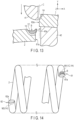
- FIG. 14 is a schematic side view of the coil spring 2 cut from the wire 1 by the method shown in FIG. 12 and FIG. 13 .
- the coil spring 2 has the first terminal 61 including the first end face 61a, and the second terminal 62 including the second end face 62a.
- the first end face 61a corresponds to the fracture surface of the coil spring 2 which is separated from the wire 1 in FIG. 13 .
- the first terminal 61 has the first irradiation trace M1 of laser light L, and the dent B of the cutter 41.
- the first irradiation trace M1 includes the quench hardened portion 1C and the heat affected portion (first heat affected portion) 1H.
- the second end face 62a corresponds to the fracture surface of the wire 1 which remains above the mandrel 42 when the coil spring 2 manufactured before the above coil spring 2 is separated.
- the second terminal 62 has the second irradiation trace M2 of laser light L.
- the second irradiation trace M2 includes the heat affected portion (second heat affected portion) 1H.
- the second irradiation trace M2 does not include the quench hardened portion 1C.
- the second irradiation trace M2 may include, for example, a less amount of quench hardened portion 1C than the first irradiation trace M1.
- FIG. 15 is a schematic plan view in which the surface of the wire 1 irradiated with laser light L1 having a rectangular beam profile as shown in FIG. 6 is viewed in the irradiation direction DL.
- a direction parallel to the axis of the wire 1 is referred to as an axial direction DA
- a direction orthogonal to the axial direction DA and the irradiation direction DL is referred to as the width direction DW of the wire 1.
- the dotted area in FIG. 15 corresponds to the irradiation area 1a irradiated with laser light L1 on the surface of the wire 1.
- the irradiation area 1a When viewed in the irradiation direction DL, the irradiation area 1a has a rectangular shape having width W1 in the axial direction DA and having width W2 in the width direction DW. Width W1 is less than width W2.
- the irradiation area 1a has a shape which is elongated in the width direction DW.
- FIG. 16 is a diagram for explaining the definition of the irradiation area 1a shown in FIG. 15.
- FIG. 16 shows center line CL1 which passes through the irradiation center O of the irradiation area 1a and is parallel to the axial direction DA, and center line CL2 which passes through the irradiation center O and is parallel to the width direction DW.
- laser light L1 On the surface of the wire 1, laser light L1 has output distribution PW1 along center line CL1, and output distribution PW2 along center line CL2.
- output distribution PW1 is a Gaussian output distribution
- output distribution PW2 is a top-hat output distribution
- the Gaussian output distribution PW1 has a mountain shape in which the output value reaches its peak in the center.
- the top-hat output distribution PW2 has a trapezoidal shape in which the peak of the output value covers a wide range.
- FIG. 17 is a schematic plan view in which the surface of the wire 1 irradiated with laser light L2 having a circular beam profile as shown in FIG. 8 is viewed in the irradiation direction DL.
- the irradiation area 1a is a circle having diameter Ra.
- FIG. 18 is a diagram for explaining the definition of the irradiation area 1a shown in FIG. 17 .
- laser light L2 has a Gaussian output distribution PW on the line segments which pass through the irradiation center O like center lines CL1 and CL2 on the surface of the wire 1.
- Diameter Ra corresponds to the half width of output distribution PW, in other words, the width of output distribution PW at the position where the output value becomes half of the peak PK.
- the irradiation area 1a irradiated with laser light L2 may be defined as a rectangular shape shown by width W1 in the axial direction DA and width W2 in the width direction DW in a manner similar to that of the example of FIG. 15 and FIG. 16 .
- both output distribution PW1 and output distribution PW2 may be a top-hat output distribution, or both output distribution PW1 and output distribution PW2 may be a Gaussian output distribution.
- output distribution PW may be a top-hat output distribution.
- the irradiation area 1a should be at least defined as an area irradiated with laser light L by an output which is greater than or equal to half of the peak.
- the shape of the irradiation area 1a is not limited to a rectangle or a circle. As another example, the irradiation area 1a may have an oval shape. In this case, the long axis and short axis of the irradiation area 1a may be defined by the half width of the output distribution.
- FIG. 19 is a chart showing irradiation conditions which may be applied to laser light L and implementation examples 1, 2 and 3.
- the cutting method using both heating by laser light L and the cutting unit 40 like the present embodiment is suitable for cutting a thick wire 1 whose diameter R is, for example, greater than or equal to 8 mm.
- the wire 1 is too thick, there is a possibility that a good cut surface cannot be obtained.
- the present embodiment assumes a case where diameter R of the wire 1 is greater than or equal to 8 mm and less than or equal to 18 mm as shown in the irradiation conditions of FIG. 19 .
- laser light L should be preferably emitted so as not to run off the wire 1. Further, if the irradiation area 1a irradiated with laser light L is too small, there is a possibility that a heat affected portion 1H having a shape suitable for cutting cannot be formed in the wire 1. In consideration of this matter, for example, when the irradiation area 1a has the rectangular shape shown in FIG. 15 and FIG.
- width W1 of the irradiation area 1a should be desirably greater than or equal to 2 mm and less than or equal to 6 mm
- width W2 should be desirably greater than or equal to 8 mm and less than or equal to 18 mm.
- the irradiation area is greater than or equal to 16 mm 2 and is less than or equal to 108 mm 2 .
- the output of laser light L needs to be determined such that a satisfactory heat affected portion 1H is formed in the wire 1, and further, the wire 1 is not cut by only irradiation with laser light L. If the output of laser light L is less, the irradiation time needs to be elongated to form a heat affected portion 1H which is sufficient for cutting. However, if the irradiation time is too long, the manufacturing efficiency of the coil spring 2 is decreased. If the output of laser light L is great, the size of the laser heater 30 is increased, and the degree of freedom of the layout of each unit of the coiling machine 100 is decreased. Further, there is a possibility that the size of the quench hardened portion 1C is increased as the wire 1 is overheated, and sputter occurs.
- the output of laser light L should be desirably greater than or equal to 500 W and less than or equal to 8000 W.
- the output density corresponding to the output of laser light L per unit area should be desirably greater than or equal to 10 W/mm 2 and less than or equal to 100 W/mm 2 .
- the output density should be more desirably greater than or equal to 31 W/mm 2 and less than or equal to 74 W/mm 2 .
- the output density is a value obtained by dividing the output of laser light L by the area of the irradiation area 1a on the surface of the wire 1 when viewed in the irradiation direction DL.
- the irradiation area 1a is an area defined by the half width of the output distribution of laser light L on the surface of the wire 1 as explained using, for example, FIG. 16 .
- the output of laser light L is 3000 W.
- the irradiation size and the irradiation area differ.
- the irradiation size is 4 mm ⁇ 14 mm in implementation example 1, 3.9 mm ⁇ 12.1 mm in implementation example 2, and 3.8 mm ⁇ 15.4 mm in implementation example 3.
- the irradiation area is 56 mm 2 in implementation example 1, 47.19 mm 2 in implementation example 2, and 58.52 mm 2 in implementation example 3.
- the output density is 53.57 W/mm 2 in implementation example 1, 63.57 W/mm 2 in implementation example 2, and 51.26 W/mm 2 in implementation example 3. All of these output densities are greater than or equal to 10 W/mm 2 and less than or equal to 100 W/mm 2 , and further, greater than or equal to 31 W/mm 2 and less than or equal to 74 W/mm 2 as shown in the irradiation conditions of FIG. 19 .
- FIG. 19 assumes a case where the irradiation size is defined by width W1 and width W2.
- the irradiation size may be defined by the radius.
- the irradiation size may be appropriately determined based on the shape of the irradiation area 1a. Even if the irradiation size is determined in any manner, similar effects can be obtained as long as the output density is in the range shown in FIG. 19 .
- the site (the heated site 1V) in which the temperature is increased by irradiation with laser light L is cut by the cutting unit 40 (the cutter 41 and the mandrel 42). Therefore, the shear force required for cutting becomes less. In this manner, the wire 1 can be easily cut.
- the manufacturing efficiency of the coil spring 2 can be improved, and further, the high-quality coil spring 2 having a good terminal can be obtained.
- the present invention can be implemented by modifying modes such as the configuration and layout of the elements provided in the coiling machine 100 in various ways depending on the need.
- Each embodiment exemplarily shows the configuration in which the coiling machine 100 cuts the heated site 1V of the wire 1 using the cutter 41.
- the coiling machine 100 is not limited to this configuration.
- the heated site 1V of the wire 1 may be cut by cutting using a rotary cutting blade.
- the coil spring 2 manufactured by the coiling machine 100 may be a coil spring in various forms, such as a cylindrical coil spring, a barrel-shaped coil spring, a hourglass coil spring, a tapered coil spring, a variable pitch coil spring and a coil spring having a portion with a minus pitch.
- Second terminal 100 ... Coiling machine, L, L1, L2 ... Laser light, S01 ... Helix formation process, S02 ... Heating process, S03 ... Cutting process, M1 ... First irradiation trace, M2 ... Second irradiation trace, B ... Dent, X ... Feed direction, Y ... Perpendicular direction, Z ... Formation direction, D ⁇ ... Circumferential direction, DL ... Irradiation direction
Landscapes
- Engineering & Computer Science (AREA)
- Mechanical Engineering (AREA)
- Physics & Mathematics (AREA)
- Optics & Photonics (AREA)
- Plasma & Fusion (AREA)
- Wire Processing (AREA)
Abstract
Description
- The present invention relates to a coiling machine for manufacturing a coil spring and a coil spring manufacturing method.
- As a device for manufacturing a coil spring, for example, the coil spring forming machine described in
patent literature 1 is known. This coil spring forming machine calculates the position of the cut site based on the length of a wire formed into a helical shape in advance and cuts the wire in a state where the cut site is softened by high-frequency heating. - Meanwhile like the spring manufacturing device described in
patent literature 2, a coiling machine which cuts a wire formed into a helical shape by laser light is also known. - In a case where high-frequency heating is used like the coil spring forming machine of
patent literature 1, the responsiveness of the heating of the cut site is not good. In addition, in the coil spring forming machine, as the wire is cut in a state where the hating of the cut site by high-frequency heating is continued, the members used for cutting may be affected by high-frequency heating. Further, in the coil spring forming machine, the responsiveness of high-frequency heating is not satisfactory, and the wire is coiled up in a state where the wire is partly heated. Therefore, it may be difficult to stabilize the formation accuracy of the spring. - On the other hand, the spring manufacturing device of
patent literature 2 requires high-power laser light which can cut a wire. In this case, sputter may occur because of irradiation with laser light, and further, laser light may be applied to each unit of the spring manufacturing device as well as the wire. Therefore, measures for these problems need to be taken. - In consideration of these matters, the applicant of the present application suggests the method of cutting a site of a wire heated by laser light by a cutting member such as a cutter as described in
patent literature 3. By this method, the wire can be easily cut, and further, a coil spring having a good cutting surface can be obtained. -
- Patent Literature 1:
JP S62-50028 A - Patent Literature 2:
JP H6-218476 A - Patent Literature 3:
JP 7066880 B - The method of cutting a site of a wire heated by laser light by a cutting member as described above has room for improvement in various ways. For example, the irradiation conditions of laser light for the wire need to be appropriately determined such that the wire is heated to a temperature which is suitable for cutting and further the section of the cut wire has a good shape.
- One of the objects of the present invention is to provide a coiling machine and a coil sprig manufacturing method for enabling the improvement of the manufacturing efficiency of a coil spring and the manufacturing of a coil spring having a good shape.
- The coiling machine of the present invention comprises a laser heater configured to emit laser light to a wire formed into a helical shape, thereby heating a portion of the wire, and a cutting unit configured to cut a site of the wire heated by irradiation with the laser light. An output density of the laser light is greater than or equal to 10 W/mm2 and less than or equal to 100 mm2.
- The coil spring manufacturing method of the present invention includes emitting laser light to a wire formed into a helical shape, thereby heating a portion of the wire, and cutting a site of the wire heated by irradiation with the laser light. An output density of the laser light is greater than or equal to 10 W/mm2 and less than or equal to 100 W/mm2.
- In each of the coiling machine and the manufacturing method, the output density should be desirably greater than or equal to 31 W/mm2 and less than or equal to 74 W/mm2.
- For example, the output density is a value obtained by dividing an output of the laser light by an area of an irradiation area irradiated with the laser light on a surface of the wire when viewed in an irradiation direction of the laser light. The irradiation area is an area defined by a half width of an output distribution of the laser light on the surface of the wire. The irradiation area may have a shape which is elongated in a width direction of the wire.
- For example, a diameter of the wire is greater than or equal to 8 mm and less than or equal to 18 mm. The area of the irradiation area is greater than or equal to 16 mm2 and less than or equal to 108 mm2. The output of the laser light is greater than or equal to 500 W and less than or equal to 8000 W.
- The present invention can provide a coiling machine and a coil spring manufacturing method for enabling the improvement of the manufacturing efficiency of a coil spring and the manufacturing of a coil spring having a good shape.
-
-
FIG. 1 is a schematic perspective view showing the main portions of a coiling machine according to an embodiment. -
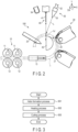
FIG. 2 is a schematic front view of the coiling machine according to the embodiment. -
FIG. 3 is a flowchart showing the operation of the coiling machine according to the embodiment. -
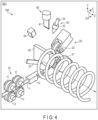
FIG. 4 is a schematic perspective view showing a specific example of a helix formation process by the coiling machine according to the embodiment. -
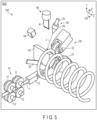
FIG. 5 is a schematic perspective view showing a specific example of a heating process by the coiling machine according to the embodiment. -
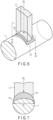
FIG. 6 is a perspective view showing the first example of the method of heating and softening a portion of a wire in a heating process. -
FIG. 7 is the cross-sectional view of the wire along the VII-VII line ofFIG. 6 . -
FIG. 8 is a perspective view showing the second example of the method of heating and softening a portion of the wire in a heating process. -
FIG. 9 is the cross-sectional view of the wire along the IX-IX line ofFIG. 8 . -
FIG. 10 is a schematic perspective view showing a specific example of a cutting process by the coiling machine according to the embodiment. -
FIG. 11 is a schematic cross-sectional view of the wire irradiated with laser light. -
FIG. 12 is a cross-sectional view showing an example of the preferable positional relationships of a cutter, a mandrel and the irradiation area irradiated with laser light. -
FIG. 13 is a cross-sectional view showing a state in which the cutter is moved downward from the state shown inFIG. 12 and the wire is cut. -
FIG. 14 is a schematic side view of the coil spring cut from the wire by the method shown inFIG. 12 andFIG. 13 . -
FIG. 15 is a schematic plan view in which the surface of the wire irradiated with laser light having a rectangular beam profile is viewed in an irradiation direction. -
FIG. 16 is a diagram for explaining the definition of the irradiation area shown inFIG. 15 . -
FIG. 17 is a schematic plan view in which the surface of the wire irradiated with laser light having a circular beam profile is viewed in the irradiation direction. -
FIG. 18 is a diagram for explaining the definition of the irradiation area shown inFIG. 17 . -
FIG. 19 is a chart showing irradiation conditions which may be applied to laser light and implementation examples. - Mode for Carrying Out the Invention Embodiments related to a coiling machine and a coil spring manufacturing method are hereinafter explained with reference to the accompanying drawings.
-
FIG. 1 is a schematic perspective view showing the main portions of acoiling machine 100 according to an embodiment.FIG. 2 is a schematic front view of thecoiling machine 100 shown inFIG. 1 . A feed direction X, a perpendicular direction Y, a formation direction Z and a circumferential direction Dθ are defined as shown inFIG. 1 andFIG. 2 . The feed direction X, the perpendicular direction Y and the formation direction Z are orthogonal to each other. The feed direction X is a direction in which alinear wire 1 before formation into a helical shape is fed. The formation direction Z is a direction in which a coil spring consisting of thewire 1 which is bent into a helical shape extends (a direction in which the spring develops). The circumferential direction Dθ is a direction in which thewire 1 constituting the coil spring is wound. - The coiling
machine 100 comprises afeed unit 10, ahelix formation unit 20, a heating unit (laser heater 30), a cuttingunit 40 and acontrol unit 50. - In the example of
FIG. 1 andFIG. 2 , thefeed unit 10 comprises a pair of drivingrollers 11, a pair of drivenrollers 12 and awire guide 13. Thefeed unit 10 may comprisemore driving rollers 11 and drivenrollers 12. - The driving
rollers 11 face the drivenrollers 12, respectively, via thewire 1. When each drivingroller 11 rotates, a corresponding drivenroller 12 rotates via thewire 1. In accordance with this rotation, thewire 1 interposed between the drivingrollers 11 and the drivenrollers 12 is fed in the feed direction X. Thewire 1 is inserted into thewire guide 13. Thewire guide 13 guides thewire 1 such that thewire 1 goes straight in the feed direction X, and guides thewire 1 to thehelix formation unit 20. - The
helix formation unit 20 forms thewire 1 fed by thefeed unit 10 into a helical shape. In the example ofFIG. 1 andFIG. 2 , thehelix formation unit 20 comprises afirst formation roller 21, asecond formation roller 22 and apitch tool 23. - The
first formation roller 21, thesecond formation roller 22 and thepitch tool 23 are provided in order in the circumferential direction Dθ. The positions of thefirst formation roller 21, thesecond formation roller 22 and thepitch tool 23 in the formation direction Z are different from each other. - The
first formation roller 21 and thesecond formation roller 22 bend, in the perpendicular direction Y, thewire 1 fed in the feed direction X in series. Thewire 1 which is bent in series in this manner draws an arc along the circumferential direction Dθ. Thebent wire 1 is guided by thepitch tool 23 at a position deviating in the formation direction Z relative to thesecond formation roller 22. - The
laser heater 30 emits laser light L to a portion of thewire 1 formed into a helical shape as shown inFIG. 2 . By this irradiation with laser light L, aheated site 1V in which the temperature is higher than the other portion is formed in thewire 1. - In the example of
FIG. 1 andFIG. 2 , thelaser heater 30 comprises alaser oscillator 31, anoptical fiber 32 and alaser head 33. Thelaser head 33 includes, for example, a beam spot adjustment device. - For the
laser oscillator 31, for example, a semiconductor laser which generates laser light L can be used. Theoptical fiber 32 transmits laser light L generated in thelaser oscillator 31 to thelaser head 33. Thelaser head 33 adjusts the beam shape of laser light L so as to be a rectangle or a circle by the beam spot adjustment device described above. For the beam spot adjustment device, for example, an optical element such as a beam homogenizer can be used. - The
laser heater 30 may further comprise ameasurement device 34 which measures the temperature of theheated site 1V. Themeasurement device 34 has, for example, a sensor which detects the temperature of theheated site 1V of thewire 1. Themeasurement device 34 may be provided on a lateral side of the cuttingunit 40 to avoid interference with the cuttingunit 40. Themeasurement device 34 may be configured to move away from acutter 41 in cooperation with the operation of thecutter 41 to avoid interference with thecutter 41 described later. The measurement result by themeasurement device 34 can be used to, for example, control the cut timing of thewire 1 by the cuttingunit 40. - It should be noted that the
measurement device 34 is not an essential configuration. In other words, without using themeasurement device 34, various conditions related to the cutting of thewire 1 may be set in advance, and the cuttingunit 40 may cut theheated site 1V based on the conditions. - The
laser heater 30 may further comprise a movement stage which causes thelaser head 33 to approach or move away from theheated site 1V of thewire 1. The movement stage may consist of, for example, a linear-motion stage or a robot hand. When the operation distance of thelaser head 33 can be set so as to be sufficiently long, and interference with the cuttingunit 40 can be avoided, the use of the movement stage is not necessary. - After the irradiation with laser light L is stopped, the cutting
unit 40 cuts theheated site 1V of thewire 1 having a temperature higher than that before the irradiation with the laser light. In the example ofFIG. 1 andFIG. 2 , the cuttingunit 40 comprises thecutter 41 and amandrel 42. - The
cutter 41 is provided between thesecond formation roller 22 and thepitch tool 23 in the circumferential direction Dθ. Thecutter 41 has, at the distal end, for example, a sharp cutting blade in which the blade edge is parallel to the formation direction Z. Thecutter 41 is configured such that it can be moved in the perpendicular direction Y by a drive mechanism (not shown). - The
mandrel 42 is provided on the inner side of thefirst formation roller 21, thesecond formation roller 22 and thepitch tool 23. For example, as shown inFIG. 2 , themandrel 42 has a semicircular shape along an X-Y plane, and extends so as to be elongated in the formation direction Z. Themandrel 42 supports the inner circumferential surface of thewire 1 formed into a helical shape mainly in the end portion of the arc surface in the perpendicular direction Y. - The
control unit 50 controls thefeed unit 10, thehelix formation unit 20, thelaser heater 30 and the cuttingunit 40. Thiscontrol unit 50 comprises acontroller 51. - The
controller 51 includes a read only memory (ROM), a central processing unit (CPU) and a random access memory (RAM). The ROM stores a computer program for controlling thefeed unit 10, thehelix formation unit 20, thelaser heater 30 and the cuttingunit 40. The CPU runs the computer program stored in the ROM. The RAM temporarily stores various types of data generated in association with the run of the computer program while the computer program is run by the CPU. - Now, this specification explains the manufacturing method of a
coil spring 2 using the coilingmachine 100 of the present embodiment with reference toFIG. 3 to FIG. 13 . -
FIG. 3 is a flowchart showing the operation of the coilingmachine 100. The operation shown in this flowchart is realized mainly as thecontroller 51 runs a computer program. The manufacturing process of thecoil spring 2 by the coilingmachine 100 includes a helix formation process S01, a heating process S02 and a cutting process S03. - In the helix formation process S01, the
wire 1 is formed into a helical shape. In the heating process S02 subsequent to the completion of the helix formation process S01, laser light L is emitted to a portion of thewire 1, thereby forming the heated site V1 in thewire 1. Theheated site 1V includes a portion which is softened relative to the other portion (base material) of thewire 1. In the cutting process S03 subsequent to the completion of the heating process S02, theheated site 1V of thewire 1 is cut. -
FIG. 4 is a schematic perspective view of the coilingmachine 100 and shows a specific example of the helix formation process S01. In the helix formation process S01, thefeed unit 10 guides thewire 1 to thewire guide 13 by causing thewire 1 to go straight in the feed direction X using the drivingrollers 11 and the drivenrollers 12. Thewire 1 drawn from thewire guide 13 is bent in the perpendicular direction Y by thefirst formation roller 21 and thesecond formation roller 22 and is formed into an arc shape. Thewire 1 formed into an arc shape is guided by thepitch tool 23 so as to be formed into a helical shape having a predetermined pitch. By this operation, thewire 1 having a helical shape gradually stretches in the formation direction Z. -
FIG. 5 is a schematic perspective view of the coilingmachine 100 and shows a specific example of the heating process S02. In the heating process S02, thelaser heater 30 directly emits laser light L to, for example, the portion located near the end portion of the mandrel 42 (under the cutter 41) in the perpendicular direction Y in thewire 1 formed into a helical shape. The base material of thewire 1 is heated by the energy of laser light L, and the softenedheated site 1V is formed. - When the heating process S02 is performed, the feeding of the
wire 1 by thefeed unit 10 is stopped. Thelaser heater 30 is provided at, for example, a predetermined position in a fixed manner, and emits laser light L to a portion of the suspendedwire 1 from that position. As another example, when thelaser heater 30 has the movement stage described above, thelaser heater 30 may move thelaser head 33 closer to thewire 1 and then emit laser light L. In the heating process S02, thelaser heater 30 may emit laser light L to the site of thewire 1 delivered in the circumferential direction Dθ without stopping the feeding of thewire 1 by thefeed unit 10. In this case, the movement of thelaser heater 30 may be controlled such that the irradiation position of laser light L is moved so as to follow the movement of the cut position by coiling. -
FIG. 6 is a perspective view of thewire 1 and shows the first example of the method of heating and softening a portion of thewire 1. In this example, thelaser heater 30 emits laser light L1 to the surface of thewire 1 in an irradiation direction DL. Laser light L1 has, for example, a rectangular beam profile which is elongated in the width direction of thewire 1. In theirradiation area 1a of thewire 1 irradiated with laser light L1 and its vicinity, theheated site 1V is formed. -
FIG. 7 is the cross-sectional view of thewire 1 along the VII-VII line ofFIG. 6 . Theheated site 1V extends to the inside of thewire 1 as well as the surrounding area of theirradiation area 1a on the surface of thewire 1. In the example of this figure, the width of laser light L1 is less than diameter R of thewire 1. Therefore, laser light L1 is mostly applied to thewire 1. -
FIG. 8 is a perspective view of thewire 1 and shows the second example of the method of heating and softening a portion of thewire 1. In this example, thelaser heater 30 emits laser light L2 to the surface of thewire 1 in the irradiation direction DL. Laser light L2 has, for example, a circular beam profile. In theirradiation area 1a of thewire 1 irradiated with this laser light L2 and its vicinity, theheated site 1V is formed in a manner similar to that of the first example. -
FIG. 9 is the cross-sectional view of thewire 1 along the IX-IX line ofFIG. 8 . Theheated site 1V extends to the inside of thewire 1 as well as the surrounding area of theirradiation area 1a on the surface of thewire 1. For example, the diameter of laser light L2 is less than diameter R of thewire 1. Therefore, laser light L2 is mostly applied to thewire 1. - The
heated site 1V may extend to the inside of thewire 1 more deeply than the examples shown inFIG. 7 andFIG. 9 . The shape of laser light L emitted by thelaser heater 30 is not limited to the first example and the second example. - In both the first example and the second example, the
heated site 1V may include a melt pool in which the base material of thewire 1 is melted by the energy of laser light L. The melt pool may extend to the surrounding area of theirradiation area 1a as well as theirradiation area 1a. -
FIG. 10 is a schematic perspective view of the coilingmachine 100 and shows a specific example of the cutting process S03. In this embodiment, the cutting process S03 is performed after the irradiation with laser light L is stopped. As another example, the cutting process S03 may be performed during the irradiation with laser light L. In the cutting process S03, theheated site 1V of thewire 1 in which the temperature is higher than that before the irradiation with laser light L is cut by the cuttingunit 40. By this process, thecoil spring 2 is manufactured. - Specifically, the
cutter 41 descends toward the vicinity of the portion of thewire 1 supported by themandrel 42 in the cutting process S03. At this time, thewire 1 is cut by the impact applied by thecutter 41. - In a case where the
heated site 1V includes a melt pool, the melt pool may solidify during the period from the suspension of irradiation with laser light L until the start of the operation of thecutter 41. The melt pool may be solidified as the heat of theheated site 1V is taken by thecutter 41 when thecutter 41 comes into contact with the surface of thewire 1 after the operation of thecutter 41. Thus, as the melt pool solidifies before or during the operation of thecutter 41, the attachment of melted metal to thecutter 41 can be prevented. - In the cutting process S03, the
cutter 41 may be operated based on the measurement result of the temperature of theheated site 1V by themeasurement device 34. Specifically, thecutter 41 may operate when the temperature of theheated site 1V is decreased to the predetermined target temperature after the irradiation with laser light L. The target temperature may be, for example, a temperature at which the melted base material solidifies. As a matter of course, in the cutting process S03, theheated site 1V may be cut without using themeasurement device 34 by determining in advance the delay time from the suspension of irradiation with laser light L until the start of the operation of thecutter 41. - The
cut coil spring 2 has afirst terminal 61 including afirst end face 61a, and asecond terminal 62 including asecond end face 62a. After onecoil spring 2 is manufactured, the helix formation process S01, heating process S02 and cutting process S03 described above are performed again, and thus, thenext coil spring 2 is manufactured. Thus, each of thefirst terminal 61 and thesecond terminal 62 is cut through the processes descried above. - A shear force necessary for cutting the
wire 1 decreases as the temperature of thewire 1 is increased by heating. Even if thewire 1 has not reached the melting point, the shear force can be decreased. Further, this tendency does not depend on the diameter of thewire 1. For example, when thewire 1 is cut by thecutter 41, the temperature of at least a portion of theheated site 1V should be desirably greater than or equal to 500°C. -
FIG. 11 is a schematic cross-sectional view of thewire 1 irradiated with laser light L. Here, this specification assumes a case where laser light L2 having the shape shown inFIG. 8 is emitted to the surface of thewire 1, and a melt pool is formed. In the figure, "O" indicates the center of theirradiation area 1a (seeFIG. 6 andFIG. 8 ) irradiated with laser light L on the outer circumferential surface of thewire 1. For example, this irradiation center O corresponds to the position at which the peak portion having the highest intensity is irradiated in the beam profile of laser light L. The irradiation center O may be considered as the center of the melt pool. - As described above, when the
wire 1 is irradiated with laser light L, theheated site 1V is formed. During the irradiation with laser light L or immediately after the irradiation, a melt pool is formed around the irradiation center O. By subsequent cooling, the melt pool is solidified, thereby forming a quenchhardened portion 1C. Around the melt pool, a heat affected portion (heat affected zone [HAZ]) 1H is formed. The heat affectedportion 1H has not been melted, but the property has been changed from the base material of thewire 1 by the heat applied at the time of the irradiation with laser light L. Thus, theheated site 1V includes the quenchhardened portion 1C and the heat affectedportion 1H. -
FIG. 11 shows the result obtained by measuring the Vickers hardness [HV] of the quenchhardened portion 1C, the heat affectedportion 1H and the base material of thewire 1. The quenchhardened portion 1C has a hardness which is greater than that of the base material as a whole. The heat affectedpotion 1H has a hardness which is less than that of the base material as a whole. The hardness of the heat affectedportion 1H gradually increases from the vicinity of the quenchhardened portion 1C to the base material. - Thus, similarly, the distribution of the hardness is nonuniform in the
heated site 1V. Therefore, the relationships between the positions of thecutter 41 and themandrel 42 and the irradiation area irradiated with laser light L need to be appropriately determined. -
FIG. 12 is a cross-sectional view showing an example of the preferable positional relationships of thecutter 41, themandrel 42 and the irradiation area irradiated with laser light L. In the helix formation process S01 described above, thewire 1 formed into a helical shape is delivered to the portion located between thecutter 41 and themandrel 42. In this delivering direction (circumferential direction Dθ) of thewire 1, a clearance G is provided between anend portion 41a of thecutter 41 and anend portion 42a of themandrel 42. Hereinafter, the center of the clearance G in the circumferential direction Dθ is referred to as a clearance center C. - In the example of
FIG. 12 , the clearance center C and the irradiation center O are out of alignment in the circumferential direction Dθ. Specifically, the irradiation center O is located on thecutter 41 side (the downstream side of the circumferential direction Dθ) relative to the clearance center C. - In the example of
FIG. 12 , theheated site 1V includes amelt pool 1P which becomes the quenchhardened portion 1C described above after solidification. For example, themelt pool 1P overlaps the clearance center C. Themelt pool 1P overlaps theend portion 41a of thecutter 41 in the perpendicular direction Y. - To the contrary, the
melt pool 1P does not overlap theend portion 42a of themandrel 42 in the perpendicular direction Y. In the example ofFIG. 12 , theend portion 42a of themandrel 42 overlaps, of the heat affectedportion 1H, the portion located on the upstream side of the circumferential direction Dθ relative to themelt pool 1P, in the perpendicular direction Y. -
FIG. 13 is a cross-sectional view showing a state in which thecutter 41 is moved downward from the state shown inFIG. 12 parallel to the perpendicular direction Y and thewire 1 is cut. As described above, when thewire 1 is cut by thecutter 41, themelt pool 1P has already solidified, or themelt pool 1P is solidified as the heat is taken by contact with thecutter 41. Thus, the quenchhardened portion 1C is formed during cutting. When cutting is performed, themelt pool 1P may partly remain inside theheated site 1V. - When the distal end portion of the
cutter 41 applies an impact to the outer circumferential surface of thewire 1 which protrudes from theend portion 42a of themandrel 42, a shear force is applied to theheated site 1V and its vicinity, and thus, thewire 1 is broken and cut. For example, thecutter 41 descends to the vicinity of the axis of thewire 1 at the maximum. In thecut wire 1, in other words, thecoil spring 2, a dent (recess portion) B by thecutter 41 is formed. In the example ofFIG. 13 , the quenchhardened portion 1C and the heat affectedportion 1H overlap the dent B. However, they may be misaligned with each other. - As described above, the heat affected
portion 1H is softer than the quenchhardened portion 1C and the base material of thewire 1. Therefore, when thecutter 41 applies an impact to thewire 1, the heat affectedportion 1H is easily broken and cut in theheated site 1V. In particular, if the irradiation center O is displaced on thecutter 41 side relative to the clearance center C as shown inFIG. 12 , a load can be effectively applied to, of the heat affectedportion 1H, the portion located on the upstream side of the circumferential direction Dθ relative to themelt pool 1P, and thus, thewire 1 can be broken and cut along this portion. -
FIG. 14 is a schematic side view of thecoil spring 2 cut from thewire 1 by the method shown inFIG. 12 andFIG. 13 . Thecoil spring 2 has thefirst terminal 61 including thefirst end face 61a, and thesecond terminal 62 including thesecond end face 62a. - The
first end face 61a corresponds to the fracture surface of thecoil spring 2 which is separated from thewire 1 inFIG. 13 . Thefirst terminal 61 has the first irradiation trace M1 of laser light L, and the dent B of thecutter 41. The first irradiation trace M1 includes the quenchhardened portion 1C and the heat affected portion (first heat affected portion) 1H. - The
second end face 62a corresponds to the fracture surface of thewire 1 which remains above themandrel 42 when thecoil spring 2 manufactured before theabove coil spring 2 is separated. Thesecond terminal 62 has the second irradiation trace M2 of laser light L. The second irradiation trace M2 includes the heat affected portion (second heat affected portion) 1H. When thewire 1 is cut as shown inFIG. 13 , the second irradiation trace M2 does not include the quenchhardened portion 1C. However, the second irradiation trace M2 may include, for example, a less amount of quenchhardened portion 1C than the first irradiation trace M1. - The heat affected
portion 1H included in the first irradiation trace M1 extends to at least a portion of thefirst end face 61a. The heat affectedportion 1H included in the second irradiation trace M2 extends to at least a portion of thesecond end face 62a. To the contrary, the quenchhardened portion 1C included in the first irradiation trace M1 does not extend to thefirst end face 61a. It should be noted that a portion of the quenchhardened portion 1C may extend to thefirst end face 61a. In this case, on thefirst end face 61a, the area of the quenchhardened portion 1C should be desirably less than that of the heat affectedportion 1H. - Now, this specification explains the irradiation conditions of laser light L.
-
FIG. 15 is a schematic plan view in which the surface of thewire 1 irradiated with laser light L1 having a rectangular beam profile as shown inFIG. 6 is viewed in the irradiation direction DL. In the following explanation, a direction parallel to the axis of thewire 1 is referred to as an axial direction DA, and a direction orthogonal to the axial direction DA and the irradiation direction DL is referred to as the width direction DW of thewire 1. - The dotted area in
FIG. 15 corresponds to theirradiation area 1a irradiated with laser light L1 on the surface of thewire 1. When viewed in the irradiation direction DL, theirradiation area 1a has a rectangular shape having width W1 in the axial direction DA and having width W2 in the width direction DW. Width W1 is less than width W2. Thus, in the example ofFIG. 15 , theirradiation area 1a has a shape which is elongated in the width direction DW. -
FIG. 16 is a diagram for explaining the definition of theirradiation area 1a shown inFIG. 15. FIG. 16 shows center line CL1 which passes through the irradiation center O of theirradiation area 1a and is parallel to the axial direction DA, and center line CL2 which passes through the irradiation center O and is parallel to the width direction DW. On the surface of thewire 1, laser light L1 has output distribution PW1 along center line CL1, and output distribution PW2 along center line CL2. - In the example of
FIG. 16 , output distribution PW1 is a Gaussian output distribution, and output distribution PW2 is a top-hat output distribution. The Gaussian output distribution PW1 has a mountain shape in which the output value reaches its peak in the center. The top-hat output distribution PW2 has a trapezoidal shape in which the peak of the output value covers a wide range. - In the present embodiment, the half width in output distribution PW1 is defined as width W1, and the half width in output distribution PW2 is defined as width W2. It should be noted that the half width of the Gaussian output distribution PW1 corresponds to the width of output distribution PW1 at the position where the output value becomes half of the peak PK. Similarly, the half width of the top-hat output distribution PW2 corresponds to the width of output distribution PW2 at the position where the output value becomes half of the peak. The half width of the top-hat output distribution PW2 can be also considered as a value obtained by adding the bottom length Wb and top length Wt of output distribution PW2 and multiplying it by 1/2.
-
FIG. 17 is a schematic plan view in which the surface of thewire 1 irradiated with laser light L2 having a circular beam profile as shown inFIG. 8 is viewed in the irradiation direction DL. In the example ofFIG. 17 , theirradiation area 1a is a circle having diameter Ra. -
FIG. 18 is a diagram for explaining the definition of theirradiation area 1a shown inFIG. 17 . For example, laser light L2 has a Gaussian output distribution PW on the line segments which pass through the irradiation center O like center lines CL1 and CL2 on the surface of thewire 1. Diameter Ra corresponds to the half width of output distribution PW, in other words, the width of output distribution PW at the position where the output value becomes half of the peak PK. - It should be noted that the
irradiation area 1a irradiated with laser light L2 may be defined as a rectangular shape shown by width W1 in the axial direction DA and width W2 in the width direction DW in a manner similar to that of the example ofFIG. 15 and FIG. 16 . - The shape of the
irradiation area 1a or the output distribution of laser light L1 or L2 is not limited to the examples shown by usingFIG. 15 to FIG. 18 . For example, inFIG. 15 and FIG. 16 , both output distribution PW1 and output distribution PW2 may be a top-hat output distribution, or both output distribution PW1 and output distribution PW2 may be a Gaussian output distribution. In the example ofFIG. 17 and FIG. 18 , output distribution PW may be a top-hat output distribution. - The
irradiation area 1a should be at least defined as an area irradiated with laser light L by an output which is greater than or equal to half of the peak. The shape of theirradiation area 1a is not limited to a rectangle or a circle. As another example, theirradiation area 1a may have an oval shape. In this case, the long axis and short axis of theirradiation area 1a may be defined by the half width of the output distribution. -
FIG. 19 is a chart showing irradiation conditions which may be applied to laser light L and implementation examples 1, 2 and 3. The cutting method using both heating by laser light L and the cuttingunit 40 like the present embodiment is suitable for cutting athick wire 1 whose diameter R is, for example, greater than or equal to 8 mm. However, if thewire 1 is too thick, there is a possibility that a good cut surface cannot be obtained. In light of this matter, for example, the present embodiment assumes a case where diameter R of thewire 1 is greater than or equal to 8 mm and less than or equal to 18 mm as shown in the irradiation conditions ofFIG. 19 . - In consideration of the heating efficiency, laser light L should be preferably emitted so as not to run off the
wire 1. Further, if theirradiation area 1a irradiated with laser light L is too small, there is a possibility that a heat affectedportion 1H having a shape suitable for cutting cannot be formed in thewire 1. In consideration of this matter, for example, when theirradiation area 1a has the rectangular shape shown inFIG. 15 and FIG. 16 , and diameter R of thewire 1 is greater than or equal to 8 mm and less than or equal to 18 mm, width W1 of theirradiation area 1a should be desirably greater than or equal to 2 mm and less than or equal to 6 mm, and width W2 should be desirably greater than or equal to 8 mm and less than or equal to 18 mm. In case of this irradiation size, the irradiation area (width W1 × width W2) is greater than or equal to 16 mm2 and is less than or equal to 108 mm2. - The output of laser light L needs to be determined such that a satisfactory heat affected
portion 1H is formed in thewire 1, and further, thewire 1 is not cut by only irradiation with laser light L. If the output of laser light L is less, the irradiation time needs to be elongated to form a heat affectedportion 1H which is sufficient for cutting. However, if the irradiation time is too long, the manufacturing efficiency of thecoil spring 2 is decreased. If the output of laser light L is great, the size of thelaser heater 30 is increased, and the degree of freedom of the layout of each unit of the coilingmachine 100 is decreased. Further, there is a possibility that the size of the quenchhardened portion 1C is increased as thewire 1 is overheated, and sputter occurs. - For example, in consideration of these matters, the output of laser light L should be desirably greater than or equal to 500 W and less than or equal to 8000 W. The output density corresponding to the output of laser light L per unit area should be desirably greater than or equal to 10 W/mm2 and less than or equal to 100 W/mm2. The output density should be more desirably greater than or equal to 31 W/mm2 and less than or equal to 74 W/mm2.
- It should be noted that the output density is a value obtained by dividing the output of laser light L by the area of the
irradiation area 1a on the surface of thewire 1 when viewed in the irradiation direction DL. Here, theirradiation area 1a is an area defined by the half width of the output distribution of laser light L on the surface of thewire 1 as explained using, for example,FIG. 16 . - In all of implementation examples 1, 2 and 3 shown in
FIG. 19 , the output of laser light L is 3000 W. However, the irradiation size and the irradiation area differ. The irradiation size is 4 mm × 14 mm in implementation example 1, 3.9 mm × 12.1 mm in implementation example 2, and 3.8 mm × 15.4 mm in implementation example 3. The irradiation area is 56 mm2 in implementation example 1, 47.19 mm2 in implementation example 2, and 58.52 mm2 in implementation example 3. - In this case, the output density is 53.57 W/mm2 in implementation example 1, 63.57 W/mm2 in implementation example 2, and 51.26 W/mm2 in implementation example 3. All of these output densities are greater than or equal to 10 W/mm2 and less than or equal to 100 W/mm2, and further, greater than or equal to 31 W/mm2 and less than or equal to 74 W/mm2 as shown in the irradiation conditions of
FIG. 19 . - To manufacture a
coil spring 2 by the coilingmachine 100 using awire 1 whose diameter R is greater than or equal to 8 mm and less than or equal to 18 mm, when laser light L to which the conditions of implementation examples 1, 2 and 3 are applied was used in the heating process S02, the shear force required for cutting was less, and acoil spring 2 having a good terminal shape was manufactured. -
FIG. 19 assumes a case where the irradiation size is defined by width W1 and width W2. However, when theirradiation area 1a is circular, the irradiation size may be defined by the radius. In addition, the irradiation size may be appropriately determined based on the shape of theirradiation area 1a. Even if the irradiation size is determined in any manner, similar effects can be obtained as long as the output density is in the range shown inFIG. 19 . - In the embodiment described above, of the
wire 1 which is bent into a helical shape, the site (theheated site 1V) in which the temperature is increased by irradiation with laser light L is cut by the cutting unit 40 (thecutter 41 and the mandrel 42). Therefore, the shear force required for cutting becomes less. In this manner, thewire 1 can be easily cut. - Further, when the irradiation conditions of laser light L such as the output density are determined as explained using
FIG. 19 , the manufacturing efficiency of thecoil spring 2 can be improved, and further, the high-quality coil spring 2 having a good terminal can be obtained. - The embodiment described above does not limit the scope of the present invention to the configuration disclosed in the embodiment. The present invention can be implemented by modifying the configuration disclosed in the embodiment in various ways.
- For example, as a matter of course, the present invention can be implemented by modifying modes such as the configuration and layout of the elements provided in the coiling
machine 100 in various ways depending on the need. - Each embodiment exemplarily shows the configuration in which the coiling
machine 100 cuts theheated site 1V of thewire 1 using thecutter 41. The coilingmachine 100 is not limited to this configuration. Theheated site 1V of thewire 1 may be cut by cutting using a rotary cutting blade. - There are various forms for the
coil spring 2 manufactured by the coilingmachine 100. For example, the coil diameter and the pitch may be changed in the axial direction of the coil spring. In other words, thecoil spring 2 manufactured by the coilingmachine 100 may be a coil spring in various forms, such as a cylindrical coil spring, a barrel-shaped coil spring, a hourglass coil spring, a tapered coil spring, a variable pitch coil spring and a coil spring having a portion with a minus pitch. - 1 ... Wire, 1a ... Irradiation area, 1V ... Heated site, 1P ... Melt pool, 1C ... Quench hardened portion, 1H ... Heat affected portion, 2 ... Coil spring, 10 ... Feed unit, 11 ... Driving roller, 12 ... Driven roller, 13 ... Wire guide, 20 ... Helix formation unit, 21 ... First formation roller, 22 ... Second formation roller, 23 ... Pitch tool, 30 ... Laser heater, 31 ... Laser oscillator, 32 ... Optical fiber, 33 ... Laser head, 34 ... Measurement device, 40 ... Cutting unit, 41 ... Cutter, 42 ... Mandrel, 50 ... Control unit, 51 ... Controller, 61 ... First terminal, 62 ... Second terminal, 100 ... Coiling machine, L, L1, L2 ... Laser light, S01 ... Helix formation process, S02 ... Heating process, S03 ... Cutting process, M1 ... First irradiation trace, M2 ... Second irradiation trace, B ... Dent, X ... Feed direction, Y ... Perpendicular direction, Z ... Formation direction, Dθ ... Circumferential direction, DL ... Irradiation direction
Claims (12)
- A coiling machine comprising:a laser heater configured to emit laser light to a wire formed into a helical shape, thereby heating a portion of the wire; anda cutting unit configured to cut a site of the wire heated by irradiation with the laser light, whereinan output density of the laser light is greater than or equal to 10 W/mm2 and less than or equal to 100 W/mm2.
- The coiling machine of claim 1, wherein
the output density is greater than or equal to 31 W/mm2 and less than or equal to 74 W/mm2. - The coiling machine of claim 1, wherein
the output density is a value obtained by dividing an output of the laser light by an area of an irradiation area irradiated with the laser light on a surface of the wire when viewed in an irradiation direction of the laser light. - The coiling machine of claim 3, wherein
the irradiation area is an area defined by a half width of an output distribution of the laser light on the surface of the wire. - The coiling machine of claim 4, wherein
the irradiation area has a shape which is elongated in a width direction of the wire. - The coiling machine of one of claims 3 to 5, whereina diameter of the wire is greater than or equal to 8 mm and less than or equal to 18 mm,the area of the irradiation area is greater than or equal to 16 mm2 and less than or equal to 108 mm2, andthe output of the laser light is greater than or equal to 500 W and less than or equal to 8000 W.
- A coil spring manufacturing method including:emitting laser light to a wire formed into a helical shape, thereby heating a portion of the wire; andcutting a site of the wire heated by irradiation with the laser light, whereinan output density of the laser light is greater than or equal to 10 W/mm2 and less than or equal to 100 W/mm2.
- The coil spring manufacturing method of claim 7, wherein
the output density is greater than or equal to 31 W/mm2 and less than or equal to 74 W/mm2. - The coil spring manufacturing method of claim 7, wherein
the output density is a value obtained by diving an output of the laser light by an area of an irradiation area irradiated with the laser light on a surface of the wire when viewed in an irradiation direction of the laser light. - The coil spring manufacturing method of claim 9, wherein
the irradiation area is an area defined by a half width of an output distribution of the laser light on the surface of the wire. - The coil spring manufacturing method of claim 10, wherein
the irradiation area has a shape which is elongated in a width direction of the wire. - The coil spring manufacturing method of one of claims 9 to 11, whereina diameter of the wire is greater than or equal to 8 mm and less than or equal to 18 mm,the area of the irradiation area is greater than or equal to 16 mm2 and less than or equal to 108 mm2, andthe output of the laser light is greater than or equal to 500 W and less than or equal to 8000 W.
Applications Claiming Priority (2)
| Application Number | Priority Date | Filing Date | Title |
|---|---|---|---|
| JP2022129256A JP7840815B2 (en) | 2022-08-15 | 2022-08-15 | Coiling machine and method for manufacturing coil springs |
| PCT/JP2023/022577 WO2024038669A1 (en) | 2022-08-15 | 2023-06-19 | Coiling machine and production method for coil springs |
Publications (2)
| Publication Number | Publication Date |
|---|---|
| EP4574299A1 true EP4574299A1 (en) | 2025-06-25 |
| EP4574299A4 EP4574299A4 (en) | 2025-12-17 |
Family
ID=89941432
Family Applications (1)
| Application Number | Title | Priority Date | Filing Date |
|---|---|---|---|
| EP23854707.9A Pending EP4574299A4 (en) | 2022-08-15 | 2023-06-19 | WINDING MACHINE AND MANUFACTURING PROCESS FOR SCREW SPRINGS |
Country Status (6)
| Country | Link |
|---|---|
| US (1) | US20250178069A1 (en) |
| EP (1) | EP4574299A4 (en) |
| JP (1) | JP7840815B2 (en) |
| CN (1) | CN119677602A (en) |
| MX (1) | MX2025001806A (en) |
| WO (1) | WO2024038669A1 (en) |
Families Citing this family (2)
| Publication number | Priority date | Publication date | Assignee | Title |
|---|---|---|---|---|
| JP7203910B1 (en) * | 2021-07-01 | 2023-01-13 | 日本発條株式会社 | Coil spring, suspension, and method for manufacturing coil spring |
| JP7749872B1 (en) * | 2025-04-10 | 2025-10-06 | 日本発條株式会社 | Coiling machine and coil spring manufacturing method |
Family Cites Families (7)
| Publication number | Priority date | Publication date | Assignee | Title |
|---|---|---|---|---|
| JPS59187414A (en) * | 1983-04-08 | 1984-10-24 | Mitsubishi Electric Corp | Shearing machine additionally using laser |
| JPS6250028A (en) * | 1985-08-27 | 1987-03-04 | High Frequency Heattreat Co Ltd | Cutting method at forming cold formed coil spring of high strength and thick diameter wire |
| JPS63260716A (en) * | 1987-04-20 | 1988-10-27 | Nippon Steel Corp | Method for reducing burrs generated in shearing of steel sheet |
| JPH0729164B2 (en) * | 1993-01-27 | 1995-04-05 | 株式会社板屋製作所 | Spring manufacturing equipment |
| DE102013214161B4 (en) * | 2013-07-18 | 2015-05-07 | Wafios Ag | Method and device for producing coil springs by spring winds |
| JP7258545B2 (en) * | 2018-12-28 | 2023-04-17 | 日本発條株式会社 | Coiling machine and manufacturing method of coil spring |
| HUE070750T2 (en) * | 2019-02-06 | 2025-07-28 | Nhk Spring Co Ltd | Coiling machine, method for manufacturing coil spring, and coil spring |
-
2022
- 2022-08-15 JP JP2022129256A patent/JP7840815B2/en active Active
-
2023
- 2023-06-19 WO PCT/JP2023/022577 patent/WO2024038669A1/en not_active Ceased
- 2023-06-19 CN CN202380058832.6A patent/CN119677602A/en active Pending
- 2023-06-19 EP EP23854707.9A patent/EP4574299A4/en active Pending
-
2025
- 2025-02-10 US US19/049,752 patent/US20250178069A1/en active Pending
- 2025-02-12 MX MX2025001806A patent/MX2025001806A/en unknown
Also Published As
| Publication number | Publication date |
|---|---|
| CN119677602A (en) | 2025-03-21 |
| US20250178069A1 (en) | 2025-06-05 |
| JP7840815B2 (en) | 2026-04-06 |
| EP4574299A4 (en) | 2025-12-17 |
| JP2024025901A (en) | 2024-02-28 |
| MX2025001806A (en) | 2025-03-07 |
| WO2024038669A1 (en) | 2024-02-22 |
Similar Documents
| Publication | Publication Date | Title |
|---|---|---|
| US20250178069A1 (en) | Coiling machine and production method for coil springs | |
| EP3922377B1 (en) | Coiling machine, method for manufacturing coil spring, and coil spring | |
| US20250178068A1 (en) | Coiling machine and coil spring manufacturing method | |
| US11502587B2 (en) | Method and apparatus for manufacturing a stator of a dynamo-electric machine | |
| CN105377466B (en) | Method and device for producing helical springs by winding springs | |
| EP3766629A1 (en) | Cutting machine and cutting method | |
| EP3766630B1 (en) | Laser processing machine and laser processing method | |
| US10478922B2 (en) | Wire-based additive manufacturing system and method | |
| US6365870B1 (en) | Method and device for treating work pieces with laser radiation | |
| EP3871825B1 (en) | Laser beam machine, laser beam machining method | |
| US12533730B2 (en) | Additive manufacturing apparatus and additive manufacturing method | |
| US20230105729A1 (en) | Press-Forming Device for Depositing Solder and Producing Individual Solder Bodies | |
| US20220032401A1 (en) | Laser processing method, laser processing device, and method for producing laser processed product | |
| JP7749872B1 (en) | Coiling machine and coil spring manufacturing method | |
| US20250187118A1 (en) | Dynamically controlled laser drilling system and method for producing holes | |
| KR20170124101A (en) | Method for producing a tube from metal | |
| WO1999036200A1 (en) | A welding method, a heat exchanger tube, and an apparatus for the manufacturing of a heat exchanger tube | |
| EP4501526A1 (en) | Laser piercing method, and laser machine |
Legal Events
| Date | Code | Title | Description |
|---|---|---|---|
| STAA | Information on the status of an ep patent application or granted ep patent |
Free format text: STATUS: THE INTERNATIONAL PUBLICATION HAS BEEN MADE |
|
| PUAI | Public reference made under article 153(3) epc to a published international application that has entered the european phase |
Free format text: ORIGINAL CODE: 0009012 |
|
| STAA | Information on the status of an ep patent application or granted ep patent |
Free format text: STATUS: REQUEST FOR EXAMINATION WAS MADE |
|
| 17P | Request for examination filed |
Effective date: 20250210 |
|
| AK | Designated contracting states |
Kind code of ref document: A1 Designated state(s): AL AT BE BG CH CY CZ DE DK EE ES FI FR GB GR HR HU IE IS IT LI LT LU LV MC ME MK MT NL NO PL PT RO RS SE SI SK SM TR |
|
| DAV | Request for validation of the european patent (deleted) | ||
| DAX | Request for extension of the european patent (deleted) | ||
| A4 | Supplementary search report drawn up and despatched |
Effective date: 20251118 |
|
| RIC1 | Information provided on ipc code assigned before grant |
Ipc: B21F 35/00 20060101AFI20251112BHEP Ipc: B21F 11/00 20060101ALI20251112BHEP |