EP4574003A1 - A heat pump dishwasher and the control method thereof - Google Patents
A heat pump dishwasher and the control method thereof Download PDFInfo
- Publication number
- EP4574003A1 EP4574003A1 EP24201955.2A EP24201955A EP4574003A1 EP 4574003 A1 EP4574003 A1 EP 4574003A1 EP 24201955 A EP24201955 A EP 24201955A EP 4574003 A1 EP4574003 A1 EP 4574003A1
- Authority
- EP
- European Patent Office
- Prior art keywords
- discharge
- receptacle
- pump
- water
- evaporator
- Prior art date
- Legal status (The legal status is an assumption and is not a legal conclusion. Google has not performed a legal analysis and makes no representation as to the accuracy of the status listed.)
- Withdrawn
Links
Images

Classifications
-
- A—HUMAN NECESSITIES
- A47—FURNITURE; DOMESTIC ARTICLES OR APPLIANCES; COFFEE MILLS; SPICE MILLS; SUCTION CLEANERS IN GENERAL
- A47L—DOMESTIC WASHING OR CLEANING; SUCTION CLEANERS IN GENERAL
- A47L15/00—Washing or rinsing machines for crockery or tableware
- A47L15/42—Details
- A47L15/4291—Recovery arrangements, e.g. for the recovery of energy or water
-
- A—HUMAN NECESSITIES
- A47—FURNITURE; DOMESTIC ARTICLES OR APPLIANCES; COFFEE MILLS; SPICE MILLS; SUCTION CLEANERS IN GENERAL
- A47L—DOMESTIC WASHING OR CLEANING; SUCTION CLEANERS IN GENERAL
- A47L15/00—Washing or rinsing machines for crockery or tableware
- A47L15/42—Details
- A47L15/4214—Water supply, recirculation or discharge arrangements; Devices therefor
- A47L15/4223—Devices for water discharge, e.g. devices to prevent siphoning, non-return valves
-
- A—HUMAN NECESSITIES
- A47—FURNITURE; DOMESTIC ARTICLES OR APPLIANCES; COFFEE MILLS; SPICE MILLS; SUCTION CLEANERS IN GENERAL
- A47L—DOMESTIC WASHING OR CLEANING; SUCTION CLEANERS IN GENERAL
- A47L15/00—Washing or rinsing machines for crockery or tableware
- A47L15/42—Details
- A47L15/4214—Water supply, recirculation or discharge arrangements; Devices therefor
- A47L15/4225—Arrangements or adaption of recirculation or discharge pumps
-
- A—HUMAN NECESSITIES
- A47—FURNITURE; DOMESTIC ARTICLES OR APPLIANCES; COFFEE MILLS; SPICE MILLS; SUCTION CLEANERS IN GENERAL
- A47L—DOMESTIC WASHING OR CLEANING; SUCTION CLEANERS IN GENERAL
- A47L15/00—Washing or rinsing machines for crockery or tableware
- A47L15/42—Details
- A47L15/4285—Water-heater arrangements
Definitions
- the present invention relates to a heat pump dishwasher wherein the water condensed in the evaporator is discharged, and to the control method thereof.
- a heat pump dishwasher comprises a compressor, a condenser, a capillary tube and an evaporator, and forms a refrigerant fluid cycle.
- the high temperature refrigerant fluid leaving the compressor is sent to the condenser and a hot surface is formed on the evaporator.
- the water is passed over or through the condenser by means of a circulation pump to be heated, and then sent to the dishwasher by means of a multi-way valve.
- the refrigerant fluid is passed through the capillary tube such that the pressure and therefore temperature thereof are suddenly reduced before being sent to the evaporator.
- the refrigerant fluid cycle by means of two fans disposed in front of the evaporator, the air in the casing volume where the heat pump is positioned is sucked and blown into the evaporator. Heat transfer occurs to the evaporator, which is the cold surface, from the environment where the same is disposed. Finally, the refrigerant fluid returns to the suction line of the compressor, and the refrigerant fluid cycle is completed.
- the condensate is collected in the receptacle under the evaporator.
- an additional pump is used to discharge the water collected in the receptacle.
- the condensate is discharged by means of the additional pump operated at certain steps of the refrigerant fluid cycle.
- the additional pump is operated at least twice in a cycle and noise which can be easily heard from outside is generated during the refrigerant fluid cycle.
- the efficiency is decreased and the costs are increased. Furthermore, the water which condenses and accumulates in the receptacle under the evaporator if the additional pump is blocked overflows or activates the overflow safety device, causing the dishwasher to give a water leakage error.
- German Patent Application No. DE102012105670 a dishwasher is disclosed, wherein the heat pump is used in the drying process.
- a dishwasher wherein the water in the evaporator receptacle is discharged by means of a sensor measuring the amount of water in the evaporator receptacle, a circulation pump, and a valve connected to the latter.
- the aim of the present invention is the realization of a heat pump dishwasher wherein the water condensed in the evaporator is discharged, and of the control method thereof.
- the heat pump dishwasher realized in order to attain the aim of the present invention, explicated in the first claim and the respective claims thereof, comprises a discharge hose which is disposed between the condensation receptacle and the discharge pump, one end of which is connected to the condensation receptacle and the other end to the discharge pump, and which enables the water in the condensation receptacle to be sucked and discharged when the discharge pump is operated.
- the washing water is collected in the washing water receptacle in the heat pump dishwasher.
- the washing water is taken from the washing water receptacle by means of the circulation pump and passed over the condenser in the heat pump, and then, the washing water heated by means of the condenser is transferred to the tub.
- the discharge pump When the discharge pump is operated, negative pressure occurs in the discharge hose, one end of which is connected to the condensation receptacle and the other end to the discharge pump, and the water in the condensation receptacle is sucked towards the discharge pump. The water reaching the discharge pump is discharged together with the water leaving the washing process.
- the discharge hose is disposed between the condensation receptacle under the evaporator and the discharge pump, and is directly connected to the inlet of the discharge pump.
- negative pressure occurs in the discharge hose, and the water collected in the condensation receptacle is sucked from the end of the discharge hose connected to the condensation receptacle to be delivered to the discharge pump and discharged together with the discharged water.
- a preferably one-way valve disposed on the discharge hose provides that there is no backpressure in the discharge hose.
- the discharge hose is connected to the discharge pump at an angle of 45°, 60° or 90°.
- the water in the condensation receptacle is enabled to be discharged without the need for the use of an additional pump, valve or sensor.
- the need for using components requiring control such as additional pump, valve and/or sensor is eliminated, saving costs.
- the additional noise source in the current embodiment is eliminated, the perception of quality is increased.
- the heat pump dishwasher (1) comprises a tub (2) wherein the dishes are placed; a washing water receptacle (3) which is disposed under the tub (2); a circulation pump (4) which is connected to the washing water receptacle (3) and which provides the transfer of the washing water to the tub (2); a discharge pump (5) which is connected to the washing water receptacle (3) and which provides the discharge of the dirt water; a heat pump (6) which is disposed under the tub (2) and which has at least one compressor (8), at least one evaporator (9), at least one condenser (7) and at least one capillary tube (10) which are connected to each other by means of a refrigerant fluid line through which the refrigerant fluid is circulated; a condensation receptacle (11) which is disposed under the evaporator (9) and wherein the water condensed in the evaporator (9) is collected; and a discharge hose (12) which is disposed between the condensation receptacle (11) and the discharge pump (5), one end of which is
- the washing water is collected in the washing water receptacle (3) in the heat pump dishwasher (1).
- the washing water is taken from the washing water receptacle (3) by means of the circulation pump (4) and passed over the condenser (7) in the heat pump (6), and then, the washing water heated by means of the condenser (7) is transferred to the tub (2).
- the heat pump (6) operates as follows:
- the compressor (8) pressurizes the refrigerant fluid and sends the same to the condenser (7).
- the pressure and hence the temperature of the refrigerant fluid increase.
- the condenser (7) is heated.
- the water taken from the washing water receptacle (3) by means of the circulation pump (4) is passed over the condenser (7) and the washing water is heated.
- the refrigerant fluid leaving the condenser (7) is directed to the capillary tube (10) and the pressure and hence the temperature of the refrigerant fluid are reduced.
- the refrigerant fluid leaving the capillary tube (10) is sent to the evaporator (9). Since the evaporator (9) is air sourced, the air passing over the evaporator (9) is moved away from the dishwasher (1) and sent to the environment, and thus heat transfer is performed from the environment to the evaporator (9).
- the refrigerant fluid leaving the evaporator (9) is sucked again by the compressor (8) and the refrigerant fluid cycle is completed. Since the temperature of the ambient air passing over the evaporator (9) is much higher than the surface temperature of the evaporator (9) and the surface temperature of the evaporator (9) is below the dew point temperature of the air, the air is dehumidified and condensed on the surface of the evaporator (9). The water droplets condensing on the surface of the evaporator (9) are collected in the condensation receptacle (11) disposed under the evaporator (9).
- the discharge hose (12) is disposed between the condensation receptacle (11) under the evaporator (9) and the discharge pump (5), and is directly connected to the inlet of the discharge pump (5).
- negative pressure occurs in the discharge hose (12)
- the water collected in the condensation receptacle (11) is sucked from the end of the discharge hose (12) connected to the condensation receptacle (11) to be delivered to the discharge pump (5) and discharged together with the discharged water.
- the dishwasher (1) comprises a valve (13) disposed on the discharge hose (12).
- the valve (13) is a one-way valve.
- the valve (13) enables the water sucked from the condensation receptacle (11) to flow towards the discharge pump (5) and prevents the water from returning to the condensation receptacle (11) through the discharge hose (12). Thus, any backpressure in the discharge hose (12) is prevented.
- the dishwasher (1) comprises the discharge hose (12) which is connected to the discharge pump (5) at a 45° angle.
- the discharge hose (12) is connected to the discharge pump (5) at a 60° angle.
- the discharge hose (12) is connected to the discharge pump (5) at an angle of 90°.
- the water in the condensation receptacle (11) is enabled to be discharged without the need for the use of an additional pump, valve or sensor.
- the need for using components requiring control such as additional pump, valve and/or sensor is eliminated, saving costs.
- the additional noise source in the current embodiment is eliminated, the perception of quality is increased.
Landscapes
- Washing And Drying Of Tableware (AREA)
Abstract
The present invention relates to a heat pump dishwasher (1) comprising a tub (2) wherein the dishes are placed; a washing water receptacle (3) which is disposed under the tub (2); a circulation pump (4) which is connected to the washing water receptacle (3) and which provides the transfer of the washing water to the tub (2); a discharge pump (5) which is connected to the washing water receptacle (3) and which provides the discharge of the dirt water; a heat pump (6) which is disposed under the tub (2) and which has at least one compressor (8), at least one evaporator (9), at least one condenser (7) and at least one capillary tube (10) which are connected to each other by means of a refrigerant fluid line through which the refrigerant fluid is circulated; a condensation receptacle (11) which is disposed under the evaporator (9) and wherein the water condensed in the evaporator (9) is collected; and a discharge hose (12) which is disposed between the condensation receptacle (11) and the discharge pump (5), one end of which is connected to the condensation receptacle (11) and the other end to the discharge pump (5), and which enables the water in the condensation receptacle (11) to be sucked and discharged when the discharge pump (5) is operated.
Description
- The present invention relates to a heat pump dishwasher wherein the water condensed in the evaporator is discharged, and to the control method thereof.
- A heat pump dishwasher comprises a compressor, a condenser, a capillary tube and an evaporator, and forms a refrigerant fluid cycle. The high temperature refrigerant fluid leaving the compressor is sent to the condenser and a hot surface is formed on the evaporator. The water is passed over or through the condenser by means of a circulation pump to be heated, and then sent to the dishwasher by means of a multi-way valve. At the condenser outlet, the refrigerant fluid is passed through the capillary tube such that the pressure and therefore temperature thereof are suddenly reduced before being sent to the evaporator.
- During the refrigerant fluid cycle, by means of two fans disposed in front of the evaporator, the air in the casing volume where the heat pump is positioned is sucked and blown into the evaporator. Heat transfer occurs to the evaporator, which is the cold surface, from the environment where the same is disposed. Finally, the refrigerant fluid returns to the suction line of the compressor, and the refrigerant fluid cycle is completed.
- Since the ambient air passed over the evaporator contains a high amount of moisture and the ambient temperature of the evaporator surface is below the dew point temperature, condensation occurs on the evaporator surface when the heat pump is in operation. As the amount of condensation on the evaporator gradually increases, the condensate is collected in the receptacle under the evaporator. In the state of the art, an additional pump is used to discharge the water collected in the receptacle. Depending on the control method, the condensate is discharged by means of the additional pump operated at certain steps of the refrigerant fluid cycle. However, in this embodiment, the additional pump is operated at least twice in a cycle and noise which can be easily heard from outside is generated during the refrigerant fluid cycle. Moreover, the efficiency is decreased and the costs are increased. Furthermore, the water which condenses and accumulates in the receptacle under the evaporator if the additional pump is blocked overflows or activates the overflow safety device, causing the dishwasher to give a water leakage error.
- In the state of the art German Patent Application No.
DE102012105670 , a dishwasher is disclosed, wherein the heat pump is used in the drying process. - In the state of the art International Patent Application No.
WO2016004990 , a dishwasher is disclosed, wherein the water in the evaporator receptacle is discharged by means of a sensor measuring the amount of water in the evaporator receptacle, a circulation pump, and a valve connected to the latter. - In the state of the art European Patent Application No.
EP3718461 , a dishwasher is disclosed, wherein the water in the evaporator receptacle is discharged by means of an additional pump. - The aim of the present invention is the realization of a heat pump dishwasher wherein the water condensed in the evaporator is discharged, and of the control method thereof.
- The heat pump dishwasher realized in order to attain the aim of the present invention, explicated in the first claim and the respective claims thereof, comprises a discharge hose which is disposed between the condensation receptacle and the discharge pump, one end of which is connected to the condensation receptacle and the other end to the discharge pump, and which enables the water in the condensation receptacle to be sucked and discharged when the discharge pump is operated.
- In the embodiment of the present invention, the washing water is collected in the washing water receptacle in the heat pump dishwasher. The washing water is taken from the washing water receptacle by means of the circulation pump and passed over the condenser in the heat pump, and then, the washing water heated by means of the condenser is transferred to the tub. When the discharge pump is operated, negative pressure occurs in the discharge hose, one end of which is connected to the condensation receptacle and the other end to the discharge pump, and the water in the condensation receptacle is sucked towards the discharge pump. The water reaching the discharge pump is discharged together with the water leaving the washing process.
- In the embodiment of the invention, the discharge hose is disposed between the condensation receptacle under the evaporator and the discharge pump, and is directly connected to the inlet of the discharge pump. Thus, when the discharge pump is operated, negative pressure occurs in the discharge hose, and the water collected in the condensation receptacle is sucked from the end of the discharge hose connected to the condensation receptacle to be delivered to the discharge pump and discharged together with the discharged water.
- In an embodiment of the present invention, a preferably one-way valve disposed on the discharge hose provides that there is no backpressure in the discharge hose.
- In another embodiment of the present invention, the discharge hose is connected to the discharge pump at an angle of 45°, 60° or 90°.
- By means of the present invention, the water in the condensation receptacle is enabled to be discharged without the need for the use of an additional pump, valve or sensor. Thus, the need for using components requiring control such as additional pump, valve and/or sensor is eliminated, saving costs. Moreover, since the additional noise source in the current embodiment is eliminated, the perception of quality is increased.
- A heat pump dishwasher realized in order to attain the aim of the present invention is illustrated in the attached figures, where:
-
Figure 1 - is the schematic view of a dishwasher. -
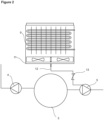
Figure 2 - is the top detailed schematic view of the evaporator, the condensation receptacle and the discharge hose. - The elements illustrated in the figures are numbered as follows.
- 1. Dishwasher
- 2. Tub
- 3. Washing water receptacle
- 4. Circulation pump
- 5. Discharge pump
- 6. Heat pump
- 7. Condenser
- 8. Compressor
- 9. Evaporator
- 10. Capillary tube
- 11. Condensation receptacle
- 12. Discharge hose
- 13. Valve
- The heat pump dishwasher (1) comprises a tub (2) wherein the dishes are placed; a washing water receptacle (3) which is disposed under the tub (2); a circulation pump (4) which is connected to the washing water receptacle (3) and which provides the transfer of the washing water to the tub (2); a discharge pump (5) which is connected to the washing water receptacle (3) and which provides the discharge of the dirt water; a heat pump (6) which is disposed under the tub (2) and which has at least one compressor (8), at least one evaporator (9), at least one condenser (7) and at least one capillary tube (10) which are connected to each other by means of a refrigerant fluid line through which the refrigerant fluid is circulated; a condensation receptacle (11) which is disposed under the evaporator (9) and wherein the water condensed in the evaporator (9) is collected; and a discharge hose (12) which is disposed between the condensation receptacle (11) and the discharge pump (5), one end of which is connected to the condensation receptacle (11) and the other end to the discharge pump (5), and which enables the water in the condensation receptacle (11) to be sucked and discharged when the discharge pump (5) is operated.
- In the embodiment of the present invention, the washing water is collected in the washing water receptacle (3) in the heat pump dishwasher (1). The washing water is taken from the washing water receptacle (3) by means of the circulation pump (4) and passed over the condenser (7) in the heat pump (6), and then, the washing water heated by means of the condenser (7) is transferred to the tub (2). At this stage, the heat pump (6) operates as follows:
The compressor (8) pressurizes the refrigerant fluid and sends the same to the condenser (7). Upon being pressurized by the compressor (8), the pressure and hence the temperature of the refrigerant fluid increase. Thus, the condenser (7) is heated. The water taken from the washing water receptacle (3) by means of the circulation pump (4) is passed over the condenser (7) and the washing water is heated. At the same time, the refrigerant fluid leaving the condenser (7) is directed to the capillary tube (10) and the pressure and hence the temperature of the refrigerant fluid are reduced. The refrigerant fluid leaving the capillary tube (10) is sent to the evaporator (9). Since the evaporator (9) is air sourced, the air passing over the evaporator (9) is moved away from the dishwasher (1) and sent to the environment, and thus heat transfer is performed from the environment to the evaporator (9). The refrigerant fluid leaving the evaporator (9) is sucked again by the compressor (8) and the refrigerant fluid cycle is completed. Since the temperature of the ambient air passing over the evaporator (9) is much higher than the surface temperature of the evaporator (9) and the surface temperature of the evaporator (9) is below the dew point temperature of the air, the air is dehumidified and condensed on the surface of the evaporator (9). The water droplets condensing on the surface of the evaporator (9) are collected in the condensation receptacle (11) disposed under the evaporator (9). When the discharge pump (5) is operated, negative pressure occurs in the discharge hose (12), one end of which is connected to the condensation receptacle (11) and the other end to the discharge pump (5), and the water in the condensation receptacle (11) is sucked towards the discharge pump (5). The water reaching the discharge pump (5) is discharged together with the water leaving the washing process (Figure 1 ). - In the embodiment of the invention, the discharge hose (12) is disposed between the condensation receptacle (11) under the evaporator (9) and the discharge pump (5), and is directly connected to the inlet of the discharge pump (5). Thus, when the discharge pump (5) is operated, negative pressure occurs in the discharge hose (12), and the water collected in the condensation receptacle (11) is sucked from the end of the discharge hose (12) connected to the condensation receptacle (11) to be delivered to the discharge pump (5) and discharged together with the discharged water.
- In an embodiment of the present invention, the dishwasher (1) comprises a valve (13) disposed on the discharge hose (12). In the preferred embodiment of the present invention, the valve (13) is a one-way valve. In this embodiment of the present invention, the valve (13) enables the water sucked from the condensation receptacle (11) to flow towards the discharge pump (5) and prevents the water from returning to the condensation receptacle (11) through the discharge hose (12). Thus, any backpressure in the discharge hose (12) is prevented.
- In another embodiment of the present invention, the dishwasher (1) comprises the discharge hose (12) which is connected to the discharge pump (5) at a 45° angle.
- In another embodiment of the present invention, the discharge hose (12) is connected to the discharge pump (5) at a 60° angle.
- In yet another embodiment of the present invention, the discharge hose (12) is connected to the discharge pump (5) at an angle of 90°.
- By means of the present invention, the water in the condensation receptacle (11) is enabled to be discharged without the need for the use of an additional pump, valve or sensor. Thus, the need for using components requiring control such as additional pump, valve and/or sensor is eliminated, saving costs. Moreover, since the additional noise source in the current embodiment is eliminated, the perception of quality is increased.
Claims (8)
- A heat pump dishwasher (1) comprising a tub (2) wherein the dishes are placed; a washing water receptacle (3) which is disposed under the tub (2); a circulation pump (4) which is connected to the washing water receptacle (3) and which provides the transfer of the washing water to the tub (2); a discharge pump (5) which is connected to the washing water receptacle (3) and which provides the discharge of the dirt water; a heat pump (6) which is disposed under the tub (2) and which has at least one compressor (8), at least one evaporator (9), at least one condenser (7) and at least one capillary tube (10) which are connected to each other by means of a refrigerant fluid line through which the refrigerant fluid is circulated; and a condensation receptacle (11) which is disposed under the evaporator (9) and wherein the water condensed in the evaporator (9) is collected, characterized by a discharge hose (12) which is disposed between the condensation receptacle (11) and the discharge pump (5), one end of which is connected to the condensation receptacle (11) and the other end to the discharge pump (5), and which enables the water in the condensation receptacle (11) to be sucked and discharged when the discharge pump (5) is operated.
- A dishwasher (1) as in Claim 1, characterized by the discharge hose (12) which is disposed between the condensation receptacle (11) under the evaporator (9) and the discharge pump (5) and which is directly connected to the inlet of the discharge pump (5).
- A dishwasher (1) as in Claim 1, characterized by a valve (13) disposed on the discharge hose (12).
- A dishwasher (1) as in Claim 3, characterized by the one-way valve (13).
- A dishwasher (1) as in Claim 3 or 4, characterized by the valve (13) which enables the water sucked from the condensation receptacle (11) to flow towards the discharge pump (5) and which prevents the water in the discharge hose (12) from returning to the condensation receptacle (11).
- A dishwasher (1) as in Claim 1, characterized by the discharge hose (12) which is connected to the discharge pump (5) at a 45° angle.
- A dishwasher (1) as in Claim 1, characterized by the discharge hose (12) which is connected to the discharge pump (5) at a 60° angle.
- A dishwasher (1) as in Claim 1, characterized by the discharge hose (12) which is connected to the discharge pump (5) at a 90° angle.
Applications Claiming Priority (1)
| Application Number | Priority Date | Filing Date | Title |
|---|---|---|---|
| TR202317739 | 2023-12-20 |
Publications (1)
| Publication Number | Publication Date |
|---|---|
| EP4574003A1 true EP4574003A1 (en) | 2025-06-25 |
Family
ID=92895514
Family Applications (1)
| Application Number | Title | Priority Date | Filing Date |
|---|---|---|---|
| EP24201955.2A Withdrawn EP4574003A1 (en) | 2023-12-20 | 2024-09-23 | A heat pump dishwasher and the control method thereof |
Country Status (1)
| Country | Link |
|---|---|
| EP (1) | EP4574003A1 (en) |
Citations (7)
| Publication number | Priority date | Publication date | Assignee | Title |
|---|---|---|---|---|
| KR20080091660A (en) * | 2007-04-09 | 2008-10-14 | 주식회사 대우일렉트로닉스 | Laundry dryer |
| DE102012105670A1 (en) | 2012-06-28 | 2014-01-02 | Miele & Cie. Kg | Domestic appliance e.g. tumble dryer has high-pressure pipe interpreted to produce rotary vibrations from compressor to heat exchanger, and pipe sections that are arranged in planes arranged perpendicular to each other |
| EP2682036A2 (en) * | 2012-07-03 | 2014-01-08 | Miele & Cie. KG | Dishwasher and method for heating of the wash liquor in a dishwasher |
| WO2016004990A1 (en) | 2014-07-09 | 2016-01-14 | Electrolux Appliances Aktiebolag | Method of operating a dishwasher and a dishwasher |
| EP3473155A1 (en) * | 2017-10-18 | 2019-04-24 | Miele & Cie. KG | Dishwasher |
| EP3173513B1 (en) * | 2013-06-11 | 2020-05-13 | Electrolux Appliances Aktiebolag | Washing machine |
| EP3718461A1 (en) | 2019-04-05 | 2020-10-07 | Miele & Cie. KG | Dishwasher, in particular a domestic dishwashing machine |
-
2024
- 2024-09-23 EP EP24201955.2A patent/EP4574003A1/en not_active Withdrawn
Patent Citations (7)
| Publication number | Priority date | Publication date | Assignee | Title |
|---|---|---|---|---|
| KR20080091660A (en) * | 2007-04-09 | 2008-10-14 | 주식회사 대우일렉트로닉스 | Laundry dryer |
| DE102012105670A1 (en) | 2012-06-28 | 2014-01-02 | Miele & Cie. Kg | Domestic appliance e.g. tumble dryer has high-pressure pipe interpreted to produce rotary vibrations from compressor to heat exchanger, and pipe sections that are arranged in planes arranged perpendicular to each other |
| EP2682036A2 (en) * | 2012-07-03 | 2014-01-08 | Miele & Cie. KG | Dishwasher and method for heating of the wash liquor in a dishwasher |
| EP3173513B1 (en) * | 2013-06-11 | 2020-05-13 | Electrolux Appliances Aktiebolag | Washing machine |
| WO2016004990A1 (en) | 2014-07-09 | 2016-01-14 | Electrolux Appliances Aktiebolag | Method of operating a dishwasher and a dishwasher |
| EP3473155A1 (en) * | 2017-10-18 | 2019-04-24 | Miele & Cie. KG | Dishwasher |
| EP3718461A1 (en) | 2019-04-05 | 2020-10-07 | Miele & Cie. KG | Dishwasher, in particular a domestic dishwashing machine |
Similar Documents
| Publication | Publication Date | Title |
|---|---|---|
| CN106455901B (en) | Method of operating a dishwasher and dishwasher | |
| EP3241944A1 (en) | Household appliance having a process air circuit | |
| EP3291720B1 (en) | A dishwasher comprising a heat pump | |
| EP3731718B1 (en) | A heat pump dishwasher | |
| CN110595119A (en) | Compressor liquid return treatment device and air conditioner | |
| EP3241943B1 (en) | Household appliance comprising a water/process air heat exchanger | |
| EP2192370A1 (en) | Device for vapour condensation and for energy recovery | |
| EP3226742B1 (en) | A heat pump dishwasher | |
| EP3731720B1 (en) | A heat pump dishwasher | |
| EP3855996B1 (en) | A heat pump dishwasher comprising an evaporator tray | |
| CN219222691U (en) | Dehumidifier | |
| WO2018228808A1 (en) | A dishwasher comprising a heat pump | |
| TR2023017739A2 (en) | A HEAT PUMP DISHWASHER AND ITS CONTROL METHOD | |
| EP3855997B1 (en) | A heat pump dishwasher with reduced energy consumption | |
| EP3731717B1 (en) | A heat pump dishwasher with decreased water consumption | |
| JPH11287470A (en) | Air conditioner drain panel | |
| CN106480675A (en) | There is the clothes treatment device of clothes drying function | |
| EP4461192B1 (en) | A dishwasher comprising a heat pump | |
| EP3982811B1 (en) | A dishwasher comprising a heat pump | |
| CN209512256U (en) | Air conditioning condensate treatment device, air conditioner | |
| WO2019034373A1 (en) | A dishwasher comprising a heat pump | |
| WO2020083592A1 (en) | A heat pump dishwasher with improved evaporator performance | |
| EP3860421B1 (en) | A heat pump dishwasher comprising a defrost line | |
| CN121445284A (en) | Control method of washing electric appliance and washing electric appliance | |
| WO2020057829A1 (en) | A dishwasher comprising a heat pump |
Legal Events
| Date | Code | Title | Description |
|---|---|---|---|
| PUAI | Public reference made under article 153(3) epc to a published international application that has entered the european phase |
Free format text: ORIGINAL CODE: 0009012 |
|
| STAA | Information on the status of an ep patent application or granted ep patent |
Free format text: STATUS: REQUEST FOR EXAMINATION WAS MADE |
|
| 17P | Request for examination filed |
Effective date: 20240923 |
|
| AK | Designated contracting states |
Kind code of ref document: A1 Designated state(s): AL AT BE BG CH CY CZ DE DK EE ES FI FR GB GR HR HU IE IS IT LI LT LU LV MC ME MK MT NL NO PL PT RO RS SE SI SK SM TR |
|
| STAA | Information on the status of an ep patent application or granted ep patent |
Free format text: STATUS: THE APPLICATION IS DEEMED TO BE WITHDRAWN |
|
| 18D | Application deemed to be withdrawn |
Effective date: 20260103 |