EP3860421B1 - A heat pump dishwasher comprising a defrost line - Google Patents
A heat pump dishwasher comprising a defrost line Download PDFInfo
- Publication number
- EP3860421B1 EP3860421B1 EP19761835.8A EP19761835A EP3860421B1 EP 3860421 B1 EP3860421 B1 EP 3860421B1 EP 19761835 A EP19761835 A EP 19761835A EP 3860421 B1 EP3860421 B1 EP 3860421B1
- Authority
- EP
- European Patent Office
- Prior art keywords
- water
- evaporator
- dishwasher
- container
- pump
- Prior art date
- Legal status (The legal status is an assumption and is not a legal conclusion. Google has not performed a legal analysis and makes no representation as to the accuracy of the status listed.)
- Active
Links
- XLYOFNOQVPJJNP-UHFFFAOYSA-N water Substances O XLYOFNOQVPJJNP-UHFFFAOYSA-N 0.000 claims description 75
- 238000005406 washing Methods 0.000 claims description 20
- 238000010438 heat treatment Methods 0.000 claims description 15
- 239000003507 refrigerant Substances 0.000 claims description 10
- 239000003570 air Substances 0.000 claims description 6
- 238000009833 condensation Methods 0.000 claims description 6
- 230000005494 condensation Effects 0.000 claims description 6
- 239000012080 ambient air Substances 0.000 claims description 4
- 238000007664 blowing Methods 0.000 claims description 2
- 239000002699 waste material Substances 0.000 claims description 2
- 230000007423 decrease Effects 0.000 description 4
- 230000003247 decreasing effect Effects 0.000 description 4
- 238000001035 drying Methods 0.000 description 4
- 238000005265 energy consumption Methods 0.000 description 3
- 238000007710 freezing Methods 0.000 description 3
- 230000008014 freezing Effects 0.000 description 3
- 239000012530 fluid Substances 0.000 description 2
- 230000007257 malfunction Effects 0.000 description 2
- 239000002918 waste heat Substances 0.000 description 2
- 239000002351 wastewater Substances 0.000 description 2
- 238000010521 absorption reaction Methods 0.000 description 1
- 239000004020 conductor Substances 0.000 description 1
- 238000001816 cooling Methods 0.000 description 1
- 238000000034 method Methods 0.000 description 1
- 238000004904 shortening Methods 0.000 description 1
Images


Classifications
-
- A—HUMAN NECESSITIES
- A47—FURNITURE; DOMESTIC ARTICLES OR APPLIANCES; COFFEE MILLS; SPICE MILLS; SUCTION CLEANERS IN GENERAL
- A47L—DOMESTIC WASHING OR CLEANING; SUCTION CLEANERS IN GENERAL
- A47L15/00—Washing or rinsing machines for crockery or tableware
- A47L15/42—Details
- A47L15/4291—Recovery arrangements, e.g. for the recovery of energy or water
-
- A—HUMAN NECESSITIES
- A47—FURNITURE; DOMESTIC ARTICLES OR APPLIANCES; COFFEE MILLS; SPICE MILLS; SUCTION CLEANERS IN GENERAL
- A47L—DOMESTIC WASHING OR CLEANING; SUCTION CLEANERS IN GENERAL
- A47L15/00—Washing or rinsing machines for crockery or tableware
- A47L15/42—Details
- A47L15/4285—Water-heater arrangements
-
- Y—GENERAL TAGGING OF NEW TECHNOLOGICAL DEVELOPMENTS; GENERAL TAGGING OF CROSS-SECTIONAL TECHNOLOGIES SPANNING OVER SEVERAL SECTIONS OF THE IPC; TECHNICAL SUBJECTS COVERED BY FORMER USPC CROSS-REFERENCE ART COLLECTIONS [XRACs] AND DIGESTS
- Y02—TECHNOLOGIES OR APPLICATIONS FOR MITIGATION OR ADAPTATION AGAINST CLIMATE CHANGE
- Y02B—CLIMATE CHANGE MITIGATION TECHNOLOGIES RELATED TO BUILDINGS, e.g. HOUSING, HOUSE APPLIANCES OR RELATED END-USER APPLICATIONS
- Y02B30/00—Energy efficient heating, ventilation or air conditioning [HVAC]
- Y02B30/52—Heat recovery pumps, i.e. heat pump based systems or units able to transfer the thermal energy from one area of the premises or part of the facilities to a different one, improving the overall efficiency
Definitions
- the present invention relates to a heat pump dishwasher.
- the heat pump system in the heat pump dishwashers is composed of a compressor which provides the circulation of a refrigerant (refrigerant fluid), a condenser, an evaporator, and an expansion element. Said components are connected to each other by means of a pipe line, and by means of the fluid passing through the pipe line, the cycle is performed. The aim of said cycle is to heat the washing water.
- the evaporator draws heat from the environment to the heat pump system, and the condenser transfers the heat of the heat pump system to the washing water.
- the evaporator which is of air source type, draws heat from the environment and transfers, together with the compressor, heat to the condenser.
- the condenser transfers the heat to the washing water in the dishwasher.
- the heat pump is operated in ambient conditions colder than normal, for example between 0°C and 10°C, the temperature of the evaporator falls below 0°C to draw heat from the environment.
- the water is frozen in an evaporator which uses water as an auxiliary heat source, water circulation in the pipe delivering water to the evaporator stops.
- the evaporator tries to draw heat only from the air source, that is the ambient air, and cannot draw heat from water. Therefore, the heat pump efficiency decreases while energy consumption increases.
- the volume of the water frozen in the pipes delivering water to the evaporator increases, the pipes may explode due to expansion.
- the Patent No. EP2594185 (B1 ) relates to a heat pump dishwasher.
- the evaporator operates in the waste water tank, and thus the heat pump draws heat from the water in the waste water tank.
- the Patent No. EP2658430 (B1 ) relates to a heat pump dishwasher.
- the evaporator and the condenser are disposed in separate water tanks.
- EP2978360 relates to the washing apparatus of the invention includes a heat pump.
- EP2215954 relates to a dishwasher and a method to improve the energy efficiency of a dishwasher.
- EP3372140 relates to a dishwasher comprising a water tank which is arranged adjacent to the washing tank and which is fluidically connected to the water tank.
- the aim of the present invention is the realization of a heat pump dishwasher wherein the problem of freezing in the evaporator is eliminated, thus decreasing energy consumption.
- Such a dishwasher is of heat pump type, and comprises a compressor, a condenser, and an evaporator.
- heating pipes are provided between the refrigerant pipes in the evaporator, and the evaporator draws heat from the hot water flowing through the heating pipes.
- a container is disposed on the compressor and/or an electronic card controlling the compressor, and the water in the container is heated. By means of a defrost line, the hot water in the container is circulated in the heating pipes in the evaporator.
- a heat pump dishwasher is illustrated in the attached figures, where:
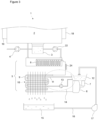
- the dishwasher (1) comprises a tub (2); a circulation pump (22) which provides the delivery of the washing water into the washing environment in the tub (2); a sump (3) which is disposed under the tub (2) and wherein the washing water is collected; a discharge pump (4) which enables the water collected in the sump (3) at the end of the washing process to be discharged to the outside; at least one rack (23) wherein the dishes to be washed are loaded; and a heat pump (5) which heats the washing water.
- the heat pump (5) comprises a compressor (6) which performs the refrigerant cycle; an electronic card (7) which controls the compressor (6); a condenser (8) which is used for heating the washing water; an evaporator (10) which draws heat from the outer environment and which is composed of refrigerant tubes (9) and of fins; and an expansion element (24), for example a capillary tube or an expansion valve, which is disposed between the condenser (8) and the evaporator (10) and which decreases the pressure of the refrigerant.
- an expansion element for example a capillary tube or an expansion valve, which is disposed between the condenser (8) and the evaporator (10) and which decreases the pressure of the refrigerant.
- the dishwasher (1) of the present invention comprises
- the container (12), which is produced from a heat-conducting material is disposed on the compressor (6) and/or the electronic card (7).
- the water in the container (12) is delivered to the heating pipes (11) in the evaporator (10) by means of the defrost pump (13) and the defrost line (14) so as to be circulated. Since the temperature of the water delivered to the evaporator (10) is increased, the risk of freezing is decreased. Since the heat drawn by the evaporator (10) from the outside increases, the performance thereof is improved while decreasing the operational time of the heat pump (5).
- the hot water in the heating pipe (11) cools down while circulating in the evaporator (10) and returns to the container (12) in cold state.
- the compressor (6) and/or the electronic card (7) which continuously heats the water in the container (12) is enabled to be cooled down, increasing the working life of the compressor (6) and preventing malfunctions by cooling down the components in the electronic card (7) which excessively heat up.
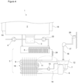
- waste washing water which is collected in the sump (3), is delivered to the container (12) by means of the discharge pump (4) and a water supply line (16) so as to be heated and circulated in the defrost line (14).
- the sump (3) is used as a water source for the container (12).
- the discharge pump (4) delivers the water collected in the sump (3) at the end of the washing process to the container (12).
- the discharged water which is already hot, is heated more with the waste heat of the compressor (6) and/or the electronic card (7) to be delivered to the heating pipes (11) in the evaporator (10) ( Figure 2 ).
- the dishwasher (1) comprises a condensation receptacle (15) which is disposed under the evaporator (10) and wherein the water condensing on the evaporator (10) surface is collected, and the water collected in the condensation receptacle (15) is delivered into the container (12) by means of the water supply line (16) and a water supply pump (17) so as to be heated.
- the condensation receptacle (15) is used as a water source for the container (12) ( Figure 3 ).
- the dishwasher (1) comprises an auxiliary water tank (18) which enables the water to be collected before the washing process and brought to the ambient temperature and thus shortening the water heating time during the washing process and providing savings in energy, and the water in the auxiliary water tank (18) is delivered into the container (12) by means of the water supply line (16) and the water supply pump (17) so as to be heated.
- the auxiliary water tank (18) is used as a water source for the container (12) ( Figure 1 ).
- the dishwasher (1) comprises a drying duct (19) which takes the humid air in the tub (2) out of the tub (2) after the washing process and thus enables the washed items to be dried, and the water in the drying duct (19) is delivered into the container (12) by means of the water supply line (16) and the water supply pump (17).
- the drying duct (19) is used as a water source for the container (12).
- the water taken from the water mains (20) is delivered into the container (12) by means of the water supply line (16) and the water supply pump (17) so as to be heated ( Figure 4 ).
- the evaporator (10) is an evaporator (10) which is heated by air in addition to the water circulated therein by means of the heating pipes (11), and the dishwasher (1) comprises at least one fan (21) which provides the heat transfer by blowing the ambient air onto the evaporator (10) ( Figure 1 ).
- the defrost line (14) eliminates the problem of freezing in the heating pipes (11) which circulate hot water in the evaporator (10).
- the water the temperature of which increases in the container (12) with the waste heat of the compressor (6), increases the heat absorption capacity of the evaporator (10), thus decreasing energy consumption.
- the compressor (6) and the electronic card (7) are cooled down, thus preventing malfunctions.
Description
- The present invention relates to a heat pump dishwasher.
- The heat pump system in the heat pump dishwashers is composed of a compressor which provides the circulation of a refrigerant (refrigerant fluid), a condenser, an evaporator, and an expansion element. Said components are connected to each other by means of a pipe line, and by means of the fluid passing through the pipe line, the cycle is performed. The aim of said cycle is to heat the washing water. To this end, the evaporator draws heat from the environment to the heat pump system, and the condenser transfers the heat of the heat pump system to the washing water. In some embodiments, the evaporator, which is of air source type, draws heat from the environment and transfers, together with the compressor, heat to the condenser. The condenser transfers the heat to the washing water in the dishwasher. In such a heat pump dishwasher, the temperature of the outer environment is not sufficient for the evaporator, and it is required to transfer more stable heat to the evaporator. An evaporator which can draw heat both from the ambient air and from water to solve this problem is disclosed in the International Patent Application No.
PCT/EP2018/056400 WO2018/188883A1 and potentially prior art under Article 54(3) EPC. Basically, when the temperature in an environment wherein an evaporator, which operates with air but uses water as an auxiliary heat source, decreases, the heat drawn by the evaporator also decreases. If the heat pump is operated in ambient conditions colder than normal, for example between 0°C and 10°C, the temperature of the evaporator falls below 0°C to draw heat from the environment. In this case, since the water is frozen in an evaporator which uses water as an auxiliary heat source, water circulation in the pipe delivering water to the evaporator stops. In this case, the evaporator tries to draw heat only from the air source, that is the ambient air, and cannot draw heat from water. Therefore, the heat pump efficiency decreases while energy consumption increases. Moreover, since the volume of the water frozen in the pipes delivering water to the evaporator increases, the pipes may explode due to expansion. - The Patent No.
EP2594185 (B1 ) relates to a heat pump dishwasher. The evaporator operates in the waste water tank, and thus the heat pump draws heat from the water in the waste water tank. The Patent No.EP2658430 (B1 ) relates to a heat pump dishwasher. The evaporator and the condenser are disposed in separate water tanks. - In the state of the art the European patent application no.
EP2978360 relates to the washing apparatus of the invention includes a heat pump. - In the state of the art the European patent application no.
EP2215954 relates to a dishwasher and a method to improve the energy efficiency of a dishwasher. - In the state of the art the European patent application no.
EP3372140 relates to a dishwasher comprising a water tank which is arranged adjacent to the washing tank and which is fluidically connected to the water tank. - The aim of the present invention is the realization of a heat pump dishwasher wherein the problem of freezing in the evaporator is eliminated, thus decreasing energy consumption.
- The dishwasher realized in order to attain the aim of the present invention is defined in
independent claim 1. Such a dishwasher is of heat pump type, and comprises a compressor, a condenser, and an evaporator. For instance, heating pipes are provided between the refrigerant pipes in the evaporator, and the evaporator draws heat from the hot water flowing through the heating pipes. A container is disposed on the compressor and/or an electronic card controlling the compressor, and the water in the container is heated. By means of a defrost line, the hot water in the container is circulated in the heating pipes in the evaporator. - A heat pump dishwasher is illustrated in the attached figures, where:
-
Figure 1 - is the schematic view of a heat pump dishwasher. -
Figure 2 - is the detailed schematic view of the dishwasher in an embodiment of the present invention. -
Figure 3 - is the detailed schematic view of the dishwasher in another embodiment of the present invention. -
Figure 4 - is the detailed schematic view of another heat pump dishwasher - The elements illustrated in the figures are numbered as follows:
- 1. Dishwasher
- 2. Tub
- 3. Sump
- 4. Discharge pump
- 5. Heat pump
- 6. Compressor
- 7. Electronic card
- 8. Condenser
- 9. Refrigerant tube
- 10. Evaporator
- 11. Heating pipe
- 12. Container
- 13. Defrost pump
- 14. Defrost line
- 15. Condensation receptacle
- 16. Water supply line
- 17. Water supply pump
- 18. Auxiliary water tank
- 19. Drying duct
- 20. Mains tap
- 21. Fan
- 22. Circulation pump
- 23. Rack
- 24. Expansion element
- The dishwasher (1) comprises a tub (2); a circulation pump (22) which provides the delivery of the washing water into the washing environment in the tub (2); a sump (3) which is disposed under the tub (2) and wherein the washing water is collected; a discharge pump (4) which enables the water collected in the sump (3) at the end of the washing process to be discharged to the outside; at least one rack (23) wherein the dishes to be washed are loaded; and a heat pump (5) which heats the washing water.
- The heat pump (5) comprises a compressor (6) which performs the refrigerant cycle; an electronic card (7) which controls the compressor (6); a condenser (8) which is used for heating the washing water; an evaporator (10) which draws heat from the outer environment and which is composed of refrigerant tubes (9) and of fins; and an expansion element (24), for example a capillary tube or an expansion valve, which is disposed between the condenser (8) and the evaporator (10) and which decreases the pressure of the refrigerant.
- The dishwasher (1) of the present invention comprises
- at least one heating pipe (11) which is disposed between the refrigerant tubes (9) of the evaporator (10) and through which hot water is passed,
- a container (12) which is disposed on the compressor (6) and/or the electronica card (7), and
- a defrost line (14) which provides the circulation of the water, which is heated in the container (12) by the compressor (6) and/or the electronic card (7) during the operation of the heat pump (5), between the container (12) and the heating pipe (11) by means of a defrost pump (13) (
Figure 1 ). - The container (12), which is produced from a heat-conducting material is disposed on the compressor (6) and/or the electronic card (7). The water in the container (12) is delivered to the heating pipes (11) in the evaporator (10) by means of the defrost pump (13) and the defrost line (14) so as to be circulated. Since the temperature of the water delivered to the evaporator (10) is increased, the risk of freezing is decreased. Since the heat drawn by the evaporator (10) from the outside increases, the performance thereof is improved while decreasing the operational time of the heat pump (5). The hot water in the heating pipe (11) cools down while circulating in the evaporator (10) and returns to the container (12) in cold state. Thus, the compressor (6) and/or the electronic card (7) which continuously heats the water in the container (12) is enabled to be cooled down, increasing the working life of the compressor (6) and preventing malfunctions by cooling down the components in the electronic card (7) which excessively heat up.
- In an embodiment of the present invention, waste washing water, which is collected in the sump (3), is delivered to the container (12) by means of the discharge pump (4) and a water supply line (16) so as to be heated and circulated in the defrost line (14). The sump (3) is used as a water source for the container (12). The discharge pump (4) delivers the water collected in the sump (3) at the end of the washing process to the container (12). Thus, the discharged water, which is already hot, is heated more with the waste heat of the compressor (6) and/or the electronic card (7) to be delivered to the heating pipes (11) in the evaporator (10) (
Figure 2 ). In another embodiment of the present invention, the dishwasher (1) comprises a condensation receptacle (15) which is disposed under the evaporator (10) and wherein the water condensing on the evaporator (10) surface is collected, and the water collected in the condensation receptacle (15) is delivered into the container (12) by means of the water supply line (16) and a water supply pump (17) so as to be heated. The condensation receptacle (15) is used as a water source for the container (12) (Figure 3 ). - In an example which does not form part of the present invention, the dishwasher (1) comprises an auxiliary water tank (18) which enables the water to be collected before the washing process and brought to the ambient temperature and thus shortening the water heating time during the washing process and providing savings in energy, and the water in the auxiliary water tank (18) is delivered into the container (12) by means of the water supply line (16) and the water supply pump (17) so as to be heated. The auxiliary water tank (18) is used as a water source for the container (12) (
Figure 1 ). - In an example which does not form part of the present invention, the dishwasher (1) comprises a drying duct (19) which takes the humid air in the tub (2) out of the tub (2) after the washing process and thus enables the washed items to be dried, and the water in the drying duct (19) is delivered into the container (12) by means of the water supply line (16) and the water supply pump (17). The drying duct (19) is used as a water source for the container (12).
- In an example which does not form part of the present invention, the water taken from the water mains (20) is delivered into the container (12) by means of the water supply line (16) and the water supply pump (17) so as to be heated (
Figure 4 ). - In another embodiment of the present invention, the evaporator (10) is an evaporator (10) which is heated by air in addition to the water circulated therein by means of the heating pipes (11), and the dishwasher (1) comprises at least one fan (21) which provides the heat transfer by blowing the ambient air onto the evaporator (10) (
Figure 1 ). - In the dishwasher (1) of the present invention, the defrost line (14) eliminates the problem of freezing in the heating pipes (11) which circulate hot water in the evaporator (10). The water, the temperature of which increases in the container (12) with the waste heat of the compressor (6), increases the heat absorption capacity of the evaporator (10), thus decreasing energy consumption. The compressor (6) and the electronic card (7) are cooled down, thus preventing malfunctions.
Claims (2)
- - A dishwasher (1) comprising a tub (2); a sump (3) which is disposed under the tub (2) and wherein washing water is collected; a discharge pump (4) which enables water collected in the sump (3) at the end of a washing process to be discharged to the outside; a heat pump (5) which heats the washing water; and a compressor (6), an electronic card (7), a condenser (8) and an evaporator (10) composed of refrigerant tubes (9) and fins, which all together constitute the heat pump (5), and a container (12) which is disposed on the compressor (6) and/or an electronic card (7), characterized in that the dishwasher comprises at least one heating pipe (11) which is disposed between the refrigerant tubes (9) of the evaporator (10) and through which hot water is passed, a defrost line (14) which provides circulation of the water, which is heated in the container (12) by the compressor (6) and/or the electronic card (7), between the container (12) and the heating pipe (11) by means of a defrost pump (13) wherein the dishwasher is further characterized by the discharge pump (4) and a water supply line (16) which enable waste washing water, which is collected in the sump (3), to be delivered to the container (12) so as to be heated and circulated in the defrost line (14), or wherein the dishwasher is further characterized by a condensation receptacle (15) wherein water condensing on the evaporator (10) surface is collected, and by the water supply line (16) and a water supply pump (17) which enable the water in the condensation receptacle (15) to be delivered into the container (12) so as to be heated.
- - A dishwasher (1) as in Claim 1, characterized by the evaporator (10) which is heated by air in addition to water, and by at least one fan (21) which provides the heat transfer by blowing the ambient air onto the evaporator (10).
Applications Claiming Priority (2)
| Application Number | Priority Date | Filing Date | Title |
|---|---|---|---|
| TR201814325 | 2018-10-02 | ||
| PCT/EP2019/073036 WO2020069800A1 (en) | 2018-10-02 | 2019-08-29 | A heat pump dishwasher comprising a defrost line |
Publications (2)
| Publication Number | Publication Date |
|---|---|
| EP3860421A1 EP3860421A1 (en) | 2021-08-11 |
| EP3860421B1 true EP3860421B1 (en) | 2023-08-02 |
Family
ID=67809482
Family Applications (1)
| Application Number | Title | Priority Date | Filing Date |
|---|---|---|---|
| EP19761835.8A Active EP3860421B1 (en) | 2018-10-02 | 2019-08-29 | A heat pump dishwasher comprising a defrost line |
Country Status (3)
| Country | Link |
|---|---|
| EP (1) | EP3860421B1 (en) |
| PL (1) | PL3860421T3 (en) |
| WO (1) | WO2020069800A1 (en) |
Family Cites Families (10)
| Publication number | Priority date | Publication date | Assignee | Title |
|---|---|---|---|---|
| JP2004239506A (en) * | 2003-02-05 | 2004-08-26 | Denso Corp | Heat pump unit |
| PL2064982T3 (en) * | 2009-02-09 | 2012-11-30 | V Zug Ag | Dishwasher with heat pump |
| EP2096203B1 (en) * | 2009-05-28 | 2012-01-25 | V-Zug AG | Household washing machine with heat pump |
| CH699692B1 (en) * | 2010-02-15 | 2013-09-30 | V Zug Ag | Dishwasher with several water tanks. |
| DK2224049T3 (en) * | 2010-06-11 | 2012-10-29 | V Zug Ag | Wastewater tank wastewater and heat pump and method for controlling this wastewater |
| EP2574266B1 (en) | 2010-12-29 | 2015-10-21 | Electrolux Home Products Corporation N.V. | Heat pump ice pipe |
| PL2728052T3 (en) * | 2012-10-30 | 2017-08-31 | Electrolux Home Products Corporation N.V. | Washing machine |
| SI2594185T1 (en) | 2013-02-07 | 2016-07-29 | V-Zug Ag | Cleaning device with tub, waste water tank and connecting line |
| WO2014154278A1 (en) * | 2013-03-28 | 2014-10-02 | Electrolux Appliances Aktiebolag | Heat pump washing apparatus |
| EP3372140B1 (en) * | 2017-03-08 | 2022-06-01 | Miele & Cie. KG | Dishwasher, in particular domestic dishwasher |
-
2019
- 2019-08-29 EP EP19761835.8A patent/EP3860421B1/en active Active
- 2019-08-29 PL PL19761835.8T patent/PL3860421T3/en unknown
- 2019-08-29 WO PCT/EP2019/073036 patent/WO2020069800A1/en unknown
Also Published As
| Publication number | Publication date |
|---|---|
| WO2020069800A1 (en) | 2020-04-09 |
| EP3860421A1 (en) | 2021-08-11 |
| PL3860421T3 (en) | 2024-01-29 |
Similar Documents
| Publication | Publication Date | Title |
|---|---|---|
| US9574804B2 (en) | Household appliance | |
| EP3379992B1 (en) | Household appliance with a heat pump and method for operating a household appliance | |
| EP3226742B1 (en) | A heat pump dishwasher | |
| EP3860421B1 (en) | A heat pump dishwasher comprising a defrost line | |
| CN208920434U (en) | Air conditioner type washs electric appliance | |
| EP3801178B1 (en) | Heat pump dishwasher with enhanced evaporator capacity | |
| EP3801179B1 (en) | Heat pump dishwasher with enhanced evaporator efficiency | |
| CN109000317A (en) | Air conditioner type washs electric appliance | |
| EP3855997B1 (en) | A heat pump dishwasher with reduced energy consumption | |
| EP3609382B1 (en) | A dishwasher | |
| WO2020069802A1 (en) | A heat pump dishwasher comprising a defrost system | |
| CN209315776U (en) | Wash electric appliance | |
| WO2019129404A1 (en) | A heat pump dishwasher with decreased water consumption | |
| EP3226741B1 (en) | A heat pump dishwasher | |
| EP3731720B1 (en) | A heat pump dishwasher | |
| WO2020057829A1 (en) | A dishwasher comprising a heat pump | |
| WO2019034373A1 (en) | A dishwasher comprising a heat pump | |
| WO2020057843A1 (en) | A dishwasher comprising a heat pump | |
| WO2020083591A1 (en) | A heat pump dishwasher comprising a defrost receptacle | |
| TR2021005482T (en) | HEAT PUMP DISHWASHER WITH DEFROST SYSTEM | |
| EP3638090A1 (en) | A dishwasher comprising a heat pump |
Legal Events
| Date | Code | Title | Description |
|---|---|---|---|
| STAA | Information on the status of an ep patent application or granted ep patent |
Free format text: STATUS: UNKNOWN |
|
| STAA | Information on the status of an ep patent application or granted ep patent |
Free format text: STATUS: THE INTERNATIONAL PUBLICATION HAS BEEN MADE |
|
| PUAI | Public reference made under article 153(3) epc to a published international application that has entered the european phase |
Free format text: ORIGINAL CODE: 0009012 |
|
| STAA | Information on the status of an ep patent application or granted ep patent |
Free format text: STATUS: REQUEST FOR EXAMINATION WAS MADE |
|
| 17P | Request for examination filed |
Effective date: 20210330 |
|
| AK | Designated contracting states |
Kind code of ref document: A1 Designated state(s): AL AT BE BG CH CY CZ DE DK EE ES FI FR GB GR HR HU IE IS IT LI LT LU LV MC MK MT NL NO PL PT RO RS SE SI SK SM TR |
|
| DAV | Request for validation of the european patent (deleted) | ||
| DAX | Request for extension of the european patent (deleted) | ||
| GRAP | Despatch of communication of intention to grant a patent |
Free format text: ORIGINAL CODE: EPIDOSNIGR1 |
|
| STAA | Information on the status of an ep patent application or granted ep patent |
Free format text: STATUS: GRANT OF PATENT IS INTENDED |
|
| INTG | Intention to grant announced |
Effective date: 20230411 |
|
| GRAS | Grant fee paid |
Free format text: ORIGINAL CODE: EPIDOSNIGR3 |
|
| GRAA | (expected) grant |
Free format text: ORIGINAL CODE: 0009210 |
|
| STAA | Information on the status of an ep patent application or granted ep patent |
Free format text: STATUS: THE PATENT HAS BEEN GRANTED |
|
| AK | Designated contracting states |
Kind code of ref document: B1 Designated state(s): AL AT BE BG CH CY CZ DE DK EE ES FI FR GB GR HR HU IE IS IT LI LT LU LV MC MK MT NL NO PL PT RO RS SE SI SK SM TR |
|
| REG | Reference to a national code |
Ref country code: GB Ref legal event code: FG4D |
|
| REG | Reference to a national code |
Ref country code: CH Ref legal event code: EP |
|
| REG | Reference to a national code |
Ref country code: DE Ref legal event code: R096 Ref document number: 602019034098 Country of ref document: DE |
|
| REG | Reference to a national code |
Ref country code: IE Ref legal event code: FG4D |
|
| REG | Reference to a national code |
Ref country code: LT Ref legal event code: MG9D |
|
| REG | Reference to a national code |
Ref country code: NL Ref legal event code: MP Effective date: 20230802 |
|
| REG | Reference to a national code |
Ref country code: AT Ref legal event code: MK05 Ref document number: 1593685 Country of ref document: AT Kind code of ref document: T Effective date: 20230802 |
|
| PG25 | Lapsed in a contracting state [announced via postgrant information from national office to epo] |
Ref country code: GR Free format text: LAPSE BECAUSE OF FAILURE TO SUBMIT A TRANSLATION OF THE DESCRIPTION OR TO PAY THE FEE WITHIN THE PRESCRIBED TIME-LIMIT Effective date: 20231103 |
|
| PG25 | Lapsed in a contracting state [announced via postgrant information from national office to epo] |
Ref country code: IS Free format text: LAPSE BECAUSE OF FAILURE TO SUBMIT A TRANSLATION OF THE DESCRIPTION OR TO PAY THE FEE WITHIN THE PRESCRIBED TIME-LIMIT Effective date: 20231202 |
|
| PG25 | Lapsed in a contracting state [announced via postgrant information from national office to epo] |
Ref country code: SE Free format text: LAPSE BECAUSE OF FAILURE TO SUBMIT A TRANSLATION OF THE DESCRIPTION OR TO PAY THE FEE WITHIN THE PRESCRIBED TIME-LIMIT Effective date: 20230802 Ref country code: RS Free format text: LAPSE BECAUSE OF FAILURE TO SUBMIT A TRANSLATION OF THE DESCRIPTION OR TO PAY THE FEE WITHIN THE PRESCRIBED TIME-LIMIT Effective date: 20230802 Ref country code: PT Free format text: LAPSE BECAUSE OF FAILURE TO SUBMIT A TRANSLATION OF THE DESCRIPTION OR TO PAY THE FEE WITHIN THE PRESCRIBED TIME-LIMIT Effective date: 20231204 Ref country code: NO Free format text: LAPSE BECAUSE OF FAILURE TO SUBMIT A TRANSLATION OF THE DESCRIPTION OR TO PAY THE FEE WITHIN THE PRESCRIBED TIME-LIMIT Effective date: 20231102 Ref country code: NL Free format text: LAPSE BECAUSE OF FAILURE TO SUBMIT A TRANSLATION OF THE DESCRIPTION OR TO PAY THE FEE WITHIN THE PRESCRIBED TIME-LIMIT Effective date: 20230802 Ref country code: LV Free format text: LAPSE BECAUSE OF FAILURE TO SUBMIT A TRANSLATION OF THE DESCRIPTION OR TO PAY THE FEE WITHIN THE PRESCRIBED TIME-LIMIT Effective date: 20230802 Ref country code: LT Free format text: LAPSE BECAUSE OF FAILURE TO SUBMIT A TRANSLATION OF THE DESCRIPTION OR TO PAY THE FEE WITHIN THE PRESCRIBED TIME-LIMIT Effective date: 20230802 Ref country code: IS Free format text: LAPSE BECAUSE OF FAILURE TO SUBMIT A TRANSLATION OF THE DESCRIPTION OR TO PAY THE FEE WITHIN THE PRESCRIBED TIME-LIMIT Effective date: 20231202 Ref country code: HR Free format text: LAPSE BECAUSE OF FAILURE TO SUBMIT A TRANSLATION OF THE DESCRIPTION OR TO PAY THE FEE WITHIN THE PRESCRIBED TIME-LIMIT Effective date: 20230802 Ref country code: GR Free format text: LAPSE BECAUSE OF FAILURE TO SUBMIT A TRANSLATION OF THE DESCRIPTION OR TO PAY THE FEE WITHIN THE PRESCRIBED TIME-LIMIT Effective date: 20231103 Ref country code: FI Free format text: LAPSE BECAUSE OF FAILURE TO SUBMIT A TRANSLATION OF THE DESCRIPTION OR TO PAY THE FEE WITHIN THE PRESCRIBED TIME-LIMIT Effective date: 20230802 Ref country code: AT Free format text: LAPSE BECAUSE OF FAILURE TO SUBMIT A TRANSLATION OF THE DESCRIPTION OR TO PAY THE FEE WITHIN THE PRESCRIBED TIME-LIMIT Effective date: 20230802 |
|
| PGFP | Annual fee paid to national office [announced via postgrant information from national office to epo] |
Ref country code: TR Payment date: 20231030 Year of fee payment: 5 Ref country code: DE Payment date: 20231121 Year of fee payment: 5 |
|
| REG | Reference to a national code |
Ref country code: CH Ref legal event code: PL |
|
| PG25 | Lapsed in a contracting state [announced via postgrant information from national office to epo] |
Ref country code: LU Free format text: LAPSE BECAUSE OF NON-PAYMENT OF DUE FEES Effective date: 20230829 |