EP4573941A1 - Inhalation device, control method, and program - Google Patents
Inhalation device, control method, and program Download PDFInfo
- Publication number
- EP4573941A1 EP4573941A1 EP22955704.6A EP22955704A EP4573941A1 EP 4573941 A1 EP4573941 A1 EP 4573941A1 EP 22955704 A EP22955704 A EP 22955704A EP 4573941 A1 EP4573941 A1 EP 4573941A1
- Authority
- EP
- European Patent Office
- Prior art keywords
- inhalation device
- unit
- notification
- mouthpiece
- base material
- Prior art date
- Legal status (The legal status is an assumption and is not a legal conclusion. Google has not performed a legal analysis and makes no representation as to the accuracy of the status listed.)
- Pending
Links
Images






Classifications
-
- A—HUMAN NECESSITIES
- A24—TOBACCO; CIGARS; CIGARETTES; SIMULATED SMOKING DEVICES; SMOKERS' REQUISITES
- A24F—SMOKERS' REQUISITES; MATCH BOXES; SIMULATED SMOKING DEVICES
- A24F40/00—Electrically operated smoking devices; Component parts thereof; Manufacture thereof; Maintenance or testing thereof; Charging means specially adapted therefor
- A24F40/40—Constructional details, e.g. connection of cartridges and battery parts
- A24F40/49—Child proofing
-
- A—HUMAN NECESSITIES
- A24—TOBACCO; CIGARS; CIGARETTES; SIMULATED SMOKING DEVICES; SMOKERS' REQUISITES
- A24F—SMOKERS' REQUISITES; MATCH BOXES; SIMULATED SMOKING DEVICES
- A24F40/00—Electrically operated smoking devices; Component parts thereof; Manufacture thereof; Maintenance or testing thereof; Charging means specially adapted therefor
- A24F40/50—Control or monitoring
-
- A—HUMAN NECESSITIES
- A24—TOBACCO; CIGARS; CIGARETTES; SIMULATED SMOKING DEVICES; SMOKERS' REQUISITES
- A24F—SMOKERS' REQUISITES; MATCH BOXES; SIMULATED SMOKING DEVICES
- A24F40/00—Electrically operated smoking devices; Component parts thereof; Manufacture thereof; Maintenance or testing thereof; Charging means specially adapted therefor
- A24F40/40—Constructional details, e.g. connection of cartridges and battery parts
-
- A—HUMAN NECESSITIES
- A24—TOBACCO; CIGARS; CIGARETTES; SIMULATED SMOKING DEVICES; SMOKERS' REQUISITES
- A24F—SMOKERS' REQUISITES; MATCH BOXES; SIMULATED SMOKING DEVICES
- A24F40/00—Electrically operated smoking devices; Component parts thereof; Manufacture thereof; Maintenance or testing thereof; Charging means specially adapted therefor
- A24F40/40—Constructional details, e.g. connection of cartridges and battery parts
- A24F40/46—Shape or structure of electric heating means
-
- A—HUMAN NECESSITIES
- A24—TOBACCO; CIGARS; CIGARETTES; SIMULATED SMOKING DEVICES; SMOKERS' REQUISITES
- A24F—SMOKERS' REQUISITES; MATCH BOXES; SIMULATED SMOKING DEVICES
- A24F40/00—Electrically operated smoking devices; Component parts thereof; Manufacture thereof; Maintenance or testing thereof; Charging means specially adapted therefor
- A24F40/50—Control or monitoring
- A24F40/53—Monitoring, e.g. fault detection
-
- A—HUMAN NECESSITIES
- A24—TOBACCO; CIGARS; CIGARETTES; SIMULATED SMOKING DEVICES; SMOKERS' REQUISITES
- A24F—SMOKERS' REQUISITES; MATCH BOXES; SIMULATED SMOKING DEVICES
- A24F40/00—Electrically operated smoking devices; Component parts thereof; Manufacture thereof; Maintenance or testing thereof; Charging means specially adapted therefor
- A24F40/50—Control or monitoring
- A24F40/57—Temperature control
-
- A—HUMAN NECESSITIES
- A24—TOBACCO; CIGARS; CIGARETTES; SIMULATED SMOKING DEVICES; SMOKERS' REQUISITES
- A24F—SMOKERS' REQUISITES; MATCH BOXES; SIMULATED SMOKING DEVICES
- A24F40/00—Electrically operated smoking devices; Component parts thereof; Manufacture thereof; Maintenance or testing thereof; Charging means specially adapted therefor
- A24F40/60—Devices with integrated user interfaces
-
- A—HUMAN NECESSITIES
- A24—TOBACCO; CIGARS; CIGARETTES; SIMULATED SMOKING DEVICES; SMOKERS' REQUISITES
- A24F—SMOKERS' REQUISITES; MATCH BOXES; SIMULATED SMOKING DEVICES
- A24F7/00—Mouthpieces for pipes; Mouthpieces for cigar or cigarette holders
-
- A—HUMAN NECESSITIES
- A24—TOBACCO; CIGARS; CIGARETTES; SIMULATED SMOKING DEVICES; SMOKERS' REQUISITES
- A24F—SMOKERS' REQUISITES; MATCH BOXES; SIMULATED SMOKING DEVICES
- A24F40/00—Electrically operated smoking devices; Component parts thereof; Manufacture thereof; Maintenance or testing thereof; Charging means specially adapted therefor
- A24F40/10—Devices using liquid inhalable precursors
-
- A—HUMAN NECESSITIES
- A24—TOBACCO; CIGARS; CIGARETTES; SIMULATED SMOKING DEVICES; SMOKERS' REQUISITES
- A24F—SMOKERS' REQUISITES; MATCH BOXES; SIMULATED SMOKING DEVICES
- A24F40/00—Electrically operated smoking devices; Component parts thereof; Manufacture thereof; Maintenance or testing thereof; Charging means specially adapted therefor
- A24F40/20—Devices using solid inhalable precursors
-
- A—HUMAN NECESSITIES
- A24—TOBACCO; CIGARS; CIGARETTES; SIMULATED SMOKING DEVICES; SMOKERS' REQUISITES
- A24F—SMOKERS' REQUISITES; MATCH BOXES; SIMULATED SMOKING DEVICES
- A24F40/00—Electrically operated smoking devices; Component parts thereof; Manufacture thereof; Maintenance or testing thereof; Charging means specially adapted therefor
- A24F40/30—Devices using two or more structurally separated inhalable precursors, e.g. using two liquid precursors in two cartridges
-
- A—HUMAN NECESSITIES
- A24—TOBACCO; CIGARS; CIGARETTES; SIMULATED SMOKING DEVICES; SMOKERS' REQUISITES
- A24F—SMOKERS' REQUISITES; MATCH BOXES; SIMULATED SMOKING DEVICES
- A24F40/00—Electrically operated smoking devices; Component parts thereof; Manufacture thereof; Maintenance or testing thereof; Charging means specially adapted therefor
- A24F40/40—Constructional details, e.g. connection of cartridges and battery parts
- A24F40/42—Cartridges or containers for inhalable precursors
-
- A—HUMAN NECESSITIES
- A24—TOBACCO; CIGARS; CIGARETTES; SIMULATED SMOKING DEVICES; SMOKERS' REQUISITES
- A24F—SMOKERS' REQUISITES; MATCH BOXES; SIMULATED SMOKING DEVICES
- A24F40/00—Electrically operated smoking devices; Component parts thereof; Manufacture thereof; Maintenance or testing thereof; Charging means specially adapted therefor
- A24F40/65—Devices with integrated communication means, e.g. wireless communication means
-
- H—ELECTRICITY
- H05—ELECTRIC TECHNIQUES NOT OTHERWISE PROVIDED FOR
- H05B—ELECTRIC HEATING; ELECTRIC LIGHT SOURCES NOT OTHERWISE PROVIDED FOR; CIRCUIT ARRANGEMENTS FOR ELECTRIC LIGHT SOURCES, IN GENERAL
- H05B47/00—Circuit arrangements for operating light sources in general, i.e. where the type of light source is not relevant
- H05B47/10—Controlling the light source
- H05B47/105—Controlling the light source in response to determined parameters
Definitions
- the present invention relates to an inhalation device, a control method, and a program.
- an inhaler that generates an aerosol to which a flavor component is applied and allows a user to inhale the generated aerosol.
- Such an inhaler typically delivers, to the user, the aerosol generated by heating a base material containing an aerosol source with a heating unit (also referred to as a "heating element") which is an electrical resistance heater or an induction heater.
- a heating unit also referred to as a "heating element”
- such an inhaler also has a so-called "child resistance function" in order to prevent an occurrence of inconvenience caused by misuse by a child (for example, an infant and a young child).
- Patent Literature 1 discloses that, in order to restrict access to contents of a container, a combination of two or more different operations such as squeezing while rotating a cap is required, as the child resistance function.
- Patent Literature 2 discloses that a mouthpiece that moves relative to a main body portion between a first position and a second position to switch a device between a stopped state and an operating state is biased toward the first position by a spring or the like, and the device is maintained in the stopped state against a predetermined biasing force. It is disclosed that the predetermined biasing force can be selected to exceed a normal force of the infants (an expected hand force) in order to set the switching of the device in the operating state to be child-resistant.
- the present invention is to provide an inhalation device, a control method, and a program capable of further preventing an occurrence of inconvenience caused by misuse by a child.
- a first aspect of the present invention is an inhalation device that generates an aerosol from a base material including an aerosol source and delivers the generated aerosol to a user via a mouthpiece, the inhalation device including:
- a second aspect of the present invention is a control method to be performed by a computer for controlling an operation of an inhalation device that generates an aerosol from a base material including an aerosol source and delivers the generated aerosol to a user via a mouthpiece, the inhalation device including:
- An inhalation device of the present embodiment is a device that generates a substance to be inhaled by a user.
- the substance generated by the inhalation device will be described as an aerosol.
- the substance generated by the inhalation device may be a gas.
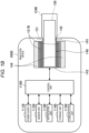
- FIG. 1A is a schematic diagram schematically illustrating a first configuration example of the inhalation device.
- an inhalation device 100A includes a power supply unit 110, a cartridge 120, and a flavor imparting cartridge 130.
- the power supply unit 110 includes a power supply 111A, a sensor unit 112A, a notification unit 113A, a storage unit 114A, a communication unit 115A, and a control unit 116A.
- the cartridge 120 includes a heating unit 121A, a liquid guide portion 122, and a liquid storage portion 123.
- the flavor imparting cartridge 130 includes a flavor source 131 and a mouthpiece 124A.
- An air flow path 180 is formed in the cartridge 120 and the flavor imparting cartridge 130.
- the power supply 111A stores electric power.
- the power supply 111A supply the electric power to each component of the inhalation device 100A under control of the control unit 116A.
- the power supply 111A may be implemented by, for example, a rechargeable battery such as a lithium-ion secondary battery.
- the sensor unit 112A acquires various types of information related to the inhalation device 100A.
- the sensor unit 112A is implemented by a pressure sensor such as a condenser microphone, a flow rate sensor, a temperature sensor, or the like, and acquires a value associated with inhalation of the user.
- the sensor unit 112A is implemented by an input device that functions as an input unit for receiving an input of information (for example, various instructions) from the user, such as an operation button (for example, an operation button 13 to be described later) or a switch.
- the sensor unit 112A includes a pressure sensor (also referred to as a "puff sensor”) that detects a change in a pressure (that is, an internal pressure) inside the inhalation device 100A caused by the inhalation of the user.
- the sensor unit 112A may include a flow rate sensor that detects a flow rate generated by the inhalation of the user, and a temperature sensor (also referred to as a "puff thermistor”) that detects a temperature of the heating unit 121A or around the heating unit 121A.
- the sensor unit 112A may include a base material detection sensor that detects an attachment state of the cartridge 120 and/or the flavor imparting cartridge 130.
- the base material detection sensor is implemented by, for example, a sensor that detects an electrostatic capacity, an inductance, or a pressure inside the inhalation device 100A that changes depending on whether the cartridge 120 or the like is attached, and detects, based on a detection result of the sensor, whether the cartridge 120 or the like is attached.
- the base material detection sensor may be implemented by an optical sensor such as a reflective photosensor, and may optically detect whether the cartridge 120 or the like is attached.
- the sensor unit 112A may include a mouthpiece detection sensor that detects an attachment state of the mouthpiece 124A.
- the mouthpiece detection sensor is implemented by, for example, a sensor that detects an electrostatic capacity, or a pressure inside the inhalation device 100A that changes depending on whether the mouthpiece 124A is attached, and detects, based on a detection result of the sensor, whether the mouthpiece 124A is attached.
- the mouthpiece detection sensor may detect whether the mouthpiece 124A is attached based on the presence or absence of electrical contact between an electrode provided in the inhalation device 100A (for example, a main body portion 10 to be described later) and an electrode provided in the mouthpiece 124A.
- the mouthpiece detection sensor may be implemented by an optical sensor such as a reflective photosensor, and may optically detect whether the mouthpiece 124A is attached.
- information indicating whether the mouthpiece 124A is attached may be input by the user, and the sensor unit 112A may detect whether the mouthpiece 124A is attached based on the information received from the user.
- the sensor unit 112A may include a cap detection sensor that detects an attachment state of a cap 20 to be described later.
- the cap detection sensor is implemented by, for example, a sensor that detects the electrostatic capacity that changes depending on whether the cap 20 is attached to the inhalation device 100A (for example, the main body portion 10 to be described later), and detects, based on a detection result of the sensor, whether the cap 20 is attached.
- the cap detection sensor may detect whether the cap 20 is attached based on the presence or absence of electrical contact between an electrode provided in the inhalation device 100A (for example, the main body portion 10 to be described later) and an electrode provided in the cap 20.
- the cap detection sensor may be implemented by an optical sensor such as a reflective photosensor, and may optically detect whether the cap 20 is attached.
- information indicating whether the cap 20 is attached may be input by the user, and the sensor unit 112A may detect whether the cap 20 is attached based on the information received from the user.
- the notification unit 113A notifies the user of information.
- Examples of the notification unit 113A include a light emitting device (for example, a light emitting unit 14 to be described later) that emits light, a display device (for example, a display unit 15 to be described later) that displays an image, a sound output device that outputs sound, or a vibration device that vibrates.
- the storage unit 114A stores various types of information for an operation of the inhalation device 100A.
- the storage unit 114A is implemented by, for example, a nonvolatile storage medium such as a flash memory.
- the communication unit 115A is a communication interface capable of performing communication conforming to any wired or wireless communication standard.
- a communication standard for example, a standard using Wi-Fi (registered trademark), Bluetooth (registered trademark), Bluetooth Low Energy (BLE (registered trademark)), Near Field Communication (NFC), or Low Power Wide Area (LPWA) may be adopted.
- the control unit 116A functions as an arithmetic processing device and a control device, and controls overall operations in the inhalation device 100A according to various programs.
- the control unit 116A is implemented by, for example, an electronic circuit such as a central processing unit (CPU) or a microprocessor.
- the liquid storage portion 123 stores an aerosol source. That is, the cartridge 120 including the liquid storage portion 123 for storing the aerosol source is an example of a base material including the aerosol source.
- the aerosol source is atomized to generate an aerosol.
- the aerosol source is, for example, a liquid such as water or a polyhydric alcohol such as glycerin and propylene glycol.
- the aerosol source may contain a flavor component derived from tobacco or non-tobacco.
- the inhalation device 100A is a medical inhaler such as a nebulizer
- the aerosol source may include a medical agent.
- the liquid guide portion 122 guides the aerosol source, which is a liquid stored in the liquid storage portion 123, from the liquid storage portion 123 and holds the aerosol source.
- the liquid guide portion 122 is, for example, a wick formed by twisting a fibrous material such as glass fibers or a porous material such as porous ceramics. In that case, the aerosol source stored in the liquid storage portion 123 is induced by a capillary effect of the wick.
- the heating unit 121A heats the aerosol source to atomize the aerosol source to generate the aerosol.
- the heating unit 121A is implemented by a coil and wound around the liquid guide portion 122.
- the heating unit 121A generates heat, the aerosol source held by the liquid guide portion 122 is heated and atomized, and the aerosol is generated.
- the heating unit 121A generates heat when supplied with power from the power supply 111A.
- the heating unit 121A may be supplied with power when the sensor unit 112A detects that the user starts the inhalation and/or that predetermined information is input.
- the supply of power to the heating unit 121A may be stopped.
- An inhalation operation of the user with respect to the inhalation device 100A can be detected, for example, based on the fact that the pressure (internal pressure) inside the inhalation device 100A detected by the puff sensor exceeds a predetermined threshold.
- the flavor source 131 is a component for imparting the flavor component to the aerosol.
- the flavor source 131 may contain the flavor component derived from tobacco or non-tobacco.
- the air flow path 180 is a flow path of air inhaled by the user.
- the air flow path 180 has a tubular structure having an air inflow hole 181 which is an inlet of air into the air flow path 180 and an air outflow hole 182 which is an outlet of air from the air flow path 180 as both ends.
- the liquid guide portion 122 is disposed on an upstream side (a side close to the air inflow hole 181), and the flavor source 131 is disposed on a downstream side (a side close to the air outflow hole 182).
- the air flowing in from the air inflow hole 181 in response to the inhalation of the user is mixed with the aerosol generated by the heating unit 121A, passes through the flavor source 131, and is transported to the air outflow hole 182 as indicated by an arrow 190.
- a mixed fluid of the aerosol and the air passes through the flavor source 131, the flavor component contained in the flavor source 131 is imparted to the aerosol.
- the mouthpiece 124A is a member that can be held by the user in his/her mouth during the inhalation.
- the air outflow hole 182 is disposed in the mouthpiece 124A. The user can take in the mixed fluid of the aerosol and the air into the oral cavity by holding the mouthpiece 124A in his/her mouth and inhaling the mouthpiece 124A. That is, the inhalation device 100A delivers the generated aerosol to the user via the mouthpiece 124A.
- the configuration example of the inhalation device 100A has been described above. It is needless to say that the configuration of the inhalation device 100A is not limited to the above, and may adopt various configurations as exemplified below.
- the inhalation device 100A may not include the flavor imparting cartridge 130.
- the mouthpiece 124A is provided on the cartridge 120.
- the inhalation device 100A may further include a second heating unit that heats the flavor source 131.
- the second heating unit is formed in a film shape, for example, and is disposed to cover an outer periphery of the flavor imparting cartridge 130. Then, the second heating unit generates heat when being supplied with electric power from the power supply 111A, and heats the flavor imparting cartridge 130 from the outer periphery.
- a temperature of the flavor source 131 can be increased and an amount of the flavor component applied to the aerosol can be increased, as compared with a case where the second heating unit is not provided.
- the second heating unit is controlled such that an actual temperature becomes a predetermined target temperature, for example, similarly to a heating unit 121B to be described later.
- the inhalation device 100A may include a plurality of types of aerosol sources.
- a plurality of types of aerosols generated from the plurality of types of aerosol sources may be mixed in the air flow path 180 to cause a chemical reaction, thereby generating another type of aerosol.
- a method for atomizing the aerosol source is not limited to heating by the heating unit 121A.
- the method for atomizing the aerosol source may be vibratory atomization or induction heating.
- FIG. 1B is a schematic diagram schematically illustrating a second configuration example of the inhalation device.
- an inhalation device 100B according to the present configuration example includes a power supply 111B, a sensor unit 112B, a notification unit 113B, a storage unit 114B, a communication unit 115B, a control unit 116B, a heating unit 121B, an accommodating portion 140, and a heat insulating portion 144.
- the power supply 111B, the sensor unit 112B, the notification unit 113B, the storage unit 114B, the communication unit 115B, and the control unit 116B are substantially the same as the corresponding components provided in the inhalation device 100A according to the first configuration example.
- the base material detection sensor is implemented by a sensor that detects an electrostatic capacity, an inductance, or a pressure inside the inhalation device 100B that changes depending on whether a stick-type base material 150 to be described later is attached to the inhalation device 100B (for example, the main body portion 10 to be described later), and detects, based on a detection result of the sensor, whether the stick-type base material 150 is attached.
- the base material detection sensor may optically detect whether the stick-type base material 150 is attached.
- the cap detection sensor is implemented by a sensor that detects the electrostatic capacity that changes depending on whether the cap 20 is attached to the inhalation device 100B (for example, the main body portion 10 to be described later), and detects, based on a detection result of the sensor, whether the cap 20 is attached.
- the cap detection sensor may detect whether the cap 20 is attached based on the presence or absence of electrical contact between an electrode provided in the inhalation device 100B (for example, the main body portion 10 to be described later) and an electrode provided in the cap 20.
- the cap detection sensor may optically detect whether the cap 20 is attached.
- the sensor unit 112B may detect whether the cap 20 is attached based on information received from the user.
- the accommodating portion 140 has an internal space 141, and holds the stick-type base material 150 while accommodating a part of the stick-type base material 150 in the internal space 141.
- the accommodating portion 140 has an opening 142 through which the internal space 141 communicates with the outside, and holds the stick-type base material 150 inserted into the internal space 141 from the opening 142.
- the accommodating portion 140 is a cylindrical body having the opening 142 and a bottom portion 143 as a bottom surface, and defines the columnar internal space 141.
- An air flow path for supplying air to the internal space 141 is connected to the accommodating portion 140.
- An air inflow hole which is an inlet of air to the air flow path, is disposed, for example, in a side surface of the inhalation device 100.
- An air outflow hole, which is an outlet of air from the air flow path to the internal space 141 is disposed, for example, in the bottom portion 143.
- the stick-type base material 150 includes a base material portion 151.
- the base material portion 151 includes the aerosol source. That is, the stick-type base material 150 is another example of the base material including the aerosol source.
- the aerosol source contains the flavor component derived from tobacco or non-tobacco.
- the aerosol source may include a medical agent.
- the aerosol source may be a liquid such as water and polyhydric alcohols such as glycerin and propylene glycol, including the flavor component derived from tobacco or non-tobacco, or may be a solid including the flavor component derived from tobacco or non-tobacco.
- the inhalation device 100B In a state where the stick-type base material 150 is held by the accommodating portion 140, at least a part of a base material portion 151 is accommodated in the internal space 141.
- the mouthpiece 124B of the inhalation device 100B is attached to cover the stick-type base material 150 accommodated in the accommodating portion 140.
- the heat insulating portion 144 prevents heat transfer from the heating unit 121B to other components.
- the heat insulating portion 144 is made of a vacuum heat insulating material or an aerogel heat insulating material.
- the configuration example of the inhalation device 100B has been described above. It is needless to say that the configuration of the inhalation device 100B is not limited to the above, and may adopt various configurations as exemplified below.
- the heating unit 121B may be formed in a blade shape and disposed to protrude from the bottom portion 143 of the accommodating portion 140 into the internal space 141.
- the blade-shaped heating unit 121B is inserted into the base material portion 151 of the stick-type base material 150, and heats the base material portion 151 of the stick-type base material 150 from the inside.
- the heating unit 121B may be disposed to cover the bottom portion 143 of the accommodating portion 140.
- the heating unit 121B may be configured as a combination of two or more of a first heating unit covering the outer periphery of the accommodating portion 140, a blade-shaped second heating unit, and a third heating unit covering the bottom portion 143 of the accommodating portion 140.
- the accommodating portion 140 may include an opening and closing mechanism such as a hinge that opens and closes a part of an outer shell forming the internal space 141.
- the accommodating portion 140 may open and close the outer shell to sandwich and accommodate the stick-type base material 150 inserted into the internal space 141.
- the heating unit 121B may be provided at a sandwiching place in the accommodating portion 140, and may heat the stick-type base material 150 while pressing the stick-type base material 150.
- the method for atomizing the aerosol source is not limited to heating by the heating unit 121B.
- the method for atomizing the aerosol source may be induction heating.
- the inhalation device 100B at least includes an electromagnetic induction source such as a coil for generating a magnetic field, instead of the heating unit 121B.
- a susceptor that generates heat due to the induction heating may be provided in the inhalation device 100B or may be provided in the stick-type base material 150.
- the inhalation device 100B may further include the heating unit 121A, the liquid guide portion 122, the liquid storage portion 123, and the air flow path 180 according to the first configuration example, and the air flow path 180 may supply air to the internal space 141.
- the mixed fluid of the aerosol and the air generated by the heating unit 121A flows into the internal space 141, is further mixed with the aerosol generated by the heating unit 121B, and reaches the oral cavity of the user.
- an external configuration example of an inhalation device 100 (100A, 100B) of the present embodiment will be described.
- the inhalation device 100 is described as being the inhalation device 100B illustrated in FIG. 1B , but the present invention is not limited thereto, and the same can be applied to a case where the inhalation device 100 is the inhalation device 100A illustrated in FIG. 1A .
- FIG. 2A is a front view of the inhalation device 100B in a state where the cap 20 is removed therefrom.
- FIG. 2B is a front view of the inhalation device 100B in a state where the cap 20 is attached thereto.
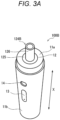
- FIG. 3A is a perspective view of the inhalation device 100B in a state where the cap 20 is removed therefrom.
- FIG. 3B is a perspective view of the inhalation device 100B in a state where the mouthpiece 124B and the stick-type base material 150 are removed therefrom.
- the inhalation device 100B includes the main body portion 10 having a rod shape extending along a predetermined direction (hereinafter also referred to as a "longitudinal direction X").
- the main body portion 10 is configured to accommodate, inside a main body housing 11 having a cylindrical shape, components such as the power supply 111B, the sensor unit 112B, the notification unit 113B, the storage unit 114B, the communication unit 115B, the control unit 116B, and the heating unit 121B of the inhalation device 100B illustrated in FIG. 1B .
- the main body portion 10 is not limited to the rod shape, and may have, for example, a rectangular parallelepiped shape, an egg-shaped shape, or an elliptical shape.
- the mouthpiece 124B is attached to a top portion 11a positioned on one end side in the longitudinal direction X of the main body portion 10. As illustrated in FIGS. 3A and 3B , the mouthpiece 124B includes a base portion 125 that can be fitted to a mouthpiece holder 12 provided on the top portion 11a, and a cylindrical inhalation port portion 126 that protrudes from the base portion 125.
- the mouthpiece 124B is attached to the main body portion 10 by the base portion 125 being fitted to the mouthpiece holder 12 of the main body portion 10 in a state where the inhalation port portion 126 faces a side opposite to the main body portion 10. Further, when the mouthpiece 124B attached to the main body portion 10 is pulled by a force equal to or greater than a certain force in a direction opposite to the main body portion 10, the base portion 125 is separated from the mouthpiece holder 12. Accordingly, the mouthpiece 124B can be removed from the main body portion 10. In this manner, the main body portion 10 is configured such that the mouthpiece 124B is detachable (that is, mounted).
- the top portion 11a is further provided with an opening 142.
- the opening 142 is provided to overlap the mouthpiece holder 12 when viewed from the longitudinal direction X.
- the opening 142 is covered by the mouthpiece 124B and is difficult for the user to see. Meanwhile, by removing the mouthpiece 124B from the main body portion 10, the user can easily insert the stick-type base material 150 into the accommodating portion 140 in the main body portion 10 from the opening 142 or easily remove the stick-type base material 150 accommodated in the accommodating portion 140.
- the cap 20 that covers the mouthpiece 124B attached to the main body portion 10 can be further mounted to the top portion 11a.
- the mouthpiece 124B can be prevented from being exposed to the outside, and the mouthpiece 124B can be kept hygienically.
- a charging terminal electrically connectable to an external power supply, for example, is provided in a bottom portion 11b positioned on the other end side in the longitudinal direction X of the main body portion 10.
- a USB terminal for example, a USB Type-C terminal
- the user can charge the power supply 111B using electric power of the external power supply by connecting the inhalation device 100B to the external power supply via the charging terminal.
- the charging terminal may be used at the time of connecting the inhalation device 100B and an external device (for example, another device such as a smartphone of the user) of the inhalation device 100B in a wired manner.
- the operation button 13 and the light emitting unit 14 are provided on a side surface of the main body portion 10 at a position between the top portion 11a and the bottom portion 11b.
- the operation button 13 is an example of an operation unit that can be pressed down by the user, and may be implemented by a push-button-type operation button that the user can physically press down.
- the operation button 13 may be implemented by an electrostatic-capacity-type or resistance-film-type touch sensor.
- the light emitting unit 14 is an example of a light emitting unit that emits light, and for example, includes one or more light emitting elements.
- a light emitting diode LED
- the light emitting unit 14 includes a plurality of LEDs having different emission colors, and is configured to emit light in a plurality of emission colors including blue, yellow, and red.
- the light emitting unit 14 emits light in a predetermined light emitting mode under control of the control unit 116B, thus notifying the user of predetermined information.
- the light emitting mode can be, for example, a light emission color, but is not limited thereto, and may be, for example, an intensity of lighting (in other words, brightness) or a lighting pattern (for example, blinking at a predetermined time interval).
- Examples of the notification performed by the light emitting unit 14 include a first notification, a second notification, and a third notification to be described later.
- a control unit 116 may operate the inhalation device 100 based on an input from the user.
- the control unit 116 in response to a heating start instruction from the user, causes a heating unit 121 (121A and 121B) to generate the aerosol.
- an inhaler that generates a substance to be inhaled by a user, such as the inhalation device 100, in order to prevent an occurrence of inconvenience caused by misuse by a child of a mischievous age (for example, an infant and a young child who are three years old or younger.
- a so-called “child resistance function" (hereinafter also referred to as an "CR function")" may be implemented.
- a predetermined operation such as generating the substance to be inhaled is performed only when a predetermined operation is performed on the operation unit (for example, an operation button) provided in the inhaler.
- the control unit 116B can detect that the stick-type base material 150 is attached at the time t3.
- FIG. 5 is a diagram illustrating a second example of the specific operations of the inhalation device 100B.
- the second example is an example of a case where the control unit 116B does not perform the heating control on the heating unit 121B corresponding to the heating start operation even if the heating start operation is performed (that is, the heating start instruction is received).
- the control unit 116B does not perform the heating control on the heating unit 121B corresponding to the heating start operation even if the heating start operation is performed (that is, the heating start instruction is received).
- the user presses down the operation button 13 from the time t5 without going through a procedure of removing the mouthpiece 124B at the time t2 illustrated in FIG. 4 , attaching the stick-type base material 150 at the time t3, and attaching the mouthpiece 124B at the time t4.
- the detection state of the stick-type base material 150 at the time t6 at which it is determined that the heating start operation is performed is "non-detection".
- the control unit 116B does not perform the heating control on the heating unit 121B corresponding to the heating start operation. That is, in the example illustrated in FIG. 5 , an off state of the heating control on the heating unit 121B is also maintained after the time t6.
- the control unit 116B may turn off the power supply of the inhalation device 100B at that time.
- the control unit 116B can prevent the generation of aerosol that uses the heating unit 121B. Accordingly, it is possible to prevent the generation of aerosol in response to an input from the user, such as a child, who does not grasp the correct use method of the inhalation device 100B such as mounting the stick-type base material 150 and the mouthpiece 124B to the main body portion 10. Accordingly, the occurrence of inconvenience caused by the misuse by such a user can be prevented.
- the user removes the mouthpiece 124B at the time t2 illustrated in FIG. 4 , and attaches the stick-type base material 150 at the time t3, but presses down the operation button 13 from the time t5 without performing the attachment of the mouthpiece 124B at the time t4.
- the detection state of the mouthpiece 124B at the time t6 at which it is determined that the heating start operation is performed is "non-detection".
- the control unit 116B does not perform the heating control on the heating unit 121B corresponding to the heating start operation. That is, in the example illustrated in FIG. 6 , an off state of the heating control on the heating unit 121B is also maintained after the time t6.
- the control unit 116B can prevent the generation of aerosol that uses the heating unit 121B. Accordingly, it is possible to prevent the generation of aerosol in response to an input from the user, such as a child, who does not grasp the correct use method of the inhalation device 100B such as mounting the stick-type base material 150 and the mouthpiece 124B to the main body portion 10. Accordingly, the occurrence of inconvenience caused by the misuse by such a user can be prevented.
- the user needs to follow a procedure that includes a plurality of steps, such as (1) attachment of the stick-type base material 150, (2) attachment of the mouthpiece 124B, and (3) the heating start operation.
- a procedure that includes a plurality of steps, such as (1) attachment of the stick-type base material 150, (2) attachment of the mouthpiece 124B, and (3) the heating start operation.
- the user is forced to overcome many hurdles before starting to smoke. Therefore, a robust CR function capable of further preventing the misuse by the user, such as a child who does not grasp the correct use method of the inhalation device 100B can be realized.
- control unit 116B may cause the notification unit 113B to perform the first notification when the stick-type base material 150 is mounted to the main body portion 10, cause the notification unit 113B to perform the second notification when the mouthpiece 124B is mounted to the main body portion 10, and cause the notification unit 113B to perform the third notification when the heating start operation is received (that is, the heating start instruction is received). Accordingly, since the notifications can be performed in conjunction with the mounting of the stick-type base material 150 and the mouthpiece 124B to the main body portion 10 and the heating start operation, it is possible for the user to grasp a progress of a procedure up when the aerosol can be inhaled, and the convenience of inhalation device 100B can be improved.
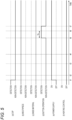
- FIG. 7 is a diagram illustrating a fourth example of the specific operation of the inhalation device 100B.
- the first notification, the second notification, and the third notification are performed by the light emitting unit 14 provided in the notification unit 113B.
- portions different from the description of FIG. 4 will be mainly described, and description of portions common to the description of FIG. 4 will be omitted or simplified as appropriate.
- the control unit 116B when it is detected that the stick-type base material 150 is attached to the main body portion 10, the control unit 116B causes the light emitting unit 14 to emit red light (refer to from the time t3 to the time t4), as the first notification.
- the control unit 116B causes the light emitting unit 14 to emit blue light (refer to from the time t6 to the time t7), as the third notification.
- the control unit 116B may further perform a fourth notification different from the first notification, the second notification, and the third notification when the power supply of the inhalation device 100B is turned on. Accordingly, it is possible to notify the user that the power supply of the inhalation device 100B is turned on. As an example, the control unit 116B may cause the light emitting unit 14 to emit white light, as the fourth notification.
- control unit 116B can cause the light emitting unit 14 to perform the first notification when the stick-type base material 150 is mounted to the main body portion 10, cause the light emitting unit 14 to perform the second notification when the mouthpiece 124B is mounted to the main body portion 10, and cause the light emitting unit 14 to perform the third notification when the heating start operation is received (that is, the heating start instruction is received). Accordingly, since the notifications can be performed in conjunction with the mounting of the stick-type base material 150 and the mouthpiece 124B to the main body portion 10 and the heating start instruction, it is possible for the user to grasp a progress of the procedure up when the aerosol can be inhaled, and the convenience of inhalation device 100B can be improved.
- the first notification, the second notification, and the third notification can be made intuitive and easy-to-understand for the user to understand.
- the first notification, the second notification, and the third notification are different from one another in the emission color of the light emitting unit 14, but the present invention is not limited thereto.
- examples of a case where the first notification, the second notification, and the third notification are different from one another except for the light emission color of the light emitting unit 14 will be described.
- FIG. 8 is a diagram illustrating another example of the light emitting unit 14.
- the light emitting unit 14 includes a first light emitting element 14a, a second light emitting element 14b, and a third light emitting element 14c.
- LEDs may be adopted as the first light emitting element 14a, the second light emitting element 14b, and the third light emitting element 14c.
- Emission colors of the first light emitting element 14a, the second light emitting element 14b, and the third light emitting element 14c may be the same or different.
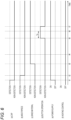
- FIG. 9 is a diagram illustrating a fifth example of the specific operations of the inhalation device 100B.
- portions different from the description of FIG. 7 will be mainly described, and description of portions common to the description of FIG. 7 will be omitted or simplified as appropriate.
- the first notification, the second notification, and the third notification are different from one another in the number of light emitting elements that emit light among the plurality of light emitting elements in the light emitting unit 14.
- the control unit 116B causes two light emitting elements (for example, the first light emitting element 14a and the second light emitting element 14b) among the light emitting elements in the light emitting unit 14 to emit light (refer to from the time t4 to the time t5), as the second notification.
- the control unit 116B causes three light emitting elements among the light emitting elements in the light emitting unit 14 to emit light (refer to from the time t6 to the time t7), as the third notification.
- step S3 determines whether attachment of the stick-type base material 150 to the main body portion 10 is detected. If the attachment of the stick-type base material 150 to the main body portion 10 is not detected (step S3: No), the control unit 116B determines, for example, whether a timeout occurs after a predetermined time (for example, 1 [min]) has elapsed since the processing of step S3 is started (step S4). If the timeout does not occur (step S4: No), the control unit 116B repeats the processing of step S3 until the timeout occurs.
- a timeout for example, 1 [min]
- step S7 the control unit 116B ends the series of processing illustrated in FIG. 12 . Accordingly, for example, after the attachment of the stick-type base material 150 is detected, the heating control on the heating unit 121B may not be performed if the mouthpiece 124B is not attached within a predetermined time. Accordingly, it is possible to prevent the occurrence of inconvenience caused by misuse of the user such as a child who does not grasp the correct use method of the inhalation device 100B.
- step S9 When it is determined that the heating start operation is performed (step S9: Yes), the control unit 116B causes the notification unit 113B (for example, the light emitting unit 14) to perform the third notification (step S11), starts the heating control on the heating unit 121B (step S12), and ends the series of processing illustrated in FIG. 12 .
- the notification unit 113B for example, the light emitting unit 14
- the control unit 116 may activate the inhalation device 100 in response to reception of an input of an activation instruction from the user. Then, after the activation of the inhalation device 100, the control unit 116 may cause the heating unit 121 to generate the aerosol in response to reception of the heating start instruction (for example, the heating start operation).
- the heating start instruction for example, the heating start operation
- the activation instruction can be a predetermined operation instructing activation to the inhalation device 100 (hereinafter also referred to as an "activation operation").
- the activation operation can be an operation using the operation button 13, and can be, for example, long-pressing the operation button 13 when the power supply of the inhalation device 100 is turned off.
- the activation operation may be a plurality of times of press-down of the operation button 13 when the power supply of the inhalation device 100 is turned off.
- control unit 116 may vary severity of the hurdles for activating the functions. Accordingly, the inhalation device 100 with higher convenience can be provided.
- FIG. 14 is a diagram illustrating an example of conditions for generating the aerosol by the heating unit 121 and conditions for communicating with the external device via the communication unit 115.
- the control unit 116 requires all of the mounting of the base material including the aerosol source, the mounting of the mouthpiece 124, and the operation using the operation button 13 (for example, the heating start operation described above) in order to generate the aerosol by the heating unit 121. Accordingly, the generation of the aerosol by the heating unit 121 can be prevented more firmly with respect to the user such as a child who does not grasp the correct use method of the inhalation device 100.
- the communication between the inhalation device 100 and the external device can realize, for example, update of a control program of the inhalation device 100 (for example, the heating profile, a lighting control program of the LED of the light emitting unit 14, a charge or discharge control program of the power supply 111, and the like), various authentications, and transmission and reception of various data related to smoking using the inhalation device 100. Accordingly, the inhalation device 100 with higher convenience can be provided.
- a control program of the inhalation device 100 for example, the heating profile, a lighting control program of the LED of the light emitting unit 14, a charge or discharge control program of the power supply 111, and the like
- the control unit 116 may cause the heating unit 121 to generate the aerosol if the base material and the mouthpiece 124 are mounted, and may allow the communication with the external device if at least one of the base material and the mouthpiece 124 is not mounted.
- a control method of the inhalation device 100 described in the above embodiment can be achieved by executing a program prepared in advance on a computer (a processor).
- the program is stored in a computer-readable storage medium and is executed by being read from the storage medium. Further, the program may be provided in a form of being stored in a non-transitory storage medium such as a flash memory, and may be provided via a network such as the Internet.
- the computer that executes the program can be, for example, a component provided in the inhalation device 100 (for example, the CPU of the inhalation device 100), but is not limited thereto, and may be a component provided in another device (for example, a smartphone or a server) capable of communicating with the inhalation device 100.
- the aerosol can be generated and a decrease in convenience of the inhalation device can be prevented.
- the mouthpiece mounted to the main body portion can be covered with the cap and the mouthpiece can be kept hygienically.
- the user can activate the inhalation device simply by removing the cap mounted on the main body portion, and the convenience of the inhalation device is improved.
- the notification can be performed in conjunction with the mounting of the base material and the mouthpiece to the main body portion and the heating start instruction, it is possible for the user to grasp a progress of a procedure up when the aerosol can be inhaled, and the convenience of inhalation device can be improved.
- the first notification, the second notification, and the third notification can be made intuitive and easy-to-understand for the user.
- the first notification, the second notification, and the third notification can be made intuitive and easy-to-understand for the user.
- the first notification, the second notification, and the third notification can be made intuitive and easy-to-understand for the user.
- the first notification, the second notification, and the third notification can be made intuitive and easy-to-understand for the user.
- control unit is configured to allow the inhalation device to perform another operation different from the generation of the aerosol using the heating unit when at least one of the base material and the mouthpiece is not mounted on the main body portion.
- the base material since the base material does not include the inhalation port portion, the base material can be simplified or reduced in size, and the number of components and a necessary material constituting the base material can be reduced.
- a control method to be performed by a computer for controlling an operation of an inhalation device (inhalation device 100, 100A, 100B) that generates an aerosol from a base material (cartridge 120, flavor imparting cartridge 130, stick-type base material 150) including an aerosol source and delivers the generated aerosol to a user via a mouthpiece (mouthpiece 124, 124A, 124B), the inhalation device including:
- the inhalation device it is possible to prevent the inhalation device from operating in response to the input from the user such as a child who does not grasp the correct use method of the inhalation device such as mounting the base material including the aerosol source and the mouthpiece to the main body portion. Accordingly, it is possible to prevent the occurrence of inconvenience caused by misuse by the user who does not grasp the correct use method of the inhalation device.
- a program to be executed by a computer for controlling an operation of an inhalation device (inhalation device 100, 100A, 100B) that generates an aerosol from a base material (cartridge 120, flavor imparting cartridge 130, stick-type base material 150) including an aerosol source and delivers the generated aerosol to a user via a mouthpiece (mouthpiece 124, 124A, 124B), the inhalation device including:
- the inhalation device it is possible to prevent the inhalation device from operating in response to the input from the user such as a child who does not grasp the correct use method of the inhalation device such as mounting the base material including the aerosol source and the mouthpiece to the main body portion. Accordingly, it is possible to prevent the occurrence of inconvenience caused by misuse by the user who does not grasp the correct use method of the inhalation device.
Landscapes
- Engineering & Computer Science (AREA)
- Human Computer Interaction (AREA)
- Health & Medical Sciences (AREA)
- Child & Adolescent Psychology (AREA)
- General Health & Medical Sciences (AREA)
- Containers And Packaging Bodies Having A Special Means To Remove Contents (AREA)
Applications Claiming Priority (1)
| Application Number | Priority Date | Filing Date | Title |
|---|---|---|---|
| PCT/JP2022/031136 WO2024038530A1 (ja) | 2022-08-17 | 2022-08-17 | 吸引装置、制御方法、及びプログラム |
Publications (1)
| Publication Number | Publication Date |
|---|---|
| EP4573941A1 true EP4573941A1 (en) | 2025-06-25 |
Family
ID=89941562
Family Applications (1)
| Application Number | Title | Priority Date | Filing Date |
|---|---|---|---|
| EP22955704.6A Pending EP4573941A1 (en) | 2022-08-17 | 2022-08-17 | Inhalation device, control method, and program |
Country Status (6)
| Country | Link |
|---|---|
| US (1) | US20250185719A1 (https=) |
| EP (1) | EP4573941A1 (https=) |
| JP (1) | JPWO2024038530A1 (https=) |
| KR (1) | KR20250038713A (https=) |
| CN (1) | CN119698243A (https=) |
| WO (1) | WO2024038530A1 (https=) |
Family Cites Families (9)
| Publication number | Priority date | Publication date | Assignee | Title |
|---|---|---|---|---|
| EP3389422A1 (en) | 2015-12-18 | 2018-10-24 | JT International SA | Inhaler device and method of operating same |
| KR20240126878A (ko) * | 2016-07-25 | 2024-08-21 | 필립모리스 프로덕츠 에스.에이. | 히터 관리 |
| US10759554B2 (en) | 2017-02-02 | 2020-09-01 | Rai Strategic Holdings, Inc. | Dispenser unit for aerosol precursor |
| GB201717498D0 (en) * | 2017-10-24 | 2017-12-06 | British American Tobacco Investments Ltd | Aerosol provision device |
| TW201929702A (zh) * | 2017-12-29 | 2019-08-01 | 瑞士商傑太日煙國際股份有限公司 | 用於一蒸氣產生裝置之加熱總成 |
| JP2019205405A (ja) * | 2018-05-30 | 2019-12-05 | 日本電産コパル株式会社 | タバコ加熱装置 |
| JP7170118B2 (ja) * | 2019-02-27 | 2022-11-11 | 日本たばこ産業株式会社 | 吸引装置、吸引装置の制御装置、情報処理方法及びプログラム |
| US12185752B2 (en) * | 2020-07-21 | 2025-01-07 | Rai Strategic Holdings, Inc. | Case for aerosol generation device |
| US11789476B2 (en) * | 2021-01-18 | 2023-10-17 | Altria Client Services Llc | Heat-not-burn (HNB) aerosol-generating devices including intra-draw heater control, and methods of controlling a heater |
-
2022
- 2022-08-17 EP EP22955704.6A patent/EP4573941A1/en active Pending
- 2022-08-17 WO PCT/JP2022/031136 patent/WO2024038530A1/ja not_active Ceased
- 2022-08-17 CN CN202280099098.3A patent/CN119698243A/zh active Pending
- 2022-08-17 JP JP2024541336A patent/JPWO2024038530A1/ja active Pending
- 2022-08-17 KR KR1020257004802A patent/KR20250038713A/ko active Pending
-
2025
- 2025-02-14 US US19/053,705 patent/US20250185719A1/en active Pending
Also Published As
| Publication number | Publication date |
|---|---|
| WO2024038530A1 (ja) | 2024-02-22 |
| US20250185719A1 (en) | 2025-06-12 |
| KR20250038713A (ko) | 2025-03-19 |
| CN119698243A (zh) | 2025-03-25 |
| JPWO2024038530A1 (https=) | 2024-02-22 |
Similar Documents
| Publication | Publication Date | Title |
|---|---|---|
| US20230000172A1 (en) | Inhaling device | |
| JP7578706B2 (ja) | 吸引器用の電源ユニット | |
| US20230000152A1 (en) | Inhaling device, control method, and non-transitory computer readable medium | |
| EP4573941A1 (en) | Inhalation device, control method, and program | |
| CN118922095A (zh) | 气溶胶生成装置、控制方法以及程序 | |
| CN118317710A (zh) | 吸取装置 | |
| EP4573944A1 (en) | Inhalation device, control method, and program | |
| EP4635341A1 (en) | Inhalation device, control method, and program | |
| EP4573945A1 (en) | Inhalation device, control method, and program | |
| CN118265469A (zh) | 吸取装置 | |
| WO2023089754A1 (ja) | 吸引装置 | |
| EP4573942A1 (en) | Inhalation device, control method, and program | |
| EP4635340A1 (en) | Inhalation device, control method, and program | |
| EP4635342A1 (en) | Inhalation device, control method, and program | |
| US20240324696A1 (en) | Aerosol generation device and information display device | |
| EP4613138A1 (en) | Information processing device, inhalation system, and information presentation method | |
| CN118922096A (zh) | 气溶胶生成装置、控制方法以及程序 | |
| EA051686B1 (ru) | Блок питания для ингалятора | |
| EA048460B1 (ru) | Блок питания для ингалятора | |
| WO2024047705A1 (ja) | 吸引装置、基材、及び吸引システム | |
| CN121532083A (zh) | 气溶胶产生系统、控制方法和程序 | |
| CN119072254A (zh) | 气溶胶生成装置、控制方法以及程序 |
Legal Events
| Date | Code | Title | Description |
|---|---|---|---|
| STAA | Information on the status of an ep patent application or granted ep patent |
Free format text: STATUS: THE INTERNATIONAL PUBLICATION HAS BEEN MADE |
|
| PUAI | Public reference made under article 153(3) epc to a published international application that has entered the european phase |
Free format text: ORIGINAL CODE: 0009012 |
|
| STAA | Information on the status of an ep patent application or granted ep patent |
Free format text: STATUS: REQUEST FOR EXAMINATION WAS MADE |
|
| 17P | Request for examination filed |
Effective date: 20250217 |
|
| AK | Designated contracting states |
Kind code of ref document: A1 Designated state(s): AL AT BE BG CH CY CZ DE DK EE ES FI FR GB GR HR HU IE IS IT LI LT LU LV MC MK MT NL NO PL PT RO RS SE SI SK SM TR |
|
| DAV | Request for validation of the european patent (deleted) | ||
| DAX | Request for extension of the european patent (deleted) |