EP4572104A1 - Elektrische maschine und fahrzeug mit verbessertem kühlsystem - Google Patents
Elektrische maschine und fahrzeug mit verbessertem kühlsystem Download PDFInfo
- Publication number
- EP4572104A1 EP4572104A1 EP24218411.7A EP24218411A EP4572104A1 EP 4572104 A1 EP4572104 A1 EP 4572104A1 EP 24218411 A EP24218411 A EP 24218411A EP 4572104 A1 EP4572104 A1 EP 4572104A1
- Authority
- EP
- European Patent Office
- Prior art keywords
- cooling
- electric machine
- stator
- section
- cooling system
- Prior art date
- Legal status (The legal status is an assumption and is not a legal conclusion. Google has not performed a legal analysis and makes no representation as to the accuracy of the status listed.)
- Pending
Links
Images


Classifications
-
- H—ELECTRICITY
- H02—GENERATION; CONVERSION OR DISTRIBUTION OF ELECTRIC POWER
- H02K—DYNAMO-ELECTRIC MACHINES
- H02K5/00—Casings; Enclosures; Supports
- H02K5/04—Casings or enclosures characterised by the shape, form or construction thereof
- H02K5/20—Casings or enclosures characterised by the shape, form or construction thereof with channels or ducts for flow of cooling medium
- H02K5/203—Casings or enclosures characterised by the shape, form or construction thereof with channels or ducts for flow of cooling medium specially adapted for liquids, e.g. cooling jackets
-
- H—ELECTRICITY
- H02—GENERATION; CONVERSION OR DISTRIBUTION OF ELECTRIC POWER
- H02K—DYNAMO-ELECTRIC MACHINES
- H02K7/00—Arrangements for handling mechanical energy structurally associated with dynamo-electric machines, e.g. structural association with mechanical driving motors or auxiliary dynamo-electric machines
- H02K7/003—Couplings; Details of shafts
-
- H—ELECTRICITY
- H02—GENERATION; CONVERSION OR DISTRIBUTION OF ELECTRIC POWER
- H02K—DYNAMO-ELECTRIC MACHINES
- H02K9/00—Arrangements for cooling or ventilating
- H02K9/19—Arrangements for cooling or ventilating for machines with closed casing and closed-circuit cooling using a liquid cooling medium, e.g. oil
-
- H—ELECTRICITY
- H02—GENERATION; CONVERSION OR DISTRIBUTION OF ELECTRIC POWER
- H02K—DYNAMO-ELECTRIC MACHINES
- H02K9/00—Arrangements for cooling or ventilating
- H02K9/19—Arrangements for cooling or ventilating for machines with closed casing and closed-circuit cooling using a liquid cooling medium, e.g. oil
- H02K9/20—Arrangements for cooling or ventilating for machines with closed casing and closed-circuit cooling using a liquid cooling medium, e.g. oil wherein the cooling medium vaporises within the machine casing
Definitions
- the invention relates to an electric machine, which comprises a machine housing, a stator fixedly arranged in the machine housing, a rotor shaft and a rotor mounted on the rotor shaft, by which the rotor is rotatably arranged in the machine housing around a rotor axis.
- the stator comprises a stator lamination stack and stator windings arranged therein, wherein the stator windings comprise a stack section, in which they run within the stator lamination stack, and stator winding heads, where they run out of the stack section, for example in a bow shape.
- the machine housing comprises a first cooling system based on a first cooling fluid around the stator lamination stack.
- the invention relates to a vehicle, driven by an electric machine of the above kind.
- An electric machine and a vehicle of the above kinds are generally known. Often, an electric machine has to be cooled, lubricated and shall be protected against oxidation. However, these different functions have very specific demands, and providing the same at a high level at the same time is hard to achieve. So, usually a tradeoff between the functions is done, what also means that often the potential of an electric machine is not fully exploited.
- an object of the invention is to provide an improved electric machine and an improved vehicle.
- a solution shall be proposed, which allows for cooling and lubrication of an electric machine as well as for avoiding of oxidation in the interior of the same.
- the machine housing additionally comprises a separate second cooling system based on a separate second cooling fluid, wherein the separate second cooling system comprises spray nozzles or bores, which are directed towards at least one of the stator winding heads.
- the spray nozzles or bores can be directed towards just one of the stator winding heads or to both stator winding heads.
- the object of the invention is also solved by a vehicle comprising an electric machine of the above kind which is designed to propel the vehicle.
- the first cooling system of the electric machine can be part of a first cooling circuit of the vehicle
- the second cooling system can be part of a separate second cooling circuit of the vehicle.
- the functions of cooling, lubrication and oxidation protection can be provided at a very high level at the same time.
- the first cooling fluid can be water based and the second cooling fluid can be oil based.
- the thermal capacity of a water based cooling fluid is much higher than the thermal capacity of oil. Accordingly, also a cooling power of the first cooling system is higher than a cooling power of the second cooling system in this case.
- the machine housing can comprise a tube like section around the stator and end sections closing the tube like section, wherein the machine housing in the tube like section comprises
- tube section spray nozzles or bores are directed radially inwards and spray the second cooling fluid on a radially outer side of the stator winding head(s).
- the second cooling system in at least one of the end sections can comprise a cooling channel and end section spray nozzles or bores hydraulically connected thereto, which are directed towards at least one of the stator winding heads.
- end section spray nozzles or bores are provided, which are directed axially inwards and spray the second cooling fluid on a front face of the stator winding head(s). Accordingly, cooling can be improved even more.
- the second cooling system can comprise an axial central shaft bore in the rotor shaft and rotor shaft spray nozzles or bores hydraulically connected thereto, which are directed towards at least one of the stator winding heads. Accordingly, the rotor shaft spray nozzles or bores are directed radially outwards and spray the second cooling fluid on a radially inner side of the stator winding head(s), wherein a rotation of the rotor supports distribution of second cooling fluid.
- the second cooling system can also be used for cooling the rotor.
- the first cooling channel runs axially or helically and second channel in particular forms a closed ring.
- one of the end sections is one part with the tube like section both forming a pot like section, whereas in another embodiment, the tube like section and the end sections are separate parts. That means, for the first variant just one additional bearing shield is needed, whereas two bearing shields are needed for the second variant.
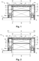
- Fig 1 shows a half sectional view of an electric machine 1, which comprises a machine housing 2a, a stator 3 fixedly arranged in the machine housing 2a, a rotor shaft 4 and a rotor 5 mounted on the rotor shaft 4, by which the rotor 5 is rotatably arranged in the machine housing 2a around a rotor axis A.
- the stator 3 comprises a stator lamination stack 6 and stator windings 7 arranged therein.
- the rotor 5 comprises a rotor lamination stack 8, in which rotor windings or rotor magnets can be arranged (not shown).
- the stator windings 7 comprise a stack section B, in which they run within the stator lamination stack 6, and stator winding heads C, C', where they run out of the stack section B and where they can have a bow shape.
- the electric machine 1 in the machine housing 2a comprises a first cooling system 9 based on a first cooling fluid around the stator lamination stack 6, and a separate second cooling system 10, 10' based on a separate second cooling fluid.
- the separate second cooling system 10, 10' runs over the entire circumference of the machine housing 2a.
- the separate second cooling system 10, 10' comprises spray nozzles or bores 11, 11', which are directed towards both stator winding heads C, C'.
- the spray nozzles or bores 11, 11' are directed radially inwards towards both stator winding heads C, C'.
- Spray jets 12 indicate that the second cooling fluid is sprayed on a radially outer side of the stator winding heads C, C'.
- the spray nozzles or bores 11, 11' are distributed all over the entire circumference of the machine housing 2a, in particular, an inner housing 13a.
- the machine housing 2a in detail comprises an inner housing part 13a and an outer housing part 14a, which is located radially outwards of the inner housing part 13a. Moreover, the machine housing 2a comprises a bearing shield 15, wherein bearings 16a, 16b for supporting the rotor shaft 4 are arranged in the outer housing part 14a and in the bearing shield 15.
- the machine housing 2a additionaly comprises a first cooling channel 17 and second cooling channels 18, 18'.
- the first cooling channel 17 is part of the first cooling system 9 and formed between the inner housing part 13a and the outer housing part 14a.
- the second cooling channels 18, 18' are part of the second cooling system 10, 10' and formed between the inner housing part 13a and the outer housing part 14a as well. Additionally, the second cooling channels 18, 18' are hydraulically connected to the spray nozzles or bores 11, 11'.
- the first cooling fluid can be water based and the second cooling fluid can be oil based.
- the first cooling fluid can be water based and the second cooling fluid can be oil based.
- the stator winding heads C, C' can be cooled and a lubricant can be brought into the interior of the electric machine 1.
- the thermal capacity of a water based cooling fluid is much higher than the thermal capacity of oil.
- Fig. 2 now shows another example of an electric machine 1b, which is similar to the electric machine 1a shown in Fig. 1 .
- the second cooling system 10 additionally comprises a cooling channel 18" and end section spray nozzles or bores 19 hydraulically connected thereto, which are directed towards at least one of the stator winding heads C, C'.
- the end section spray nozzles or bores 19 are directed axially inwards and spray the second cooling fluid on a front face of the stator winding head C.
- the machine housing 2a, 2b of the electric machine 1a, 1b can comprise a tube like section D around the stator 3 and end sections E1, E2 closing the tube like section D, wherein the inner housing part 13a and the outer housing part 14a preferably are part of the tube like section D, like this is depicted in Fig. 2 .
- the cooling channel 18" is solely arranged in the end section E1. However, there may also be an additional cooling channel 18" in the end section E2.
- one of the end sections E1, E2 (the end section E1) is one part with the tube like section D both forming a pot like section.
- the tube like section D and the end sections E1, E2 may be separate parts, meaning that the electric machine 1 may comprise two bearing shields 15.
- Fig. 3 now shows yet another example of an electric machine 1c, which is similar to the electric machine 1b shown in Fig. 2 .
- the second cooling system 10, 10' comprises an axial central shaft bore 20 in the rotor shaft 4 and rotor shaft spray nozzles or bores 21, 21' hydraulically connected thereto, which are directed towards the stator winding heads C, C'.
- the rotor shaft spray nozzles or bores 21, 21' are directed radially outwards and spray the second cooling fluid on a radially inner side of the stator winding heads C, C'.
- the rotation of the rotor 5 supports distribution of second cooling fluid.
- the rotor 5 can be cooled by the rotor shaft spray nozzles or bores 21, 21'.
- Figs. 4 and 5 now show different angular views of an inner housing part 13d, Fig. 4 from the side and Fig. 5 more from the front.
- the course of the first cooling channel 17 preferably at least has an axial component and can enclose an angle of 0° ⁇ ⁇ ⁇ 90° with the rotor axis A viewed in a radial direction.
- the course of the second cooling channel 18, 18' can enclose an angle of 90° ⁇ ⁇ > ⁇ with the rotor axis A viewed in a radial direction.
- ⁇ can be 90°.
- the first cooling channel 17 can run axially or helically and second channels 18, 18' in particular can form closed rings.
- the inner housing 13d comprises on one axial end a first flange extending radially.
- the first flange comprises an axial outlet (not shown) for the second cooling fluid.
- the inner housing 13d comprises external radial extensions (i.e the radial extensions extend from the inner housing away from the shaft). The radial extensions are designed to be put in contact with corresponding parts of another flange and/or the outer housing 14a.
- Fig. 6 finally shows an electric vehicle 22 with an electric machine 1 of the kind as defined hereinbefore, which is provided to propel the electric vehicle 25.
- the electric machine 1 is coupled to a gearbox 23, side shafts 24 and finally to the wheels 25.
- the electric machine 1 may be provided for powering the electric vehicle 22 permanently in a pure electric car or intermittently, e.g. in combination with a combustion engine in a hybrid car.
- the electric vehicle 22 comprises a first pump 26, a first cooler 27, a second pump 28 and a second cooler 29.
- the first pump 26, the first cooler 27 and the first cooling system 9 of the electric machine 1 are part of a first cooling circuit 30 of the vehicle 22.
- the second pump 28, the second cooler 29 and the second cooling system 10, 10' of the electric machine 1 are part of a second cooling circuit 31 of the vehicle 22. In this way, the first cooling fluid and the second cooling fluid can work independently.
- the invention is not limited to the embodiments disclosed hereinbefore, but combinations of the different variants are possible.
- the electric machine 1, 1a..1c and the electric vehicle 22 may have more or less parts than shown in the figures. It is also noted that the electric machine 1, 1a..1c and the electric vehicle 22 or parts thereof are not necessarily drawn to scale in the Figs. Moreover, the description may comprise subject matter of further independent inventions.
Landscapes
- Engineering & Computer Science (AREA)
- Power Engineering (AREA)
- Motor Or Generator Cooling System (AREA)
Applications Claiming Priority (1)
| Application Number | Priority Date | Filing Date | Title |
|---|---|---|---|
| DE102023134860.4A DE102023134860A1 (de) | 2023-12-12 | 2023-12-12 | Elektrische Maschine und Fahrzeug mit verbessertem Kühlsystem |
Publications (1)
| Publication Number | Publication Date |
|---|---|
| EP4572104A1 true EP4572104A1 (de) | 2025-06-18 |
Family
ID=93843681
Family Applications (1)
| Application Number | Title | Priority Date | Filing Date |
|---|---|---|---|
| EP24218411.7A Pending EP4572104A1 (de) | 2023-12-12 | 2024-12-09 | Elektrische maschine und fahrzeug mit verbessertem kühlsystem |
Country Status (4)
| Country | Link |
|---|---|
| US (1) | US20250192639A1 (de) |
| EP (1) | EP4572104A1 (de) |
| CN (1) | CN120150416A (de) |
| DE (1) | DE102023134860A1 (de) |
Citations (6)
| Publication number | Priority date | Publication date | Assignee | Title |
|---|---|---|---|---|
| JP6072866B1 (ja) * | 2015-08-26 | 2017-02-01 | 三菱電機株式会社 | 回転電機 |
| JP6914904B2 (ja) * | 2018-11-09 | 2021-08-04 | 本田技研工業株式会社 | 回転電機のステータユニット |
| US20210313862A1 (en) * | 2018-08-30 | 2021-10-07 | Jheeco E-Drive Ag | Cooling device, motor housing and motor unit |
| CN114301236A (zh) * | 2021-12-30 | 2022-04-08 | 中克骆瑞新能源科技有限公司 | 一种具有冷却三相引线的油冷扁线电机 |
| CN115021437A (zh) * | 2022-05-26 | 2022-09-06 | 珠海格力电器股份有限公司 | 定子组件、电机以及具有其的汽车 |
| CN116191751A (zh) * | 2023-03-20 | 2023-05-30 | 一汽解放汽车有限公司 | 电机、冷却系统及车辆 |
Family Cites Families (3)
| Publication number | Priority date | Publication date | Assignee | Title |
|---|---|---|---|---|
| US10272767B1 (en) * | 2018-03-23 | 2019-04-30 | Sf Motors, Inc. | Dual loop liquid cooling of integrated electric drivetrain |
| DE102021125659A1 (de) * | 2021-10-04 | 2023-04-06 | Bayerische Motoren Werke Aktiengesellschaft | Kühlungsanordnungen für eine elektromotorische Antriebseinheit bzw. deren Komponenten |
| DE102022101887A1 (de) * | 2022-01-27 | 2023-07-27 | Bayerische Motoren Werke Aktiengesellschaft | Spritzölkühlvorrichtung für eine Statorkernperipherie |
-
2023
- 2023-12-12 DE DE102023134860.4A patent/DE102023134860A1/de active Pending
-
2024
- 2024-12-09 EP EP24218411.7A patent/EP4572104A1/de active Pending
- 2024-12-12 CN CN202411828492.3A patent/CN120150416A/zh active Pending
- 2024-12-12 US US18/978,356 patent/US20250192639A1/en active Pending
Patent Citations (6)
| Publication number | Priority date | Publication date | Assignee | Title |
|---|---|---|---|---|
| JP6072866B1 (ja) * | 2015-08-26 | 2017-02-01 | 三菱電機株式会社 | 回転電機 |
| US20210313862A1 (en) * | 2018-08-30 | 2021-10-07 | Jheeco E-Drive Ag | Cooling device, motor housing and motor unit |
| JP6914904B2 (ja) * | 2018-11-09 | 2021-08-04 | 本田技研工業株式会社 | 回転電機のステータユニット |
| CN114301236A (zh) * | 2021-12-30 | 2022-04-08 | 中克骆瑞新能源科技有限公司 | 一种具有冷却三相引线的油冷扁线电机 |
| CN115021437A (zh) * | 2022-05-26 | 2022-09-06 | 珠海格力电器股份有限公司 | 定子组件、电机以及具有其的汽车 |
| CN116191751A (zh) * | 2023-03-20 | 2023-05-30 | 一汽解放汽车有限公司 | 电机、冷却系统及车辆 |
Also Published As
| Publication number | Publication date |
|---|---|
| CN120150416A (zh) | 2025-06-13 |
| US20250192639A1 (en) | 2025-06-12 |
| DE102023134860A1 (de) | 2025-06-12 |
Similar Documents
| Publication | Publication Date | Title |
|---|---|---|
| US11303174B2 (en) | Rotor for an electric machine | |
| US11936277B2 (en) | Combined power system | |
| US20160091082A1 (en) | Planetary gear | |
| US9553493B2 (en) | Rotating electric machine | |
| EP3696952B1 (de) | Rotierende dual-fluid-welle | |
| EP3961875B1 (de) | Welle für eine elektrische maschine | |
| US11732605B2 (en) | Combined power system | |
| EP2412080B1 (de) | Lageranordnung | |
| US20160172931A1 (en) | Alternator rotor to stator integrated hrdrodynamic bearing | |
| US8550862B2 (en) | Ship propulsion system having a pump jet | |
| US11855512B2 (en) | Combined power system | |
| JP2009220771A (ja) | 発電電動機 | |
| US11876411B2 (en) | Combined power system | |
| US20240396403A1 (en) | Hollow shaft for a rotor of electric motor | |
| CN114465403A (zh) | 具有周向冷却套的电机 | |
| US20220247273A1 (en) | Electric machine | |
| US20120013206A1 (en) | Cooling System and Method for an Electric Machine Module | |
| WO2016199821A1 (ja) | 回転機械 | |
| US20250192639A1 (en) | Electric machine and vehicle with improved cooling system | |
| KR20110097910A (ko) | 펌프 제트를 갖는 선박 추진 시스템 | |
| EP1484518B1 (de) | Lagerschmieranordnung für einen Elektromotor | |
| CN117432916A (zh) | 具有冷却润滑油路结构的电驱动总成及车辆 | |
| WO2016199822A1 (ja) | 回転機械 | |
| US11634997B2 (en) | Combined power system | |
| JP2010007516A (ja) | 電動オイルポンプ |
Legal Events
| Date | Code | Title | Description |
|---|---|---|---|
| PUAI | Public reference made under article 153(3) epc to a published international application that has entered the european phase |
Free format text: ORIGINAL CODE: 0009012 |
|
| STAA | Information on the status of an ep patent application or granted ep patent |
Free format text: STATUS: EXAMINATION IS IN PROGRESS |
|
| 17P | Request for examination filed |
Effective date: 20241209 |
|
| AK | Designated contracting states |
Kind code of ref document: A1 Designated state(s): AL AT BE BG CH CY CZ DE DK EE ES FI FR GB GR HR HU IE IS IT LI LT LU LV MC ME MK MT NL NO PL PT RO RS SE SI SK SM TR |