EP4572036A1 - Rotary connector - Google Patents
Rotary connector Download PDFInfo
- Publication number
- EP4572036A1 EP4572036A1 EP23912121.3A EP23912121A EP4572036A1 EP 4572036 A1 EP4572036 A1 EP 4572036A1 EP 23912121 A EP23912121 A EP 23912121A EP 4572036 A1 EP4572036 A1 EP 4572036A1
- Authority
- EP
- European Patent Office
- Prior art keywords
- core wire
- ring
- gnd
- portions
- connector
- Prior art date
- Legal status (The legal status is an assumption and is not a legal conclusion. Google has not performed a legal analysis and makes no representation as to the accuracy of the status listed.)
- Pending
Links
Images






Classifications
-
- H—ELECTRICITY
- H01—ELECTRIC ELEMENTS
- H01R—ELECTRICALLY-CONDUCTIVE CONNECTIONS; STRUCTURAL ASSOCIATIONS OF A PLURALITY OF MUTUALLY-INSULATED ELECTRICAL CONNECTING ELEMENTS; COUPLING DEVICES; CURRENT COLLECTORS
- H01R39/00—Rotary current collectors, distributors or interrupters
- H01R39/02—Details for dynamo electric machines
- H01R39/08—Slip-rings
-
- H—ELECTRICITY
- H01—ELECTRIC ELEMENTS
- H01R—ELECTRICALLY-CONDUCTIVE CONNECTIONS; STRUCTURAL ASSOCIATIONS OF A PLURALITY OF MUTUALLY-INSULATED ELECTRICAL CONNECTING ELEMENTS; COUPLING DEVICES; CURRENT COLLECTORS
- H01R39/00—Rotary current collectors, distributors or interrupters
- H01R39/64—Devices for uninterrupted current collection
-
- H—ELECTRICITY
- H01—ELECTRIC ELEMENTS
- H01R—ELECTRICALLY-CONDUCTIVE CONNECTIONS; STRUCTURAL ASSOCIATIONS OF A PLURALITY OF MUTUALLY-INSULATED ELECTRICAL CONNECTING ELEMENTS; COUPLING DEVICES; CURRENT COLLECTORS
- H01R2107/00—Four or more poles
-
- H—ELECTRICITY
- H01—ELECTRIC ELEMENTS
- H01R—ELECTRICALLY-CONDUCTIVE CONNECTIONS; STRUCTURAL ASSOCIATIONS OF A PLURALITY OF MUTUALLY-INSULATED ELECTRICAL CONNECTING ELEMENTS; COUPLING DEVICES; CURRENT COLLECTORS
- H01R39/00—Rotary current collectors, distributors or interrupters
- H01R39/02—Details for dynamo electric machines
- H01R39/08—Slip-rings
- H01R39/12—Slip-rings using bearing or shaft surface as contact surface
Definitions
- Patent Document 1 describes a rotary connector device using a conductive ring and a conductive brush.
- Patent Document 1 Japanese Patent Application Publication No. 2013-143183
- the rotary connector may include a case; and a rotor of a cylindrical shape which is arranged in the case to be able to be rotated with respect to the case.
- the rotor may have a plurality of conductive ring portions which respectively correspond to a plurality of channels.
- the rotor may have a plurality of channel barriers arranged respectively between the plurality of conductive ring portions.
- Each of the plurality of conductive ring portions may include a core wire ring.
- Each of the plurality of conductive ring portions may include a first GND ring.
- Each of the plurality of conductive ring portions may include a second GND ring.
- Each of the plurality of conductive ring portions may include a first core wire barrier which is arranged between the core wire ring and the first GND ring.
- Each of the plurality of conductive ring portions may include a second core wire barrier which is arranged between the core wire ring and the second GND ring.
- the case may have a plurality of connector portions which respectively correspond to the plurality of channels.
- Each of the plurality of connector portions may include a connector.
- Each of the plurality of connector portions may include a core wire brush having one end side connected to the connector and another end side in contact with the core wire ring.
- Each of the plurality of connector portions may include a first GND brush having one end side connected to the connector and another end side in contact with the first GND ring.
- Each of the plurality of connector portions may include a second GND brush having one end side connected to the connector and another end side in contact with the second GND ring.
- the first core wire barrier and the second core wire barrier may have shapes in which a leakage radio wave, from the core wire brush in contact with the core wire ring between the first core wire barrier and the second core wire barrier, is hindered from reaching another channel.
- the first core wire barrier may have a shape in which a diameter on a core wire brush side is greater than a diameter on a first GND ring side.
- the second core wire barrier may have a shape in which a diameter on the core wire brush side is greater than a diameter on a second GND ring side.
- a thickness along an axial direction in a cylindrical coordinate system based on the rotor may be a thickness based on characteristic impedance of the corresponding channel; and in the second core wire barrier, a thickness along an axial direction in a cylindrical coordinate system based on the rotor, may be a thickness based on characteristic impedance of the corresponding channel.
- the first core wire barrier may have a shape in which a diameter on the first GND ring side is greater than a diameter on the core wire brush side; and the second core wire barrier may have a shape in which a diameter on the second GND ring side is greater than a diameter on the core wire brush side.
- the rotary connector may further include a plurality of channel barriers which are arranged respectively between the plurality of conductive ring portions, and which are solid GND substrates.
- the case may have an upper surface side portion which corresponds to an upper surface of the rotor, a lower surface side portion which corresponds to a lower surface of the rotor, and a side surface side portion which covers the rotor;
- the plurality of connector portions may be arranged side by side on the side surface side portion;
- the side surface side portion may include a plurality of protrusion portions which correspond to the plurality of connector portions, respectively; and each of the plurality of protrusion portions may include at least one corner portion.
- the plurality of protrusion portions may have a rectangular parallelepiped shape.
- the case may have an upper surface side portion which corresponds to an upper surface of the rotor, a lower surface side portion which corresponds to a lower surface of the rotor, a side surface side portion which covers the rotor, and a plurality of metal partition wall portions which are fixed to the side surface side portion, and each of which separates the conductive ring portions that are adjacent to each other; and the plurality of metal partition wall portions may include hole portions in which the rotor is positioned.
- Each of the plurality of metal partition wall portions may have a size for hindering the leakage radio wave, from the core wire brushes in contact with the core wire rings of the two conductive ring portions that are adjacent to each other, from reaching each other.
- a material of the upper surface side portion, the lower surface side portion, the side surface side portion, and the plurality of metal partition wall portions may be aluminum.
- the plurality of metal partition wall portions may be fixed to the side surface side portion, each of which may separate the conductive ring portions that are adjacent to each other, and may be formed integrally with the side surface side portion.
- the rotary connector may include a case; and a rotor of a cylindrical shape which is arranged to be able to be rotated with respect to the case.
- the rotor may have a plurality of conductive ring portions which respectively correspond to a plurality of channels.
- the rotor may have a plurality of channel barriers arranged respectively between the plurality of conductive ring portions.
- Each of the plurality of conductive ring portions may include a core wire ring.
- Each of the plurality of conductive ring portions may include a first GND ring.
- Each of the plurality of conductive ring portions may include a second GND ring.
- Each of the plurality of conductive ring portions may include a first core wire barrier which is arranged between the core wire ring and the first GND ring.
- Each of the plurality of conductive ring portions may include a second core wire barrier which is arranged between the core wire ring and the second GND ring.
- the case may have a plurality of connector portions which respectively correspond to the plurality of channels.
- Each of the plurality of connector portions may include a connector.
- Each of the plurality of connector portions may include a core wire brush having one end side connected to the connector and another end side in contact with the core wire ring.
- Each of the plurality of connector portions may include a first GND brush having one end side connected to the connector and another end side in contact with the first GND ring.
- Each of the plurality of connector portions may include a second GND brush having one end side connected to the connector and another end side in contact with the second GND ring.
- the case may have an upper surface side portion which corresponds to an upper surface of the rotor.
- the case may have a lower surface side portion which corresponds to a lower surface of the rotor.
- the case may have a side surface side portion which covers the rotor.
- the plurality of connector portions may be arranged side by side on the side surface side portion.
- the side surface side portion may include a plurality of protrusion portions which correspond to the plurality of connector portions, respectively.
- Each of the plurality of protrusion portions may include at least one corner portion.
- the rotary connector may include a case; and a rotor of a cylindrical shape which is arranged to be able to be rotated with respect to the case.
- the rotor may have a plurality of conductive ring portions which respectively correspond to a plurality of channels.
- the rotor may have a plurality of channel barriers arranged respectively between the plurality of conductive ring portions.
- Each of the plurality of conductive ring portions may include a core wire ring.
- Each of the plurality of conductive ring portions may include a first GND ring.
- Each of the plurality of conductive ring portions may include a second GND ring.
- Each of the plurality of conductive ring portions may include a first core wire barrier which is arranged between the core wire ring and the first GND ring.
- Each of the plurality of conductive ring portions may include a second core wire barrier which is arranged between the core wire ring and the second GND ring.
- the case may have a plurality of connector portions which respectively correspond to the plurality of channels.
- Each of the plurality of connector portions may include a connector.
- Each of the plurality of connector portions may include a core wire brush having one end side connected to the connector and another end side in contact with the core wire ring.
- Each of the plurality of connector portions may include a first GND brush having one end side connected to the connector and another end side in contact with the first GND ring.
- Each of the plurality of connector portions may include a second GND brush having one end side connected to the connector and another end side in contact with the second GND ring.
- the case may have an upper surface side portion which corresponds to an upper surface of the rotor.
- the case may have a lower surface side portion which corresponds to a lower surface of the rotor.
- the case may have a side surface side portion which covers the rotor.
- the case may have a plurality of metal partition wall portions which are fixed to the side surface side portion, and each of which separates the conductive ring portions that are adjacent to each other.
- the plurality of metal partition wall portions may include hole portions in which the rotor is positioned.
- a rotary connector 100 contributes to solving such a problem by, for example, carefully considering a barrier shape.
- the rotary connector 100 contributes to solving such a problem by, for example, carefully considering a casing shape.
- Fig. 1 is an illustration for describing a characteristic of a rotary connector.
- Fig. 1 shows examples of a cross sectional shape of a rotary connector, an input waveform to the rotary connector, and an output waveform from the rotary connector.
- a path length of the rotary connector varies with a rotation thereof, to adversely affect a high frequency signal.
- a path length of the rotary connector varies with a rotation thereof, to adversely affect a high frequency signal.
- RF Radio Frequency
- due to the influence there is a physical limitation by the frequency.
- a cross section for the cables to pass through is increased, and it becomes unable to handle the high frequency causing a high attenuation.
- Such a problem is difficult to physically solve, and requires a careful consideration to reduce a reflection and a leakage in another part.
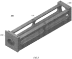
- Fig. 2 , Fig. 3 , and Fig. 4 schematically show examples of the rotary connector 100 according to the present embodiment.
- Fig. 5 schematically shows an example of a structure of the rotary connector 100.
- the rotary connector 100 includes a case 200; and a rotor 300 of a cylindrical shape which is arranged in the case 200 to be able to be rotated with respect to the case 200.
- the rotor 300 has a plurality of conductive ring portions 340 which respectively correspond to a plurality of channels, and a plurality of channel barriers 390 arranged respectively between the plurality of conductive ring portions 340.
- a conductive ring portion 340 includes a core wire ring 350, a GND ring 360, a GND ring 370, a core wire barrier 352 arranged between the core wire ring 350 and the GND ring 360, and a core wire barrier 354 arranged between the core wire ring 350 and the GND ring 370.
- the GND ring 360 may be an example of a first GND ring
- the GND ring 370 may be an example of a second GND ring
- the core wire barrier 352 may be an example of a first core wire barrier
- the core wire barrier 354 may be an example of a second core wire barrier.
- the core wire barrier 352, the core wire barrier 354, and the channel barrier 390 have a disk shape. Lengths of the core wire barrier 352, the core wire barrier 354, and the channel barrier 390, along an axial direction in a cylindrical coordinate system based on the rotor 300, are referred to as thicknesses of the core wire barrier 352, the core wire barrier 354, and the channel barrier 390; and lengths in a radial direction in the cylindrical coordinate system are referred to as diameters of the core wire barrier 352, the core wire barrier 354, and the channel barrier 390.
- the case 200 has an upper surface side portion 210 which corresponds to an upper surface 310 of the rotor 300; a lower surface side portion 220 which corresponds to a lower surface 320 of the rotor 300; and a side surface side portion 230 which covers the rotor 300.
- the case 200 includes a plurality of connector portions 240 which respectively correspond to the plurality of channels.
- a connector portion 240 includes a connector 242, a core wire brush 250, a GND brush 260, and a GND brush 270.
- the connector 242 may be, for example, a so-called SMA (Sub Miniature Type A) connector.
- the core wire brush 250 has one end side connected to the connector 242 and another end side in contact with the core wire ring 350.
- the GND brush 260 has one end side connected to the connector 242 and another end side in contact with the GND ring 360.
- the GND brush 260 may be an example of a first GND brush.
- the GND brush 270 has one end side connected to the connector 242 and another end side in contact with the GND ring 370.
- the GND brush 270 may be an example of a second GND brush.
- the case 200 is constituted by, for example, aluminum.
- the case 200 may be constituted by another metal such as stainless steel.
- the core wire barrier 352 and the core wire barrier 354 are constituted by an insulator.
- the characteristic impedance of each channel depends on the degree of the insulation of the core wire barrier 352 and the core wire barrier 354.
- the thickness of the core wire barrier 352 may be a thickness based on the characteristic impedance of the corresponding channel. That is, the core wire barrier 352 may have a thickness with a degree of the insulation for being able to realize the characteristic impedance of the channel that is set as a target.
- the thickness of the core wire barrier 354 may be a thickness based on the characteristic impedance of the corresponding channel. That is, the core wire barrier 354 may have a thickness with a degree of the insulation for being able to realize the characteristic impedance of the channel that is set as a target.
- Fig. 6 is an illustration for describing a characteristic of the rotary connector 100.
- a certain distance or more is required, so that a gap exists.
- the inventor has discovered that when a high voltage is applied to the core wire brush 250, the core wire brush 250 functions as an antenna, and a leakage radio wave occurs.
- the leakage radio wave may adversely affect an adjacent channel, and thus it is desirable to adopt a configuration that reduces the influence of the leakage radio wave.
- Fig. 7 schematically shows an example of the rotary connector 100.
- the core wire barrier 352 and the core wire barrier 354 in the rotary connector 100 may have shapes in which the leakage radio wave, from the core wire brush 250 in contact with the core wire ring 350 between the core wire barrier 352 and the core wire barrier 354, is hindered from reaching another channel.
- the core wire barrier 352 has a shape in which a diameter on a core wire ring 350 side is greater than a diameter on a GND ring 360 side; and the core wire barrier 354 has a shape in which a diameter on the core wire ring 350 side is greater than a diameter on a GND ring 370 side.
- the core wire barrier 352 and the core wire barrier 354 have a wheel shape of a train. That is, each of the core wire barrier 352 and core wire barrier 354 is constituted by a portion of a disk shape having a first diameter and a portion of a disk shape having a second diameter greater than the first diameter.
- the core wire barrier 352 may be configured to have a shape in which the diameter on the GND ring 360 side is greater than the diameter on the core wire ring 350 side; and the core wire barrier 354 may be configured to have a shape in which the diameter on the GND ring 370 side is greater than the diameter on the core wire ring 350 side.
- Fig. 8 schematically shows an example of the rotary connector 100.
- the core wire barrier 352 has a circular truncated cone shape in which a diameter on the core wire ring 350 side is greater than a diameter on the GND ring 360 side; and the core wire barrier 354 has a circular truncated cone shape in which a diameter on the core wire ring 350 side is greater than a diameter on the GND ring 370 side.
- the shape shown in Fig. 8 as well, it is possible to exhibit the effect of reducing the leakage radio wave by the core wire ring 350 while maintaining the characteristic impedance.
- Fig. 9 schematically shows an example of the rotary connector 100.
- Fig. 7 and Fig. 8 show the examples in which while the thicknesses of the core wire barrier 352 and the core wire barrier 354 are maintained, the diameter of a part is increased; however, the present invention is not limited thereto.
- the core wire barrier 352 and the core wire barrier 354 may be configured to have thicknesses and diameters by which the leakage radio wave of the core wire ring 350 is hindered from reaching another channel, while the characteristic impedance that is set as a target is realized.
- Such a thickness and such a diameter are able to be specified, for example, by checking the characteristic impedance while gradually changing the thickness and the diameter for each rotary connector 100.
- Fig. 10 schematically shows an example of the case 200.
- the plurality of connector portions 240 are arranged side by side on the side surface side portion 230 of the case 200.
- the side surface side portion 230 of the case 200 shown in Fig. 10 includes a plurality of protrusion portions 232 which correspond to the plurality of connector portions 240, respectively.
- Each of the plurality of protrusion portions 232 includes at least one corner portion.
- Fig. 10 shows a case where the plurality of protrusion portions 232 have a rectangular parallelepiped shape.
- the inventor has discovered through the experiment that by arranging the protrusion portion 232 having at least one corner portion near the core wire brush 250, the leakage radio wave of the core wire brush 250 is absorbed by the corner portion.
- the protrusion portion 232 By arranging the protrusion portion 232 at a corresponding position for each of the plurality of connector portions 240, it is possible to reduce the influence of the leakage radio wave of the core wire brush 250.
- Fig. 10 shows an example of 14 protrusion portions 232 when there are 14 channels and 14 connector portions 240 are arranged in two rows in a staggered manner.
- the plurality of protrusion portions 232 may be arranged at positions that respectively correspond to the plurality of connector portions 240, in accordance with the number and the arrangement of the connector portions 240.
- the protrusion portion 232 may have a plurality of corner portions on a side surface.
- a side surface side of the protrusion portion 232 may have a jagged shape.
- Fig. 11 schematically shows an example of the structure of the rotary connector 100.
- the case 200 of the rotary connector 100 shown in Fig. 11 has a plurality of metal partition wall portions 234 which are fixed to the side surface side portion 230, and each of which separates the conductive ring portions 340 that are adjacent to each other.
- the metal partition wall portion 234 has a hole portion 236 in which the rotor 300 is positioned. The rotor 300 rotates in the hole portion 236.
- the metal partition wall portion 234 has a size for hindering the leakage radio wave, from the core wire brushes 250 in contact with the core wire rings 350 of the two conductive ring portions 340 that are adjacent to each other, from reaching each other.
- the material of the upper surface side portion 210, the lower surface side portion 220, the side surface side portion 230, and the connector portion 240 may be aluminum.
- the material of the upper surface side portion 210, the lower surface side portion 220, the side surface side portion 230, and the connector portion 240 may be another metal such as stainless steel.
- the metal partition wall portion 234 may be installed in a manner of being fixed to the side surface side portion 230.
- the metal partition wall portion 234 may be formed integrally with the side surface side portion 230.
- the channel barrier 390 has a greater diameter in comparison with that of the channel barrier 390 shown in Fig. 5 . In this manner, by the channel barrier 390, it is possible to hinder the leakage radio wave of the core wire ring 350 from reaching the adjacent channel.
- the channel barrier 390 may be a solid GND substrate. This can make it easy to block or absorb the leakage radio wave. In addition, it is possible to reduce a weight in comparison with a case where the channel barrier 390 is constituted by a metal such as aluminum.
- the rotor 300 which supports the plurality of channels tends to have a long overall length; however, by setting the channel barrier 390 to be light, it is possible to prevent the rotor 300 from bending.
- 100 rotary connector; 200: case; 210: upper surface side portion; 220: lower surface side portion; 230: side surface side portion; 232 protrusion portion; 234 metal partition wall portion; 236 hole portion; 240: connector portion; 242 connector; 250: core wire brush; 260: GND brush; 270: GND brush; 300: rotor; 310: upper surface; 320: lower surface; 340: conductive ring portion; 350: core wire ring; 352 core wire barrier; 354 core wire barrier; 360: GND ring; 370: GND ring; 390: channel barrier.
Landscapes
- Motor Or Generator Current Collectors (AREA)
- Details Of Connecting Devices For Male And Female Coupling (AREA)
Abstract
Description
- The present invention relates to a rotary connector.
-
Patent Document 1 describes a rotary connector device using a conductive ring and a conductive brush. - Patent Document 1:
Japanese Patent Application Publication No. 2013-143183 - In an embodiment of the present invention, there is provided a rotary connector. The rotary connector may include a case; and a rotor of a cylindrical shape which is arranged in the case to be able to be rotated with respect to the case. The rotor may have a plurality of conductive ring portions which respectively correspond to a plurality of channels. The rotor may have a plurality of channel barriers arranged respectively between the plurality of conductive ring portions. Each of the plurality of conductive ring portions may include a core wire ring. Each of the plurality of conductive ring portions may include a first GND ring. Each of the plurality of conductive ring portions may include a second GND ring. Each of the plurality of conductive ring portions may include a first core wire barrier which is arranged between the core wire ring and the first GND ring. Each of the plurality of conductive ring portions may include a second core wire barrier which is arranged between the core wire ring and the second GND ring. The case may have a plurality of connector portions which respectively correspond to the plurality of channels. Each of the plurality of connector portions may include a connector. Each of the plurality of connector portions may include a core wire brush having one end side connected to the connector and another end side in contact with the core wire ring. Each of the plurality of connector portions may include a first GND brush having one end side connected to the connector and another end side in contact with the first GND ring. Each of the plurality of connector portions may include a second GND brush having one end side connected to the connector and another end side in contact with the second GND ring. The first core wire barrier and the second core wire barrier may have shapes in which a leakage radio wave, from the core wire brush in contact with the core wire ring between the first core wire barrier and the second core wire barrier, is hindered from reaching another channel.
- In the rotary connector, the first core wire barrier may have a shape in which a diameter on a core wire brush side is greater than a diameter on a first GND ring side. The second core wire barrier may have a shape in which a diameter on the core wire brush side is greater than a diameter on a second GND ring side. In the first core wire barrier, a thickness along an axial direction in a cylindrical coordinate system based on the rotor, may be a thickness based on characteristic impedance of the corresponding channel; and in the second core wire barrier, a thickness along an axial direction in a cylindrical coordinate system based on the rotor, may be a thickness based on characteristic impedance of the corresponding channel. The first core wire barrier may have a shape in which a diameter on the first GND ring side is greater than a diameter on the core wire brush side; and the second core wire barrier may have a shape in which a diameter on the second GND ring side is greater than a diameter on the core wire brush side. The rotary connector may further include a plurality of channel barriers which are arranged respectively between the plurality of conductive ring portions, and which are solid GND substrates.
- In any of the rotary connectors described above, the case may have an upper surface side portion which corresponds to an upper surface of the rotor, a lower surface side portion which corresponds to a lower surface of the rotor, and a side surface side portion which covers the rotor; the plurality of connector portions may be arranged side by side on the side surface side portion; the side surface side portion may include a plurality of protrusion portions which correspond to the plurality of connector portions, respectively; and each of the plurality of protrusion portions may include at least one corner portion. The plurality of protrusion portions may have a rectangular parallelepiped shape.
- In any of the rotary connectors described above, the case may have an upper surface side portion which corresponds to an upper surface of the rotor, a lower surface side portion which corresponds to a lower surface of the rotor, a side surface side portion which covers the rotor, and a plurality of metal partition wall portions which are fixed to the side surface side portion, and each of which separates the conductive ring portions that are adjacent to each other; and the plurality of metal partition wall portions may include hole portions in which the rotor is positioned. Each of the plurality of metal partition wall portions may have a size for hindering the leakage radio wave, from the core wire brushes in contact with the core wire rings of the two conductive ring portions that are adjacent to each other, from reaching each other. A material of the upper surface side portion, the lower surface side portion, the side surface side portion, and the plurality of metal partition wall portions may be aluminum. The plurality of metal partition wall portions may be fixed to the side surface side portion, each of which may separate the conductive ring portions that are adjacent to each other, and may be formed integrally with the side surface side portion.
- In an embodiment of the present invention, there is provided a rotary connector. The rotary connector may include a case; and a rotor of a cylindrical shape which is arranged to be able to be rotated with respect to the case. The rotor may have a plurality of conductive ring portions which respectively correspond to a plurality of channels. The rotor may have a plurality of channel barriers arranged respectively between the plurality of conductive ring portions. Each of the plurality of conductive ring portions may include a core wire ring. Each of the plurality of conductive ring portions may include a first GND ring. Each of the plurality of conductive ring portions may include a second GND ring. Each of the plurality of conductive ring portions may include a first core wire barrier which is arranged between the core wire ring and the first GND ring. Each of the plurality of conductive ring portions may include a second core wire barrier which is arranged between the core wire ring and the second GND ring. The case may have a plurality of connector portions which respectively correspond to the plurality of channels. Each of the plurality of connector portions may include a connector. Each of the plurality of connector portions may include a core wire brush having one end side connected to the connector and another end side in contact with the core wire ring. Each of the plurality of connector portions may include a first GND brush having one end side connected to the connector and another end side in contact with the first GND ring. Each of the plurality of connector portions may include a second GND brush having one end side connected to the connector and another end side in contact with the second GND ring. The case may have an upper surface side portion which corresponds to an upper surface of the rotor. The case may have a lower surface side portion which corresponds to a lower surface of the rotor. The case may have a side surface side portion which covers the rotor. The plurality of connector portions may be arranged side by side on the side surface side portion. The side surface side portion may include a plurality of protrusion portions which correspond to the plurality of connector portions, respectively. Each of the plurality of protrusion portions may include at least one corner portion.
- In an embodiment of the present invention, there is provided a rotary connector. The rotary connector may include a case; and a rotor of a cylindrical shape which is arranged to be able to be rotated with respect to the case. The rotor may have a plurality of conductive ring portions which respectively correspond to a plurality of channels. The rotor may have a plurality of channel barriers arranged respectively between the plurality of conductive ring portions. Each of the plurality of conductive ring portions may include a core wire ring. Each of the plurality of conductive ring portions may include a first GND ring. Each of the plurality of conductive ring portions may include a second GND ring. Each of the plurality of conductive ring portions may include a first core wire barrier which is arranged between the core wire ring and the first GND ring. Each of the plurality of conductive ring portions may include a second core wire barrier which is arranged between the core wire ring and the second GND ring. The case may have a plurality of connector portions which respectively correspond to the plurality of channels. Each of the plurality of connector portions may include a connector. Each of the plurality of connector portions may include a core wire brush having one end side connected to the connector and another end side in contact with the core wire ring. Each of the plurality of connector portions may include a first GND brush having one end side connected to the connector and another end side in contact with the first GND ring. Each of the plurality of connector portions may include a second GND brush having one end side connected to the connector and another end side in contact with the second GND ring. The case may have an upper surface side portion which corresponds to an upper surface of the rotor. The case may have a lower surface side portion which corresponds to a lower surface of the rotor. The case may have a side surface side portion which covers the rotor. The case may have a plurality of metal partition wall portions which are fixed to the side surface side portion, and each of which separates the conductive ring portions that are adjacent to each other. The plurality of metal partition wall portions may include hole portions in which the rotor is positioned.
- It should be noted that the summary clause does not necessarily describe all necessary features of the embodiments of the present invention. The present invention may also be a sub-combination of the features described above.
-
-
Fig. 1 is an illustration for describing a characteristic of a rotary connector. -
Fig. 2 schematically shows an example of arotary connector 100. -
Fig. 3 schematically shows an example of therotary connector 100. -
Fig. 4 schematically shows an example of therotary connector 100. -
Fig. 5 schematically shows an example of a structure of therotary connector 100. -
Fig. 6 is an illustration for describing a characteristic of therotary connector 100. -
Fig. 7 schematically shows an example of the structure of therotary connector 100. -
Fig. 8 schematically shows an example of the structure of therotary connector 100. -
Fig. 9 schematically shows an example of the structure of therotary connector 100. -
Fig. 10 schematically shows an example of acase 200. -
Fig. 11 schematically shows an example of the structure of therotary connector 100. -
Fig. 12 shows an example of a metalpartition wall portion 234. - When equipment that involves a cable connection, is rotated, a rotary connector (slip ring) is required. For a multi-pole rotary connector, due to its principle, it is difficult to transmit a wave of an alternating current. It becomes more difficult at a higher frequency and with more cables. In order to create a rotary connector which meets these requirements, it is important to control a resistance between internal poles and match characteristic impedance to a target. A
rotary connector 100 according to the present embodiment contributes to solving such a problem by, for example, carefully considering a barrier shape. In addition, therotary connector 100 contributes to solving such a problem by, for example, carefully considering a casing shape. - Hereinafter, the present invention will be described through embodiments of the invention, but the following embodiments do not limit the invention according to the claims. In addition, not all of the combinations of features described in the embodiments are essential to the solution of the invention.
-
Fig. 1 is an illustration for describing a characteristic of a rotary connector.Fig. 1 shows examples of a cross sectional shape of a rotary connector, an input waveform to the rotary connector, and an output waveform from the rotary connector. - As shown in an upper part of
Fig. 1 , when a distance from an internal contact point to an external contact point A is equal to a distance from the internal contact point to an external contact B, branching occurs on a link, and then coupling to a normal state occurs, thereby causing no signal attenuation to occur. On the other hand, as shown in a lower part ofFig. 1 , when a distance from an internal contact point to an external contact point B is different from a distance from the internal contact point to an external contact B, a phase shift occurs due to a difference in distance, and coupling occurs with the phase shift as is, thereby causing a signal attenuation to occur. - In this way, a path length of the rotary connector varies with a rotation thereof, to adversely affect a high frequency signal. For example, in a case of an RF (Radio Frequency) rotary connector, due to the influence, there is a physical limitation by the frequency. Further, in the RF rotary connector, when the number of channels is increased, a cross section for the cables to pass through is increased, and it becomes unable to handle the high frequency causing a high attenuation. Such a problem is difficult to physically solve, and requires a careful consideration to reduce a reflection and a leakage in another part.
-
Fig. 2 ,Fig. 3 , andFig. 4 schematically show examples of therotary connector 100 according to the present embodiment.Fig. 5 schematically shows an example of a structure of therotary connector 100. Therotary connector 100 includes acase 200; and arotor 300 of a cylindrical shape which is arranged in thecase 200 to be able to be rotated with respect to thecase 200. - The
rotor 300 has a plurality ofconductive ring portions 340 which respectively correspond to a plurality of channels, and a plurality ofchannel barriers 390 arranged respectively between the plurality ofconductive ring portions 340. Aconductive ring portion 340 includes acore wire ring 350, aGND ring 360, aGND ring 370, acore wire barrier 352 arranged between thecore wire ring 350 and theGND ring 360, and acore wire barrier 354 arranged between thecore wire ring 350 and theGND ring 370. TheGND ring 360 may be an example of a first GND ring, theGND ring 370 may be an example of a second GND ring, thecore wire barrier 352 may be an example of a first core wire barrier, and thecore wire barrier 354 may be an example of a second core wire barrier. - The
core wire barrier 352, thecore wire barrier 354, and thechannel barrier 390 have a disk shape. Lengths of thecore wire barrier 352, thecore wire barrier 354, and thechannel barrier 390, along an axial direction in a cylindrical coordinate system based on therotor 300, are referred to as thicknesses of thecore wire barrier 352, thecore wire barrier 354, and thechannel barrier 390; and lengths in a radial direction in the cylindrical coordinate system are referred to as diameters of thecore wire barrier 352, thecore wire barrier 354, and thechannel barrier 390. - The
case 200 has an uppersurface side portion 210 which corresponds to anupper surface 310 of therotor 300; a lowersurface side portion 220 which corresponds to alower surface 320 of therotor 300; and a sidesurface side portion 230 which covers therotor 300. - The
case 200 includes a plurality ofconnector portions 240 which respectively correspond to the plurality of channels. Aconnector portion 240 includes aconnector 242, acore wire brush 250, aGND brush 260, and aGND brush 270. Theconnector 242 may be, for example, a so-called SMA (Sub Miniature Type A) connector. Thecore wire brush 250 has one end side connected to theconnector 242 and another end side in contact with thecore wire ring 350. TheGND brush 260 has one end side connected to theconnector 242 and another end side in contact with theGND ring 360. TheGND brush 260 may be an example of a first GND brush. TheGND brush 270 has one end side connected to theconnector 242 and another end side in contact with theGND ring 370. TheGND brush 270 may be an example of a second GND brush. - The
case 200 is constituted by, for example, aluminum. Thecase 200 may be constituted by another metal such as stainless steel. - The
core wire barrier 352 and thecore wire barrier 354 are constituted by an insulator. The characteristic impedance of each channel depends on the degree of the insulation of thecore wire barrier 352 and thecore wire barrier 354. - The thickness of the
core wire barrier 352 may be a thickness based on the characteristic impedance of the corresponding channel. That is, thecore wire barrier 352 may have a thickness with a degree of the insulation for being able to realize the characteristic impedance of the channel that is set as a target. - The thickness of the
core wire barrier 354 may be a thickness based on the characteristic impedance of the corresponding channel. That is, thecore wire barrier 354 may have a thickness with a degree of the insulation for being able to realize the characteristic impedance of the channel that is set as a target. -
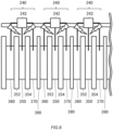
Fig. 6 is an illustration for describing a characteristic of therotary connector 100. In relationships in which thecore wire brush 250, theGND brush 260, and theGND brush 270 come into contact with thecore wire ring 350, theGND ring 360, and theGND ring 370 in a tilted state, between a part of thecase 200 where theconnector 242 is arranged, and therotor 300, a certain distance or more is required, so that a gap exists. - By using the
rotary connector 100 to conduct an experiment, the inventor has discovered that when a high voltage is applied to thecore wire brush 250, thecore wire brush 250 functions as an antenna, and a leakage radio wave occurs. The leakage radio wave may adversely affect an adjacent channel, and thus it is desirable to adopt a configuration that reduces the influence of the leakage radio wave. -
Fig. 7 schematically shows an example of therotary connector 100. Thecore wire barrier 352 and thecore wire barrier 354 in therotary connector 100 may have shapes in which the leakage radio wave, from thecore wire brush 250 in contact with thecore wire ring 350 between thecore wire barrier 352 and thecore wire barrier 354, is hindered from reaching another channel. - As an example, in the
rotary connector 100 shown inFig. 7 , thecore wire barrier 352 has a shape in which a diameter on acore wire ring 350 side is greater than a diameter on aGND ring 360 side; and thecore wire barrier 354 has a shape in which a diameter on thecore wire ring 350 side is greater than a diameter on aGND ring 370 side. In the example shown inFig. 7 , thecore wire barrier 352 and thecore wire barrier 354 have a wheel shape of a train. That is, each of thecore wire barrier 352 andcore wire barrier 354 is constituted by a portion of a disk shape having a first diameter and a portion of a disk shape having a second diameter greater than the first diameter. By increasing only the diameter on thecore wire ring 350 side while maintaining the thickness of thecore wire barrier 352 and thecore wire barrier 354, it is possible to exhibit the effect of reducing the leakage radio wave by thecore wire ring 350 while maintaining the characteristic impedance. - It should be noted that the
core wire barrier 352 may be configured to have a shape in which the diameter on theGND ring 360 side is greater than the diameter on thecore wire ring 350 side; and thecore wire barrier 354 may be configured to have a shape in which the diameter on theGND ring 370 side is greater than the diameter on thecore wire ring 350 side. -
Fig. 8 schematically shows an example of therotary connector 100. Here, differences fromFig. 7 will be mainly described. In an example shown inFig. 8 , thecore wire barrier 352 has a circular truncated cone shape in which a diameter on thecore wire ring 350 side is greater than a diameter on theGND ring 360 side; and thecore wire barrier 354 has a circular truncated cone shape in which a diameter on thecore wire ring 350 side is greater than a diameter on theGND ring 370 side. With the shape shown inFig. 8 as well, it is possible to exhibit the effect of reducing the leakage radio wave by thecore wire ring 350 while maintaining the characteristic impedance. -
Fig. 9 schematically shows an example of therotary connector 100.Fig. 7 andFig. 8 show the examples in which while the thicknesses of thecore wire barrier 352 and thecore wire barrier 354 are maintained, the diameter of a part is increased; however, the present invention is not limited thereto. Thecore wire barrier 352 and thecore wire barrier 354 may be configured to have thicknesses and diameters by which the leakage radio wave of thecore wire ring 350 is hindered from reaching another channel, while the characteristic impedance that is set as a target is realized. Such a thickness and such a diameter are able to be specified, for example, by checking the characteristic impedance while gradually changing the thickness and the diameter for eachrotary connector 100. -
Fig. 10 schematically shows an example of thecase 200. The plurality ofconnector portions 240 are arranged side by side on the sidesurface side portion 230 of thecase 200. The sidesurface side portion 230 of thecase 200 shown inFig. 10 includes a plurality ofprotrusion portions 232 which correspond to the plurality ofconnector portions 240, respectively. Each of the plurality ofprotrusion portions 232 includes at least one corner portion.Fig. 10 shows a case where the plurality ofprotrusion portions 232 have a rectangular parallelepiped shape. - The inventor has discovered through the experiment that by arranging the
protrusion portion 232 having at least one corner portion near thecore wire brush 250, the leakage radio wave of thecore wire brush 250 is absorbed by the corner portion. By arranging theprotrusion portion 232 at a corresponding position for each of the plurality ofconnector portions 240, it is possible to reduce the influence of the leakage radio wave of thecore wire brush 250. -
Fig. 10 shows an example of 14protrusion portions 232 when there are 14 channels and 14connector portions 240 are arranged in two rows in a staggered manner. The plurality ofprotrusion portions 232 may be arranged at positions that respectively correspond to the plurality ofconnector portions 240, in accordance with the number and the arrangement of theconnector portions 240. - It should be noted that the
protrusion portion 232 may have a plurality of corner portions on a side surface. For example, a side surface side of theprotrusion portion 232 may have a jagged shape. By increasing the number of corner portions, it is possible to enhance the ability of thecore wire brush 250 to absorb the leakage radio wave. -
Fig. 11 schematically shows an example of the structure of therotary connector 100. Thecase 200 of therotary connector 100 shown inFig. 11 has a plurality of metalpartition wall portions 234 which are fixed to the sidesurface side portion 230, and each of which separates theconductive ring portions 340 that are adjacent to each other. As shown inFig. 12 , the metalpartition wall portion 234 has ahole portion 236 in which therotor 300 is positioned. Therotor 300 rotates in thehole portion 236. - The metal
partition wall portion 234 has a size for hindering the leakage radio wave, from thecore wire brushes 250 in contact with the core wire rings 350 of the twoconductive ring portions 340 that are adjacent to each other, from reaching each other. - The material of the upper
surface side portion 210, the lowersurface side portion 220, the sidesurface side portion 230, and theconnector portion 240 may be aluminum. The material of the uppersurface side portion 210, the lowersurface side portion 220, the sidesurface side portion 230, and theconnector portion 240 may be another metal such as stainless steel. The metalpartition wall portion 234 may be installed in a manner of being fixed to the sidesurface side portion 230. The metalpartition wall portion 234 may be formed integrally with the sidesurface side portion 230. - By the
case 200 having the plurality of metalpartition wall portions 234, it is possible to reduce the leakage influence of the leakage radio wave of thecore wire ring 350 between the plurality of channels. - In the example shown in
Fig. 11 , thechannel barrier 390 has a greater diameter in comparison with that of thechannel barrier 390 shown inFig. 5 . In this manner, by thechannel barrier 390, it is possible to hinder the leakage radio wave of thecore wire ring 350 from reaching the adjacent channel. - The
channel barrier 390 may be a solid GND substrate. This can make it easy to block or absorb the leakage radio wave. In addition, it is possible to reduce a weight in comparison with a case where thechannel barrier 390 is constituted by a metal such as aluminum. Therotor 300 which supports the plurality of channels tends to have a long overall length; however, by setting thechannel barrier 390 to be light, it is possible to prevent therotor 300 from bending. - While the present invention has been described by way of the embodiments, the technical scope of the present invention is not limited to the above-described embodiments. It is apparent to persons skilled in the art that various alterations or improvements can be added to the above-described embodiments. It is also apparent from the scope of the claims that the embodiments added with such alterations or improvements can be included in the technical scope of the invention.
- The operations, procedures, steps, and stages of each process executed by a device, system, program, and method shown in the claims, embodiments, or diagrams can be achieved in any order as long as the order is not indicated by "prior to," "before," or the like and as long as the output from a previous process is not used in a later process. Even if the process flow is described using phrases such as "first" or "next" in the claims, embodiments, or diagrams, it does not necessarily mean that the process must be executed in this order.
- 100: rotary connector; 200: case; 210: upper surface side portion; 220: lower surface side portion; 230: side surface side portion; 232 protrusion portion; 234 metal partition wall portion; 236 hole portion; 240: connector portion; 242 connector; 250: core wire brush; 260: GND brush; 270: GND brush; 300: rotor; 310: upper surface; 320: lower surface; 340: conductive ring portion; 350: core wire ring; 352 core wire barrier; 354 core wire barrier; 360: GND ring; 370: GND ring; 390: channel barrier.
Claims (4)
- A rotary connector comprising:a case; anda rotor of a cylindrical shape which is arranged in the case to be able to be rotated with respect to the case, whereinthe rotor hasa plurality of conductive ring portions which respectively correspond to a plurality of channels, anda plurality of channel barriers arranged respectively between the plurality of conductive ring portions,each of the plurality of conductive ring portions includesa core wire ring, wherein the core wire ring includes a plurality of core wire rings,a first GND ring,a second GND ring,a first core wire barrier arranged between the core wire ring and the first GND ring, anda second core wire barrier arranged between the core wire ring and the second GND ring,the case has a plurality of connector portions which respectively correspond to the plurality of channels,each of the plurality of connector portions includesa connector,a core wire brush having one end side connected to the connector and another end side in contact with the core wire ring, wherein the core wire brush includes a plurality of core wire brushes,a first GND brush having one end side connected to the connector and another end side in contact with the first GND ring, anda second GND brush having one end side connected to the connector and another end side in contact with the second GND ring,the first core wire barrier and the second core wire barrier have shapes in which a leakage radio wave, from the core wire brush in contact with the core wire ring between the first core wire barrier and the second core wire barrier, is hindered from reaching another channel,the first core wire barrier has a shape in which a diameter on a core wire brush side is greater than a diameter on a first GND ring side, andthe second core wire barrier has a shape in which a diameter on the core wire brush side is greater than a diameter on a second GND ring side.
- The rotary connector according to claim 1, whereinthe case hasan upper surface side portion which corresponds to an upper surface of the rotor,a lower surface side portion which corresponds to a lower surface of the rotor,a side surface side portion which covers the rotor, anda plurality of metal partition wall portions which are fixed to the side surface side portion, and each of which separates the conductive ring portions that are adjacent to each other, andthe plurality of metal partition wall portions include hole portions in which the rotor is positioned.
- The rotary connector according to claim 2, wherein each of the plurality of metal partition wall portions has a size for hindering the leakage radio wave, from the core wire brushes in contact with the core wire rings of the two conductive ring portions that are adjacent to each other, from reaching each other.
- The rotary connector according to claim 2, wherein a material of the upper surface side portion, the lower surface side portion, the side surface side portion, and the plurality of metal partition wall portions is aluminum.
Applications Claiming Priority (2)
| Application Number | Priority Date | Filing Date | Title |
|---|---|---|---|
| JP2022208313A JP7271780B1 (en) | 2022-12-26 | 2022-12-26 | rotating connector |
| PCT/JP2023/046598 WO2024143342A1 (en) | 2022-12-26 | 2023-12-26 | Rotary connector |
Publications (2)
| Publication Number | Publication Date |
|---|---|
| EP4572036A1 true EP4572036A1 (en) | 2025-06-18 |
| EP4572036A4 EP4572036A4 (en) | 2025-12-24 |
Family
ID=86382669
Family Applications (1)
| Application Number | Title | Priority Date | Filing Date |
|---|---|---|---|
| EP23912121.3A Pending EP4572036A4 (en) | 2022-12-26 | 2023-12-26 | ROTARY CONNECTOR |
Country Status (4)
| Country | Link |
|---|---|
| US (1) | US12470030B2 (en) |
| EP (1) | EP4572036A4 (en) |
| JP (1) | JP7271780B1 (en) |
| WO (1) | WO2024143342A1 (en) |
Family Cites Families (12)
| Publication number | Priority date | Publication date | Assignee | Title |
|---|---|---|---|---|
| JP2001210430A (en) | 2000-01-27 | 2001-08-03 | Matsushita Electric Ind Co Ltd | High frequency signal connector |
| JP4237192B2 (en) | 2006-03-29 | 2009-03-11 | 日本電産サーボ株式会社 | Slip ring with connecting terminal using sliding ring |
| JP4940468B2 (en) | 2006-11-20 | 2012-05-30 | 多摩川精機株式会社 | Slip ring |
| JP4379821B2 (en) | 2007-03-29 | 2009-12-09 | 日本航空電子工業株式会社 | Manufacturing method of differential transmission contact |
| US7559767B2 (en) * | 2007-05-15 | 2009-07-14 | Moog Inc. | High-frequency drum-style slip-ring modules |
| TWM331247U (en) * | 2007-10-05 | 2008-04-21 | Taiwan Long Hawn Entpr Co | Assembly slip ring |
| JP2012099376A (en) * | 2010-11-04 | 2012-05-24 | Nidec Servo Corp | Slip ring device |
| CN202340044U (en) | 2011-12-09 | 2012-07-18 | 杭州驰宏科技有限公司 | Multifunctional slip ring |
| JP5809987B2 (en) | 2012-01-06 | 2015-11-11 | 日本電産サンキョー株式会社 | Rotating connector device |
| KR101285280B1 (en) * | 2013-02-18 | 2013-07-15 | 권성미 | Anti-twist rotator bearing with connector |
| JP6253558B2 (en) | 2014-09-25 | 2017-12-27 | 株式会社東芝 | Slip ring device |
| CN113629466B (en) * | 2021-08-10 | 2024-09-03 | 向雨 | Electric slip ring |
-
2022
- 2022-12-26 JP JP2022208313A patent/JP7271780B1/en active Active
-
2023
- 2023-12-26 EP EP23912121.3A patent/EP4572036A4/en active Pending
- 2023-12-26 WO PCT/JP2023/046598 patent/WO2024143342A1/en not_active Ceased
-
2025
- 2025-03-21 US US19/086,175 patent/US12470030B2/en active Active
Also Published As
| Publication number | Publication date |
|---|---|
| US20250219341A1 (en) | 2025-07-03 |
| EP4572036A4 (en) | 2025-12-24 |
| US12470030B2 (en) | 2025-11-11 |
| JP7271780B1 (en) | 2023-05-11 |
| WO2024143342A1 (en) | 2024-07-04 |
| JP2024092410A (en) | 2024-07-08 |
Similar Documents
| Publication | Publication Date | Title |
|---|---|---|
| CN110731033B (en) | Collinear antenna structure with independent access | |
| US7834271B2 (en) | Cabling having shielding separators | |
| US8460024B2 (en) | Contact assembly for electrical connector | |
| US7622680B2 (en) | Cable jacket with internal splines | |
| JP5454648B2 (en) | Differential signal cable, transmission cable using the same, and method for manufacturing differential signal cable | |
| US20110253415A1 (en) | Coaxial Cable with Wire Layer | |
| JP2011086458A (en) | Differential signaling cable and transmission cable using the same, and method of manufacturing differential signaling cable | |
| US20170025203A1 (en) | Cable having improved wires arrangement | |
| US20220254549A1 (en) | A composite cable | |
| CN111029864A (en) | Radio frequency coaxial connector and insulating support | |
| US8568166B2 (en) | High-voltage coaxial cable and connector | |
| US12470030B2 (en) | Rotary connector | |
| EP3764457A1 (en) | Waveguide for transmitting electromagnetic wave signals | |
| CN113381245B (en) | Plug connection for connecting a cable to an electrical component | |
| US20110174531A1 (en) | Cable with twisted pairs of insulated conductors | |
| US11108181B2 (en) | Vibration resistant high-power electrical connector | |
| EP2784788A1 (en) | Cable and method of manufacturing a cable | |
| US20200335241A1 (en) | Cable and A Combined Cable | |
| JP5646940B2 (en) | Electromagnetic wave transmission medium | |
| EP3246925A1 (en) | Balanced pair data transmission line | |
| EP3301750A1 (en) | Hollow conductor connecting member, hollow conductor system and method for forming a hollow conductor system | |
| CN103311644A (en) | Accumulated non-contact broadband high-power rotating hinge and achievement method thereof | |
| JP2007110716A (en) | Multiple planar inductor coaxial surge suppressor | |
| CN113488775A (en) | Leaky cable and system | |
| US20250202155A1 (en) | Connector and Power Device Comprising the Same |
Legal Events
| Date | Code | Title | Description |
|---|---|---|---|
| STAA | Information on the status of an ep patent application or granted ep patent |
Free format text: STATUS: THE INTERNATIONAL PUBLICATION HAS BEEN MADE |
|
| PUAI | Public reference made under article 153(3) epc to a published international application that has entered the european phase |
Free format text: ORIGINAL CODE: 0009012 |
|
| STAA | Information on the status of an ep patent application or granted ep patent |
Free format text: STATUS: REQUEST FOR EXAMINATION WAS MADE |
|
| 17P | Request for examination filed |
Effective date: 20250311 |
|
| AK | Designated contracting states |
Kind code of ref document: A1 Designated state(s): AL AT BE BG CH CY CZ DE DK EE ES FI FR GB GR HR HU IE IS IT LI LT LU LV MC ME MK MT NL NO PL PT RO RS SE SI SK SM TR |
|
| REG | Reference to a national code |
Ref country code: DE Ref legal event code: R079 Free format text: PREVIOUS MAIN CLASS: H01R0039000000 Ipc: H01R0039080000 |
|
| A4 | Supplementary search report drawn up and despatched |
Effective date: 20251120 |
|
| RIC1 | Information provided on ipc code assigned before grant |
Ipc: H01R 39/08 20060101AFI20251114BHEP Ipc: H01R 39/64 20060101ALI20251114BHEP Ipc: H01R 107/00 20060101ALN20251114BHEP |
|
| DAV | Request for validation of the european patent (deleted) | ||
| DAX | Request for extension of the european patent (deleted) |