EP4571400A1 - Spectacle lens and spectacles - Google Patents
Spectacle lens and spectacles Download PDFInfo
- Publication number
- EP4571400A1 EP4571400A1 EP23852320.3A EP23852320A EP4571400A1 EP 4571400 A1 EP4571400 A1 EP 4571400A1 EP 23852320 A EP23852320 A EP 23852320A EP 4571400 A1 EP4571400 A1 EP 4571400A1
- Authority
- EP
- European Patent Office
- Prior art keywords
- layer
- lens
- spectacle lens
- cut
- refractive index
- Prior art date
- Legal status (The legal status is an assumption and is not a legal conclusion. Google has not performed a legal analysis and makes no representation as to the accuracy of the status listed.)
- Pending
Links
Images




Classifications
-
- G—PHYSICS
- G02—OPTICS
- G02B—OPTICAL ELEMENTS, SYSTEMS OR APPARATUS
- G02B1/00—Optical elements characterised by the material of which they are made; Optical coatings for optical elements
- G02B1/10—Optical coatings produced by application to, or surface treatment of, optical elements
- G02B1/11—Anti-reflection coatings
-
- G—PHYSICS
- G02—OPTICS
- G02B—OPTICAL ELEMENTS, SYSTEMS OR APPARATUS
- G02B1/00—Optical elements characterised by the material of which they are made; Optical coatings for optical elements
- G02B1/10—Optical coatings produced by application to, or surface treatment of, optical elements
- G02B1/11—Anti-reflection coatings
- G02B1/113—Anti-reflection coatings using inorganic layer materials only
- G02B1/115—Multilayers
-
- G—PHYSICS
- G02—OPTICS
- G02C—SPECTACLES; SUNGLASSES OR GOGGLES INSOFAR AS THEY HAVE THE SAME FEATURES AS SPECTACLES; CONTACT LENSES
- G02C11/00—Non-optical adjuncts; Attachment thereof
- G02C11/02—Ornaments, e.g. exchangeable
-
- G—PHYSICS
- G02—OPTICS
- G02C—SPECTACLES; SUNGLASSES OR GOGGLES INSOFAR AS THEY HAVE THE SAME FEATURES AS SPECTACLES; CONTACT LENSES
- G02C7/00—Optical parts
- G02C7/02—Lenses; Lens systems ; Methods of designing lenses
-
- G—PHYSICS
- G02—OPTICS
- G02C—SPECTACLES; SUNGLASSES OR GOGGLES INSOFAR AS THEY HAVE THE SAME FEATURES AS SPECTACLES; CONTACT LENSES
- G02C7/00—Optical parts
- G02C7/02—Lenses; Lens systems ; Methods of designing lenses
- G02C7/021—Lenses; Lens systems ; Methods of designing lenses with pattern for identification or with cosmetic or therapeutic effects
Definitions
- the present disclosure relates to a spectacle lens and spectacles.
- spectacle frames will also be referred to simply as frames, and rims of such spectacle frames (a member into which a spectacle lens that has been edged is fit), in particular, will be discussed.
- Spectacle lenses that have been edged will also be referred to as cut lenses.
- Edging will also be referred to as being cut to frame.
- the weight of the frame and the weight of decorative material on the spectacles is preferable for the weight of the frame and the weight of decorative material on the spectacles to be reduced as much as possible.
- thin frames and lightweight frames have been developed.
- lightweight frames that have been developed include rimless frames, which have no rim, and half-rim frames, where the rim is on only a portion of the frame (for example, the lower half of the frame).
- a rim has the effect of accentuating the contours of a cut lens and providing a distinctive look to the face of the wearer.
- An objective of the present disclosure is to provide a technique for appropriately accentuating the contours of a cut lens and improving the outer appearance, regardless of whether or not there is a rim.
- a spectacle lens provided with
- the spectacle lens according to the first aspect wherein the material removal area also forms a decorative pattern other than the cut lens-like marking.
- the spectacle lens according to the second aspect wherein the decorative pattern is applied on an end on the inside of the cut lens-like marking.
- the spectacle lens according to any one of the first to third aspects, wherein the cut lens-like marking is ring-shaped.
- the spectacles according to the fifth aspect wherein the material removal area also forms a decorative pattern other than the edge outline.
- the spectacles according to the sixth aspect wherein the decorative pattern is applied on an end on the inside of the edge outline.
- the spectacles according to any one of the fifth to seventh aspects wherein the edge outline is ring-shaped.
- the present disclosure appropriately accentuates the contours of a cut lens and improves the outer appearance, regardless of whether or not there is a rim.
- FIG. 1A is a front view of a spectacle lens according to one embodiment of the present disclosure.
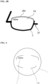
- FIG. 1B is a bottom view of the spectacle lens according to the one embodiment of the present disclosure.
- FIG. 2A is a front view of a spectacle lens according to another embodiment of the present disclosure.
- FIG. 2B is a partial schematic front view of spectacles after the spectacle lens of FIG. 2A is cut and fit into a full-rim frame.
- FIG. 2C is a partial schematic front view of spectacles after the spectacle lens of FIG. 2A is cut and fit into a half-rim frame.
- FIG. 3A is a front view of a spectacle lens according to another embodiment of the present disclosure.
- FIG. 3B is a partial schematic front view of spectacles after the spectacle lens of FIG. 3A is cut and fit into a half-rim frame.
- FIG. 4 is a front view of a spectacle lens according to another embodiment of the present disclosure.
- FIG. 5 is a front view of a spectacle lens according to another embodiment of the present disclosure.
- FIG. 6 is a front view of a spectacle lens according to another embodiment of the present disclosure.
- the description discusses a third person perspective of the spectacles in a worn state as seen from the front.
- the side of the spectacle lens by the optical center will be referred to as the inside, and the side of the spectacle lens by the outermost edge will be referred to as the outside.
- the description provides an example in which the optical center matches the geometric center and centration center.
- the optical center will also be referred to as the lens center.
- the frame center side of a cut lens that has been cut to frame will be referred to as the inside, and the side of the cut lens by the outermost edge will be referred to as the outside.
- the contour of the outermost edge of the cut lens matches the contour of a cut lens shape 5 of a spectacle lens 1 before being cut to frame.
- the frame center is the center position of the cut lens in the spectacles when worn as seen from the front by a third person (that is, the region on the inside of the rim).
- the center position of the cut lens may be the geometric center of a rectangular shape (boxing) that circumscribes and encloses the cut lens.
- the frame center may match the optical center and the centration center.
- the application of the marking 2M in a cut lens-like shape can also constitute a method for manufacturing a spectacle lens according to the present embodiment.
- a marking is formed by partially removing the anti-reflective film.
- This marking 2M has a cut lens-like shape.
- the "cut lens-like” may or may not be the predetermined cut lens shape 5 for a single uncut spectacle lens.
- "cut lens-like” refers to the shape of a spectacle lens in a front view that can be used as a cut lens.
- the cut lens-like shape is mainly formed from arcs (concave toward the lens center) and/or straight lines. If the predetermined cut lens shape is complex, curved lines other than arcs may be used to match the cut lens shape.
- a "cut lens-like marking 2M" excludes icons (logos and brand marks). Numbers such as product numbers, text characters, etc., are also excluded. Note that text characters, numbers, or an icon may be provided on the spectacle lens of the present embodiment as a decorative pattern 3 (to be described later) separate from the marking 2M.
- the cut lens-like marking 2M may be formed along the cut-to-frame outer edge shape of the lens as a band-like region with a specific width in the vicinity of the outer edge. As will be described later, the cut lens-like marking 2M may also be formed along a portion of the cut-to-frame outer edge of the lens. In that case, the cut lens-like marking 2M may be formed as a band-like region having a desired width and length, as will be described later.
- the cut lens-like marking 2M may also be referred to as an "edge outline 2M" of the cut lens shape 5. That is, in the present embodiment, it can also be said that the edge outline 2M is marked on an uncut spectacle lens.
- edge outline 2M Each of the features of the edge outline 2M to be described later also apply to the marking 2M.
- the explanation will primarily focus on the edge outline 2M.
- edge outline 2M in the description, as the name suggests, is a line outlining the contour of the cut lens shape 5, which indicates the planned cutting position.
- the edge outline 2M may have a similar shape to the contour of the cut lens shape 5.
- edge outline 2M may have a similar shape to the contour of the cut lens shape 5 with some added degree of variation such that there is within about a 10% difference in the distance between the contour of the cut lens shape 5 and the edge outline 2M.
- the contour of the cut lens shape 5 indicating the planned cutting position may or may not be marked on the spectacle lens. Marking the edge outline 2M to overlap the contour of the cut lens shape 5 will result in the contour of the cut lens shape 5 being marked on the spectacle lens. For example, if the width of the edge outline 2M in the spectacle lens 1 according to the present embodiment is increased, the edge outline 2M on a spectacle lens 1A after being fit into a frame 2F will stick out from the rim shape ( FIG. 2A, FIG. 2B ). On the other hand, the edge outline 2M may be marked in such a manner as to not contact the cut lens shape 5 (to be more precise, marked so as to be on the inside of and not contacting the cut lens shape 5) ( FIG. 1A, FIG. 1B , FIG. 5, FIG. 6 ).
- the edge outline may be marked at a position that does not overlap the contour of the cut lens shape 5 and is offset to the inside of the contour of the cut lens shape 5.
- edge outline it should not be separated too far from the contour of the cut lens shape 5.
- the distance of separation (shortest distance) from the contour of the cut lens shape 5 to the edge outline is, in increasing preference, 3.0 mm or shorter, 2.0 mm or shorter, or 1.0 mm or shorter.
- the "edge outline 2M" in the description, like the marking 2M, is mainly formed from arcs and/or straight lines.
- the edge outline 2M may be a closed loop (a ring shape) or may be an open loop (where part of the ring-shaped edge outline is removed).
- the open loop can also be said to be the edge outline when only a part thereof is provided.
- the edge outline 2M may be marked only partially on the contour of the cut lens as depicted in FIG. 4 .
- the edge outline 2M when being marked in this manner may, for example, be placed at four locations (four corners) as is shown in FIG. 4 , or also may be placed at other locations.
- the "edge outline 2M” in the description refers to a portion visible to the eye. For example, one such case is when the closed loop forming the edge outline 2M is visible as a dashed line.
- the solid portions of the dashed line are lines of exposed portions of the anti-reflective film which have been exposed in lines by continuously etching dots by laser processing, which will be described later.
- the gaps in the dashed line are where there has been no exposure. Because of the differences in the state of etching, a dashed edge outline 2M can be seen in a front view of the spectacle lens.
- the "edge outline 2M” in the description refers to the line-shaped portions that have actually been etched. Note that when the spectacle lens 1 is fitted into a frame, the edge outline 2M would be visible when observed from the object side of the spectacle lens 1.
- FIG. 7 For example, an explanation will be provided using FIG. 7 .
- FIG. 7 is an explanatory view for explaining a favorable example of the edge outlines based on FIG. 4 .
- the description considers an edge outline 2M to be formed at a fan-shaped region a in the range of rotational angles 15° to 60° when being rotated counter-clockwise from 0°, which is defined as the right side of the horizontal direction as seen from the lens center of an uncut spectacle lens.
- the description considers an edge outline 2M to be formed at a fan-shaped region b in the range of rotational angles 120° to 165°, a fan-shaped region c in the range of rotational angles 195° to 240°, and a fan-shaped region d in the range of rotational angles 300° to 345°.
- Each of fan-shaped regions a to d have a central angle of 45°. The central angles are expressed as a1 to d1.
- edge outline 2M refers to an etched portion continuously connecting the two sides of one fan-shaped region centered at the lens center.
- there are multiple edge outlines 2M (each for one of the fan-shaped regions a to d, for a total of four).
- a closed ring shape can be formed.
- Each edge outline 2M in FIG. 7 can also be said to be a solid line portion of a dashed line.
- a spectacle lens will always have a hidden marking and that the left-right (horizontal) direction, and the up-down (vertical direction) by extension, is identifiable when the lens is fit into a frame.
- the edge outline 2M may be provided in the present embodiment throughout fan-shaped regions having a total central angle of 60° or more (preferably, in increasing order of preference, 90° or more, 120° or more, 150° or more, 180° or more, 210° or more, 240° or more, 270° or more, 300° or more, or 330° or more) in the entire spectacle lens.
- the edge outline 2M may be the solid portion of a dashed line as mentioned earlier, a solid line itself, or the solid line portion (for example, dots in laser processing) in a dotted line. There may be a single line or multiple lines (see FIG. 5 ). If there are multiple lines, the thickness of the lines may be changed. Furthermore, the lines may include different types of lines, like those described above. Furthermore, the edge outline may be provided in a checkerboard pattern (hereinafter referred to as a checker pattern) constituted by the solid portion and gaps of a dashed line alternating in the vertical direction, as shown in FIG. 6 .
- a checker pattern hereinafter referred to as a checker pattern
- the minimum width of the line may be 1.0 mm or greater, for example. There is no limit to the maximum value, but a value of 3.0 mm or less, for example, may be set.
- these features can improve the aesthetic appeal of the spectacle lens 1A after being edged (after being fit into a frame).
- the rim has the effect of accentuating the contours of cut lenses and thereby providing a distinctive look to the face of the wearer.
- the edge outline will function as a so-called imitation rim and accentuate the contour of cut lenses in even rimless spectacles and improve their visual appeal.
- the above features can also be applied in the form of an unobtrusive imitation rim with less of a presence than existing rims.
- the degree of emphasis can be chosen, as appropriate, according to the dimensions (thickness) of the imitation rim.
- the frame may be a rimless or half-rim frame, and the edge outline may be marked as an imitation rim at least at locations where there is no rim ( FIG. 2A , FIG. 3A , FIG. 3B ).
- the edge outline 2M would be present at the time of edging, and it will suffice to discard the spectacle lens only when there is a defect on the inside of the edge outline 2M. As a result, it is possible to use spectacle lenses that would have been discarded in the past.
- the spectacle lens according to the present embodiment has an object-side surface and an eye-side surface as optical surfaces.
- the "object-side surface (object surface)” is the surface on the object side of the spectacle lens when the spectacles that the lens is provided in are worn by a wearer.
- the "eye-side surface (eye surface)” is the opposite, that is, the surface on the eye side of the spectacle lens when the spectacles that the lens is provided in are worn by the wearer.
- the object-side surface is a convex surface and the eye-side surface is a concave surface, that is, a spectacle lens is typically a meniscus lens. This is likewise the case for the spectacle lens after edging (cut lens).
- FIG. 8 is a front view of a processing example of the spectacle lens according to the present embodiment.
- the spectacle lens 1 with a front view circular shape (with an outer diameter of, for example, ⁇ 60-80 mm) is edged (cut to frame) so that the lens outer shape matches a rim shape 2 of a spectacle frame worn by a wearer.
- the edge outline 2M is marked on the spectacle lens before edging.
- the example used in the present embodiment is one in which the decorative pattern 3 representing a logo or brand mark or other icon, text characters, symbol, design, etc., is marked on an optical surface so as to be within the lens region after being cut to frame.
- the "decorative pattern 3" refers to a separate pattern from the edge outline 2M. In the present embodiment, both are created under the same work processes.
- the decorative pattern may be provided at an end of the cut lens shape 5 (for example, at least any one of the four corners) on the inside of the edge outline.
- the decorative pattern 3 will also provide a distinctive look when provided at the end, further improving the visual appeal.
- At least part of the decorative pattern 3 may be present on the outside of the inner circumscribed circle of the cut lens, which would be centered at the frame center (in the case of the spectacle lens before edging, the lens center).
- At least part of the decorative pattern 3 may be present on the inside of the marking 2M and the outside of the inner circumscribed circle of the marking 2M.
- This arrangement is depicted in FIG. 9 .
- FIG. 9 is a view of a specific example, based on FIG. 1A , in which the decorative pattern is provided at an end of the cut lens shape 5 (for example, at least any one of the four corners) on the inside of the edge outline.
- the edge outline 2M and decorative pattern 3 are marked using the processing steps explained below.
- FIG. 10 is a flowchart showing an example of the steps of the method for manufacturing a spectacle lens according to the present embodiment.
- a lens base material serving as an optical base material is prepared, and the lens base material is ground according to prescription information of a spectacle wearer and dyed if necessary (step 101; hereinafter “step” is abbreviated as the letter “S").
- the lens base material a resin material having a refractive index (nD) of about 1.50 to 1.74 is used, for example.
- the resin material include allyl diglycol carbonate, urethane-based resin, polycarbonate, thiourethane-based resin, and episulfide resin.
- the lens base material may be composed of other resin materials that provide a desired degree of refraction or may be composed of inorganic glass.
- the lens base material has an optical surface for forming a specific lens shape on each of the object-side surface and the eye-side surface.
- the specific lens shape may form any of a single focal lens, a multifocal lens, a progressive power lens, etc., and in any of these examples, each optical surface is formed from a curved surface specified based on the prescription information of the spectacle wearer. While these optical surfaces are formed by grinding, for example, the optical surfaces may also be cast (molded) products that do not require grinding.
- lens base material may be ground and dyed using known techniques, and detailed explanations will be omitted here.
- a hard coat film is formed on at least one optical surface of the lens base material, preferably on both optical surfaces (S102).
- the HC film is, for example, a film formed using a curable material containing a silicon compound and has a thickness of about 3 ⁇ m to 4 ⁇ m.
- the refractive index (nD) of the HC film is close to the refractive index of the material of the lens base material described above, for example, about 1.49 to 1.74, and the film structure is selected according to the material of the lens base material. Such an HC film can improve the durability of the spectacle lens.
- the HC film may be formed, for example, by a dipping method using a solution in which a curable material containing a silicon compound is dissolved.
- an anti-reflection film (AR film) is subsequently formed over the HC film (S103).
- the AR film is a film having a multilayer structure in which films with different refractive indexes are layered and prevents reflection of light via interference.
- the AR film has a multilayer structure in which a low refractive index layer and a high refractive index layer are layered.
- the low refractive index layer is composed of silicon dioxide (SiO 2 ) having a refractive index of about 1.43 to 1.47, for example.
- the high refractive index layer is composed of a material having a higher refractive index than the low refractive index layer and is formed using, for example, zirconium oxide (ZrO 2 ), tin oxide (SnO 2 ), niobium oxide (Nb 2 O 5 ), tantalum oxide (Ta 2 O 5 ), titanium oxide (TiO 2 ), yttrium oxide (Y 2 O 3 ), aluminum oxide (Al 2 O 3 ), mixtures thereof (e.g., indium tin oxide (ITO)), etc.
- ZrO 2 zirconium oxide
- a high refractive index layer containing Sn and O has greater reactivity to ultrashort pulse lasers, which will be described later, than other layers, and thus functions as a reactive layer.
- the above SnO 2 layer and ITO layer correspond to this high refractive index layer.
- the "reactive layer” in the description refers to a layer having low excitation energy when irradiated with a laser beam.
- an ultrashort pulse laser is applied.
- An SnO 2 layer which can serve as the reactive layer, has extremely low excitation energy due to multiphoton absorption (for example, two-photon absorption) and is highly reactive. This also applies to an ITO layer, and the ITO layer can also serve as the reactive layer in the description.
- the SnO 2 layer (or ITO layer) sublimes or evaporates and disappears from the irradiation area together with the overlying SiO 2 layer.
- the reactive layer having relatively higher reactivity than the other layers included in the multilayer structure refers to the SnO 2 layer or the ITO layer according to the one example of the disclosure.
- This reactive layer may be set as a reactive layer having the highest reactivity compared to the other layers included in the multilayer structure.
- the topmost layer of the AR film having the multilayer structure is formed as a low refractive index layer (e.g., SiO 2 layer). Forming such an AR film can improve the visibility of the pattern formed by laser processing in the present aspect by the differences in visible light reflectance caused by irradiating with illumination light.
- a low refractive index layer e.g., SiO 2 layer.
- the bottommost layer (on the base material side) of the multilayer structure is also preferably a low refractive index layer (e.g., SiO 2 layer).
- the AR film may be formed using, for example, ion-assisted deposition.
- a water-repellent film may be formed on the low refractive index layer at the topmost layer of the AR film.
- the water-repellent film may also be referred to as an antifouling film.
- the water-repellent film may be formed before or after marking according to the present embodiment.
- the water-repellent film is a film that provides water repellency to a surface and can be formed by applying a fluorine-based compound solution such as metaxylene hexafluoride, for example.
- the water-repellent film may be formed by, for example, ion-assisted vapor deposition, like the AR film.
- another functional layer may be formed on the AR film. Whether or not such a functional layer contains a metal component is not a problem as long as precision etching by laser irradiation is possible. Furthermore, such a functional layer may be a uniform film or may be dispersed on the surface.
- a thin film having a layered structure like that shown in FIG. 11 is formed on the optical surface of the lens base material.
- FIG. 11 is a side cross-sectional view of an example of the layered structure of the thin film according to the present embodiment.
- the layered structure in the illustrated example is formed by an HC film 12, an AR film 13, and a water-repellent film 14 being layered in this order on the optical surface of a lens base material 11.
- the AR film 13 has a multilayer structure formed by layering an SiO 2 layer 13a, which is a low refractive index layer, and an SnO 2 layer 13b and a ZrO 2 layer 13c, which are high refractive index layers, with the topmost layer (i.e., the surface layer on the side of the water-repellent film 14) being the SiO 2 layer 13a.
- the SnO 2 layer is a high refractive index layer and also a reactive layer.
- the spectacle lens which the thin film is formed on will be marked with the edge outline 2M, cut to frame to match the contour of the cut lens shape 5, and marked with the decorative pattern 3, as shown in FIG. 10 .
- the edge outline 2M is marked on the spectacle lens after the thin film is formed.
- the work surface of the spectacle lens (specifically, the optical surface on the side not being blocked) is measured to determine the lens height at the work area on the work surface (i.e., the three-dimensional shape of the work area on the work surface) (S107). While a method of measurement is not particularly limited, taking measurements using a non-contact three-dimensional measuring machine, for example, is conceivable.
- the work area is a region including a laser scan region, which will be described later.
- laser processing is carried out to irradiate the work area with a laser beam, along with a raster scan moving the laser beam irradiation position based on pattern data prepared in advance (i.e., contour data for the cut lens shape 5) (S108).
- a vector scan may be used instead of the raster scan.
- the spectacle lens is marked with the edge outline 2M based on the contour data for the frame shape.
- decorative etching that is, decorative pattern marking
- details of decorative etching and by extension, the details of laser processing for marking a decorative pattern, to be similar to that for marking the edge outline 2M.
- the spectacle lens is deblocked by being taken out from the dedicated chuck (S109), and the dismounted spectacle lens is cleaned to remove residue and deposits (foreign objects) produced by marking (S110). After a final inspection of the outer appearance of the lens (S111), manufacture of the spectacle lens is complete.
- the spectacle lens to be processed will be blocked like in S105 (S112). Then, the work surface of the spectacle lens to be processed is measured to determine the lens height at the work area on the work surface (i.e., the three-dimensional shape of the work area on the work surface) (S113). The method of measurement is the same as when carrying out decorative etching after the cut-to-frame process, as described above.
- laser processing is carried out to irradiate the work area with a laser beam, along with a raster scan moving the laser beam irradiation position based on pattern data prepared in advance (S114).
- a vector scan may be used instead of the raster scan.
- a decorative pattern is marked on the work area on the work surface of the spectacle lens. Note that the details of laser processing for marking a decorative pattern will be described later.
- the marked spectacle lens is cut to frame. That is, the blocked spectacle lens is set in an edger, and the spectacle lens is edged (cut to frame) so that the outer shape of the spectacle lens is cut into a frame shape (S115).
- the spectacle lens is deblocked by being removed from the dedicated chuck (S116), and the dismounted spectacle lens is cleaned to remove residue and deposits (foreign objects) produced by processing (S117). After a final inspection of the outer appearance of the lens (S118), manufacturing of the spectacle lens is complete.
- a decorative pattern can be marked by irradiating the AR film 13 coating the optical surface of the lens base material 11 with a laser beam and partially removing specific layers including the SiO 2 layer 13a at the topmost layer of the AR film 13.
- the SnO 2 layer sublimes or evaporates due to the energy of the irradiation and disappears from the irradiated area together with the overlying SiO 2 layer. That is, specific layers including the topmost SiO 2 layer 13a are partially removed by laser processing using a laser beam. At this time, a decorative pattern becomes marked at the irradiated area through this material removal, which exposes an underlying high refractive index layer.
- the exposed high refractive index layer is, for example, the ZrO 2 layer 13c.
- the SnO 2 layer 13b can be formed with a thin thickness (e.g., 3-20 nm, more preferably 3-10 nm). In the present aspect, the thickness is set to 5 nm.
- the SnO 2 layer functions as a reactive layer which has the highest reactivity to laser irradiation.
- This reactive layer preferably contains Sn and O, and in addition to SnO 2 , ITO can also be used.
- the reactive layer does not necessarily need to be completely removed and may partially remain at the irradiated area.
- the reactive layer may be at least partially removed in the thickness direction of the layer by laser irradiation.
- the reactive layer may partially remain at the laser irradiated area by laser irradiation not only in the thickness direction of the layer but also when viewed from the laser application direction (front view). In the example of this paragraph, it is acceptable if ZrO 2 is only partially exposed.
- SnO 2 (or ITO) is also a highly refractive material, and even if the ZrO 2 is not completely exposed because of the SnO 2 , no visibility problems will arise in a front view. Therefore, it will suffice to expose the underlying high refractive index layer below the reactive layer or the reactive layer if partially remaining along with the high refractive index layer.
- the reactive layer (SnO 2 , ITO, etc.) is preferably a conductive layer that has higher conductivity than the other layers included in the layered structure.
- the reactive layer formed from SnO 2 has a lower energy corresponding to a band gap and occurring due to excitation when subjected to laser irradiation under conditions to be described later, compared to the overlying (topmost) SiO 2 layer and the underlying ZrO 2 layer.
- the reactive layer formed from SnO 2 has a tendency to be the quickest to disappear by sublimation and evaporation among the adjacent overlying and underlying layers.
- FIG. 12 is an explanatory view of a schematic configuration example of a laser processing device used in the method for manufacturing a spectacle lens according to the present embodiment.
- the laser processing device used in the present embodiment includes a laser beam source unit 21, an AOM (Acousto Optics Modulator) system unit 22, a beam shaper unit 23, a galvano scanner unit 24, and an optical system 25, and a laser beam is configured to be applied through each of units 21 to 25 onto the AR film 13.
- AOM Acoustic Optics Modulator
- the laser beam source unit 21 emits a laser beam used for laser processing and is configured to emit an ultrashort pulse laser.
- the lower limit value of a pulse width of the ultrashort pulse laser is not particularly limited so long as the lower limit exceeds 0 femtoseconds, a lower limit of 0.01 picoseconds (10 femtoseconds) or more is preferable, and pulse widths of 0.1 picoseconds or more (including pulse widths of 1 picosecond or more) are advantageous in equipment maintenance and cost and more favorable for commercial applications.
- ultrashort pulse lasers with a pulse width of 0.01 picoseconds (10 femtoseconds) or more to less than 100 picoseconds, preferably 0.01 picoseconds or more to less than 50 picoseconds, and more preferably 0.01 picoseconds or more to less than 15 picoseconds, can be used.
- ultrashort pulse lasers with a pulse width of 0.1 picoseconds or more to less than 100 picoseconds, preferably 0.1 picoseconds or more to less than 50 picoseconds, and more preferably 0.1 picoseconds or more to less than 15 picoseconds, can be used.
- ultrashort pulse lasers with a pulse width of 0.01 picoseconds or more to less than 1 picosecond (or less than 0.1 picoseconds) can also be used.
- a fundamental wavelength of 1064 nm in addition to 355 nm from THG (Third Harmonic Generation) or 532 nm from SHG (Second Harmonic Generation), can be used, for example.
- the irradiation beam diameter for irradiation can be selected according to the desired design to be added. Restricting the beam diameter to a small diameter is effective when adding fine designs with high resolution, and shorter wavelengths are more advantageous in such cases, A wavelength of 532 nm is preferable and 355 nm is more preferable among the above wavelengths. Alternatively, a wavelength of 266 nm from FHG (Fourth Harmonic Generation) is also favorable.
- the pulse energy of the ultrashort pulse laser is, for example, 0.1 ⁇ J or more to 30 ⁇ J or less (maximum about 60 ⁇ J) at 50 kHz.
- the beam diameter of the ultrashort pulse laser is, for example, 10 ⁇ m or more to 30 ⁇ m or less.
- the visibility of the etched pattern will be affected.
- the spectacle lens will interfere with the field of vision of the wearer.
- the formed decorative pattern when being observed is prone to being in a not-fully-visible state in which the pattern will not be perceivable as the pattern to the observer depending on the illumination conditions.
- the AOM system unit 22 keeps the laser beam from being excessively irradiated, which is a cause of uneven etching during laser processing, by canceling the beam output of the laser beam immediately after the operation of the galvano scanner unit 24 starts and just before the operation ends.
- the beam shaper unit 23 is able to achieve laser processing using a laser beam with uniform energy distribution by converting the laser beam from the laser beam source unit 21 from a Gaussian energy distribution to a top-hat energy distribution.
- using a top-hat distribution ensures stable and uniform etching when multiple beam spots are partially overlapped to form an etching region with a specific area. This is because local excessive energy application that would be caused by overlapping spots is controlled.
- the galvano scanner unit 24 is able to two-dimensionally or three-dimensionally move the irradiation position of the laser beam from the laser beam source unit 21 and thereby scan by the laser beam, making it possible to mark a desired pattern by laser processing.
- the laser scannable range (i.e., the maximum laser work area) 4 by the galvano scanner unit 24 is set to a size and shape that can completely encompass the outer shape of the spectacle lens being processed (see FIG. 8 ).
- the optical system 25 is formed from a combination of optical lenses, such as a telecentric lens, and a mirror and guides the laser beam from the laser beam source unit 21 so that the laser beam reaches the work area of the spectacle lens.
- the laser processing device used in the present embodiment is configured so that the laser beam (i.e., ultrashort pulse laser) can be applied to the AR film 13 via the optical system 25 etc., with a defocus setting.
- the defocus setting sets a focal position F of the laser beam to be applied to a specific defocus distance away from the surface of the AR film 13, which is the work area to be etched by the laser beam.
- the beam energy can be dispersed on the surface of the AR film 13 that is irradiated with the laser beam, making uniform film removal possible. This is extremely useful, particularly when there may be variations in the height of the area being irradiated due to the surface shape of the AR film 13.
- settings are not necessarily limited to the defocus setting, and a laser beam may be applied with, for example, a focus setting, in which the focal position F matches the surface of the AR film 13, or an in-focus setting, in which the focal position F is moved away in the opposite direction from the defocus setting.
- the spectacle lens to be processed is set in the laser processing device.
- the spectacle lens is set so that the optical surface of the spectacle lens, more specifically, the surface of the AR film 13 on the optical surface, is the work surface.
- the optical surface that is treated as the work surface may be either the object-side surface or eye-side surface, but in this case, the eye-side surface is the work surface, for example.
- the laser beam source unit 21 and the galvano scanner unit 24 are operated based on pattern data prepared in advance (i.e. pattern data with a specific resolution created based on the decorative pattern to be obtained). Thereby, the work area on the work surface of the spectacle lens is irradiated with an ultrashort pulse laser in a pattern shape corresponding to the decorative pattern.
- the ultrashort pulse laser When the ultrashort pulse laser is applied, the ultrashort pulse laser passes through the water-repellent film 14 on the work surface of the spectacle lens and arrives at the AR film 13 on the work surface. When the ultrashort pulse laser reaches the AR film 13, non-thermal etching of the AR film 13 is carried out by the ultrashort pulse laser.
- Ablation in the present aspect is a technique that uses the multiphoton absorption of an ultrashort pulse laser to etch at high energy efficiency. More specifically, ablation is a material removal process in which the location irradiated by the laser beam instantly melts, evaporates, or sublimes and scatters, minimizing the thermal impact on the area around the work area. Since such non-thermal etching instantly removes highly reactive material at the irradiated area, there is little thermal impact on the area surrounding the work area, and it is possible to carry out etching with minimal thermal damage (deformation due to heat, etc.).
- the laser processing according to the present embodiment can be ablation as a non-thermal etching.
- Such etching causes a multiphoton absorption process (e.g., two-photon absorption process) that induces the multiphoton absorption described above. Therefore, even a material that is relatively transparent (having high transmittance) to lasers can be etched efficiently and favorably by multiphoton absorption.
- a material that is relatively transparent (having high transmittance) to lasers can be etched efficiently and favorably by multiphoton absorption.
- there is a broad range of usable laser wavelengths and 1064 nm can be advantageously used, in addition to 355 nm (THG) and 532 nm (SHG), as the wavelength of the laser beam.
- the pulse width can be less than 100 picoseconds, preferably less than 50 picoseconds, and more preferably less than 1 picosecond (i.e., femtoseconds), for example.
- the laser beam passes through the SiO 2 of the multilayer structure of the AR film 13 and arrives at the reactive layer (SnO 2 in the present aspect), upon which the reactive layer instantly reacts and sublimes/evaporates and the topmost SiO 2 layer 13a is removed. It is in this manner that only specific layers including the topmost surface layer of the anti-reflection film are partially removed in a pattern shape corresponding to the decorative pattern. Furthermore, the corresponding portion of the water-repellent film 14 is also removed through this process. As a result, the underlying ZrO 2 layer 13c below the SnO 2 layer 13b is exposed at the irradiated area.
- the irradiated area where the specific laser was applied is partially etched within the work surface.
- the visible light (380 nm to 780 nm) transmittance of the edge outline 2M and decorative pattern 3 can be 80% or more, for example, 80% to 95%, 80-90%, or 80-85%. Furthermore, the value of the visible light (380 nm to 780 nm) transmittance of the edge outline 2M and decorative pattern 3 minus the visible light transmittance at the other regions than the edge outline 2M and decorative pattern 3 is 20% or less, 15% or less, or 10% or less.
- FIG. 13(a) is an explanatory view of a configuration example of the principal constituent parts of the spectacle lens according to the present embodiment.
- FIG. 13(b) shows a specific example of the result of observing a cross section of the AR film 13 by an electron microscope.
- the illustrated example is an enlarged view of portions A and B in FIG. 13(a) and shows electron microscope images of a laser scan region 16 and a non-etching region 15.
- the spectacle lens according to the present embodiment is formed by layering the HC film 12, the AR film 13, and the water-repellent film 14 in this order on the optical surface of the lens base material 11.
- the AR film 13 has a multilayer structure formed by layering an SiO 2 layer 13a, which is a low refractive index layer, and an SnO 2 layer 13b and ZrO 2 layer 13c, which are high refractive index layers, and is configured such that specific layers including the SiO 2 layer 13a at the topmost layer of the multilayer structure (specifically, the SnO 2 layer, which is a reactive layer, and the overlying layers above) are partially removed to expose the ZrO 2 layer 13c, which is a high refractive index layer.
- the spectacle lens according to the present embodiment is configured such that the optical surface of the lens base material 11 is provided with the non-etching region 15 coated with the HC film 12, AR film 13, and water-repellent film 14 and the laser scan region (patterned region) 16 where the topmost SiO 2 layer 13a of the AR film 13, the underlying SnO 2 layer 13b immediately below the SiO 2 layer 13a, and the water-repellent film 14 are partially removed to expose the ZrO 2 layer 13c, which is a high refractive index layer.
- the non-etching region 15 and the laser scan region 16 have different light reflectance due to the presence or absence of the SiO 2 layer 13a because one of the regions is coated with the SiO 2 layer 13a while the ZrO 2 layer 13c (or the reactive layer, which is a high refractive index layer, when the reactive layer partially remains) is exposed at the other of the regions. Therefore, when the spectacle lens is viewed while there is lighting, the pattern shape formed by the laser scan region 16 will be visible. That is, if the laser scan region 16 is formed in a pattern shape corresponding to a decorative pattern, the decorative pattern will be visible. Thus, the material removal area of the specific layers of the AR film 13 can be used to form the decorative pattern.
- the reflectance of the edge outline 2M and the decorative pattern 3 preferably is higher than the reflectance of the other regions. That is, a configuration may be provided in which both of the edge outline 2M and the decorative pattern 3 expose the ZrO 2 layer 13c, which is a high refractive index layer.
- the laser scan region 16 forming the decorative pattern is formed by removing the SiO 2 layer 13a, which is the topmost layer of the AR film 13, and the SnO 2 layer 13b, which is the underlying layer immediately below the SiO 2 layer 13a. That is, material removal is restricted to specific layers including the SnO 2 layer, which is a reactive layer. This makes it possible to keep any of the layers of the multilayer structure of the AR film 13 from peeling as a result of forming of the laser scan region 16.
- the SiO 2 layer 13a which is the topmost layer of the AR film 13
- Such non-thermal etching has little thermal impact on the area surrounding the work area and can minimize thermal damage.
- using the specific pulse widths described above can minimize the damage to the underlying layer below the reactive layer while allowing for stable etching. This exposes the ZrO 2 layer 13c as a high refractive index layer but also can limit damage to the exposed surface of the ZrO 2 layer 13c.
- the thicknesses of the SiO 2 layer 13a, SnO 2 layer 13b, ZrO 2 layer 13c, etc. can be identified by acquiring an electron microscope image of the cross section of the AR film 13 and analyzing the acquired image.
- FIG. 13(b) shows a specific example of the result of observing a cross section of the AR film 13 by an electron microscope.
- the illustrated example is an enlarged view of portions A and B in FIG. 13(a) and shows electron microscope images of the laser scan region 16 and the non-etching region 15.
- the SnO 2 layer 13b is difficult to notice in the image because of the thinness (which is about 5 nm, for example).
- the SnO 2 layer 13b and overlying SiO 2 are removed from the laser scan region 16, exposing the ZrO 2 layer 13c.
- a ratio t1/t2 of the thickness t1 of the material removal area to the thickness t2 of the non-material removal area is, for example, within the range of 0.90 or more to 1.00 or less, preferably 0.95 or more to 1.00 or less, and more preferably, 0.99 or more to 1.00 or less.
- the exposed ZrO 2 layer 13c which is a high refractive index layer, will not experience a decrease in thickness from material removal or may experience a decrease but by an amount that is kept extremely small.
- the laser scan region 16 is formed by non-thermal etching using ultrashort pulse laser irradiation, causing no damage to the underlying ZrO 2 layer 13c.
- the thickness ratio t1/t2 of the exposed ZrO 2 layer 13c is within the above ranges, it can be inferred that the laser scan region 16 had been formed without damage to the ZrO 2 layer 13c and that the laser scan region 16 had been formed by non-thermal etching using an ultrashort pulse laser.
- the thickness of the ZrO 2 layer is 10 times or more, preferably 15 times or more the thickness of the SnO 2 layer, even if there is a slight reduction in the film thickness of the ZrO 2 layer after the SnO 2 layer disappears, there will be no risk of film peeling or effect on the visibility of the decorative pattern.
- the melting point of SnO 2 being about 1127°C and lower than that of the overlying SiO 2 and the underlying ZrO 2 is involved in facilitating ablation control.
- the layers of the AR film 13 of the multilayer structure can be kept from peeling and the exposed ZrO 2 layer 13c will be free of damage. Therefore, even in application on a spectacle lens intended as a product, a decorative pattern can be marked on the spectacle lens without decreasing the quality of the product.
- One advantageous effect is that the aesthetic appeal of the spectacle lens (cut lens) 1A after being edged (after being fit into a frame) can be improved.
- the edge outline 2M would be present at the time of edging, and the spectacle lens would only be discarded when there is a defect on the inside of the edge outline 2M.
- This effect is applicable to the spectacle lens according to the present embodiment and is also applicable to the method for manufacturing a spectacle lens.
- the method for manufacturing a spectacle lens according to the present embodiment also has the advantage of allowing logos, brand marks, or other icons to be marked in the same process as the edge outline 2M when such icons are to be applied.
- the embodiments described above illustrate cases where the topmost surface of the AR film 13 is the SiO 2 layer 13a functioning as a low refractive index layer, the underlying layer below the SiO 2 layer 13a is a reactive SnO 2 layer 13b functioning as a high refractive index layer, and the underlying layer further below is a ZrO 2 layer 13c functioning as a high refractive index layer, with the SnO 2 reacting to laser irradiation and partially being removed, together with the SiO 2 , thus exposing the ZrO 2 layer 13c as a high refractive index layer.
- the present disclosure is not limited to such cases.
- the AR film 13 may be formed by layering layers other than the SiO 2 layer 13a, SnO 2 layer 13b, and ZrO 2 layer 13c. Furthermore, the topmost layer of the AR film 13 may be a layer other than the SiO 2 layer 13a, so long as that layer is a low refractive index layer.
- the high refractive index layers may be layers other than the SnO 2 layer 13b or ZrO 2 layer 13c. For example, the SnO 2 layer 13b functioning as a reactive layer may be substituted with a thin ITO layer having conductivity.
- non-thermal etching using an ultrashort pulse laser is capable of removing multiple specific layers including the topmost layer. Even in cases where multiple layers including the topmost layer are being removed, since non-thermal etching using an ultrashort pulse laser is able to limit damage to the exposed surface of the layer that will be exposed by material removal, such etching will also be able to keep film thickness from decreasing from material removal.
- the ratio t1/t2 of the thickness t1 of the material removal area to the thickness t2 of the non-material removal area for the underlying layer directly below the removed layers will be, for example, within the range of 0.90 or more to 1.00 or less, preferably 0.95 or more to 1.00 or less, and more preferably, 0.99 or more to 1.00 or less.
- a spectacle lens before laser processing according to the present embodiment may be provided with an anti-reflective film on both surfaces.
- This spectacle lens is described in International Publication No. WO2020/067407 . The details of that publication can be fully referred to in the description. In particular, spectacle lenses with the features of examples 1 and 2 (example 1 if only one example were to be selected) of the publication may be used as specific examples.
- a specific example of the spectacle lens before decoration in the present embodiment has the following features.
- the specific example of the spectacle lens is the specific example of the spectacle lens.
- the sum of the average reflectance of the surfaces for light in the blue range, particularly light in the violet range (400-440 nm) which should be blocked, is 20.0% or more (preferably more than 20.0%, and more preferably 25.0% or more). That is, reflectance is locally increased in the violet range.
- the sum of the average reflectance of the surfaces at the ultraviolet range or the lower wavelength side of the violet range (360-400 nm) is 6.0% or less (preferably less than 6.0%, and more preferably 5.0% or less), resulting in a local decrease in reflectance, which is the opposite of the case in the violet range (400-440 nm).
- the sum of the average reflectance of the surfaces at the higher wavelength side of the blue wavelength range or the red range (480-680 nm) is 2.0% or less (preferably less than 2.0%, and more preferably 1.5% or less), resulting in a local increase in reflectance at the main wavelength band of visible light in order to allow visible light to pass through.
- This specific example ensures that there is a blocking effect on light in the blue range while also allowing visible light to pass through.
- the spectacle lens of this specific example undergoes the laser processing according to the present embodiment, the following advantageous effects are exhibited.
- the spectacle lens of this specific example has a blocking effect on light in the blue range, that is, a high reflectance for light in the blue range. Therefore, when the spectacle lens 1 is seen by a third person in front of the wearer of the spectacle lens 1, the spectacle lens will appear to be blue.
- the area where laser processing was applied (decorative pattern 3) will appear in the color of the layer exposed by laser processing (the color of the ZrO 2 layer is yellow or gold, or silver in this specific example).
- the decorative pattern 3 on the spectacle lens 1 fit into a frame will appear prominently on a blue background when seen by a third person in front of the wearer of the spectacle lens 1.
- the decorative pattern 3 with high aesthetic appeal will be achieved.
- This will also be the same even if the background is not blue, that is, even if the reflectance for light in other color ranges, and not the blue range, is high.
- background colors include the spectacle lens 1 being green or having a pearl-like color when the spectacle lens 1 is seen by a third person in front of the wearer of the spectacle lens 1.
- a favorable aspect of contrast when the decorative pattern 3 is viewed can be achieved regardless of whether laser processing is applied to the multi-layer films on the object-side surface of the spectacle lens or to the multiplayer films on the eye-side surface.
- the portions where the edge outline and decorative pattern of the present aspect are formed have, as described above, high transmittance for visible light and will not be substantially noticed, even if inside the field of vision of the wearer, due to the small difference in transmittance with respect to the portions where there is no decorative pattern and the like.
- the present aspect when the present aspect is applied to rimless or half-rim spectacles, there will be the following advantage. That is, an imitation rim could be drawn for rimless or half-rim spectacles in the vicinity of the outer edge of the lenses thereof using known pigments and other coloring materials or created by forming surface features on the lens surface.
- the edge outline of the present aspect which is formed by the laser irradiation described above, is advantageous in that the outline frees the wearer from the constraints that would be experienced from wearing rimmed spectacles, that is, the feeling of the field of vision being confined to a certain area or of the outer edge of the field of vision being darker due to the rim, and makes it possible to experience a bright and wide field of vision.
- the decorative pattern 3 can be seen clearly while the lens of the wearer is at specific relative positions (or angles) to the lighting in a room or to sunlight but will be harder to see when not at the relative position. Therefore, the lens can be provided with the added design value of having the specific decorative pattern 3 that can change in visibility from appearing clearly to practically vanishing.
- the lens when the lens is not in the specific relative positional relationship, the lens will be perceived as a regular, clear lens (or specific color lens, photochromic lens, or polarized lens) when seen by another person. Therefore, the lens can be seen clearly, without part of the face of the wearer being blocked or shadows being casted by the rim, which could happen in rimmed spectacles.
- the decorative pattern 3 of the present aspect will not affect the functionality of the spectacles even when formed within the cut-to-frame lens region and allows desired text characters, symbols, or patterns to be supported on the lens or a desired design to be applied to the lens.
- the decorative pattern 3 of the present aspect is applied in a manner that allows the pattern to be visible from either the work surface of the lens or the reverse surface. This is because the designed anti-reflective properties are reduced at the material removal area where part of the multilayer anti-reflective film (the SnO 2 and the overlying SiO 2 in the present aspect) has been removed, producing a contrast from the non-material removal area in the amount of reflected light.
- an edge outline being provided on the cut lens shape itself constitutes a significant feature.
- the edge outline would not necessarily have to be formed by exposing part of the anti-reflective film. From this viewpoint, the present embodiment can also be expressed in the following manner. The features described up to now may also be combined with the expressions below.
Landscapes
- Physics & Mathematics (AREA)
- General Physics & Mathematics (AREA)
- Optics & Photonics (AREA)
- Health & Medical Sciences (AREA)
- Ophthalmology & Optometry (AREA)
- General Health & Medical Sciences (AREA)
- Chemical & Material Sciences (AREA)
- Inorganic Chemistry (AREA)
- Eyeglasses (AREA)
- Surface Treatment Of Optical Elements (AREA)
Applications Claiming Priority (2)
| Application Number | Priority Date | Filing Date | Title |
|---|---|---|---|
| JP2022127741 | 2022-08-10 | ||
| PCT/JP2023/026444 WO2024034341A1 (ja) | 2022-08-10 | 2023-07-19 | 眼鏡レンズ及び眼鏡 |
Publications (1)
| Publication Number | Publication Date |
|---|---|
| EP4571400A1 true EP4571400A1 (en) | 2025-06-18 |
Family
ID=89851491
Family Applications (1)
| Application Number | Title | Priority Date | Filing Date |
|---|---|---|---|
| EP23852320.3A Pending EP4571400A1 (en) | 2022-08-10 | 2023-07-19 | Spectacle lens and spectacles |
Country Status (6)
| Country | Link |
|---|---|
| EP (1) | EP4571400A1 (https=) |
| JP (1) | JPWO2024034341A1 (https=) |
| KR (1) | KR20240170965A (https=) |
| CN (1) | CN119452297A (https=) |
| TW (1) | TW202422166A (https=) |
| WO (1) | WO2024034341A1 (https=) |
Cited By (1)
| Publication number | Priority date | Publication date | Assignee | Title |
|---|---|---|---|---|
| EP4455768A4 (en) * | 2021-12-22 | 2025-12-24 | Hoya Lens Thailand Ltd | METHOD FOR MANUFACTURING OPTICAL ELEMENTS, OPTICAL ELEMENTS AND EYEGLASSES |
Families Citing this family (1)
| Publication number | Priority date | Publication date | Assignee | Title |
|---|---|---|---|---|
| JP7684532B1 (ja) * | 2023-12-28 | 2025-05-27 | ホヤ レンズ タイランド リミテッド | 眼鏡レンズ、眼鏡、眼鏡レンズの製造方法、及び光学部材 |
Family Cites Families (9)
| Publication number | Priority date | Publication date | Assignee | Title |
|---|---|---|---|---|
| JP2000288891A (ja) * | 1999-04-01 | 2000-10-17 | Seiko Epson Corp | 眼鏡用レンズの製造方法及びレンズ加工装置 |
| JP2003156667A (ja) * | 2001-11-21 | 2003-05-30 | Seiko Epson Corp | レーザマーキング方法 |
| JP4076469B2 (ja) | 2002-04-08 | 2008-04-16 | Hoya株式会社 | 眼鏡レンズ及びその製造方法並びに眼鏡 |
| JP4698506B2 (ja) * | 2005-06-30 | 2011-06-08 | Hoya株式会社 | プラスチック眼鏡レンズ及びその製造方法並びにマーキング方法及びマーキング装置 |
| JP2007058146A (ja) | 2005-08-25 | 2007-03-08 | Orient Megane Kk | 眼鏡レンズの装飾方法、及び装飾眼鏡レンズ |
| JP2014219618A (ja) * | 2013-05-10 | 2014-11-20 | 株式会社ニコン・エシロール | 眼鏡レンズ、眼鏡レンズの製造方法、眼鏡、眼鏡の製造方法 |
| JP2016007612A (ja) * | 2014-06-23 | 2016-01-18 | 株式会社エツミ光学 | 多層蒸着体のマーキング法及び多層蒸着体 |
| CN112840263B (zh) | 2018-09-28 | 2024-05-07 | 豪雅镜片泰国有限公司 | 眼镜镜片 |
| JP7540904B2 (ja) * | 2020-06-25 | 2024-08-27 | ホヤ レンズ タイランド リミテッド | 光学部材の製造方法 |
-
2023
- 2023-07-19 CN CN202380051684.5A patent/CN119452297A/zh active Pending
- 2023-07-19 JP JP2024540333A patent/JPWO2024034341A1/ja active Pending
- 2023-07-19 EP EP23852320.3A patent/EP4571400A1/en active Pending
- 2023-07-19 WO PCT/JP2023/026444 patent/WO2024034341A1/ja not_active Ceased
- 2023-07-19 KR KR1020247038070A patent/KR20240170965A/ko active Pending
- 2023-07-28 TW TW112128312A patent/TW202422166A/zh unknown
Cited By (1)
| Publication number | Priority date | Publication date | Assignee | Title |
|---|---|---|---|---|
| EP4455768A4 (en) * | 2021-12-22 | 2025-12-24 | Hoya Lens Thailand Ltd | METHOD FOR MANUFACTURING OPTICAL ELEMENTS, OPTICAL ELEMENTS AND EYEGLASSES |
Also Published As
| Publication number | Publication date |
|---|---|
| TW202422166A (zh) | 2024-06-01 |
| WO2024034341A1 (ja) | 2024-02-15 |
| KR20240170965A (ko) | 2024-12-05 |
| CN119452297A (zh) | 2025-02-14 |
| JPWO2024034341A1 (https=) | 2024-02-15 |
Similar Documents
| Publication | Publication Date | Title |
|---|---|---|
| JP7813814B2 (ja) | 眼鏡レンズの製造方法、眼鏡レンズ、及び眼鏡 | |
| JP7540904B2 (ja) | 光学部材の製造方法 | |
| EP4571400A1 (en) | Spectacle lens and spectacles | |
| CN109477977B (zh) | 用于对光学制品做永久性可见标记的方法以及有标记的光学制品 | |
| CN103502878B (zh) | 光学透镜 | |
| US20140099439A1 (en) | Method for producing optical lens | |
| EP4455768A1 (en) | Method for manufacturing optical member, optical member, and eyeglasses | |
| EP4715452A1 (en) | Spectacle lens and spectacles | |
| JP7684532B1 (ja) | 眼鏡レンズ、眼鏡、眼鏡レンズの製造方法、及び光学部材 | |
| WO2025142796A1 (ja) | 眼鏡レンズ、眼鏡、眼鏡レンズの製造方法、及び光学部材 |
Legal Events
| Date | Code | Title | Description |
|---|---|---|---|
| STAA | Information on the status of an ep patent application or granted ep patent |
Free format text: STATUS: THE INTERNATIONAL PUBLICATION HAS BEEN MADE |
|
| PUAI | Public reference made under article 153(3) epc to a published international application that has entered the european phase |
Free format text: ORIGINAL CODE: 0009012 |
|
| STAA | Information on the status of an ep patent application or granted ep patent |
Free format text: STATUS: REQUEST FOR EXAMINATION WAS MADE |
|
| 17P | Request for examination filed |
Effective date: 20250225 |
|
| AK | Designated contracting states |
Kind code of ref document: A1 Designated state(s): AL AT BE BG CH CY CZ DE DK EE ES FI FR GB GR HR HU IE IS IT LI LT LU LV MC ME MK MT NL NO PL PT RO RS SE SI SK SM TR |
|
| DAV | Request for validation of the european patent (deleted) | ||
| DAX | Request for extension of the european patent (deleted) | ||
| RAP3 | Party data changed (applicant data changed or rights of an application transferred) |
Owner name: HOYA LENS THAILAND LTD. |