EP4571237A1 - Blitzgerät - Google Patents
Blitzgerät Download PDFInfo
- Publication number
- EP4571237A1 EP4571237A1 EP23275173.5A EP23275173A EP4571237A1 EP 4571237 A1 EP4571237 A1 EP 4571237A1 EP 23275173 A EP23275173 A EP 23275173A EP 4571237 A1 EP4571237 A1 EP 4571237A1
- Authority
- EP
- European Patent Office
- Prior art keywords
- light emission
- flash device
- emission unit
- unit
- optical output
- Prior art date
- Legal status (The legal status is an assumption and is not a legal conclusion. Google has not performed a legal analysis and makes no representation as to the accuracy of the status listed.)
- Pending
Links
Images


Classifications
-
- F—MECHANICAL ENGINEERING; LIGHTING; HEATING; WEAPONS; BLASTING
- F41—WEAPONS
- F41H—ARMOUR; ARMOURED TURRETS; ARMOURED OR ARMED VEHICLES; MEANS OF ATTACK OR DEFENCE, e.g. CAMOUFLAGE, IN GENERAL
- F41H13/00—Means of attack or defence not otherwise provided for
- F41H13/0043—Directed energy weapons, i.e. devices that direct a beam of high energy content toward a target for incapacitating or destroying the target
- F41H13/005—Directed energy weapons, i.e. devices that direct a beam of high energy content toward a target for incapacitating or destroying the target the high-energy beam being a laser beam
- F41H13/0056—Directed energy weapons, i.e. devices that direct a beam of high energy content toward a target for incapacitating or destroying the target the high-energy beam being a laser beam for blinding or dazzling, i.e. by overstimulating the opponent's eyes or the enemy's sensor equipment
-
- F—MECHANICAL ENGINEERING; LIGHTING; HEATING; WEAPONS; BLASTING
- F41—WEAPONS
- F41H—ARMOUR; ARMOURED TURRETS; ARMOURED OR ARMED VEHICLES; MEANS OF ATTACK OR DEFENCE, e.g. CAMOUFLAGE, IN GENERAL
- F41H13/00—Means of attack or defence not otherwise provided for
- F41H13/0043—Directed energy weapons, i.e. devices that direct a beam of high energy content toward a target for incapacitating or destroying the target
- F41H13/0087—Directed energy weapons, i.e. devices that direct a beam of high energy content toward a target for incapacitating or destroying the target the high-energy beam being a bright light, e.g. for dazzling or blinding purposes
-
- F—MECHANICAL ENGINEERING; LIGHTING; HEATING; WEAPONS; BLASTING
- F42—AMMUNITION; BLASTING
- F42B—EXPLOSIVE CHARGES, e.g. FOR BLASTING, FIREWORKS, AMMUNITION
- F42B12/00—Projectiles, missiles or mines characterised by the warhead, the intended effect, or the material
- F42B12/02—Projectiles, missiles or mines characterised by the warhead, the intended effect, or the material characterised by the warhead or the intended effect
- F42B12/36—Projectiles, missiles or mines characterised by the warhead, the intended effect, or the material characterised by the warhead or the intended effect for dispensing materials; for producing chemical or physical reaction; for signalling ; for transmitting information
- F42B12/42—Projectiles, missiles or mines characterised by the warhead, the intended effect, or the material characterised by the warhead or the intended effect for dispensing materials; for producing chemical or physical reaction; for signalling ; for transmitting information of illuminating type, e.g. carrying flares
-
- F—MECHANICAL ENGINEERING; LIGHTING; HEATING; WEAPONS; BLASTING
- F42—AMMUNITION; BLASTING
- F42B—EXPLOSIVE CHARGES, e.g. FOR BLASTING, FIREWORKS, AMMUNITION
- F42B27/00—Hand grenades
Definitions
- the present invention relates to a flash device, more specifically to a flash device for selective activation in each of a plurality of regions in response to the environment in which the flash device is present.
- non-pyrotechnic projectile capable of emitting 100,000 candelas per square metre and which may be selectively activated to disorientate nearby personnel.
- one disadvantage of known non-pyrotechnic devices is that they consume a lot of power which limits the capability of the device especially the time that a useful emission can be activated.
- Another disadvantage of known non-pyrotechnic devices is that they are indiscriminate, in that they disorientate all personnel who are within the active range of the device. It is therefore desirable to provide a device that at least in part addresses the aforementioned issues.
- a flash device for disorientation of a target in each of a plurality of regions comprising: a first light emission unit arranged to emit light in at least one of the plurality of regions and a second light emission unit arranged to emit light in at least one of the plurality of regions; at least one sensor unit operably connected to the first light emission unit and second light emission unit and arranged to generate environment information relating to at least one of the plurality of regions; wherein the first light emission unit and the second light emission unit are configured to activate in response to the environment information generated by the at least one sensor unit. Activating light emission units in response to environment information ensures that only those light emission units required are activated thus reducing the power demand and enabling specific regions of the environment to be targeted.
- the flash device may comprise at least one processor operably connected to the first light emission unit and second light emission unit.
- the at least one processor may use the environment information provided by the at least one sensor unit to generate a light emission profile for the at least one plurality of regions.
- the plurality of regions may be defined by a parameter of the plurality of light emission units.
- the parameter of the plurality of light emission units may be selected from at least one of beam divergence, beam diameter, beam radius, beam strength.
- the at least one sensor unit may be arranged to detect a surface proximate to the flash device.
- the at least one senor unit may be arranged to detect a human target and/or animal target. If a human target, the at least one sensor unit may be arranged to detect if the human target is a known human target.
- the processor may generate a second light emission profile when the environment information provided to the at least one sensor unit changes, thereby ensuring that the efficiency of the flash device in terms of power demand and effectiveness of the output of the device are maintained.
- the plurality of light emission units may comprise an optical filter.
- the optical filter may be an adjustable optical filter.
- the plurality of light emission units may comprise a conditioning optic.
- the conditioning optic may be an adjustable conditioning optic.
- the conditioning optic may be arranged to change the direction of the emitted light.
- the sensor unit may comprise a camera which may be a video camera.
- the sensor unit may comprise a night vision camera and/or an infra-red camera.
- the at least one sensor unit may be operably connected to the first light emission unit and second light emission unit by a wireless communication link.
- the at least one sensor unit may, therefore, be distributed such that the environment information available is not restricted to regions that are within the line of sight of the light emission units.
- the plurality of light emission units may comprise a supercontinuum white light laser.
- the first light emission unit may have a first optical output and the second light emission unit has a second optical output wherein the first optical output is greater in magnitude than the second optical output.
- the first light emission may have a first optical output and the second light emission unit has a second optical output wherein the first optical output is greater in wavelength than the second optical output.
- the at least one of the plurality of light emission units may be configured to emit a light emission profile containing an exploratory signal.
- a flash grenade comprising a flash device as described herein.
- a vehicle, vessel or craft comprising a flash device as described herein.
- the flash device 100 is defined by an enclosure 102 which houses a power unit comprising an energy store 104 a processor 106 a first light emission unit 108a, a second light emission unit 108b and a sensor unit 110.
- a power unit comprising an energy store 104 a processor 106 a first light emission unit 108a, a second light emission unit 108b and a sensor unit 110.
- FIG. 1 only shows a first light emission unit 108a and a second light emission unit 108b but embodiments are not limited to two light emission units.
- the enclosure 102 of the flash device 100 is of a size that enables the flash device 100 to be held in a user's hand.
- the first light emission unit 108a and second light emission unit 108b each comprise an array of multiple light emitting diodes (LEDs) arranged around an external surface of the enclosure 102.
- LEDs light emitting diodes
- the spectral output includes a peak wavelength and bandwidth near the peak of the photopic response, which is the spectral response of the human eye, therefore sufficient to provide disorientation of a human target.
- the energy store 104 is a capacitive energy store in the form of an ultracapacitor bank which is charged by an ultracapacitor charger connected to a power source (not shown) via a removable charging input 112. Once the energy store 104 has been charged with sufficient energy to operate the flash device 100, the flash device 100 may be disconnected from the power source at the removable charging input 112.
- the energy store 104 being a capacitive energy store provides high energy density and delivers a large amount of energy in a short period of time.
- the energy store 104 is configured such that it can provide sufficient energy to features of the flash device 100 including, but not limited to, the first light emission unit 108a and the second light emission unit 108b thus enabling the first light emission unit 108a and second light emission unit 108b to emit a respective first optical output 114a and second optical output 114b in order to disorientate a target for a required period of time.
- the capacitive energy store ensures that the flash device 100 can be safely used in hazardous environments, for example, a potentially explosive atmosphere.
- the flash device 100 further comprises a sensor unit 110 arranged to provide information about a plurality of regions of an environment in which the flash device 100 is deployed.
- the sensor unit 110 comprises an inertial sensor (not shown) and a proximity sensor (not shown). These sensors are arranged to determine the orientation of the flash device 100 as well as the position of the flash device 100 relative to surfaces and/or objects which may obstruct the transmission of the first optical output 114a and/or second optical output 114b.
- the inertial sensor identifies the orientation of the flash device 100 and the proximity sensor determines the proximity of the flash device 100 relative to surfaces such as floors, walls or other objects on which the flash device 100 is in contact with or in close proximity to.
- the flash device 100 further comprises a processor 106 arranged to receive information from the sensor unit 110 in order to configure the first light emission unit 108a and the second light emission unit 108b and hence control the emission characteristics of the first optical output 114a and second optical output 114b in said plurality of regions of an environment.
- Emission characteristics of the first optical output 114a and second optical output 114b which are configurable by the processor 106 are but not limited to; on and off, a random or pre-defined optical signal or pulse pattern, a series of short optical pulses to provide a strobe effect, changes to the optical pulse duration.
- the emission characteristics of the first optical output 114a and second optical output 114b may be controlled synchronously or asynchronously by the processor 106.
- the processor 106 also controls the charging and discharging of the energy store 104 using an energy store control signal 120.
- the processor 106 enables changes to the delay time between the flash device 100 being activated and the first light emission unit 108a and the second light emission unit 108b emitting their respective first optical output 114a and second optical output 114b enabling the user of the flash device 100 to activate the flash device 100 without risk to the user.
- the flash device 100 may include a wireless or wired remote control interface and be activated remotely by the user.
- the flash device 100 does not include a processor, with the emission characteristics being determined directly by the sensor unit 110.
- the emission characteristics are determined externally to the enclosure 102 and are received via a wired or wireless communication link (not shown).
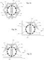
- FIG. 1 Referring to Figure 1 together with Figures 2a, 2b and 2c a flash device 200 similar to that in Figure 1 is shown in use.
- the flash device 200 of Figures 2a, 2b and 2c has a first light emission unit 208a and second light emission unit 208b and further light emission units 208c, 208d, 208e, 208f.
- Each of the first light emission unit 208a, second light emission unit 208b and further light emission units 208c, 208d, 208e, 208f are arranged around the surface of the housing 102 of the flash device 200 such that the aforementioned light emission units 208a-f emit a respective first optical output 214a, a second optical output 214b and further optical outputs 214c, 214d, 214e, 214f from the flash device 200 as required.
- the flash device 200 is activated by engaging an activation switch 118. In other example embodiments the flash device 200 may be activated remotely or by removing a safety device such as a pin or tag, or by being removed from a charging unit or housing.
- the user deploys the flash device 200 into the environment in which it is to be utilised.
- the sensor unit 210 captures real-time environment information 116 which in this embodiment is the orientation of the flash device 200 and the proximity of the flash device 200 to objects and surfaces such as walls and floors.
- This environment information 116 is used by the processor 206 together with the known geometry of the flash device 200 to generate an emission profile which determines whether the aforementioned light emission units 208a-f are instructed to output their respective first optical output 214a second optical output 214b and further optical outputs 214c-f.
- the flash device 200 has been deployed into the environment in which it is to be utilised and the sensor unit 210 has captured real-time environment information 116 which includes information from the proximity sensor that shows that the flash device 200 is not in close proximity to surfaces such as walls and the floor. Therefore, in this embodiment the emission profile generated by the processor 206 results in the first light emission unit 208a, second light emission unit 208b and further light emission units 208c-f outputting their respective first optical output 214a, second optical output 214b and further optical outputs 214c-f. These optical outputs 214a-f in turn disorientate any targets within the range of the optical outputs 214a-f.
- the light emission units 208a-f have an optical output beam divergence of ⁇ 120deg full width half max (FWHM) with each optical output 214a-f overlapping, in the far field, with its adjacent optical outputs 214a-f. This ensures that the intensity of optical output 214a-f of the flash device 200 is uniform with angle.
- FWHM full width half max
- Figure 2b shows the flash device 200 is in contact with a surface 222 and in close proximity to a wall 224.
- the sensor unit 210 again captures real-time environment information 116 which indicates that the flash device 200 is in close proximity to the wall 224 and the surface 222.
- the real-time environment information 116 is used by the processor 206 to determine that the further light emission units 208c-208f will not emit an optical output as they are obstructed.
- the processor 206 generates a second emission profile which only activates the first light emission unit 208a and second light emission unit 208b. Therefore, energy stored in the energy store 204 will not be used to power further light emission units 208c-f, which do not contribute to the disorientation of a target. This means that the flash device 200 will be able to operate for longer than would be the case if all the light emission units 208a-f were activated.
- Figure 2c shows the flash device 200 has moved away from the wall 224 but is still in close proximity to the surface 222.
- the sensor unit 210 again captures real-time environment information 116 which is transmitted to the processor 206 which generates a third emission profile as light emission unit 208f is no longer obstructed. Therefore, the first light emission unit 208a, second light emission unit 208b and further light emission unit 208f can output their respective first optical output 214a, second optical output 214b and further optical output 214f to disorientate any targets in the environment. Due to the proximity of the surface 222 further light emission units 208c-e will not output their respective further optical outputs 214c-e.
- energy stored in the energy store 204 will not be used to power further light emission units 208c-e which are not going to contribute to the disorientation of a target, and the flash device 200 will be able to operate for longer than would be the case if all the light emission units 208a-f were activated.
- the optimisation of the optical output of the flash device 200 based on the real-time environment information 116 transmitted from the sensor 210 to the processor 206 ensures the energy store 204 maintains the optical output of the flash device 200 for longer than if all the light emission units 208a-f were outputting their respective optical outputs 214a-f continuously.
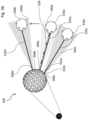
- FIGS 3a and 3b show an example embodiment of the flash device 300. While certain features are magnified to aid the explanation of the operation of the flash device 300, the skilled person will appreciate that the flash device 300 is not required to be of the relative size depicted in order to function a described.
- Figure 3a shows a flash device 300 which has been deployed in an area comprising a mixture of potentially hostile 330b, 330c and friendly 330a people.
- the surface of the flash device 300 comprises multiple light emission units, however, for clarity only a first light emission unit 308a, a second light emission unit 308b, a third light emission unit 308c are labelled.
- the surface of the flash device 300 further comprises a multiple sensors 310a-c connected to a sensor unit (not shown).
- the first light emission unit 308a, second light emission unit 308b a third light emission unit 308c and further light emission units 308n of the flash device 300 each output an exploratory optical signal 326a, 326b, 326c into the environment.
- the exploratory optical signals 326a, 326b, 326c are transmitted into the environment and exploratory optical signal 326a encounters an optical tag (not shown) which is being worn by a friendly person 330a.
- the optical tag comprises a photo-luminescent material which absorbs the wavelength of the exploratory optical signal 326a and returns a unique signature 328 with a high signal to noise ratio in the form of a different wavelength to that of the exploratory optical signal 326a.
- the unique signature 328 is subsequently detected by a first sensor 310a and enables the flash device 300 to determine that it is likely that friendly person 330a is in the range of the optical output of the flash device 300 as well as the likely position of the friendly person 330a in relation to the flash device 300.
- a unique signature is not detected by a second sensor 310b or a third sensor 310c in the flash device thus further enabling the flash device 300 to determine the likely position of the friendly person 330a in relation to the flash device.
- exploratory signals 326b, 326c are transmitted such that they could be detected by additional optical tags worn by other people 330b, 330c, further unique signatures are not detected by the sensors 310a, 310b, 310c as there are no other optical tags in the vicinity of the flash device 300.
- the flash device 300 processes the information received by first, second and third sensors 310a, 310b, 310c and based on this information, together with information which defines an action to be performed when a unique signature 328 is detected, generates an emission profile.
- the flash device 300 is configured not to transmit an optical output into a region of an environment where a unique signature 328 is detected. As a result, the flash device 300 does not activate the first light emission unit 308a which covers the first region 340a of the environment occupied by the friendly person 330a.
- the flash device 300 does activate a second light emission unit 308b which covers the second region 340b of the environment occupied by the other person 330b and activates a third light emission unit 308c which covers the third region 340c of the environment occupied by further person 330c, such that they output an optical output which distracts and disorients the other person 330b and further person 330c degrading their ability to act due to dazzle and/or inducing flash blindness.
- the flash device 300 is able to distinguish between friendly 330a and potentially hostile 330b, 330c people and disorientate the potentially hostile 330b, 330c people whilst significantly reducing the risk of disorientation of friendly 330a people, i.e. in this example, those wearing an optical tag enabled to transmit a unique signature 328 recognisable by the flash device 300.
- the beam divergence of the exploratory optical signals 326a, 326b, 326c is shown to be relatively narrow, this is merely for diagrammatic purposes, to distinguish the exploratory optical signals 326a, 326b, 326c from the regions of the environment 340a, 340b, 340c.
- the beam divergence of the exploratory signals is sufficient to cover the whole of the region of the environment.
- a series of narrower exploratory optical signals may be transmitted in a pattern which covers a region broader than would be covered by a single narrow exploratory optical signal. This pattern may be implemented using a number of techniques including beam steering optics within the flash device 300.
- Figure 3b shows the same arrangement as Figure 3a but the other person 330b has moved position, as shown by the arrow, in order to attempt to move from away from the optical output from the second light emission unit 308b.
- exploratory signal 326d output by a fourth light emission unit 308d has not detected a unique signature in the fourth region 340d
- the other person 330b is still disorientated by the optical output from the fourth light emission unit 308d.
- the second light emission unit 308b is not activated but in alternative embodiments the second light emission unit 308b is still activated.
- Figure 3c shows the same arrangement as Figure 3a but the other person 330b has moved into the first region 340a, which is currently occupied by the friendly person 340a.
- the flash device 300 has identified, using the information from the first, second and third sensors 310a, 310b, 310c that the other person 330b has moved region and this has resulted in the beam divergence of optical output 326e of the second light emission unit 308b being reduced due to the proximity of the other person 330b to the friendly person 340a.
- the optical output 326e is sufficient to fully cover the persons face at a distance of 1m.
- the beam divergence of optical output 326e is provided by beam conditioning optics (not shown).
- the beam conditioning optics may include a mechanical moving lens arrangement, a micro-mechanical (MEMS) lens arrangement, a liquid lens, a liquid crystal lens, a metamaterial lens.
- MEMS micro-mechanical
- the friendly person 330a is wearing an optical tag which identifies them to the flash device 300 as a friendly and the flash device 300 does not activate light emission units in the region of the friendly person 300a.
- an optical tag which identifies them to the flash device 300 as a friendly and the flash device 300 does not activate light emission units in the region of the friendly person 300a.
- potentially hostile people could be identified with optical tags, or both friendly and hostile people could be identified with different optical tags.
- the flash device may be programmed to avoid flash blinding people with cooperative optical tags and target those only with non-cooperative optical tags.
- the optical tag may be a retroreflector comprising a narrow line interference filter.
- flash devices 200, 300 shown are spherical in shape, other shapes could be envisaged, for example, cylindrical.
- Figure 4 shows an alternative embodiment where a number of flash devices 400a, 400b are used for an area denial application.
- the flash devices 400a, 400b are used at the entrance/exit 422 of a compound 450.
- the flash devices 400a, 400b are similar to the flash device 300 of figures 3a and 3b but are placed in static positions either side of the entrance/exit 422.
- the flash devices 400a, 400b are configured to activate when a potential hostile person or vehicle approaches the compound 450, represented by the arrows 430a, 430b, 430c.
- Figure 4 shows that due to the number and heading of potential hostiles 430a, 430b detected by sensor units including proximity sensors (not shown) of flash device 400a the device is activating multiple light emission units facing away from the compound 450.
- the sensor units including proximity sensors (not shown) of flash device 400b have resulted in the activation of multiple light emission units of flash device 400b which are facing away from the compound 450.
- Light emissions units of flash device 440b which face away from the compound 450 but do not contribute to the disorientation of potentially hostile targets 430b, 430c are not activated.
- static embodiments could be placed in locations other than entrances and exits, for example, corridors, offices and other secure areas.
- the flash devices will monitor the number of regions in the environment which friendly people are operating within, but when potentially hostile people enter the environment, the flash device is activated in the regions where the potentially hostile people are present causing disorientation. This enables those friendly people within the environment that are not targeted by the flash device to escape the area or apprehend the potentially hostile people.
- FIG. 5 shows a flash device 500 similar to those in previous example embodiments.
- the flash device 500 has been activated in an environment comprising a number of people 530a, 530b, 530c two of which are hostile.
- Many features of the flash device 500 operate in the same way as the flash deice 300 of figures 3a , 3b and 3c , however, the flash device 500 differs in that the sensors 510a, 510b, 510c comprise filters (not shown) which detect a reflection of the exploratory optical signal 526b, 526c in the second region 540b and third region 540c which indicate the use of protective eyewear.
- the flash device 500 changes the wavelength of the optical output provided by the second light emission unit 508b in the second region 540b and optical output provided by the third light emission unit 508c in third region 540c in order to reduce the effectiveness of the protective eyewear, thereby ensuring that the potentially hostile people 530b, 530c are dazzled, disoriented and disabled.
- Alternative embodiments of all the above example flash devices may comprise light emission units comprising LEDs, laser diodes and/or supercontinuum white light lasers, or a combination of the same.
- Each of the light emission units may comprise single or multiple filters which enable the LEDs, laser diodes and/or supercontinuum white light lasers to emit an optical output across a selective number of different wavelengths.
- Alternative embodiments of the above example flash devices may be arranged to adjust the beam divergence, range and intensity of the optical output depending on the nature of the potentially hostile target. For example a potentially hostile vehicle may be targeted with a larger beam divergence than a potentially hostile individual. The beam divergence may be adjusted using conditioning optics applied to individual or groups of light emission units. The beam range may also be adjusted together with the threshold of the sensors so that certain types of target are dazzled, disoriented and disabled at different distances away from the flash device. For example, flash devices may activate in the direction of vehicles earlier than for people on foot. Alternatively the above example flash devices may activate a greater number of light emission units for different types of target, thus creating a broader optical output.
- processing of the environment information may occur externally to the flash device and the emission profile or instructions to activate specific light emission units are transmitted to the flash device by a wired or wireless link.
- the at least one sensor unit may not be co-located with the light emission unit.
- the at least one sensor unit may provide environment information to the light emission unit using a wired or wireless connection.
- the flash device may include a camera type sensor and identify friendly and/or potentially hostile people using facial recognition or other physical or behavioural characteristics.
- the camera type sensor may also be able to identify types of vehicle or individual vehicles using, for example, number plate recognition technology.
- Alternative example embodiments may be configured such that not all light emission units are arranged to output an exploratory optical signal.
- Alternative example embodiments may be configured such that not all light emission units can output optical signals configured to disorientate, dazzle and disable targets.
- flash devices in addition to hand deployed flash devices and flash devices arranged statically, other embodiments may include a flash device deployed as a projectile munition from a launch device or a vehicle based flash device, including unmanned vehicles.
Landscapes
- Engineering & Computer Science (AREA)
- General Engineering & Computer Science (AREA)
- Radar, Positioning & Navigation (AREA)
- Remote Sensing (AREA)
- Chemical & Material Sciences (AREA)
- Combustion & Propulsion (AREA)
- Physics & Mathematics (AREA)
- Optics & Photonics (AREA)
- Optical Communication System (AREA)
Priority Applications (2)
| Application Number | Priority Date | Filing Date | Title |
|---|---|---|---|
| EP23275173.5A EP4571237A1 (de) | 2023-12-13 | 2023-12-13 | Blitzgerät |
| PCT/GB2024/052911 WO2025125773A1 (en) | 2023-12-13 | 2024-11-15 | Flash device |
Applications Claiming Priority (1)
| Application Number | Priority Date | Filing Date | Title |
|---|---|---|---|
| EP23275173.5A EP4571237A1 (de) | 2023-12-13 | 2023-12-13 | Blitzgerät |
Publications (1)
| Publication Number | Publication Date |
|---|---|
| EP4571237A1 true EP4571237A1 (de) | 2025-06-18 |
Family
ID=89222621
Family Applications (1)
| Application Number | Title | Priority Date | Filing Date |
|---|---|---|---|
| EP23275173.5A Pending EP4571237A1 (de) | 2023-12-13 | 2023-12-13 | Blitzgerät |
Country Status (1)
| Country | Link |
|---|---|
| EP (1) | EP4571237A1 (de) |
Citations (3)
| Publication number | Priority date | Publication date | Assignee | Title |
|---|---|---|---|---|
| US20110188031A1 (en) * | 2006-04-10 | 2011-08-04 | Elta Systems Ltd. | Distributed jammer system |
| US20160356438A1 (en) * | 2015-06-04 | 2016-12-08 | Gerald J. Matson | Tactical light apparatus |
| US20210270577A1 (en) * | 2018-11-02 | 2021-09-02 | Diehl Stiftung & Co. Kg | Method for operating an electronic dazzling element, and electronic dazzling element |
-
2023
- 2023-12-13 EP EP23275173.5A patent/EP4571237A1/de active Pending
Patent Citations (3)
| Publication number | Priority date | Publication date | Assignee | Title |
|---|---|---|---|---|
| US20110188031A1 (en) * | 2006-04-10 | 2011-08-04 | Elta Systems Ltd. | Distributed jammer system |
| US20160356438A1 (en) * | 2015-06-04 | 2016-12-08 | Gerald J. Matson | Tactical light apparatus |
| US20210270577A1 (en) * | 2018-11-02 | 2021-09-02 | Diehl Stiftung & Co. Kg | Method for operating an electronic dazzling element, and electronic dazzling element |
Similar Documents
| Publication | Publication Date | Title |
|---|---|---|
| US7982662B2 (en) | Scanning array for obstacle detection and collision avoidance | |
| US5255167A (en) | Finger mounted laser spotlight | |
| EP3095710B1 (de) | Dynamische äussere flugzeugbeleuchtungseinheit und verfahren zum betrieb einer dynamischen äusseren flugzeugbeleuchtungseinheit | |
| EP3014211B1 (de) | Adaptiver mehrwellenlängen-laserbeleuchter | |
| US20240288247A1 (en) | Systems and Methods for Generating Optical Beam Arrays | |
| US20060234191A1 (en) | Auto-aiming dazzler | |
| EP2789213B1 (de) | Leuchte | |
| EP2553379B1 (de) | Blender | |
| US20090219961A1 (en) | Laser Systems and Methods Having Auto-Ranging and Control Capability | |
| US20210254936A1 (en) | Electronic dazzling element | |
| US8051761B1 (en) | System and methods for broad area visual obscuration | |
| EP4571237A1 (de) | Blitzgerät | |
| US11555674B2 (en) | Dazzling system coupled to a camera mounted in a fixed location | |
| WO2025125773A1 (en) | Flash device | |
| US11552444B2 (en) | Infrared laser system | |
| US12197205B2 (en) | UAV guidance system and hand control unit | |
| KR102171144B1 (ko) | 보호 장치를 구비하는 레이저 시스템 | |
| EP2440877B1 (de) | An einem gewehr montierte optische einheit | |
| US20210239437A1 (en) | Light shield device | |
| WO2025122941A1 (en) | Multi-zone multi-target system | |
| JP6931562B2 (ja) | オブジェクトの視覚的な覆い隠し及びレーザー兵器のエネルギー消散のためのシステム | |
| US11519701B2 (en) | Device for disrupting binocular vision | |
| US20250327646A1 (en) | Multifunction portable illumination system | |
| WO2021050810A1 (en) | Dazzling system coupled to a camera mounted in a fixed location | |
| RU216889U1 (ru) | Устройство пассивной защиты от беспилотных летательных аппаратов |
Legal Events
| Date | Code | Title | Description |
|---|---|---|---|
| PUAI | Public reference made under article 153(3) epc to a published international application that has entered the european phase |
Free format text: ORIGINAL CODE: 0009012 |
|
| STAA | Information on the status of an ep patent application or granted ep patent |
Free format text: STATUS: THE APPLICATION HAS BEEN PUBLISHED |
|
| AK | Designated contracting states |
Kind code of ref document: A1 Designated state(s): AL AT BE BG CH CY CZ DE DK EE ES FI FR GB GR HR HU IE IS IT LI LT LU LV MC ME MK MT NL NO PL PT RO RS SE SI SK SM TR |