EP4570594A2 - Global headlamp - Google Patents
Global headlamp Download PDFInfo
- Publication number
- EP4570594A2 EP4570594A2 EP25173097.4A EP25173097A EP4570594A2 EP 4570594 A2 EP4570594 A2 EP 4570594A2 EP 25173097 A EP25173097 A EP 25173097A EP 4570594 A2 EP4570594 A2 EP 4570594A2
- Authority
- EP
- European Patent Office
- Prior art keywords
- headlamp
- vehicle
- jurisdiction
- emissive elements
- light source
- Prior art date
- Legal status (The legal status is an assumption and is not a legal conclusion. Google has not performed a legal analysis and makes no representation as to the accuracy of the status listed.)
- Pending
Links
Images






Classifications
-
- B—PERFORMING OPERATIONS; TRANSPORTING
- B60—VEHICLES IN GENERAL
- B60Q—ARRANGEMENT OF SIGNALLING OR LIGHTING DEVICES, THE MOUNTING OR SUPPORTING THEREOF OR CIRCUITS THEREFOR, FOR VEHICLES IN GENERAL
- B60Q1/00—Arrangement of optical signalling or lighting devices, the mounting or supporting thereof or circuits therefor
- B60Q1/02—Arrangement of optical signalling or lighting devices, the mounting or supporting thereof or circuits therefor the devices being primarily intended to illuminate the way ahead or to illuminate other areas of way or environments
- B60Q1/04—Arrangement of optical signalling or lighting devices, the mounting or supporting thereof or circuits therefor the devices being primarily intended to illuminate the way ahead or to illuminate other areas of way or environments the devices being headlights
- B60Q1/14—Arrangement of optical signalling or lighting devices, the mounting or supporting thereof or circuits therefor the devices being primarily intended to illuminate the way ahead or to illuminate other areas of way or environments the devices being headlights having dimming means
- B60Q1/1415—Dimming circuits
- B60Q1/1423—Automatic dimming circuits, i.e. switching between high beam and low beam due to change of ambient light or light level in road traffic
- B60Q1/143—Automatic dimming circuits, i.e. switching between high beam and low beam due to change of ambient light or light level in road traffic combined with another condition, e.g. using vehicle recognition from camera images or activation of wipers
-
- B—PERFORMING OPERATIONS; TRANSPORTING
- B60—VEHICLES IN GENERAL
- B60Q—ARRANGEMENT OF SIGNALLING OR LIGHTING DEVICES, THE MOUNTING OR SUPPORTING THEREOF OR CIRCUITS THEREFOR, FOR VEHICLES IN GENERAL
- B60Q1/00—Arrangement of optical signalling or lighting devices, the mounting or supporting thereof or circuits therefor
- B60Q1/02—Arrangement of optical signalling or lighting devices, the mounting or supporting thereof or circuits therefor the devices being primarily intended to illuminate the way ahead or to illuminate other areas of way or environments
- B60Q1/04—Arrangement of optical signalling or lighting devices, the mounting or supporting thereof or circuits therefor the devices being primarily intended to illuminate the way ahead or to illuminate other areas of way or environments the devices being headlights
- B60Q1/06—Arrangement of optical signalling or lighting devices, the mounting or supporting thereof or circuits therefor the devices being primarily intended to illuminate the way ahead or to illuminate other areas of way or environments the devices being headlights adjustable, e.g. remotely-controlled from inside vehicle
- B60Q1/08—Arrangement of optical signalling or lighting devices, the mounting or supporting thereof or circuits therefor the devices being primarily intended to illuminate the way ahead or to illuminate other areas of way or environments the devices being headlights adjustable, e.g. remotely-controlled from inside vehicle automatically
- B60Q1/085—Arrangement of optical signalling or lighting devices, the mounting or supporting thereof or circuits therefor the devices being primarily intended to illuminate the way ahead or to illuminate other areas of way or environments the devices being headlights adjustable, e.g. remotely-controlled from inside vehicle automatically due to special conditions, e.g. adverse weather, type of road, badly illuminated road signs or potential dangers
-
- F—MECHANICAL ENGINEERING; LIGHTING; HEATING; WEAPONS; BLASTING
- F21—LIGHTING
- F21S—NON-PORTABLE LIGHTING DEVICES; SYSTEMS THEREOF; VEHICLE LIGHTING DEVICES SPECIALLY ADAPTED FOR VEHICLE EXTERIORS
- F21S41/00—Illuminating devices specially adapted for vehicle exteriors, e.g. headlamps
- F21S41/10—Illuminating devices specially adapted for vehicle exteriors, e.g. headlamps characterised by the light source
- F21S41/14—Illuminating devices specially adapted for vehicle exteriors, e.g. headlamps characterised by the light source characterised by the type of light source
- F21S41/141—Light emitting diodes [LED]
- F21S41/151—Light emitting diodes [LED] arranged in one or more lines
-
- B—PERFORMING OPERATIONS; TRANSPORTING
- B60—VEHICLES IN GENERAL
- B60Q—ARRANGEMENT OF SIGNALLING OR LIGHTING DEVICES, THE MOUNTING OR SUPPORTING THEREOF OR CIRCUITS THEREFOR, FOR VEHICLES IN GENERAL
- B60Q2300/00—Indexing codes for automatically adjustable headlamps or automatically dimmable headlamps
- B60Q2300/30—Indexing codes relating to the vehicle environment
-
- B—PERFORMING OPERATIONS; TRANSPORTING
- B60—VEHICLES IN GENERAL
- B60Q—ARRANGEMENT OF SIGNALLING OR LIGHTING DEVICES, THE MOUNTING OR SUPPORTING THEREOF OR CIRCUITS THEREFOR, FOR VEHICLES IN GENERAL
- B60Q2300/00—Indexing codes for automatically adjustable headlamps or automatically dimmable headlamps
- B60Q2300/30—Indexing codes relating to the vehicle environment
- B60Q2300/31—Atmospheric conditions
- B60Q2300/314—Ambient light
-
- B—PERFORMING OPERATIONS; TRANSPORTING
- B60—VEHICLES IN GENERAL
- B60Q—ARRANGEMENT OF SIGNALLING OR LIGHTING DEVICES, THE MOUNTING OR SUPPORTING THEREOF OR CIRCUITS THEREFOR, FOR VEHICLES IN GENERAL
- B60Q2300/00—Indexing codes for automatically adjustable headlamps or automatically dimmable headlamps
- B60Q2300/30—Indexing codes relating to the vehicle environment
- B60Q2300/33—Driving situation
-
- B—PERFORMING OPERATIONS; TRANSPORTING
- B60—VEHICLES IN GENERAL
- B60Q—ARRANGEMENT OF SIGNALLING OR LIGHTING DEVICES, THE MOUNTING OR SUPPORTING THEREOF OR CIRCUITS THEREFOR, FOR VEHICLES IN GENERAL
- B60Q2300/00—Indexing codes for automatically adjustable headlamps or automatically dimmable headlamps
- B60Q2300/30—Indexing codes relating to the vehicle environment
- B60Q2300/33—Driving situation
- B60Q2300/331—Driving situation characterised by the driving side, e.g. on the left or right hand side
-
- B—PERFORMING OPERATIONS; TRANSPORTING
- B60—VEHICLES IN GENERAL
- B60Q—ARRANGEMENT OF SIGNALLING OR LIGHTING DEVICES, THE MOUNTING OR SUPPORTING THEREOF OR CIRCUITS THEREFOR, FOR VEHICLES IN GENERAL
- B60Q2300/00—Indexing codes for automatically adjustable headlamps or automatically dimmable headlamps
- B60Q2300/40—Indexing codes relating to other road users or special conditions
- B60Q2300/43—Indexing codes relating to other road users or special conditions following vehicle
-
- B—PERFORMING OPERATIONS; TRANSPORTING
- B60—VEHICLES IN GENERAL
- B60Q—ARRANGEMENT OF SIGNALLING OR LIGHTING DEVICES, THE MOUNTING OR SUPPORTING THEREOF OR CIRCUITS THEREFOR, FOR VEHICLES IN GENERAL
- B60Q2300/00—Indexing codes for automatically adjustable headlamps or automatically dimmable headlamps
- B60Q2300/40—Indexing codes relating to other road users or special conditions
- B60Q2300/45—Special conditions, e.g. pedestrians, road signs or potential dangers
Definitions
- the present invention relates to a vehicular system. More specifically, this invention relates to a region-adjustable vehicle headlamp.
- Headlamps such as headlights on a front of a vehicle
- headlamps are a fundamental tool to enhance safety of persons within the vehicle and also outside of the vehicle.
- light from the vehicle's headlamps allows for illumination of the world to enhance visibility for persons within the vehicle.
- the light allows for identification of the vehicle by persons outside of the vehicle as the vehicle moves about the world.
- This dual purpose of the headlamp e.g., seeing and being seen
- a vehicle's headlamps may project asymmetric light to illuminate proceeding vehicles and pedestrians while substantially minimizing glare to oncoming traffic.
- ECE Economic Commission for Europe
- HAT National Highway Traffic Safety Administration
- United States vehicles may use headlamp propagations as defined by FMVSS108.
- US 2005/073853 A1 discloses a system for controlling at least one exterior vehicle light of a controlled vehicle includes an array of sensors and a control unit.
- the array of sensors is capable of detecting light levels in front of the controlled vehicle.
- the control unit is in communication with the array of sensors and the at least one exterior vehicle light and determines a distance and an angle from the at least one exterior vehicle light of the controlled vehicle to a leading vehicle.
- the control unit is operable to control operation of the at least one exterior vehicle light as a function of the distance and angle, based on the output from the array of sensors, and prevent the at least one exterior vehicle light from providing a disruptive glare to a driver of the leading vehicle.
- EP 1 433 655 A2 discloses a digital lighting apparatus for a vehicle, which employs a reflection digital light deflector (2), includes a storage unit (4) that stores digital data of a plurality of light distribution patterns and a controller (6).
- the controller (6) selects digital data corresponding to a predetermined light distribution pattern from among the digital data stored in the storage unit (4) and controls the reflection digital light deflector (2), and illuminates a road surface with the predetermined light distribution pattern.
- US 2013/258689 A1 discloses a light-emitting device that includes a light-emitting section, a lens, and a movement control section, the movement control section changing an illumination position and a spot size of a laser beam in the light-emitting section by changing a relative position of the lens with respect to the light-emitting section.
- DE 10 2016 003 814 A1 describes a motor vehicle with at least one headlight, a determination device for determining in which of at least two states the motor vehicle is currently located and a first storage device or an access option to a first storage device with data stored therein of the maximum light intensity permissible in the at least two states in the center of the light beam emitted by the headlight or the headlights or the emitted light beams (and/or a light distribution of the headlight or the headlights with at least one lighting function.
- the control device is designed to automatically control the one or the several switched on headlights based on the current location of the motor vehicle in one of the at least two states in such a way that a maximum light intensity permissible for the state in which the motor vehicle is currently located in the center of the light beam or the emitted light beams emitted by the headlight or the headlights and/or a permissible light distribution of the headlight or the headlights is given for at least one lighting function.
- DE 10 2013 104 276 A1 describes a method for adapting at least one illumination parameter of an illumination device in at least one local illumination section of the illumination range of a lighting function in front of a vehicle, comprising the following steps: monitoring an actual value (I) of the illumination in at least one local illumination section of the illumination range, comparing the actual value (I) with a target value (S) for the illumination in this at least one local illumination section, adapting at least one illumination parameter of the illumination device to at least partially compensate for a difference between the actual value (I) and the target value (S) in this at least one local illumination section.
- US 2017/273159 A1 discloses a method, executed by a computer, which includes receiving extent information for a light zone and a desired emitted light level for a light source proximate to the light zone where the light source is a programmable light source, determining that the light source projects light onto the light zone, and adjusting, by one or more processors, the light source to emit the desired emitted light level.
- One embodiment is a computer-implemented method performed by a headlamp controller included in a vehicle.
- the headlamp controller may be configured to control a headlamp of the vehicle by a method that includes: obtaining configuration information indicative of a jurisdiction associated with the vehicle; accessing headlamp state information comprising a plurality of headlamp states; determining a current headlamp state of the plurality of headlamp states based on the configuration information; and causing outputting, via a pixelated light source in the headlamp, of a propagation based on the current headlamp state, the propagation representing a particular beam pattern which is compliant with the jurisdiction.
- the system may include: a memory storing headlamp state information for a plurality of jurisdictions and a selection of a current jurisdiction; a controller that reads the selected current jurisdiction and the headlamp state information associated with the selected jurisdiction; and a plurality of emissive elements configured to output propagations that are compliant with the selected jurisdiction based on the headlamp state information.
- Yet another embodiment is a headlamp controller included in a vehicle, the headlamp controller controlling a headlamp of the vehicle, and the headlamp controller comprising one or more processing elements which are configured to: obtain configuration information indicative of a jurisdiction associated with the vehicle; determine a current headlamp state based on the configuration information; and cause outputting, via a pixelated light source in the headlamp, of a propagation based on the current headlamp state, the propagation representing a particular beam pattern which is compliant with the jurisdiction.
- the global headlamp may use a pixelated light source as its light source.
- the pixelated light source may represent an arrangement of emissive elements.
- the pixelated light source may have a threshold number of rows (e.g., 3 rows, 4, rows, 5 rows) each with a particular number of emissive elements.
- the rows may have a same, or different, number of emissive elements.
- An example embodiment of the pixelated lights source described herein with respect to Figure 1B has four rows, in which a first and second row have 28 emissive elements (e.g., rows 116A, 116B), a third row has 24 emissive elements (e.g., row 116C), and a fourth row has 22 emissive elements (e.g., row 116D).
- each emissive element may be separately addressable or may be addressable in groups.
- the global headlamp described above may output light which complies with the requirements for automobile beam patterns specified by regulatory agencies of different jurisdictions.
- Light which forms a particular beam pattern, beam shape, projection, and so on, is referred to herein as a propagation.
- the global headlamp may be configured to output a first low-beam propagation used by vehicles in the United States and complying with automobile or other vehicle regulatory requirements of the United States.
- the global headlamp may be configured to output a second low-beam propagation used by vehicles in the European Union and complying with regulatory requirements for vehicles in the European Union.
- a jurisdiction may set requirements for one or more countries or regions associated with the jurisdiction.
- a first subset of the emissive elements may be used to output light.
- Each emissive element in the first subset may output light with a particular intensity or intensity relative to each other. Intensity may represent, in some embodiments, luminous intensity.
- the particular intensity of an LED may be adjusted according to the current through the LED (e.g., the luminous intensity may be adjusted).
- a second subset of the emissive element maybe used to output light. This second subset may include different emissive elements as compared to the first subset.
- the second subset may include the same emissive elements as the first subset and output light with different intensities or relative intensities as compared to the emissive elements in the first subset.
- a headlamp controller of a vehicle may be used to update a headlamp's propagation in substantially real-time.
- the headlamp controller may update a headlamp state which indicates a particular propagation to be used.
- the headlamp controller may determine that the vehicle is in a first jurisdiction (e.g., the United Kingdom).
- the vehicle may travel to a second jurisdiction (e.g., France).
- the headlamp controller may obtain configuration information indicative of a headlamp state.
- Example configuration information may include a location of the vehicle. Based on the configuration information, the vehicle may update the headlamp state to be associated with the second jurisdiction.
- a same jurisdiction may set different requirements for countries or regions associated with the jurisdiction. For example, a jurisdiction may set requirements for a first country which drives on the left hand side of the road which may be distinct from requirements for a second country which drives on the right hand side of the road.
- the techniques described herein enable a global headlamp capable of being used around the world.
- the global headlamp may therefore simplify the manufacturing of a vehicle, since the same headlamp may be utilized in any country.
- a bill of materials may be reduced from three or more light source variants to one light source (e.g., the pixelated light source).
- the headlamp controller may allow for an enhanced user experience when utilizing a vehicle.
- the headlamp controller may allow for seamless transitions between jurisdictions.
- the headlamp controller may allow an employee of a manufacturer to easily specify a headlamp state prior to delivery to a buyer. In this way, vehicles may be shipped around the world without physical alteration of the vehicle's headlamp.
- FIG. 1A illustrates a block diagram of an example vehicle 100 setting headlamp states 112A-B of headlamps 110A-110B based on configuration information 106 indicative of a jurisdiction.
- the headlamps 110A-110B may use pixelated light sources as will be described in Figure 1B .
- the vehicle 100 may include a vehicle processor 104 to control functionality or operation of the vehicle 100.
- the processor 104 may provide information to one or more other systems included in the vehicle 100 (e.g., via one or more data buses).
- the other systems may relate to heating, ventilation, and air condition (HVAC) functionality, self-driving functionality, electric vehicle battery monitoring / control, and so on.
- HVAC heating, ventilation, and air condition
- the processor 104 may additionally obtain information from one or more sensors (e.g., global navigation satellite system sensor, camera), one or more antennas, and so on.
- sensors e.g., global navigation satellite system sensor, camera
- the vehicle 100 further includes headlamp controllers 102A-102B which control respective headlamps 110A-110B on the vehicle 100.
- the headlamp controllers 102A-102B may represent processing elements (e.g., processors, FPGAs, ASICs, and so on).
- the headlamp controllers 102A-102B may also represent the electronic control unit (ECU) described in U.S. Prov. App. No. 63/043467 , and International Application No. PCT/US2021/038658 , which are hereby incorporated herein by reference in their entirety.
- one headlamp controller may be used to control the headlamps 110A-110B.
- the headlamp controllers 102A-102B may set current headlamp states 112A-112B for the headlamps 110A-110B.
- a headlamp state may cause a headlamp to output a particular propagation.
- the headlamp state may cause the headlamp to output light which projects a particular beam pattern.
- the headlamp controllers 102A-102B may specify headlamp states 112A-112B from a multitude of states.
- the headlamp states may represent permutations which cause a headlamp to output a propagation which is compliant with a particular jurisdiction's regulatory rules.
- the multitude of states may therefore represent all headlamp states which are compliant with any jurisdiction's regulatory rules.
- headlamp controller 102A may cause headlamp 110A to output a low-beam propagation which is compliant with regulatory rules in the United States.
- headlamp controller 102A may cause headlamp 110A to output a high-beam propagation which is compliant with those same rules.
- the headlamp controllers 102A-102B may use configuration information 106.
- the configuration information 106 is indicative of a jurisdiction, such that the headlamp states 112A-112B may be in compliance with the jurisdiction.
- Example configuration information 106 may include a current location of the vehicle 100 (e.g., based on GNSS information received from the vehicle processor 104 and/or a GNSS sensor).
- the headlamp controllers' 102A-102B may select headlamp states 112A-112B which are compliant with a jurisdiction which regulates the location.
- the headlamp states 112A-112B may also be specific to a low-beam or high-beam state.
- Configuration information 106 may also include a homologation region associated with the vehicle 100.
- the homologation region may represent a summary of countries which enforce specific rules (e.g., countries in a same jurisdiction). Homologation region may be based on a country variable to logically select applicable states (also referred to as a country code).
- the homologation region may be set during manufacture of the vehicle 100. For example, a country variable may be set for the vehicle or another identifier indicative of a jurisdiction.
- the headlamp controllers 102A-102B may select headlamp states 112A-112B which are compliant with the homologation region. In this way, manufacturing of the vehicle 100 may be simplified. For example, the same headlamp controllers 102A-102B and headlamps 110A-110B may be used to manufacture vehicles regardless of region.
- the above-described homologation region may be specified to cause a vehicle to conform to regulations in one of the regions.
- the homologation region may be stored in a protected portion of memory or stored in a read-only memory of the vehicle processor 104.
- a particular password, authentication key, private key, and so on may be required.
- the vehicle 100 may determine that its current location is outside of the specified homologation region. For example, a driver of the vehicle 100 may have driven, or otherwise transported, the vehicle 100 to a country in a different homologation region.
- the vehicle 100 may obtain location information via a global navigation satellite system (GNSS) location. Based on the GNSS location, the vehicle 100 may identify that the vehicle 100 is in a different homologation region.
- the vehicle 100 may provide its location to an outside system via a network (e.g., via a cellular network or Wi-Fi). In response, the outside system may indicate a homologation region for the vehicle's 100 location.
- GNSS global navigation satellite system
- the vehicle 100 may thus identify that different headlamp states 112A-112B should be selected, such that the vehicle is compliant with regulations of the different homologation region (e.g., different jurisdiction).
- the vehicle 100 may automatically update the headlamp states 112A-112B and may optionally present information to the user indicating the updating.
- the vehicle 100 may request that the driver confirm that the headlamp states 112A-112B are to be updated.
- the vehicle 100 may include a display which is responsive to user input.
- the vehicle processor 104 may cause presentation of a user interface via the display.
- the user interface may request that the driver confirm the headlamps 110A-110B are to output different propagations.
- the user interface may present a graphical depiction of the different propagations (e.g., as compared to a current propagation).
- the user interface may present the example illustrations in Figures 4A-4C in contrast to Figures 5A-5C . In this way, the driver may view a difference between low-beam propagations between, for example, the United States and Europe.
- the headlamp states 112A-112B may thus cause the headlamps 110A-110B to output propagations which satisfy regulations for a particular jurisdiction.
- the headlamp states 112A-112B may cause the propagations to be either low-beam propagations or high-beam propagations.
- the driver of the vehicle 100 may provide input to the vehicle 100 to indicate that either high-beams or low-beams are to be utilized.
- the vehicle processor 104 may identify when to use high-beams or low-beams (e.g., the processor 104 may implement an automatic high beam). For example, if there is no oncoming traffic the vehicle processor 104 may select high-beams. In this example, if oncoming traffic is detected by the vehicle processor 104 (e.g., via a radar or camera), then low-beams may be selected.
- the headlamp controllers 102A-102B may enforce secondary requirements.
- Example secondary requirements may include fault states defined by regulatory agencies associated with a jurisdiction. The headlamp controllers 102A-102B may therefore ensure that the headlamps conform to any such defined fault states.
- the headlamps can potentially still output propagations.
- the headlamps may still be allowed to operate if a portion of the emissive elements in a pixelated light source experience failure (e.g., cease outputting light or have reduced light).
- the headlamp controllers 102A-102B may determine if the remaining functional emissive elements still meet requirements associated with the jurisdiction. If so, the headlamp controllers 102A-102B may output headlamp states 112A-112B which cause the headlamps 110A-110B to output light.
- the vehicle processor 104 may update a display to indicate that the headlamps 110A-110B are experiencing failure or error. However, if the headlamp controllers 102A-102B identify that the remaining emissive elements are unable to satisfy the requirements, the controllers 102A-102B may turn off the headlamps. Similarly, the vehicle processor 104 may update the display to indicate that the headlamps 110A-110B are unable to function and that the driver should call for assistance.
- the headlamp controllers 102A-102B may enforce combinations of lighting. For example, in a first jurisdiction (e.g., the United States) it may not be allowed to have high-beams and fog beams activated at a same time. In this example, the headlamp controllers 102A-102B may therefore disallow fog beams when high-beams are activated. In contrast, in a second jurisdiction (e.g., Europe) this combination may be allowed. The headlamp controllers 102A-102B may therefore ensure that such secondary requirements are satisfied regardless of jurisdiction in the world. In contrast, prior techniques relied upon hard-coded rules which implement a single jurisdiction's secondary requirements.
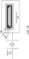
- FIG. 1B illustrates a detailed view of an example pixelated light source 120A for a headlamp 110A.
- the illustrated pixelated light source 120A includes an array of emissive elements (e.g., rows 1161A-116D). These emissive elements may be included on a printed circuit board (PCB) and light from the emissive elements may be provided to one or more optical elements for routing to a real-world environment.
- the illustrated headlamp may represent the left hand side (LHS) headlamp 110A of Figure 1A .
- the pixelated light source 120A may be utilized, without modification, for either a left hand side or right hand side headlamp on a vehicle.
- a headlamp controller may cause a pixelated light source to output a particular propagation depending on which side of the vehicle the pixelated light is located.
- a specific pixelated light source may be specific to a side of a vehicle.
- the headlamp state 112A may cause headlamp 110A to output a propagation which is compliant with a particular jurisdiction.
- the state 112A may also cause the headlamp 110A to output either a low-beam or high-beam propagation.
- the pixelated light source 120A may cause activation of particular emissive elements to generate the propagation.
- Example activations of emissive elements for different propagations are illustrated in Figures 4A-4C .
- the emissive elements may include light emitting diodes (LEDs), micro-LEDs, organic LEDs, and so on.
- a pixel e.g., as described below
- a pixel may be associated with a respective emissive element.
- a pixel may be associated with a multitude of emissive elements (e.g., a multitude of micro-LEDs may form one pixel).
- the headlamp state 112A may indicate pixel information 114A.
- the headlamp state 112A may be provided via bus, such as a controller area network (CAN) bus, optionally via one or more messages on the bus.
- CAN controller area network
- headlamp controller 102A may have stored information indicating pixels which are to be used for any jurisdiction's propagation. In this example, the controller 102A may thus be able to define pixels for a high-beam or low-beam propagation which is compliant with a particular jurisdiction.
- the stored information may optionally be stored in a look up table (e.g., in volatile or non-volatile memory, such as in the headlamp controller or processor).
- the look up table may store values for each pixel utilized for a propagation.
- the values may indicate intensities, or relative intensities, for the pixels (e.g., luminous intensities).
- the look up table may indicate values (e.g., luminous intensity values) of emissive elements for any headlamp state.
- the pixel information 114A may reflect values for the emissive elements of the pixelated light source 120A.
- the pixel information 114A may additionally be specific to a particular side of the pixelated light source.
- the pixel information 114A may reflect pixel values for a left hand side pixelated light source.
- a left hand side headlamp may output a propagation specific to the left hand side while a right hand side headlamp may output a propagation specific to the right hand side.
- Example propagations for a left hand side headlamp and a right hand side headlamp are illustrated in Figures 4A-4B .
- the headlamp state 112A may be provided periodically, such as every threshold number of microseconds or milliseconds.
- the headlamp state 112A may optionally set values of registers associated with the emissive elements. Based on these values, certain shunts utilized by LED drivers may be selected. In this way, a subset of the emissive elements may be selected. Intensity of the light, such as luminous intensity, which is output by the emissive elements in the subset may be defined, as an example, by respective duty cycles associated with the LED drivers. Luminous intensity may also be defined, as an example, based on measures of continuous current being provided to respective emissive elements. Information regarding shunts and outputting intensities is included in U.S. Prov. App. No. 63/043467 and International Application No. PCT/US2021/038658 , which are hereby incorporated herein by reference in its entirety.
- the headlamp state 112A may also be provided as information for the pixelated light source 120A to enforce.
- the pixel information 114A may be analyzed by a processing element included in the pixelated light source 120A.
- the light source 120A may then cause a subset of the emissive elements to be activated.
- the headlamp state 112A may be updated and the light source 120A may enforce the update.
- a driver or vehicle may select low-beam from a prior high-beam state.
- the vehicle may have been transported to a new jurisdiction.
- Example rows 116A-116D of the pixelated light source 120A are illustrated.
- a first two rows 116A-116B may be used for low-beam propagations.
- a third and fourth row 116C-116D may be activated for high-beam propagations.
- emissive elements there may be additional rows of emissive elements.
- a certain row or a portion thereof may include emissive elements which output infrared or ultraviolet light.
- a vehicle processor e.g., processor 104
- these non-visible, or substantially non-visible, emissive elements may be positioned above visible emissive elements.
- row 116A may represent visible emissive elements and above that may be included a row of a same size which has non-visible emissive elements.
- the pixel information 114A may correspond to luminous intensity values for the pixels of the pixelated light source 120A.
- these pixel values may be modified by a scaling factor.
- the vehicle 100 may detect that an ambient light outside is above a threshold measure.
- the pixel information 114A may be uniformly increased in intensity by a scaling factor.
- the scaling factor may optionally depend on jurisdiction. For example, a first jurisdiction may allow scaling (e.g., Europe, such as defined in ECE R123).
- the intensity values may additionally be updated based on the vehicle 100 turning. For example, certain emissive elements may be increased in intensity while other emissive elements are retained in intensity or reduced.
- Figure 2 illustrates an example process 200 for setting a headlamp state based on configuration information.
- a headlamp controller obtains configuration information 106 and use the information 106 to define a headlamp state.
- the configuration information 106 may include a homologation region (e.g., jurisdiction) as described in Figure 1A .
- the configuration information 106 may also include a vehicle drive side. As may be appreciated, a particular jurisdiction may allow for driving on both sides of the road depending on location within the particular jurisdiction.
- the configuration information 106 may further include the vehicle's current location according to an antenna or GNSS sensor.
- Configuration information 106 may further include vehicle model and variant.
- the headlamp controller may be configured for use in a multitude of vehicle models.
- the headlamp controller may select a regional configuration based on stored information for all global headlamp states. As an example, the headlamp controller may identify that the vehicle is to use European regulations for a left-hand traffic vehicle. The headlamp controller may receive a headlamp state request and select the headlamp state as described in Figures 1A-1B .
- the headlamp state may cause a particular propagation to be output by a headlamp.
- the headlamp state may cause a headlamp to output a low-beam propagation which is compliant with a jurisdiction.
- a driver of the vehicle may have selected use of low-beams or the vehicle may have automatically selected low-beams.
- the headlamp controller may enforce secondary requirements such as fault states as described above.
- the headlamp state may cause particular emissive elements of a pixelated light source to be utilized.
- Particular intensities, such as luminous intensities, for the emissive elements may be additionally be set.
- the pixelated light source may be configured to output a multitude of propagations to allow for global usage.
- Figure 3 illustrates an example process 300 for a headlamp controller to cause output of light from a headlamp which confirms to a particular jurisdiction.
- this process 300 will be described as being performed by a headlamp controller (e.g., controller 110A).
- vehicle processor 104 may provide information to a pixelated light source such that controller 110A is not utilized or required.
- vehicle processor 104 may perform some, or all, of the blocks included in process 300.
- the headlamp controller obtains configuration information.
- the configuration information may be provided by one or more vehicle processors.
- certain configuration information may be defined during manufacture of a vehicle. For example, a homologation region may be set for the vehicle.
- the vehicle model, vehicle variant, and optionally vehicle drive side may be set during manufacture.
- Other configuration information such as the real-time location, may be determined during use of the vehicle (e.g., by the vehicle processor 104 or headlamp controller).
- the homologation region and/or drive side may thus be updated based on the real-time location. For example, if the vehicle is driven or transported to a different jurisdiction, the real-time location will reflect the different jurisdiction (e.g., as determined by the processor 104 or headlamp controller).
- the vehicle may then prompt the driver to confirm that the headlamps are to be updated accordingly.
- the prompt may be provided via a user interface presented on a display included in the vehicle or the prompt may be provided via speech (e.g., the driver may respond affirmatively to the speech).
- the vehicle may update the homologation region and/or drive side.
- the headlamp controller accesses headlamp state information.
- the headlamp controller may have access to headlamp state information in stored memory. For example, look up tables may be used to define pixel values for a multitude of propagations which are compliant with different jurisdictions.
- the headlamp controller determines a current headlamp state.
- the headlamp controller may determine a particular jurisdiction to which the headlamps are to conform. For example, the headlamp controller may determine a current location of the vehicle based on the configuration information (e.g., the processor 104 may determine the location and provide information to the headlamp controller usable to select a jurisdiction). Additionally, the headlamp controller may determine whether the low-beams or high-beams are activated. Based on this information, the headlamp controller may select a headlamp state which is compliant with the jurisdiction and which causes output of a compliant low-beam or high-beam propagation.
- the headlamp controller causes output of a headlamp propagation based on the headlamp state.
- the headlamp controller may cause activation of particular emissive elements in the pixelated light source to generate a particular propagation.
- the headlamp controller may allow for a left handed traffic low-beam propagation in a first jurisdiction to be output via a same headlamp as a right handed traffic high-beam propagation in a second jurisdiction.
- the headlamp controller or vehicle processor may determine a beam shape which corresponds to a headlamp state for the homologation region and/or drive side.
- the beam shape may be translated by the processor or headlamp controller into particular pixels (e.g., luminous intensity values for the pixels).
- the state information may be updated via over the air (OTA) updates.
- OTA over the air
- the headlamp controller may optionally be specific to a side of the vehicle, such that the headlamp state is specific to the side of the vehicle (e.g., left side, right side).
- the headlamp state may indicate propagations for the left side and rights ide and the headlamp controller may use the propagation for its corresponding side.
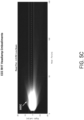
- Figures 4A-4C illustrate an example low beam state generated by a pixelated light source which is compliant with a first jurisdiction.
- the example jurisdiction is the United States (e.g., FMVSS).
- Figures 4A-4C illustrate an example road with a vehicle driving on the right-hand side.
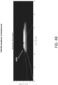
- Figure 4A illustrates a first headlamp using a pixelated light source outputting light 402A from a subset of emissive elements.
- the light source is outputting a low-beam propagation for the left hand side headlamp.
- the illustrated cutoff 404 may represent a transition for an illuminated area to a non-illuminated area.
- the cutoff 404 may extend along an upper length of the propagation separation the illuminated and non-illuminated areas.
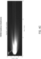
- Figure 4B illustrates a second headlamp using a pixelated light source outputting light 402B from a subset of emissive elements.
- the light source is outputting a low-beam propagation for the right hand side headlamp.
- Figure 4C illustrates a combination of the first headlamp and second headlamp of Figures 4A-4B .
- a propagation 402C associated with a low-beam state for the first jurisdiction is included.
- Figures 5A-5C illustrate an example low beam state generated by a pixelated light source which is compliant with a second jurisdiction.
- the example jurisdiction is Europe for right-hand traffic driving.
- Figures 5A-5C thus illustrate an example road with a vehicle driving on the right-hand side.
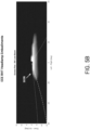
- Figure 5A illustrates a first headlamp using a pixelated light source outputting light 502A from a subset of emissive elements.
- the light source is outputting a low-beam propagation for the left hand side headlamp.
- the illustrated cutoff 504 may represent a transition for an illuminated area to a non-illuminated area.
- the cutoff 504 may extend along an upper length of the propagation separation the illuminated and non-illuminated areas.
- Figure 5B illustrates a second headlamp using a pixelated light source outputting light 502B from a subset of emissive elements.
- the light source is outputting a low-beam propagation for the right hand side headlamp.
- Figure 5C illustrates a combination of the first headlamp and second headlamp of Figures 5A-5B .
- a propagation 502C associated with a low-beam state for the second jurisdiction is included.
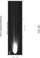
- Figures 6A-6C illustrate an example low beam state generated by a pixelated light source which is compliant with a third jurisdiction.
- the example jurisdiction is Europe (e.g., the same as the above-described second jurisdiction) but for left-hand traffic driving.
- Figures 6A-6C thus illustrate an example road with a vehicle driving on the left-hand side.
- Figure 6A illustrates a first headlamp using a pixelated light source outputting light 602A from a subset of emissive elements.
- the light source is outputting a low-beam propagation for the left hand side headlamp.
- the illustrated cutoff 604 may represent a transition for an illuminated area to a non-illuminated area.
- the cutoff 604 may extend along an upper length of the propagation separation the illuminated and non-illuminated areas.
- Figure 6B illustrates a second headlamp using a pixelated light source outputting light 602B from a subset of emissive elements.
- the light source is outputting a low-beam propagation for the right hand side headlamp.
- Figure 6C illustrates a combination of the first headlamp and second headlamp of Figures 6A-6B .
- a propagation 602C associated with a low-beam state for the third jurisdiction is included.
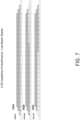
- Figure 7 illustrates an example pixelated light source outputting different low beam states 702A-7042C.
- the low beam state 702A for the United States may include activation of emissive elements on a first row.
- the low beam states 702B-702C for Europe may include activation of emissive elements on a first and a second row.
- FIGS 4A-4C , 5A-5C , and 6A-6C illustrate example low-beam states
- high-beam states may be generated by the pixelated lights source for different jurisdictions.
- the high-beam states may include activation of emissive elements in the upper third and/or fourth rows of the pixelated light source.
- the global headlamp described herein may represent a single headlamp positioned on a front of a vehicle.
- the single headlamp may include emissive elements which extend substantially across a front of the vehicle.
- the single headlamp may output light which forms propagations for both the left side and the right side of the vehicle.
- All of the processes described herein may be embodied in, and fully automated, via software code modules executed by a computing system that includes one or more computers or processors.
- the code modules may be stored in any type of non-transitory computer-readable medium or other computer storage device. Some or all the methods may be embodied in specialized computer hardware.
- a processor can be a microprocessor, but in the alternative, the processor can be a controller, microcontroller, or state machine, combinations of the same, or the like.
- a processor can include electrical circuitry configured to process computer-executable instructions.
- a processor includes an FPGA or other programmable device that performs logic operations without processing computer-executable instructions.
- a processor can also be implemented as a combination of computing devices, for example, a combination of a DSP and a microprocessor, a plurality of microprocessors, one or more microprocessors in conjunction with a DSP core, or any other such configuration.
- a processor may also include primarily analog components.
- some or all of the signal processing algorithms described herein may be implemented in analog circuitry or mixed analog and digital circuitry.
- a computing environment can include any type of computer system, including, but not limited to, a computer system based on a microprocessor, a mainframe computer, a digital signal processor, a portable computing device, a device controller, or a computational engine within an appliance, to name a few.
- Disjunctive language such as the phrase "at least one of X, Y, or Z," unless specifically stated otherwise, is understood with the context as used in general to present that an item, term, etc., may be either X, Y, or Z, or any combination thereof (for example, X, Y, and/or Z). Thus, such disjunctive language is not generally intended to, and should not, imply that certain embodiments require at least one of X, at least one of Y, or at least one of Z to each be present.
- a device configured to are intended to include one or more recited devices. Such one or more recited devices can also be collectively configured to carry out the stated recitations.
- a processor configured to carry out recitations A, B and C can include a first processor configured to carry out recitation A working in conjunction with a second processor configured to carry out recitations B and C.
- a computer-implemented method performed by a headlamp controller included in a vehicle, the headlamp controller configured to control a headlamp of the vehicle, and the method comprising: obtaining configuration information indicative of a jurisdiction associated with the vehicle; accessing headlamp state information comprising a plurality of headlamp states; determining a current headlamp state of the plurality of headlamp states based on the configuration information; and causing output, via a pixelated light source in the headlamp, of a propagation based on the current headlamp state, the propagation representing a particular beam pattern which is compliant with the jurisdiction.
- the configuration information may comprise one or more of a homologation region, a vehicle drive side, a current location of the vehicle, a vehicle model, or a vehicle variant.
- the headlamp state information may comprise the plurality of headlamp states stored in respective look up tables, wherein the look up tables define values for pixels of the pixelated light source.
- the headlamp state information may be specific to a side of the vehicle on which the headlamp is positioned.
- the current headlamp state may be selected to be compliant with the jurisdiction.
- the current headlamp state may be associated with a high-beam or low-beam propagation.
- the headlamp controller may enforce secondary requirements for the jurisdiction.
- the pixelated light source may comprise a plurality of emissive elements, and wherein the propagation is generated via light being output from a subset of the emissive elements.
- the pixelated light source may be configured to output propagations which are compliant with a multitude of jurisdictions.
- a vehicular system for propagating light that complies with requirements of multiple jurisdictions
- the vehicular system comprising: a memory storing headlamp state information for a plurality of jurisdictions and a selection of a current jurisdiction; a controller that reads the selected current jurisdiction and the headlamp state information associated with the selected jurisdiction; and a plurality of emissive elements configured to output propagations that are compliant with the selected jurisdiction based on the headlamp state information.
- the memory may store for each jurisdiction, luminous intensity values for a respective subset of the emissive elements, and wherein the memory .
- the memory may store the luminous intensity values in a look up table.
- the headlamp state information ma indicate a low-beam state or a high-beam state.
- the selection of the current jurisdiction may be based on a current location of the vehicular system.
- the plurality of emissive elements may be formed in a plurality of rows, and wherein the output propagations cause activation of a respective subset of the emissive elements.
- a first output propagation associated with a low-beam state for the selected current jurisdiction may cause activation of first emissive elements included in a first threshold number of rows, and wherein a second output propagation associated with a high-beam state for the selected current jurisdiction may cause activation of second emissive elements included a second threshold number of rows, and wherein the second threshold is greater than the first threshold.
- a headlamp controller is included in a vehicle, the headlamp controller controlling a headlamp of the vehicle, and the headlamp controller comprising one or more processing elements which are configured to: obtain configuration information indicative of a jurisdiction associated with the vehicle; determine a current headlamp state based on the configuration information; and cause output, via a pixelated light source in the headlamp, of a propagation based on the current headlamp state, the propagation representing a particular beam pattern which is compliant with the jurisdiction.
- the configuration information may comprise one or more of a homologation region, a vehicle drive side, a current location of the vehicle, a vehicle model, or a vehicle variant.
- the processing elements may access headlamp state information comprising a plurality of headlamp states stored in respective look up tables, wherein the current headlamp state is selected from the plurality of headlamp states, and wherein the look up tables define values for pixels of the pixelated light source.
- the headlamp controller may further comprise memory configured to store a plurality of headlamp states.
Landscapes
- Engineering & Computer Science (AREA)
- Mechanical Engineering (AREA)
- Physics & Mathematics (AREA)
- Microelectronics & Electronic Packaging (AREA)
- Optics & Photonics (AREA)
- General Engineering & Computer Science (AREA)
- Lighting Device Outwards From Vehicle And Optical Signal (AREA)
Abstract
Description
- The present invention relates to a vehicular system. More specifically, this invention relates to a region-adjustable vehicle headlamp.
- Headlamps, such as headlights on a front of a vehicle, are a fundamental tool to enhance safety of persons within the vehicle and also outside of the vehicle. For example, light from the vehicle's headlamps allows for illumination of the world to enhance visibility for persons within the vehicle. As another example, the light allows for identification of the vehicle by persons outside of the vehicle as the vehicle moves about the world. This dual purpose of the headlamp (e.g., seeing and being seen) may inform a particular propagation (e.g., beam pattern or projection) of the light output by each headlight. As an example, a vehicle's headlamps may project asymmetric light to illuminate proceeding vehicles and pedestrians while substantially minimizing glare to oncoming traffic.
- Different jurisdictions, such as countries or geographical regions, have different regulatory agencies or standard settings organization which specify regulations regarding these projections. As an example, European vehicles have headlights which conform to regulations specified by the Economic Commission for Europe (ECE). As another example, vehicles in the United States have headlights which conform to the Federal Motor Vehicle Safety Standards specified by the National Highway Traffic Safety Administration (NHTSA). In this example, United States vehicles may use headlamp propagations as defined by FMVSS108.
- Due to these jurisdictional differences, global vehicle entities manufacture different headlamps for the different jurisdictions. For example, different jurisdictional regulations may be in conflict with each other, such that different headlamps are required for the different jurisdictions. Additionally, within a single jurisdiction there may be variation due to the handedness of the driver. As an example, certain countries within the European Union (e.g., the United Kingdom, Ireland) drive on the left side of the road while certain other countries in the European Union (e.g., Germany, France) drive on the right side of the road.
-
US 2005/073853 A1 discloses a system for controlling at least one exterior vehicle light of a controlled vehicle includes an array of sensors and a control unit. The array of sensors is capable of detecting light levels in front of the controlled vehicle. The control unit is in communication with the array of sensors and the at least one exterior vehicle light and determines a distance and an angle from the at least one exterior vehicle light of the controlled vehicle to a leading vehicle. The control unit is operable to control operation of the at least one exterior vehicle light as a function of the distance and angle, based on the output from the array of sensors, and prevent the at least one exterior vehicle light from providing a disruptive glare to a driver of the leading vehicle.
EP 1 433 655 A2 discloses a digital lighting apparatus for a vehicle, which employs a reflection digital light deflector (2), includes a storage unit (4) that stores digital data of a plurality of light distribution patterns and a controller (6). The controller (6) selects digital data corresponding to a predetermined light distribution pattern from among the digital data stored in the storage unit (4) and controls the reflection digital light deflector (2), and illuminates a road surface with the predetermined light distribution pattern.
US 2013/258689 A1 discloses a light-emitting device that includes a light-emitting section, a lens, and a movement control section, the movement control section changing an illumination position and a spot size of a laser beam in the light-emitting section by changing a relative position of the lens with respect to the light-emitting section.
DE 10 2016 003 814 A1 describes a motor vehicle with at least one headlight, a determination device for determining in which of at least two states the motor vehicle is currently located and a first storage device or an access option to a first storage device with data stored therein of the maximum light intensity permissible in the at least two states in the center of the light beam emitted by the headlight or the headlights or the emitted light beams (and/or a light distribution of the headlight or the headlights with at least one lighting function. The control device is designed to automatically control the one or the several switched on headlights based on the current location of the motor vehicle in one of the at least two states in such a way that a maximum light intensity permissible for the state in which the motor vehicle is currently located in the center of the light beam or the emitted light beams emitted by the headlight or the headlights and/or a permissible light distribution of the headlight or the headlights is given for at least one lighting function.
DE 10 2013 104 276 A1 describes a method for adapting at least one illumination parameter of an illumination device in at least one local illumination section of the illumination range of a lighting function in front of a vehicle, comprising the following steps: monitoring an actual value (I) of the illumination in at least one local illumination section of the illumination range, comparing the actual value (I) with a target value (S) for the illumination in this at least one local illumination section, adapting at least one illumination parameter of the illumination device to at least partially compensate for a difference between the actual value (I) and the target value (S) in this at least one local illumination section.
US 2017/273159 A1 discloses a method, executed by a computer, which includes receiving extent information for a light zone and a desired emitted light level for a light source proximate to the light zone where the light source is a programmable light source, determining that the light source projects light onto the light zone, and adjusting, by one or more processors, the light source to emit the desired emitted light level. - The systems, methods, and devices of this invention each have several innovative aspects, no single one of which is solely responsible for all of the desirable attributes disclosed herein. The invention is defined in the claims.
- Although certain embodiments and examples are disclosed herein, inventive subject matter extends beyond the examples in the specifically disclosed embodiments to other alternative embodiments and/or uses, and to modifications and equivalents thereof.
- The details, including optional details, of one or more embodiments of the subject matter of this specification are set forth in the accompanying drawings and the description below. Other optional features, aspects, and advantages of the subject matter will become apparent from the description, the drawings, and the claims.
- One embodiment is a computer-implemented method performed by a headlamp controller included in a vehicle. The headlamp controller may be configured to control a headlamp of the vehicle by a method that includes: obtaining configuration information indicative of a jurisdiction associated with the vehicle; accessing headlamp state information comprising a plurality of headlamp states; determining a current headlamp state of the plurality of headlamp states based on the configuration information; and causing outputting, via a pixelated light source in the headlamp, of a propagation based on the current headlamp state, the propagation representing a particular beam pattern which is compliant with the jurisdiction.
- Another embodiment is a vehicular system for propagating light that complies with requirements of multiple jurisdictions. The system may include: a memory storing headlamp state information for a plurality of jurisdictions and a selection of a current jurisdiction; a controller that reads the selected current jurisdiction and the headlamp state information associated with the selected jurisdiction; and a plurality of emissive elements configured to output propagations that are compliant with the selected jurisdiction based on the headlamp state information.
- Yet another embodiment is a headlamp controller included in a vehicle, the headlamp controller controlling a headlamp of the vehicle, and the headlamp controller comprising one or more processing elements which are configured to: obtain configuration information indicative of a jurisdiction associated with the vehicle; determine a current headlamp state based on the configuration information; and cause outputting, via a pixelated light source in the headlamp, of a propagation based on the current headlamp state, the propagation representing a particular beam pattern which is compliant with the jurisdiction.
- Throughout the drawings, reference numbers are re-used to indicate correspondence between referenced elements. The drawings are provided to illustrate embodiments of the subject matter described herein and not to limit the scope thereof.
-
Figure 1A illustrates a block diagram of an example vehicle setting headlamp states based on configuration information indicative of a jurisdiction. -
Figure 1B illustrates a detailed view of an example pixelated light source for a headlamp. -
Figure 2 illustrates an example process for setting a headlamp state based on configuration information. -
Figure 3 illustrates an example process for a headlamp controller to cause output of light from a headlamp which confirms to a particular jurisdiction. -
Figures 4A-4C illustrate an example low beam state generated by a pixelated light source which is compliant with a first jurisdiction. -
Figures 5A-5C illustrate an example low beam state generated by a pixelated light source which is compliant with a second jurisdiction. -
Figures 6A-6C illustrate an example low beam state generated by a pixelated light source which is compliant with a third jurisdiction. -
Figure 7 illustrates an example pixelated light source outputting different low beam states. - Like reference numbers and designations in the various drawings indicate like elements.
- This specification describes, among other things, a global headlamp which is usable in any, or substantially any, of the world's countries. As will be described, the global headlamp may use a pixelated light source as its light source. In some embodiments, the pixelated light source may represent an arrangement of emissive elements. For example, the pixelated light source may have a threshold number of rows (e.g., 3 rows, 4, rows, 5 rows) each with a particular number of emissive elements. In this example, the rows may have a same, or different, number of emissive elements. An example embodiment of the pixelated lights source described herein with respect to
Figure 1B has four rows, in which a first and second row have 28 emissive elements (e.g.,rows row 116C), and a fourth row has 22 emissive elements (e.g.,row 116D). In some embodiments, each emissive element may be separately addressable or may be addressable in groups. - The global headlamp described above may output light which complies with the requirements for automobile beam patterns specified by regulatory agencies of different jurisdictions. Light which forms a particular beam pattern, beam shape, projection, and so on, is referred to herein as a propagation. As an example, the global headlamp may be configured to output a first low-beam propagation used by vehicles in the United States and complying with automobile or other vehicle regulatory requirements of the United States. As another example, the global headlamp may be configured to output a second low-beam propagation used by vehicles in the European Union and complying with regulatory requirements for vehicles in the European Union. Thus, and as may be appreciated, a jurisdiction may set requirements for one or more countries or regions associated with the jurisdiction.
- Outputting these different propagations, which are in compliance with different regulatory agencies, may be satisfied via control of the emissive elements in the pixelated light source. With respect to the first propagation, a first subset of the emissive elements may be used to output light. Each emissive element in the first subset may output light with a particular intensity or intensity relative to each other. Intensity may represent, in some embodiments, luminous intensity. As may be appreciated, the particular intensity of an LED may be adjusted according to the current through the LED (e.g., the luminous intensity may be adjusted). With respect to the second propagation, a second subset of the emissive element maybe used to output light. This second subset may include different emissive elements as compared to the first subset. Optionally, the second subset may include the same emissive elements as the first subset and output light with different intensities or relative intensities as compared to the emissive elements in the first subset.
- In one embodiment, a headlamp controller of a vehicle may be used to update a headlamp's propagation in substantially real-time. As referred to herein, the headlamp controller may update a headlamp state which indicates a particular propagation to be used. For example, the headlamp controller may determine that the vehicle is in a first jurisdiction (e.g., the United Kingdom). In this example, the vehicle may travel to a second jurisdiction (e.g., France). Optionally, the headlamp controller may obtain configuration information indicative of a headlamp state. Example configuration information may include a location of the vehicle. Based on the configuration information, the vehicle may update the headlamp state to be associated with the second jurisdiction. While a first and second jurisdiction are described above, in some embodiments a same jurisdiction may set different requirements for countries or regions associated with the jurisdiction. For example, a jurisdiction may set requirements for a first country which drives on the left hand side of the road which may be distinct from requirements for a second country which drives on the right hand side of the road.
- In this way, the techniques described herein enable a global headlamp capable of being used around the world. The global headlamp may therefore simplify the manufacturing of a vehicle, since the same headlamp may be utilized in any country. For example, a bill of materials may be reduced from three or more light source variants to one light source (e.g., the pixelated light source). Additionally, the headlamp controller may allow for an enhanced user experience when utilizing a vehicle. For example, the headlamp controller may allow for seamless transitions between jurisdictions. As another example, the headlamp controller may allow an employee of a manufacturer to easily specify a headlamp state prior to delivery to a buyer. In this way, vehicles may be shipped around the world without physical alteration of the vehicle's headlamp.
-
Figure 1A illustrates a block diagram of anexample vehicle 100 setting headlamp states 112A-B of headlamps 110A-110B based onconfiguration information 106 indicative of a jurisdiction. The headlamps 110A-110B may use pixelated light sources as will be described inFigure 1B . Thevehicle 100 may include avehicle processor 104 to control functionality or operation of thevehicle 100. For example, theprocessor 104 may provide information to one or more other systems included in the vehicle 100 (e.g., via one or more data buses). In this example, the other systems may relate to heating, ventilation, and air condition (HVAC) functionality, self-driving functionality, electric vehicle battery monitoring / control, and so on. Theprocessor 104 may additionally obtain information from one or more sensors (e.g., global navigation satellite system sensor, camera), one or more antennas, and so on. - In the illustrated embodiment, the
vehicle 100 further includesheadlamp controllers 102A-102B which control respective headlamps 110A-110B on thevehicle 100. Theheadlamp controllers 102A-102B may represent processing elements (e.g., processors, FPGAs, ASICs, and so on). Theheadlamp controllers 102A-102B may also represent the electronic control unit (ECU) described inU.S. Prov. App. No. 63/043467 PCT/US2021/038658 , which are hereby incorporated herein by reference in their entirety. In some embodiments, one headlamp controller may be used to control the headlamps 110A-110B. - The
headlamp controllers 102A-102B may set current headlamp states 112A-112B for the headlamps 110A-110B. As described above, a headlamp state may cause a headlamp to output a particular propagation. For example, the headlamp state may cause the headlamp to output light which projects a particular beam pattern. Theheadlamp controllers 102A-102B may specify headlamp states 112A-112B from a multitude of states. The headlamp states may represent permutations which cause a headlamp to output a propagation which is compliant with a particular jurisdiction's regulatory rules. The multitude of states may therefore represent all headlamp states which are compliant with any jurisdiction's regulatory rules. For example,headlamp controller 102A may cause headlamp 110A to output a low-beam propagation which is compliant with regulatory rules in the United States. As another example,headlamp controller 102A may cause headlamp 110A to output a high-beam propagation which is compliant with those same rules. - To specify the headlamp states 112A-112B, in some embodiments the
headlamp controllers 102A-102B may useconfiguration information 106. Theconfiguration information 106 is indicative of a jurisdiction, such that the headlamp states 112A-112B may be in compliance with the jurisdiction.Example configuration information 106 may include a current location of the vehicle 100 (e.g., based on GNSS information received from thevehicle processor 104 and/or a GNSS sensor). For thisexample configuration information 106, the headlamp controllers' 102A-102B may select headlamp states 112A-112B which are compliant with a jurisdiction which regulates the location. The headlamp states 112A-112B may also be specific to a low-beam or high-beam state. -
Configuration information 106 may also include a homologation region associated with thevehicle 100. For example, the homologation region may represent a summary of countries which enforce specific rules (e.g., countries in a same jurisdiction). Homologation region may be based on a country variable to logically select applicable states (also referred to as a country code). In some embodiments, the homologation region may be set during manufacture of thevehicle 100. For example, a country variable may be set for the vehicle or another identifier indicative of a jurisdiction. Thus, theheadlamp controllers 102A-102B may select headlamp states 112A-112B which are compliant with the homologation region. In this way, manufacturing of thevehicle 100 may be simplified. For example, thesame headlamp controllers 102A-102B and headlamps 110A-110B may be used to manufacture vehicles regardless of region. - During manufacture, the above-described homologation region may be specified to cause a vehicle to conform to regulations in one of the regions. In some embodiments, the homologation region may be stored in a protected portion of memory or stored in a read-only memory of the
vehicle processor 104. Optionally, to adjust the homologation region (e.g., as described inFigure 3 ) a particular password, authentication key, private key, and so on may be required. - In some embodiments the
vehicle 100 may determine that its current location is outside of the specified homologation region. For example, a driver of thevehicle 100 may have driven, or otherwise transported, thevehicle 100 to a country in a different homologation region. In this example, thevehicle 100 may obtain location information via a global navigation satellite system (GNSS) location. Based on the GNSS location, thevehicle 100 may identify that thevehicle 100 is in a different homologation region. In some embodiments, thevehicle 100 may provide its location to an outside system via a network (e.g., via a cellular network or Wi-Fi). In response, the outside system may indicate a homologation region for the vehicle's 100 location. - The
vehicle 100 may thus identify that different headlamp states 112A-112B should be selected, such that the vehicle is compliant with regulations of the different homologation region (e.g., different jurisdiction). Thevehicle 100 may automatically update the headlamp states 112A-112B and may optionally present information to the user indicating the updating. Optionally, thevehicle 100 may request that the driver confirm that the headlamp states 112A-112B are to be updated. For example, thevehicle 100 may include a display which is responsive to user input. In this example, thevehicle processor 104 may cause presentation of a user interface via the display. The user interface may request that the driver confirm the headlamps 110A-110B are to output different propagations. In some embodiments, the user interface may present a graphical depiction of the different propagations (e.g., as compared to a current propagation). As an example, the user interface may present the example illustrations inFigures 4A-4C in contrast toFigures 5A-5C . In this way, the driver may view a difference between low-beam propagations between, for example, the United States and Europe. - The headlamp states 112A-112B may thus cause the headlamps 110A-110B to output propagations which satisfy regulations for a particular jurisdiction. In addition, the headlamp states 112A-112B may cause the propagations to be either low-beam propagations or high-beam propagations. For example, the driver of the
vehicle 100 may provide input to thevehicle 100 to indicate that either high-beams or low-beams are to be utilized. As another example, thevehicle processor 104 may identify when to use high-beams or low-beams (e.g., theprocessor 104 may implement an automatic high beam). For example, if there is no oncoming traffic thevehicle processor 104 may select high-beams. In this example, if oncoming traffic is detected by the vehicle processor 104 (e.g., via a radar or camera), then low-beams may be selected. - In addition to causing output of particular propagations, the
headlamp controllers 102A-102B may enforce secondary requirements. Example secondary requirements may include fault states defined by regulatory agencies associated with a jurisdiction. Theheadlamp controllers 102A-102B may therefore ensure that the headlamps conform to any such defined fault states. - For example, and with respect to a particular jurisdiction (e.g., Europe), if the light source for the headlamps experiences a failure then the headlamps can potentially still output propagations. As an example, the headlamps may still be allowed to operate if a portion of the emissive elements in a pixelated light source experience failure (e.g., cease outputting light or have reduced light). For this example, the
headlamp controllers 102A-102B may determine if the remaining functional emissive elements still meet requirements associated with the jurisdiction. If so, theheadlamp controllers 102A-102B may output headlamp states 112A-112B which cause the headlamps 110A-110B to output light. Optionally, thevehicle processor 104 may update a display to indicate that the headlamps 110A-110B are experiencing failure or error. However, if theheadlamp controllers 102A-102B identify that the remaining emissive elements are unable to satisfy the requirements, thecontrollers 102A-102B may turn off the headlamps. Similarly, thevehicle processor 104 may update the display to indicate that the headlamps 110A-110B are unable to function and that the driver should call for assistance. - As another example of secondary requirements, the
headlamp controllers 102A-102B may enforce combinations of lighting. For example, in a first jurisdiction (e.g., the United States) it may not be allowed to have high-beams and fog beams activated at a same time. In this example, theheadlamp controllers 102A-102B may therefore disallow fog beams when high-beams are activated. In contrast, in a second jurisdiction (e.g., Europe) this combination may be allowed. Theheadlamp controllers 102A-102B may therefore ensure that such secondary requirements are satisfied regardless of jurisdiction in the world. In contrast, prior techniques relied upon hard-coded rules which implement a single jurisdiction's secondary requirements. -
Figure 1B illustrates a detailed view of an example pixelatedlight source 120A for a headlamp 110A. The illustrated pixelatedlight source 120A includes an array of emissive elements (e.g., rows 1161A-116D). These emissive elements may be included on a printed circuit board (PCB) and light from the emissive elements may be provided to one or more optical elements for routing to a real-world environment. The illustrated headlamp may represent the left hand side (LHS) headlamp 110A ofFigure 1A . The pixelatedlight source 120A may be utilized, without modification, for either a left hand side or right hand side headlamp on a vehicle. In this way, manufacturing may be simplified due to the pixelated light source being used in both headlamps of a vehicle and being capable of working globally. A headlamp controller may cause a pixelated light source to output a particular propagation depending on which side of the vehicle the pixelated light is located. In some embodiments, a specific pixelated light source may be specific to a side of a vehicle. - As described above, the
headlamp state 112A may cause headlamp 110A to output a propagation which is compliant with a particular jurisdiction. Thestate 112A may also cause the headlamp 110A to output either a low-beam or high-beam propagation. Based on thestate 112A, the pixelatedlight source 120A may cause activation of particular emissive elements to generate the propagation. Example activations of emissive elements for different propagations are illustrated inFigures 4A-4C . The emissive elements may include light emitting diodes (LEDs), micro-LEDs, organic LEDs, and so on. In some embodiments, a pixel (e.g., as described below) may be associated with a respective emissive element. In some embodiments, a pixel may be associated with a multitude of emissive elements (e.g., a multitude of micro-LEDs may form one pixel). - In some embodiments, the
headlamp state 112A may indicatepixel information 114A. Theheadlamp state 112A may be provided via bus, such as a controller area network (CAN) bus, optionally via one or more messages on the bus. For example,headlamp controller 102A may have stored information indicating pixels which are to be used for any jurisdiction's propagation. In this example, thecontroller 102A may thus be able to define pixels for a high-beam or low-beam propagation which is compliant with a particular jurisdiction. The stored information may optionally be stored in a look up table (e.g., in volatile or non-volatile memory, such as in the headlamp controller or processor). The look up table may store values for each pixel utilized for a propagation. The values may indicate intensities, or relative intensities, for the pixels (e.g., luminous intensities). For example, the look up table may indicate values (e.g., luminous intensity values) of emissive elements for any headlamp state. Thus, thepixel information 114A may reflect values for the emissive elements of the pixelatedlight source 120A. - The
pixel information 114A may additionally be specific to a particular side of the pixelated light source. In the illustrated embodiment, thepixel information 114A may reflect pixel values for a left hand side pixelated light source. As an example, a left hand side headlamp may output a propagation specific to the left hand side while a right hand side headlamp may output a propagation specific to the right hand side. Example propagations for a left hand side headlamp and a right hand side headlamp are illustrated inFigures 4A-4B . - The
headlamp state 112A may be provided periodically, such as every threshold number of microseconds or milliseconds. Theheadlamp state 112A may optionally set values of registers associated with the emissive elements. Based on these values, certain shunts utilized by LED drivers may be selected. In this way, a subset of the emissive elements may be selected. Intensity of the light, such as luminous intensity, which is output by the emissive elements in the subset may be defined, as an example, by respective duty cycles associated with the LED drivers. Luminous intensity may also be defined, as an example, based on measures of continuous current being provided to respective emissive elements. Information regarding shunts and outputting intensities is included in U.S. Prov. App. No.63/043467 PCT/US2021/038658 , which are hereby incorporated herein by reference in its entirety. - The
headlamp state 112A may also be provided as information for the pixelatedlight source 120A to enforce. For example, thepixel information 114A may be analyzed by a processing element included in the pixelatedlight source 120A. Thelight source 120A may then cause a subset of the emissive elements to be activated. At a subsequent time, theheadlamp state 112A may be updated and thelight source 120A may enforce the update. For example, a driver or vehicle may select low-beam from a prior high-beam state. As another example, the vehicle may have been transported to a new jurisdiction. -
Example rows 116A-116D of the pixelatedlight source 120A are illustrated. In some embodiments, a first tworows 116A-116B may be used for low-beam propagations. Optionally, a third andfourth row 116C-116D may be activated for high-beam propagations. - In some embodiments, there may be additional rows of emissive elements. Optionally, there may be rows with emissive elements which output light of different spectrums. For example, a certain row or a portion thereof may include emissive elements which output infrared or ultraviolet light. In this example, a vehicle processor (e.g., processor 104) may activate infrared lights based on a self-driving or autonomous mode being activated. In some embodiments, these non-visible, or substantially non-visible, emissive elements may be positioned above visible emissive elements. For example,
row 116A may represent visible emissive elements and above that may be included a row of a same size which has non-visible emissive elements. - As described above, the
pixel information 114A may correspond to luminous intensity values for the pixels of the pixelatedlight source 120A. In some embodiments, these pixel values may be modified by a scaling factor. For example, thevehicle 100 may detect that an ambient light outside is above a threshold measure. In this example, thepixel information 114A may be uniformly increased in intensity by a scaling factor. The scaling factor may optionally depend on jurisdiction. For example, a first jurisdiction may allow scaling (e.g., Europe, such as defined in ECE R123). The intensity values may additionally be updated based on thevehicle 100 turning. For example, certain emissive elements may be increased in intensity while other emissive elements are retained in intensity or reduced. -
Figure 2 illustrates anexample process 200 for setting a headlamp state based on configuration information. A headlamp controller obtainsconfiguration information 106 and use theinformation 106 to define a headlamp state. For example, theconfiguration information 106 may include a homologation region (e.g., jurisdiction) as described inFigure 1A . Theconfiguration information 106 may also include a vehicle drive side. As may be appreciated, a particular jurisdiction may allow for driving on both sides of the road depending on location within the particular jurisdiction. Theconfiguration information 106 may further include the vehicle's current location according to an antenna or GNSS sensor.Configuration information 106 may further include vehicle model and variant. For example, the headlamp controller may be configured for use in a multitude of vehicle models. - Based on the
configuration information 106, the headlamp controller may select a regional configuration based on stored information for all global headlamp states. As an example, the headlamp controller may identify that the vehicle is to use European regulations for a left-hand traffic vehicle. The headlamp controller may receive a headlamp state request and select the headlamp state as described inFigures 1A-1B . - As described above, the headlamp state may cause a particular propagation to be output by a headlamp. For example, the headlamp state may cause a headlamp to output a low-beam propagation which is compliant with a jurisdiction. In this example, a driver of the vehicle may have selected use of low-beams or the vehicle may have automatically selected low-beams. Additionally, the headlamp controller may enforce secondary requirements such as fault states as described above.
- With respect to a propagation, the headlamp state may cause particular emissive elements of a pixelated light source to be utilized. Particular intensities, such as luminous intensities, for the emissive elements may be additionally be set. In this way, the pixelated light source may be configured to output a multitude of propagations to allow for global usage.
-
Figure 3 illustrates anexample process 300 for a headlamp controller to cause output of light from a headlamp which confirms to a particular jurisdiction. For convenience, thisprocess 300 will be described as being performed by a headlamp controller (e.g., controller 110A). In some embodiments,vehicle processor 104 may provide information to a pixelated light source such that controller 110A is not utilized or required. Thus, in someembodiments vehicle processor 104 may perform some, or all, of the blocks included inprocess 300. - At
block 302, the headlamp controller obtains configuration information. As described above, the configuration information may be provided by one or more vehicle processors. In some embodiments, certain configuration information may be defined during manufacture of a vehicle. For example, a homologation region may be set for the vehicle. As another example, the vehicle model, vehicle variant, and optionally vehicle drive side may be set during manufacture. Other configuration information, such as the real-time location, may be determined during use of the vehicle (e.g., by thevehicle processor 104 or headlamp controller). - The homologation region and/or drive side may thus be updated based on the real-time location. For example, if the vehicle is driven or transported to a different jurisdiction, the real-time location will reflect the different jurisdiction (e.g., as determined by the
processor 104 or headlamp controller). The vehicle may then prompt the driver to confirm that the headlamps are to be updated accordingly. For example, the prompt may be provided via a user interface presented on a display included in the vehicle or the prompt may be provided via speech (e.g., the driver may respond affirmatively to the speech). Once updated, the vehicle may update the homologation region and/or drive side. - At
block 304, the headlamp controller accesses headlamp state information. The headlamp controller may have access to headlamp state information in stored memory. For example, look up tables may be used to define pixel values for a multitude of propagations which are compliant with different jurisdictions. - At
block 306, the headlamp controller determines a current headlamp state. The headlamp controller may determine a particular jurisdiction to which the headlamps are to conform. For example, the headlamp controller may determine a current location of the vehicle based on the configuration information (e.g., theprocessor 104 may determine the location and provide information to the headlamp controller usable to select a jurisdiction). Additionally, the headlamp controller may determine whether the low-beams or high-beams are activated. Based on this information, the headlamp controller may select a headlamp state which is compliant with the jurisdiction and which causes output of a compliant low-beam or high-beam propagation. - At
block 308, the headlamp controller causes output of a headlamp propagation based on the headlamp state. The headlamp controller may cause activation of particular emissive elements in the pixelated light source to generate a particular propagation. In this way, the headlamp controller may allow for a left handed traffic low-beam propagation in a first jurisdiction to be output via a same headlamp as a right handed traffic high-beam propagation in a second jurisdiction. - As another example, the headlamp controller or vehicle processor may determine a beam shape which corresponds to a headlamp state for the homologation region and/or drive side. The beam shape may be translated by the processor or headlamp controller into particular pixels (e.g., luminous intensity values for the pixels). In some embodiments, the state information may be updated via over the air (OTA) updates.
- The headlamp controller may optionally be specific to a side of the vehicle, such that the headlamp state is specific to the side of the vehicle (e.g., left side, right side). Optionally, the headlamp state may indicate propagations for the left side and rights ide and the headlamp controller may use the propagation for its corresponding side.
-
Figures 4A-4C illustrate an example low beam state generated by a pixelated light source which is compliant with a first jurisdiction. In the illustrated embodiment, the example jurisdiction is the United States (e.g., FMVSS).Figures 4A-4C illustrate an example road with a vehicle driving on the right-hand side. -
Figure 4A illustrates a first headlamp using a pixelated light source outputting light 402A from a subset of emissive elements. InFigure 4A the light source is outputting a low-beam propagation for the left hand side headlamp. The illustratedcutoff 404 may represent a transition for an illuminated area to a non-illuminated area. For example, thecutoff 404 may extend along an upper length of the propagation separation the illuminated and non-illuminated areas. -
Figure 4B illustrates a second headlamp using a pixelated light source outputting light 402B from a subset of emissive elements. InFigure 4B the light source is outputting a low-beam propagation for the right hand side headlamp. -
Figure 4C illustrates a combination of the first headlamp and second headlamp ofFigures 4A-4B . In the illustrated example, apropagation 402C associated with a low-beam state for the first jurisdiction is included. -
Figures 5A-5C illustrate an example low beam state generated by a pixelated light source which is compliant with a second jurisdiction. In the illustrated embodiment, the example jurisdiction is Europe for right-hand traffic driving.Figures 5A-5C thus illustrate an example road with a vehicle driving on the right-hand side. -
Figure 5A illustrates a first headlamp using a pixelated light source outputting light 502A from a subset of emissive elements. InFigure 5A the light source is outputting a low-beam propagation for the left hand side headlamp. The illustratedcutoff 504 may represent a transition for an illuminated area to a non-illuminated area. For example, thecutoff 504 may extend along an upper length of the propagation separation the illuminated and non-illuminated areas. -
Figure 5B illustrates a second headlamp using a pixelated light source outputting light 502B from a subset of emissive elements. InFigure 5B the light source is outputting a low-beam propagation for the right hand side headlamp. -
Figure 5C illustrates a combination of the first headlamp and second headlamp ofFigures 5A-5B . In the illustrated example, apropagation 502C associated with a low-beam state for the second jurisdiction is included. -
Figures 6A-6C illustrate an example low beam state generated by a pixelated light source which is compliant with a third jurisdiction. In the illustrated embodiment, the example jurisdiction is Europe (e.g., the same as the above-described second jurisdiction) but for left-hand traffic driving.Figures 6A-6C thus illustrate an example road with a vehicle driving on the left-hand side. -
Figure 6A illustrates a first headlamp using a pixelated light source outputting light 602A from a subset of emissive elements. InFigure 6A the light source is outputting a low-beam propagation for the left hand side headlamp. The illustratedcutoff 604 may represent a transition for an illuminated area to a non-illuminated area. For example, thecutoff 604 may extend along an upper length of the propagation separation the illuminated and non-illuminated areas. -
Figure 6B illustrates a second headlamp using a pixelated light source outputting light 602B from a subset of emissive elements. InFigure 6B the light source is outputting a low-beam propagation for the right hand side headlamp. -
Figure 6C illustrates a combination of the first headlamp and second headlamp ofFigures 6A-6B . In the illustrated example, apropagation 602C associated with a low-beam state for the third jurisdiction is included. -
Figure 7 illustrates an example pixelated light source outputting different low beam states 702A-7042C. As illustrated, thelow beam state 702A for the United States may include activation of emissive elements on a first row. The low beam states 702B-702C for Europe may include activation of emissive elements on a first and a second row. - While
Figures 4A-4C ,5A-5C , and6A-6C , illustrate example low-beam states, it may be appreciated that high-beam states may be generated by the pixelated lights source for different jurisdictions. The high-beam states, as an example, may include activation of emissive elements in the upper third and/or fourth rows of the pixelated light source. - Furthermore, in some embodiments the global headlamp described herein may represent a single headlamp positioned on a front of a vehicle. The single headlamp may include emissive elements which extend substantially across a front of the vehicle. Thus, the single headlamp may output light which forms propagations for both the left side and the right side of the vehicle.
- All of the processes described herein may be embodied in, and fully automated, via software code modules executed by a computing system that includes one or more computers or processors. The code modules may be stored in any type of non-transitory computer-readable medium or other computer storage device. Some or all the methods may be embodied in specialized computer hardware.
- Many other variations than those described herein will be apparent from this disclosure. For example, depending on the embodiment, certain acts, events, or functions of any of the algorithms described herein can be performed in a different sequence or can be added, merged, or left out altogether (for example, not all described acts or events are necessary for the practice of the algorithms). Moreover, in certain embodiments, acts or events can be performed concurrently, for example, through multi-threaded processing, interrupt processing, or multiple processors or processor cores or on other parallel architectures, rather than sequentially. In addition, different tasks or processes can be performed by different machines and/or computing systems that can function together.
- The various illustrative logical blocks and modules described in connection with the embodiments disclosed herein can be implemented or performed by a machine, such as a processing unit or processor, a digital signal processor (DSP), an application specific integrated circuit (ASIC), a field programmable gate array (FPGA) or other programmable logic device, discrete gate or transistor logic, discrete hardware components, or any combination thereof designed to perform the functions described herein. A processor can be a microprocessor, but in the alternative, the processor can be a controller, microcontroller, or state machine, combinations of the same, or the like. A processor can include electrical circuitry configured to process computer-executable instructions. In another embodiment, a processor includes an FPGA or other programmable device that performs logic operations without processing computer-executable instructions. A processor can also be implemented as a combination of computing devices, for example, a combination of a DSP and a microprocessor, a plurality of microprocessors, one or more microprocessors in conjunction with a DSP core, or any other such configuration. Although described herein primarily with respect to digital technology, a processor may also include primarily analog components. For example, some or all of the signal processing algorithms described herein may be implemented in analog circuitry or mixed analog and digital circuitry. A computing environment can include any type of computer system, including, but not limited to, a computer system based on a microprocessor, a mainframe computer, a digital signal processor, a portable computing device, a device controller, or a computational engine within an appliance, to name a few.
- Conditional language such as, among others, "can," "could," "might" or "may," unless specifically stated otherwise, are understood within the context as used in general to convey that certain embodiments include, while other embodiments do not include, certain features, elements and/or steps. Thus, such conditional language is not generally intended to imply that features, elements and/or steps are in any way required for one or more embodiments or that one or more embodiments necessarily include logic for deciding, with or without user input or prompting, whether these features, elements and/or steps are included or are to be performed in any particular embodiment.
- Disjunctive language such as the phrase "at least one of X, Y, or Z," unless specifically stated otherwise, is understood with the context as used in general to present that an item, term, etc., may be either X, Y, or Z, or any combination thereof (for example, X, Y, and/or Z). Thus, such disjunctive language is not generally intended to, and should not, imply that certain embodiments require at least one of X, at least one of Y, or at least one of Z to each be present.
- Any process descriptions, elements or blocks in the flow diagrams described herein and/or depicted in the attached figures should be understood as potentially representing modules, segments, or portions of code which include one or more executable instructions for implementing specific logical functions or elements in the process. Alternate implementations are included within the scope of the embodiments described herein in which elements or functions may be deleted, executed out of order from that shown, or discussed, including substantially concurrently or in reverse order, depending on the functionality involved as would be understood by those skilled in the art.
- Unless otherwise explicitly stated, articles such as "a" or "an" should generally be interpreted to include one or more described items. Accordingly, phrases such as "a device configured to" are intended to include one or more recited devices. Such one or more recited devices can also be collectively configured to carry out the stated recitations. For example, "a processor configured to carry out recitations A, B and C" can include a first processor configured to carry out recitation A working in conjunction with a second processor configured to carry out recitations B and C.
- Examples of the invention are described below. Different aspects described can be combined in any combination thereof.
- In one example, a computer-implemented method is provided, the method performed by a headlamp controller included in a vehicle, the headlamp controller configured to control a headlamp of the vehicle, and the method comprising: obtaining configuration information indicative of a jurisdiction associated with the vehicle; accessing headlamp state information comprising a plurality of headlamp states; determining a current headlamp state of the plurality of headlamp states based on the configuration information; and causing output, via a pixelated light source in the headlamp, of a propagation based on the current headlamp state, the propagation representing a particular beam pattern which is compliant with the jurisdiction.
- The configuration information may comprise one or more of a homologation region, a vehicle drive side, a current location of the vehicle, a vehicle model, or a vehicle variant.
- The headlamp state information may comprise the plurality of headlamp states stored in respective look up tables, wherein the look up tables define values for pixels of the pixelated light source.
- The headlamp state information may be specific to a side of the vehicle on which the headlamp is positioned.
- The current headlamp state may be selected to be compliant with the jurisdiction.
- The current headlamp state may be associated with a high-beam or low-beam propagation.
- The headlamp controller may enforce secondary requirements for the jurisdiction.
- The pixelated light source may comprise a plurality of emissive elements, and wherein the propagation is generated via light being output from a subset of the emissive elements.
- The pixelated light source may be configured to output propagations which are compliant with a multitude of jurisdictions.
- In another example, a vehicular system for propagating light that complies with requirements of multiple jurisdictions is provided, the vehicular system comprising: a memory storing headlamp state information for a plurality of jurisdictions and a selection of a current jurisdiction; a controller that reads the selected current jurisdiction and the headlamp state information associated with the selected jurisdiction; and a plurality of emissive elements configured to output propagations that are compliant with the selected jurisdiction based on the headlamp state information.
- The memory may store for each jurisdiction, luminous intensity values for a respective subset of the emissive elements, and wherein the memory .
- The memory may store the luminous intensity values in a look up table.
- The headlamp state information ma indicate a low-beam state or a high-beam state.
- The selection of the current jurisdiction may be based on a current location of the vehicular system.
- The plurality of emissive elements may be formed in a plurality of rows, and wherein the output propagations cause activation of a respective subset of the emissive elements.
- A first output propagation associated with a low-beam state for the selected current jurisdiction may cause activation of first emissive elements included in a first threshold number of rows, and wherein a second output propagation associated with a high-beam state for the selected current jurisdiction may cause activation of second emissive elements included a second threshold number of rows, and wherein the second threshold is greater than the first threshold.
- In yet another example, a headlamp controller is included in a vehicle, the headlamp controller controlling a headlamp of the vehicle, and the headlamp controller comprising one or more processing elements which are configured to: obtain configuration information indicative of a jurisdiction associated with the vehicle; determine a current headlamp state based on the configuration information; and cause output, via a pixelated light source in the headlamp, of a propagation based on the current headlamp state, the propagation representing a particular beam pattern which is compliant with the jurisdiction.
- The configuration information may comprise one or more of a homologation region, a vehicle drive side, a current location of the vehicle, a vehicle model, or a vehicle variant.
- The processing elements may access headlamp state information comprising a plurality of headlamp states stored in respective look up tables, wherein the current headlamp state is selected from the plurality of headlamp states, and wherein the look up tables define values for pixels of the pixelated light source.
- The headlamp controller may further comprise memory configured to store a plurality of headlamp states.
Claims (15)
- A computer-implemented method, the method performed by a headlamp controller included in a vehicle, the headlamp controller configured to control a headlamp of the vehicle, and the method comprising:obtaining configuration information indicative of a jurisdiction associated with the vehicle;accessing headlamp state information comprising a plurality of headlamp states;determining a current headlamp state of the plurality of headlamp states based on the configuration information; andcausing output, via a pixelated light source in the headlamp, of a propagation based on the current headlamp state, the propagation representing a particular beam pattern which is compliant with the jurisdiction;wherein the pixelated light source comprises a number of rows having different numbers of emissive elements.
- The method of claim 1, wherein the configuration information comprises one or more of a homologation region, a vehicle drive side, a current location of the vehicle, a vehicle model, or a vehicle variant.
- The method of claim 1, wherein the headlamp state information comprises a plurality of headlamp states stored in respective look up tables, wherein the look up tables define a plurality of luminous intensity values corresponding to a plurality of pixels of the pixelated light source.
- The method of claim 3, wherein the headlamp state information is specific to a side of the vehicle on which the headlamp is positioned.
- The method of claim 1, wherein the pixelated lights source has four rows, in which a first and second row have 28 emissive elements (e.g., rows 116A, 116B), a third row has 24 emissive elements (e.g., row 116C), and a fourth row has 22 emissive elements (e.g., row 116D).
- The method of claim 1, wherein the current headlamp state is associated with a high-beam or low-beam propagation.
- The method of claim 1, wherein a single headlamp is positioned on a front of a vehicle, the single headlamp including emissive elements which extend substantially across a front of the vehicle
- The method of claim 1, wherein the pixelated light source comprises a plurality of emissive elements, and wherein the propagation is generated via light being output from a subset of the emissive elements.
- The method of claim 1, wherein the pixelated light source is configured to output propagations which are compliant with a multitude of jurisdictions.
- A vehicular system for propagating light that complies with requirements of multiple jurisdictions, comprising:a memory storing headlamp state information for a plurality of jurisdictions and a selection of a current jurisdiction;a controller that reads the selected current jurisdiction and the headlamp state information associated with the selected jurisdiction; anda plurality of emissive elements configured to output propagations that are compliant with the selected jurisdiction based on the headlamp state information wherein the emissive elements are part of a pixelated light source comprises a number of rows having different numbers of emissive elements.
- The vehicular system of claim 10, wherein the pixelated light source is part of a single headlamp positioned on a front of a vehicle, the single headlamp including emissive elements which extend substantially across a front of the vehicle, the single headlamp outputting light which forms propagations for both the left side and the right side of the vehicle.
- The vehicular system of claim 11, wherein the pixelated light source comprises emissive elements to emit light outside of the human-visible spectrum, in particular infrared light.
- The vehicular system of claim 10, wherein the headlamp state information indicates a low-beam state or a high-beam state.
- The vehicular system of claim 10, wherein the selection of the current jurisdiction is based on a current location of the vehicular system.
- The vehicular system of claim 10, wherein the plurality of emissive elements are formed in a plurality of rows, and wherein the output propagations cause activation of a respective subset of the emissive elements.
Applications Claiming Priority (3)
| Application Number | Priority Date | Filing Date | Title |
|---|---|---|---|
| US202063058876P | 2020-07-30 | 2020-07-30 | |
| PCT/US2021/043527 WO2022026594A1 (en) | 2020-07-30 | 2021-07-28 | Global headlamp |
| EP21851343.0A EP4188754B1 (en) | 2020-07-30 | 2021-07-28 | Global headlamp |
Related Parent Applications (2)
| Application Number | Title | Priority Date | Filing Date |
|---|---|---|---|
| EP21851343.0A Division EP4188754B1 (en) | 2020-07-30 | 2021-07-28 | Global headlamp |
| EP21851343.0A Division-Into EP4188754B1 (en) | 2020-07-30 | 2021-07-28 | Global headlamp |
Publications (2)
| Publication Number | Publication Date |
|---|---|
| EP4570594A2 true EP4570594A2 (en) | 2025-06-18 |
| EP4570594A3 EP4570594A3 (en) | 2025-07-09 |
Family
ID=80036719
Family Applications (2)
| Application Number | Title | Priority Date | Filing Date |
|---|---|---|---|
| EP25173097.4A Pending EP4570594A3 (en) | 2020-07-30 | 2021-07-28 | Global headlamp |
| EP21851343.0A Active EP4188754B1 (en) | 2020-07-30 | 2021-07-28 | Global headlamp |
Family Applications After (1)
| Application Number | Title | Priority Date | Filing Date |
|---|---|---|---|
| EP21851343.0A Active EP4188754B1 (en) | 2020-07-30 | 2021-07-28 | Global headlamp |
Country Status (8)
| Country | Link |
|---|---|
| US (1) | US12194913B2 (en) |
| EP (2) | EP4570594A3 (en) |
| JP (2) | JP7777579B2 (en) |
| KR (1) | KR20230042489A (en) |
| CA (1) | CA3186449A1 (en) |
| ES (1) | ES3056618T3 (en) |
| MX (1) | MX2023001249A (en) |
| WO (1) | WO2022026594A1 (en) |
Families Citing this family (2)
| Publication number | Priority date | Publication date | Assignee | Title |
|---|---|---|---|---|
| JP7777579B2 (en) | 2020-07-30 | 2025-11-28 | テスラ,インコーポレイテッド | Global Headlamp |
| WO2026057748A1 (en) * | 2024-09-11 | 2026-03-19 | Valeo Vision | Light module for a lighting device of a motor vehicle |
Citations (7)
| Publication number | Priority date | Publication date | Assignee | Title |
|---|---|---|---|---|
| EP1433655A2 (en) | 2002-12-27 | 2004-06-30 | Ichikoh Industries, Ltd. | Digital lighting apparatus for vehicle, controller for digital lighting apparatus, and control program for digital lighting apparatus |
| US20050073853A1 (en) | 1998-09-18 | 2005-04-07 | Stam Joseph S. | Headlamp control to prevent glare |
| US20130258689A1 (en) | 2012-04-03 | 2013-10-03 | Sharp Kabushiki Kaisha | Light-emitting device, floodlight, and vehicle headlight |
| DE102013104276A1 (en) | 2013-04-26 | 2014-10-30 | Hella Kgaa Hueck & Co. | Method for adapting at least one illumination parameter in a local illumination section of a footprint |
| US20170273159A1 (en) | 2016-03-18 | 2017-09-21 | International Business Machines Corporation | Light zones for smart lighting |
| DE102016003814A1 (en) | 2016-03-26 | 2017-09-28 | Audi Ag | Motor vehicle with at least one headlamp and a device for determining the location of the motor vehicle and method for operating at least one headlight of a motor vehicle |
| WO2021038658A1 (en) | 2019-08-23 | 2021-03-04 | 株式会社Nttドコモ | Terminal and wireless communication method |
Family Cites Families (24)
| Publication number | Priority date | Publication date | Assignee | Title |
|---|---|---|---|---|
| US5247440A (en) * | 1991-05-03 | 1993-09-21 | Motorola, Inc. | Location influenced vehicle control system |
| US5592146A (en) * | 1995-11-06 | 1997-01-07 | Kover, Jr.; Joseph | Programmable vehicle light controller |
| AU2003298558A1 (en) * | 2002-08-21 | 2004-05-04 | Gentex Corporation | Image acquisition and processing methods for automatic vehicular exterior lighting control |
| US7156542B2 (en) * | 2002-12-13 | 2007-01-02 | Ford Global Technologies, Llc | Vehicle headlight system having digital beam-forming optics |
| US7604383B2 (en) * | 2006-06-29 | 2009-10-20 | Magna International | Reconfigurable headlamp and a control system for reconfiguring a vehicle lighting system |
| JP2008204727A (en) * | 2007-02-19 | 2008-09-04 | Toyota Motor Corp | Vehicle headlamp device |
| DE102011081380A1 (en) * | 2011-08-23 | 2013-02-28 | Robert Bosch Gmbh | Method for controlling a light emission of a headlamp of a vehicle |
| KR20120126698A (en) * | 2011-05-12 | 2012-11-21 | 현대자동차주식회사 | Headlamp Beam Pattern Changing Apparatus and Method |
| US8564205B2 (en) * | 2011-05-23 | 2013-10-22 | General Electric Company | Configurable vehicle solid state lighting |
| DE102012011847A1 (en) * | 2012-06-14 | 2013-12-19 | GM Global Technology Operations, LLC (n.d. Ges. d. Staates Delaware) | Night vision system for a motor vehicle |
| JP6071265B2 (en) * | 2012-06-26 | 2017-02-01 | シャープ株式会社 | Light source device and floodlight device having the same |
| AT513816B1 (en) * | 2012-12-20 | 2015-11-15 | Zizala Lichtsysteme Gmbh | Light guide unit for a lighting unit of a headlamp and lighting unit and headlamp |
| JP6243288B2 (en) * | 2014-04-25 | 2017-12-06 | サカエ理研工業株式会社 | Light emitting device for vehicle |
| US9694737B2 (en) * | 2014-06-16 | 2017-07-04 | Nissan North America, Inc. | Vehicle headlight control system and method |
| JP2016083986A (en) * | 2014-10-24 | 2016-05-19 | スタンレー電気株式会社 | Vehicular headlight system |
| EP3053777A1 (en) * | 2015-02-09 | 2016-08-10 | Honda Research Institute Europe GmbH | Method and system for predictive driver assistance using communication and vehicle equipped with such system |
| KR101830662B1 (en) * | 2016-07-06 | 2018-02-21 | 엘지전자 주식회사 | Vehicle lamp and control metohd thereof |
| FR3077362B1 (en) * | 2018-01-31 | 2021-05-28 | Valeo Vision | LIGHTING MODULE FOR MOTOR VEHICLES, AND LIGHTING AND / OR SIGNALING DEVICE EQUIPPED WITH SUCH A MODULE |
| JP7140559B2 (en) * | 2018-06-13 | 2022-09-21 | 株式会社小糸製作所 | vehicle lamp |
| JP2020097322A (en) * | 2018-12-18 | 2020-06-25 | 株式会社デンソー | Vehicle light control system |
| US10773635B1 (en) * | 2019-12-12 | 2020-09-15 | Ford Global Technologies, Llc | Systems and methods for controlling vehicle lights |
| US11220207B2 (en) * | 2020-03-18 | 2022-01-11 | Grote Industries, Llc | System and method for adaptive driving beam headlamp |
| US12426138B2 (en) | 2020-06-24 | 2025-09-23 | Tesla, Inc. | LED headlight assembly and control |
| JP7777579B2 (en) | 2020-07-30 | 2025-11-28 | テスラ,インコーポレイテッド | Global Headlamp |
-
2021
- 2021-07-28 JP JP2023504790A patent/JP7777579B2/en active Active
- 2021-07-28 MX MX2023001249A patent/MX2023001249A/en unknown
- 2021-07-28 CA CA3186449A patent/CA3186449A1/en active Pending
- 2021-07-28 US US18/005,556 patent/US12194913B2/en active Active
- 2021-07-28 WO PCT/US2021/043527 patent/WO2022026594A1/en not_active Ceased
- 2021-07-28 ES ES21851343T patent/ES3056618T3/en active Active
- 2021-07-28 EP EP25173097.4A patent/EP4570594A3/en active Pending
- 2021-07-28 EP EP21851343.0A patent/EP4188754B1/en active Active
- 2021-07-28 KR KR1020237006033A patent/KR20230042489A/en active Pending
-
2025
- 2025-11-17 JP JP2025196408A patent/JP2026041773A/en active Pending
Patent Citations (7)
| Publication number | Priority date | Publication date | Assignee | Title |
|---|---|---|---|---|
| US20050073853A1 (en) | 1998-09-18 | 2005-04-07 | Stam Joseph S. | Headlamp control to prevent glare |
| EP1433655A2 (en) | 2002-12-27 | 2004-06-30 | Ichikoh Industries, Ltd. | Digital lighting apparatus for vehicle, controller for digital lighting apparatus, and control program for digital lighting apparatus |
| US20130258689A1 (en) | 2012-04-03 | 2013-10-03 | Sharp Kabushiki Kaisha | Light-emitting device, floodlight, and vehicle headlight |
| DE102013104276A1 (en) | 2013-04-26 | 2014-10-30 | Hella Kgaa Hueck & Co. | Method for adapting at least one illumination parameter in a local illumination section of a footprint |
| US20170273159A1 (en) | 2016-03-18 | 2017-09-21 | International Business Machines Corporation | Light zones for smart lighting |
| DE102016003814A1 (en) | 2016-03-26 | 2017-09-28 | Audi Ag | Motor vehicle with at least one headlamp and a device for determining the location of the motor vehicle and method for operating at least one headlight of a motor vehicle |
| WO2021038658A1 (en) | 2019-08-23 | 2021-03-04 | 株式会社Nttドコモ | Terminal and wireless communication method |
Also Published As
| Publication number | Publication date |
|---|---|
| JP2026041773A (en) | 2026-03-10 |
| ES3056618T3 (en) | 2026-02-23 |
| EP4188754A1 (en) | 2023-06-07 |
| KR20230042489A (en) | 2023-03-28 |
| WO2022026594A1 (en) | 2022-02-03 |
| MX2023001249A (en) | 2023-03-03 |
| JP2023535737A (en) | 2023-08-21 |
| EP4188754A4 (en) | 2024-07-03 |
| CA3186449A1 (en) | 2022-02-03 |
| EP4188754B1 (en) | 2025-09-03 |
| US20230256897A1 (en) | 2023-08-17 |
| JP7777579B2 (en) | 2025-11-28 |
| US12194913B2 (en) | 2025-01-14 |
| EP4570594A3 (en) | 2025-07-09 |
Similar Documents
| Publication | Publication Date | Title |
|---|---|---|
| EP2266838B1 (en) | Vehicle headlamp apparatus | |
| JP2026074120A (en) | Direction display device | |
| EP2269869B1 (en) | Vehicle headlamp apparatus | |
| JP6350402B2 (en) | Vehicle headlamp control device | |
| JP2026041773A (en) | Global Headlamp | |
| JP2011037342A (en) | Vehicular headlight system | |
| JP5222743B2 (en) | Vehicle headlamp device | |
| EP2100771B1 (en) | Vehicle headlight apparatus and method for controlling same | |
| JP5317871B2 (en) | Vehicle headlamp device | |
| EP2230128B1 (en) | Automotive headlamp apparatus for controlling light distribution pattern | |
| JP2008204727A (en) | Vehicle headlamp device | |
| US20240102628A1 (en) | Vehicle headlight assembly and system with hybrid matrix low beam | |
| US11933470B2 (en) | Process for controlling a headlamp of a motor vehicle | |
| HK40094210B (en) | Global headlamp | |
| HK40094210A (en) | Global headlamp | |
| JP6567175B2 (en) | In-vehicle headlamp and in-vehicle headlamp system | |
| CN111267719A (en) | Vehicle headlamp system | |
| US11850992B2 (en) | Lighting device | |
| JP2023112364A (en) | Control device | |
| JP2010143483A (en) | Vehicle headlight device and method for controlling the same | |
| JP2023125942A (en) | Vehicle lights | |
| US20250360866A1 (en) | Vehicle headlight system | |
| US20250360867A1 (en) | Front turn lamp, vehicle headlight | |
| JP6125900B2 (en) | Rear fog lamp control device and rear fog lamp system | |
| KR20200104054A (en) | Apparatus and method for supporting headlights of vehicle |
Legal Events
| Date | Code | Title | Description |
|---|---|---|---|
| PUAI | Public reference made under article 153(3) epc to a published international application that has entered the european phase |
Free format text: ORIGINAL CODE: 0009012 |
|
| STAA | Information on the status of an ep patent application or granted ep patent |
Free format text: STATUS: THE APPLICATION HAS BEEN PUBLISHED |
|
| REG | Reference to a national code |
Ref country code: DE Ref legal event code: R079 Free format text: PREVIOUS MAIN CLASS: B60Q0001140000 Ipc: B60R0022000000 |
|
| PUAL | Search report despatched |
Free format text: ORIGINAL CODE: 0009013 |
|
| AC | Divisional application: reference to earlier application |
Ref document number: 4188754 Country of ref document: EP Kind code of ref document: P |
|
| AK | Designated contracting states |
Kind code of ref document: A2 Designated state(s): AL AT BE BG CH CY CZ DE DK EE ES FI FR GB GR HR HU IE IS IT LI LT LU LV MC MK MT NL NO PL PT RO RS SE SI SK SM TR |
|
| AK | Designated contracting states |
Kind code of ref document: A3 Designated state(s): AL AT BE BG CH CY CZ DE DK EE ES FI FR GB GR HR HU IE IS IT LI LT LU LV MC MK MT NL NO PL PT RO RS SE SI SK SM TR |
|
| RIC1 | Information provided on ipc code assigned before grant |
Ipc: F21S 41/151 20180101ALI20250530BHEP Ipc: B60Q 1/14 20060101ALI20250530BHEP Ipc: B60Q 1/08 20060101ALI20250530BHEP Ipc: B60R 22/00 20060101AFI20250530BHEP |
|
| STAA | Information on the status of an ep patent application or granted ep patent |
Free format text: STATUS: REQUEST FOR EXAMINATION WAS MADE |
|
| 17P | Request for examination filed |
Effective date: 20251112 |
|
| STAA | Information on the status of an ep patent application or granted ep patent |
Free format text: STATUS: EXAMINATION IS IN PROGRESS |
|
| 17Q | First examination report despatched |
Effective date: 20260211 |