EP4570591A1 - Vehicle for transporting motor vehicles - Google Patents
Vehicle for transporting motor vehicles Download PDFInfo
- Publication number
- EP4570591A1 EP4570591A1 EP24219287.0A EP24219287A EP4570591A1 EP 4570591 A1 EP4570591 A1 EP 4570591A1 EP 24219287 A EP24219287 A EP 24219287A EP 4570591 A1 EP4570591 A1 EP 4570591A1
- Authority
- EP
- European Patent Office
- Prior art keywords
- vehicle
- loading platform
- along
- vehicle according
- wheels
- Prior art date
- Legal status (The legal status is an assumption and is not a legal conclusion. Google has not performed a legal analysis and makes no representation as to the accuracy of the status listed.)
- Pending
Links
Images


Classifications
-
- B—PERFORMING OPERATIONS; TRANSPORTING
- B60—VEHICLES IN GENERAL
- B60P—VEHICLES ADAPTED FOR LOAD TRANSPORTATION OR TO TRANSPORT, TO CARRY, OR TO COMPRISE SPECIAL LOADS OR OBJECTS
- B60P3/00—Vehicles adapted to transport, to carry or to comprise special loads or objects
- B60P3/06—Vehicles adapted to transport, to carry or to comprise special loads or objects for carrying vehicles
- B60P3/07—Vehicles adapted to transport, to carry or to comprise special loads or objects for carrying vehicles for carrying road vehicles
-
- B—PERFORMING OPERATIONS; TRANSPORTING
- B60—VEHICLES IN GENERAL
- B60P—VEHICLES ADAPTED FOR LOAD TRANSPORTATION OR TO TRANSPORT, TO CARRY, OR TO COMPRISE SPECIAL LOADS OR OBJECTS
- B60P3/00—Vehicles adapted to transport, to carry or to comprise special loads or objects
- B60P3/06—Vehicles adapted to transport, to carry or to comprise special loads or objects for carrying vehicles
-
- B—PERFORMING OPERATIONS; TRANSPORTING
- B60—VEHICLES IN GENERAL
- B60K—ARRANGEMENT OR MOUNTING OF PROPULSION UNITS OR OF TRANSMISSIONS IN VEHICLES; ARRANGEMENT OR MOUNTING OF PLURAL DIVERSE PRIME-MOVERS IN VEHICLES; AUXILIARY DRIVES FOR VEHICLES; INSTRUMENTATION OR DASHBOARDS FOR VEHICLES; ARRANGEMENTS IN CONNECTION WITH COOLING, AIR INTAKE, GAS EXHAUST OR FUEL SUPPLY OF PROPULSION UNITS IN VEHICLES
- B60K1/00—Arrangement or mounting of electrical propulsion units
- B60K1/04—Arrangement or mounting of electrical propulsion units of the electric storage means for propulsion
-
- B—PERFORMING OPERATIONS; TRANSPORTING
- B60—VEHICLES IN GENERAL
- B60P—VEHICLES ADAPTED FOR LOAD TRANSPORTATION OR TO TRANSPORT, TO CARRY, OR TO COMPRISE SPECIAL LOADS OR OBJECTS
- B60P1/00—Vehicles predominantly for transporting loads and modified to facilitate loading, consolidating the load, or unloading
- B60P1/43—Vehicles predominantly for transporting loads and modified to facilitate loading, consolidating the load, or unloading using a loading ramp mounted on the vehicle
- B60P1/433—Vehicles predominantly for transporting loads and modified to facilitate loading, consolidating the load, or unloading using a loading ramp mounted on the vehicle the loading floor or a part thereof being movable to form the ramp
-
- B—PERFORMING OPERATIONS; TRANSPORTING
- B62—LAND VEHICLES FOR TRAVELLING OTHERWISE THAN ON RAILS
- B62D—MOTOR VEHICLES; TRAILERS
- B62D33/00—Superstructures for load-carrying vehicles
- B62D33/02—Platforms; Open load compartments
-
- B—PERFORMING OPERATIONS; TRANSPORTING
- B62—LAND VEHICLES FOR TRAVELLING OTHERWISE THAN ON RAILS
- B62D—MOTOR VEHICLES; TRAILERS
- B62D33/00—Superstructures for load-carrying vehicles
- B62D33/06—Drivers' cabs
-
- B—PERFORMING OPERATIONS; TRANSPORTING
- B62—LAND VEHICLES FOR TRAVELLING OTHERWISE THAN ON RAILS
- B62D—MOTOR VEHICLES; TRAILERS
- B62D33/00—Superstructures for load-carrying vehicles
- B62D33/02—Platforms; Open load compartments
- B62D33/023—Sideboard or tailgate structures
- B62D33/027—Sideboard or tailgate structures movable
- B62D33/03—Sideboard or tailgate structures movable by swinging down
Definitions
- This invention relates to a vehicle for transporting motor vehicles.
- sports cars are generally not designed for making long journeys. In fact, these sports cars are most often equipped with small boots, which do not provide an adequate level of comfort for the driver and any passengers.
- car transporters comprise a frame, a plurality of wheels that move in relation to the frame about their respective rotational axes, and a plurality of platforms that are pivotable in relation to the frame, each of which is designed to support a respective car to be transported.
- the platforms may be distributed over several levels and the loading of cars onto these platforms is done by means of ramps and/or winches.
- Car transporters prove to be a very rigid solution for transporting cars.
- car transporters are hardly manoeuvrable due to their length and can generally only be driven by individuals with specific driving licences.
- loading cars onto and unloading them from the car transporter must be carried out by highly specialised personnel.
- car transporters are subject to rather strict speed limits, which leads to a lengthening of the time needed to transport the cars.
- trailers comprise a frame and a plurality of wheels rotating in relation to the frame around respective rotational axes.
- the trailers also include a loading platform to support the car to be transported and can be operationally connected to a vehicle in order to be towed by it.
- the trailer and the vehicle pulling it are generally subject to speed limits. For example, in at least some laws, driving is prohibited in the fastest lane.
- One purpose of the invention is to respond to the need described above, preferably in a simple and economical way.
- the reference number 1 is used to indicate, as a whole, a vehicle for transporting motor vehicles 100.
- the motor vehicle 100 is a sports car, for example a vintage car.
- the motor vehicle 100 comprises a front portion 110, a rear portion 130, and a windscreen 120 arranged on the front portion 110 ( Figure 2 ).
- the motor vehicle 100 could be shaped differently.
- the vehicle 1 comprises a frame 2 and a plurality of wheels 3, 4, 5 that rotate relative to the frame 2 about respective rotational axes A, B, C.
- the vehicle 1 also comprises a front end 1a and a rear end 1b with respect to the advancement direction V.
- the front end 1a and the rear end 1b are arranged opposed to each other along the longitudinal direction X.
- the plurality of wheels 3, 4, 5 comprises:
- the plurality of wheels 3, 4, 5 comprises, in addition, a pair of wheels 4 interposed between the front wheels 3 and the rear wheels 5 along the direction X and rotating around the rotational axis B.
- the rotational axes A, B and C are directed transversely to the direction X and are parallel to each other.
- the rotational axes A, B and C are spaced apart from each other parallel to the direction X.
- the rotational axis B is closer to the rotational axis C than the rotational axis A along the direction X.
- the frame 2 includes, in turn, a loading platform 6 adapted to accommodate the motor vehicle 100 and support it during transport.
- the loading platform 6 is arranged perpendicular to the direction Z.
- the loading platform 6 extends along the direction X between the rotational axis A and the rear end 1b ( Figures 1, 2 and 3 ) .
- the frame 2 also comprises a cabin 7 designed to accommodate at least one driver of the vehicle 1 and any passengers.
- the cabin 7 includes:
- the vehicle 1 also includes a housing 60 adapted to at least partially house the motor vehicle 100 arranged on the loading platform 6.
- the housing 60 is defined by the cabin 7 and the loading platform 6.
- the portion 7a is spaced apart from the loading platform 6 along the direction X, the portion 7b is above the loading platform 6, and not in contact with it, and the housing 60 is arranged below the portion 7b along the direction Z.
- the portion 7a extends anteriorly to the loading platform 6 along the direction X and the portion 7b faces the rear end 1b. ( Figures 1, 2 and 3 ). In further detail, the portion 7a extends at least between the front end 1a and the rotational axis A parallel to the direction X. Accordingly, the extension of the portion 7a parallel to the direction X defines the front overhang of the vehicle 1. The extension of the portion 7a parallel to the direction X is preferably between 1/5 and 1/6 of the overall length of the vehicle 1 along the direction X.
- the portion 7b comprises a surface 76 facing the loading platform 6 and is concave in shape.
- the surface 76 preferably comprises a region 76a arranged on the side of the front end 1a and a region 76b arranged on the side of rear end 1b.
- the region 76a forms angles ⁇ 1 with the loading platform 6 and the region 76b forms angles ⁇ 2 with the loading platform 6; the angles ⁇ 1 are smaller than the angles ⁇ 2 ( Figure 1 ).
- the region 76a is curved; consequently, the angles ⁇ 1 measured at different points of the region 76a have different amplitudes.
- the region 76b is curved; consequently, the angles ⁇ 2 measured at different points of the region 76b have different amplitudes.
- the loading platform 6 comprises, in turn:
- the housing 60 is defined by the portion 7b and by the region 6a. In further detail, the housing 60 is delimited at the front by the surface 76.
- the housing 60 is adapted to house the motor vehicle 100 at the front portion 110.
- the region 76a is designed to face the front portion 110 and the region 76b is designed to face the windscreen 120.
- the loading platform 6 is arranged at a distance d from the ground S of less than 350 mm ( Figure 1 ).
- the distance d is less than 350 mm both when a motor vehicle 100 is present on the loading platform 6 and when no passenger motor vehicle 100 is present on the loading platform 6.
- the distance d preferably ranges between 200 and 250 mm.
- a distance d of between 200 and 250 mm is comparable to the riser of a generic step, for example of a fixed staircase in a building.
- the cabin 7 also comprises:
- the opening 73 is adapted to allow the driver and any passengers to enter the cabin 7 and exit the cabin 7.
- the door 74 also faces the front end 1a and rotates with respect to the main body 72 between:
- the door 74 has a curved profile on a plane passing through the directions X and Z ( Figures 1 and 2 ).
- the door 74 includes a windscreen 80 facing the front end 1a.
- the door 74 is a canopy type door and the vehicle 1 is a vehicle of the canopy type.
- the cabin 7 also includes a floor 71, which is spaced apart from the loading platform 6 along the direction Z.
- the floor 71 is arranged above the loading platform 6 along the direction Z.
- the cabin 7 also includes two seats 75, respectively for the driver and any passenger and resting on the floor 71.
- the cabin 7 preferably includes one or two side doors 77, which can be used for the emergency exit of the driver and/or passengers from the cabin 7.
- the side doors 77 can be used in the event of a malfunction of the door 74.
- the cabin 7 also comprises a ladder 30 that is movable with respect to the main body 72 between a retracted position, in which it is in contact with the main body 72 ( Figures 1 and 4 ), and an extended position ( Figure 5 ), in which it projects with respect to the main body 72 from the side opposite the rear end 1b ( Figure 2 ).
- the ladder 30 is, preferably, automatic.
- the vehicle 1 includes drive means - not illustrated - for automatically moving the ladder 30 between the retracted and extended position relative to the frame 2.
- the vehicle 1 is preferably an electric or hybrid propulsion vehicle and comprises:
- the electrical motor 21 is adapted to transform the electrical energy supplied by the electrical batteries 20 into mechanical energy and to supply this mechanical energy to the pair of front wheels 3, to which it is operationally connected. Therefore, the pair of front wheels 3 constitutes a pair of drive wheels for the vehicle 1.
- the electrical batteries 20 are arranged below the loading platform 6 along the direction Z.
- the electrical batteries 20 are designed to be interposed between the loading platform 6 and the ground S along the direction Z.
- the vehicle 1 also includes a ramp 40 that is movable with respect to the frame 2 between a retracted position, in which it is adapted to be spaced apart from the ground S ( Figures 1 and 3 ) and an extended position, in which it is in contact with the ground S ( Figure 2 ).
- the ramp 40 is rotatable with respect to the frame 2 between the retracted position and the extended position about a rotational axis perpendicular to the direction X. Specifically, when the ramp 40 is in the retracted position, it extends transversely to the loading platform 6 ( Figure 1 ); when the ramp 40 is in the extended position, it extends cantilevered with respect to the loading platform 6 parallel to the direction X from the opposite side to the front end 1a ( Figure 2 ).
- the ramp 40 preferably comprises a flat or substantially flat surface 41 which is adapted to be traversed by the motor vehicle 100 as it is loaded onto the loading platform 6. This surface 41 is adapted to face the front end 1a when the ramp 40 is in the retracted position and to face away from the ground S when the ramp 40 is in the extended position.
- the ramp 40 is preferably automatic.
- the vehicle 1 includes drive means - not illustrated - for automatically moving the ramp 40 between the retracted and extended position relative to the frame 2.
- the total mass of the vehicle 1 when unloaded preferably ranges between 2 and 2.25 tonnes.
- the fully loaded mass of the vehicle 1 is less than 4.25 tonnes.
- the vehicle 1 may also include securing means - not illustrated - adapted to secure the motor vehicle 100 to the frame 2. These securing means are adapted to prevent or limit relative sliding between the motor vehicle 100 and the loading platform 6.
- the ramp 40 is moved from the retracted position ( Figure 1 ) to the extended position ( Figure 2 ) and the motor vehicle 100 is driven onto the loading platform 6 via the ramp 40.
- the motor vehicle 100 is driven by a driver inside the motor vehicle 100.
- the motor vehicle 100 is preferably arranged along the loading platform 6 in such a way that it is accommodated at least partially in the housing 60. Specifically, the front end 110 faces the region 76a and the windscreen 120 faces the region 76b. On the other hand, the portion of the motor vehicle 100 not housed in the housing 60 is arranged at the region 6b.
- the motor vehicle 100 Once the motor vehicle 100 is properly positioned along the loading platform 6, it is secured by the securing means and the ramp 40 is returned to the retracted position. The driver of the motor vehicle 100 can therefore descend directly from the loading platform 6, the distance d of which from the ground S is such as to allow easy descent without the need for ladders or similar devices.
- the cabin 7 is accessed by moving the door 74 from the lowered to the raised position and the ladder 30 from the retracted to the extended position.
- the vehicle 1 After returning the ladder to the retracted position and the door 74 to the lowered position, the vehicle 1 can move the motor vehicle 100 in relation to the ground S.
- the vehicle 1 comprises the cabin 7, which is equipped with the portion 7b extending cantilevered from the portion 7a and defining the housing 60, where the motor vehicle 100 can be accommodated.
- the motor vehicle 100 can be at least partially inserted below the cabin 7 and the overall length of the vehicle 1 is reduced. This allows great flexibility and manoeuvrability of the vehicle 1 and solves many of the drawbacks of the known solutions discussed in the introduction to this description.
- the claimed configuration allows both the mass of the vehicle 1 and the motor vehicle 100 to be mostly concentrated between the rotational axis A of the front wheels 3 and the rotational axis C of the rear wheels 5. This helps to improve the driveability of the vehicle 1 and thus to limit the time needed to transport the motor vehicle 100 using the vehicle 1.
- the vehicle 1 is not subject to any particular speed limit.
- the motor vehicle 100 Since the motor vehicle 100 is partially housed in the housing 6, during the operation of the vehicle 1, the motor vehicle 100 is shielded from the cabin 7. Thus, the vehicle 1 and the motor vehicle 100 constitute a single unit in terms of aerodynamics.
- the claimed shape of the vehicle 1 includes a sufficiently extended front overhang to ensure high energy absorption in favour of the safety of the cabin 7 occupants and pedestrians.
- the motor vehicle 100 can conveniently be made to go inside or come outside the housing 60 with limited risk of collision and interference.
- the surface 76 comprises the regions 76a, 76b and the region 76a is less inclined than the region 76b with respect to the loading platform 6, the region 76a is designed to face the front portion 110 of the motor vehicle 100 and the region 76b is designed to face the windscreen 120 of the passenger motor vehicle 100.
- the loading platform 6 is arranged at a distance d from the ground S of less than 350 mm, once the motor vehicle 100 is loaded on the loading platform 6, the driver's descent from the passenger motor vehicle 100 and thus from the loading platform 6 can be carried out comfortably without the use of additional elements (for example, steps or ladders).
- the reduced distance d from the ground S makes it possible to limit the distance of the centre of gravity of the vehicle 1 and of the assembly composed of the vehicle 1 and the motor vehicle 100 lying on the loading platform 6 from the ground S. This makes it possible to considerably increase the driveability of the vehicle 1.
- the vehicle 1 includes the front door 74, entering the cabin 7 and exiting the cabin 7 is done from the side opposite the loading platform 6 and is particularly easy and ergonomic.
- the vehicle 1 is an electric or hybrid vehicle, it is possible to limit the pollutant emissions directly attributable to the use of the vehicle 1 and, thus, to the road transport of the motor vehicle 100.
- the vehicle 1 includes the ramp 40, loading and unloading of the motor vehicle 100 can be done easily, without the need for intervention by specialised operators.
- the vehicle 1 could comprise a single electrical battery 20 and/or more than one electrical motor 21.
- the ramp 40 could slide with respect to the frame 2 between the extended and retracted positions.
- the region 76a could be flat. In this case, the angles ⁇ 1 measured at different points in the region 76a would have equal amplitudes.
- the region 76b could be flat. In this case, the angles ⁇ 2 measured at different points in the region 76b would have equal amplitudes.
- the vehicle 1 may include a different number of wheels 3, 4, 5 than illustrated.
- the vehicle 1 could only include the pair of front wheels 3, in particular steering wheels, and the pair of rear wheels 5 and not include the pair of wheels 4.
- the vehicle 1 could comprise four wheels instead of six.
- the pair of wheels 4 and/or the pair of wheels 5 could be drive wheels.
- the vehicle 1 might include one or more electrical motors integrated into the wheels 4 or the wheels 5, for example in the corresponding wheel rims.
Landscapes
- Engineering & Computer Science (AREA)
- Transportation (AREA)
- Mechanical Engineering (AREA)
- Chemical & Material Sciences (AREA)
- Combustion & Propulsion (AREA)
- Health & Medical Sciences (AREA)
- Public Health (AREA)
- Body Structure For Vehicles (AREA)
Abstract
A vehicle (1) for transporting a motor vehicle (100) comprising a frame (2) and a plurality of wheels (3, 4, 5) rotatable relative to the frame (2) about respective rotational axes (A, B, C). The frame (2) comprises, in turn, a cabin (7) adapted to house at least one driver of the vehicle (1) and a loading platform (6) adapted to support the motor vehicle (100) during transport. The vehicle (1) further comprises a front end (1a) and a rear end (1b) opposite to each other along an advancement direction (V) of the vehicle (1). The cabin (7) comprises a first portion (7a), which extends between the front end (1a) and the loading platform (6) along a longitudinal direction (X) of the vehicle (1) and a second portion (7b), which extends cantilevered from the first portion (7a) at the loading platform (6) along the longitudinal direction (X). The second portion (7b) is at least in part spaced apart from the loading platform (6) along a vertical direction (Z) and defines a housing (60) together with the loading platform (6) for housing the motor vehicle (100).
Description
- This patent application claims priority from
Italian patent application no. 102023000026643 filed on December 14, 2023 - This invention relates to a vehicle for transporting motor vehicles.
- Various solutions for transporting motor vehicles by road are known, including car transporters and trailers.
- Such solutions are commonly used to transport sports or historic cars, for example, to the location of a race, rally, or exhibition. There are, in fact, various reasons why reaching the location directly in such cars is either not recommended or not possible.
- Firstly, sports cars are generally not designed for making long journeys. In fact, these sports cars are most often equipped with small boots, which do not provide an adequate level of comfort for the driver and any passengers.
- Secondly, any damage to the cars during a race could compromise their usability during the return journey.
- In addition, some cars are not approved for road use or cannot be used in areas where there is a ban on driving above certain pollution limits.
- Moreover, the use of such sports or historic cars on long motorway journeys could negatively affect their residual life and economic value.
- The known solutions for transporting cars, however, leave a lot of room for improvement.
- In particular, car transporters comprise a frame, a plurality of wheels that move in relation to the frame about their respective rotational axes, and a plurality of platforms that are pivotable in relation to the frame, each of which is designed to support a respective car to be transported. The platforms may be distributed over several levels and the loading of cars onto these platforms is done by means of ramps and/or winches.
- Car transporters prove to be a very rigid solution for transporting cars. In fact, car transporters are hardly manoeuvrable due to their length and can generally only be driven by individuals with specific driving licences. In addition, loading cars onto and unloading them from the car transporter must be carried out by highly specialised personnel. Moreover, car transporters are subject to rather strict speed limits, which leads to a lengthening of the time needed to transport the cars.
- Some of the above considerations also apply to trailers. In particular, trailers comprise a frame and a plurality of wheels rotating in relation to the frame around respective rotational axes. The trailers also include a loading platform to support the car to be transported and can be operationally connected to a vehicle in order to be towed by it.
- However, the trailer and the vehicle pulling it are generally subject to speed limits. For example, in at least some laws, driving is prohibited in the fastest lane.
- In addition, the driving of vehicles with trailers is generally only permitted to individuals with specific driving licences.
- In light of the drawbacks described above, there is a need for a vehicle for transporting motor vehicles that is flexible and easily manoeuvrable.
- One purpose of the invention is to respond to the need described above, preferably in a simple and economical way.
- The purpose is achieved with a vehicle for transporting motor vehicles as defined in claim 1. The dependent claims define particular embodiments of the invention.
- Below, an embodiment of the invention is described to better understand the same by way of non-limiting example and with reference to the attached drawings in which:
-
Figure 1 is a side view of a vehicle for transporting motor vehicles in a first operating configuration; -
Figure 2 is a side view of the vehicle inFigure 1 in a second operating configuration; -
Figure 3 is a top view of the vehicle inFigures 1 and 2 with parts removed for clarity; -
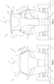
Figure 4 is a front view of the vehicle fromFigures 1 to 3 in the first operating configuration; and -
Figure 5 is a front view of the vehicle inFigures 1 to 4 in the second operating configuration. - In
Figure 1 , the reference number 1 is used to indicate, as a whole, a vehicle for transportingmotor vehicles 100. Preferably and without implying any loss of generality thereby, themotor vehicle 100 is a sports car, for example a vintage car. - In the remainder of this description, the adjectives "front" and "rear" and the related adverbial expressions are to be understood with reference to an advancement direction V of the vehicle 1 or
motor vehicle 100. In addition, the expressions "above" and "below" and the like must be interpreted with reference to the gravity vector g acting on the vehicle 1. - In the embodiment illustrated, the
motor vehicle 100 comprises afront portion 110, arear portion 130, and awindscreen 120 arranged on the front portion 110 (Figure 2 ). However, themotor vehicle 100 could be shaped differently. - As illustrated in
Figure 1 , the vehicle 1 comprises aframe 2 and a plurality ofwheels frame 2 about respective rotational axes A, B, C. - It is possible to define:
- a longitudinal direction X of the vehicle 1;
- a direction Z orthogonal to the direction X and directed vertically to the ground S on which
wheels - a direction Y orthogonal to the directions X and Z.
- The vehicle 1 also comprises a
front end 1a and arear end 1b with respect to the advancement direction V. In addition, thefront end 1a and therear end 1b are arranged opposed to each other along the longitudinal direction X. - With reference to
Figures 1 and 2 , the plurality ofwheels - a pair of
front wheels 3 arranged on thefront end 1a and rotating about the rotational axis A; - a pair of
rear wheels 5 arranged on therear end 1b and rotating about the rotational axis C. - The plurality of
wheels wheels 4 interposed between thefront wheels 3 and therear wheels 5 along the direction X and rotating around the rotational axis B. - In detail, the rotational axes A, B and C are directed transversely to the direction X and are parallel to each other. In addition, the rotational axes A, B and C are spaced apart from each other parallel to the direction X. In further detail, the rotational axis B is closer to the rotational axis C than the rotational axis A along the direction X.
- The
frame 2 includes, in turn, aloading platform 6 adapted to accommodate themotor vehicle 100 and support it during transport. Theloading platform 6 is arranged perpendicular to the direction Z. - In detail, the
loading platform 6 extends along the direction X between the rotational axis A and therear end 1b (Figures 1, 2 and3 ) . - The
frame 2 also comprises acabin 7 designed to accommodate at least one driver of the vehicle 1 and any passengers. - Advantageously, the
cabin 7 includes: - a
portion 7a, which extends between thefront end 1a and theloading platform 6 along the direction X; and - a
portion 7b, which extends cantilevered from theportion 7a at theloading platform 6 along the direction X; thisportion 7b is at least partially spaced apart from theloading platform 6 along the direction Z. - The vehicle 1 also includes a
housing 60 adapted to at least partially house themotor vehicle 100 arranged on theloading platform 6. Thehousing 60 is defined by thecabin 7 and theloading platform 6. - In other words, the
portion 7a is spaced apart from theloading platform 6 along the direction X, theportion 7b is above theloading platform 6, and not in contact with it, and thehousing 60 is arranged below theportion 7b along the direction Z. - In detail, the
portion 7a extends anteriorly to theloading platform 6 along the direction X and theportion 7b faces therear end 1b. (Figures 1, 2 and3 ). In further detail, theportion 7a extends at least between thefront end 1a and the rotational axis A parallel to the direction X. Accordingly, the extension of theportion 7a parallel to the direction X defines the front overhang of the vehicle 1. The extension of theportion 7a parallel to the direction X is preferably between 1/5 and 1/6 of the overall length of the vehicle 1 along the direction X. - The
portion 7b comprises asurface 76 facing theloading platform 6 and is concave in shape. - In detail, proceeding from the
front end 1a towards therear end 1b parallel to the direction X, the distance of the points of thesurface 76 from theloading platform 6 along the direction Z increases progressively (Figure 1 ). - Moreover, the
surface 76 preferably comprises aregion 76a arranged on the side of thefront end 1a and aregion 76b arranged on the side ofrear end 1b. - Considering a plane passing through the directions X and Z, the
region 76a forms angles α1 with theloading platform 6 and theregion 76b forms angles α2 with theloading platform 6; the angles α1 are smaller than the angles α2 (Figure 1 ). - In the embodiment illustrated, the
region 76a is curved; consequently, the angles α1 measured at different points of theregion 76a have different amplitudes. Similarly, theregion 76b is curved; consequently, the angles α2 measured at different points of theregion 76b have different amplitudes. - The
loading platform 6 comprises, in turn: - a region 6a on the side of the
front end 1a, extending below theportion 7b along the direction Z; and - a
region 6b on the side of therear end 1b, which is spaced apart from theportion 7b along the direction X. - In detail, the
housing 60 is defined by theportion 7b and by the region 6a. In further detail, thehousing 60 is delimited at the front by thesurface 76. - Preferably, but not necessarily, the
housing 60 is adapted to house themotor vehicle 100 at thefront portion 110. In detail, theregion 76a is designed to face thefront portion 110 and theregion 76b is designed to face thewindscreen 120. - The
loading platform 6 is arranged at a distance d from the ground S of less than 350 mm (Figure 1 ). In detail, the distance d is less than 350 mm both when amotor vehicle 100 is present on theloading platform 6 and when nopassenger motor vehicle 100 is present on theloading platform 6. The distance d preferably ranges between 200 and 250 mm. In detail, a distance d of between 200 and 250 mm is comparable to the riser of a generic step, for example of a fixed staircase in a building. - The
cabin 7 also comprises: - a
main body 72; - an
opening 73 facing thefront end 1a; and - a
door 74 movably coupled to themain body 72 and adapted to selectively obstruct theopening 73. - The
opening 73 is adapted to allow the driver and any passengers to enter thecabin 7 and exit thecabin 7. - Specifically, the
door 74 also faces thefront end 1a and rotates with respect to themain body 72 between: - a lowered position, in which it closes the opening 73 (
Figures 1 and4 ); and - a raised position, in which it at least partially unblocks the
opening 73 and is spaced apart from it parallel to the direction Z (Figures 2 and5 ). - In the embodiment illustrated, the
door 74 has a curved profile on a plane passing through the directions X and Z (Figures 1 and 2 ). In addition, thedoor 74 includes awindscreen 80 facing thefront end 1a. - In other words, the
door 74 is a canopy type door and the vehicle 1 is a vehicle of the canopy type. - The
cabin 7 also includes afloor 71, which is spaced apart from theloading platform 6 along the direction Z. In particular, thefloor 71 is arranged above theloading platform 6 along the direction Z. - In the embodiment illustrated, the
cabin 7 also includes twoseats 75, respectively for the driver and any passenger and resting on thefloor 71. - The
cabin 7 preferably includes one or twoside doors 77, which can be used for the emergency exit of the driver and/or passengers from thecabin 7. For example, theside doors 77 can be used in the event of a malfunction of thedoor 74. - The
cabin 7 also comprises aladder 30 that is movable with respect to themain body 72 between a retracted position, in which it is in contact with the main body 72 (Figures 1 and4 ), and an extended position (Figure 5 ), in which it projects with respect to themain body 72 from the side opposite therear end 1b (Figure 2 ). - The
ladder 30 is, preferably, automatic. Specifically, the vehicle 1 includes drive means - not illustrated - for automatically moving theladder 30 between the retracted and extended position relative to theframe 2. - The vehicle 1 is preferably an electric or hybrid propulsion vehicle and comprises:
- a plurality of electrical batteries 20 (only a few of which are schematically illustrated in
Figures 1 and 2 ) designed to store electrical energy; and - an electrical motor 21 (only schematically illustrated in
Figures 1 and 2 ) operationally connected to at least some of thewheels electrical batteries 20. - As illustrated in
Figures 1 and 2 , in a known way, theelectrical motor 21 is adapted to transform the electrical energy supplied by theelectrical batteries 20 into mechanical energy and to supply this mechanical energy to the pair offront wheels 3, to which it is operationally connected. Therefore, the pair offront wheels 3 constitutes a pair of drive wheels for the vehicle 1. - In particular, the
electrical batteries 20 are arranged below theloading platform 6 along the direction Z. In other words, theelectrical batteries 20 are designed to be interposed between theloading platform 6 and the ground S along the direction Z. - The vehicle 1 also includes a
ramp 40 that is movable with respect to theframe 2 between a retracted position, in which it is adapted to be spaced apart from the ground S (Figures 1 and3 ) and an extended position, in which it is in contact with the ground S (Figure 2 ). - In the embodiment illustrated, the
ramp 40 is rotatable with respect to theframe 2 between the retracted position and the extended position about a rotational axis perpendicular to the direction X. Specifically, when theramp 40 is in the retracted position, it extends transversely to the loading platform 6 (Figure 1 ); when theramp 40 is in the extended position, it extends cantilevered with respect to theloading platform 6 parallel to the direction X from the opposite side to thefront end 1a (Figure 2 ). - The
ramp 40 preferably comprises a flat or substantiallyflat surface 41 which is adapted to be traversed by themotor vehicle 100 as it is loaded onto theloading platform 6. Thissurface 41 is adapted to face thefront end 1a when theramp 40 is in the retracted position and to face away from the ground S when theramp 40 is in the extended position. - The
ramp 40 is preferably automatic. In detail, the vehicle 1 includes drive means - not illustrated - for automatically moving theramp 40 between the retracted and extended position relative to theframe 2. - Moreover, the total mass of the vehicle 1 when unloaded (that is, when no
motor vehicle 100 lies on the loading platform 6) preferably ranges between 2 and 2.25 tonnes. In addition, the fully loaded mass of the vehicle 1 is less than 4.25 tonnes. - The vehicle 1 may also include securing means - not illustrated - adapted to secure the
motor vehicle 100 to theframe 2. These securing means are adapted to prevent or limit relative sliding between themotor vehicle 100 and theloading platform 6. - The operation of the vehicle 1 according to the invention is described below.
- In use, while the vehicle 1 is stationary in relation to the ground S, the
ramp 40 is moved from the retracted position (Figure 1 ) to the extended position (Figure 2 ) and themotor vehicle 100 is driven onto theloading platform 6 via theramp 40. For example, themotor vehicle 100 is driven by a driver inside themotor vehicle 100. - The
motor vehicle 100 is preferably arranged along theloading platform 6 in such a way that it is accommodated at least partially in thehousing 60. Specifically, thefront end 110 faces theregion 76a and thewindscreen 120 faces theregion 76b. On the other hand, the portion of themotor vehicle 100 not housed in thehousing 60 is arranged at theregion 6b. - Once the
motor vehicle 100 is properly positioned along theloading platform 6, it is secured by the securing means and theramp 40 is returned to the retracted position. The driver of themotor vehicle 100 can therefore descend directly from theloading platform 6, the distance d of which from the ground S is such as to allow easy descent without the need for ladders or similar devices. - The
cabin 7 is accessed by moving thedoor 74 from the lowered to the raised position and theladder 30 from the retracted to the extended position. - After returning the ladder to the retracted position and the
door 74 to the lowered position, the vehicle 1 can move themotor vehicle 100 in relation to the ground S. - From the above, the advantages of the vehicle 1 according to the invention are clear.
- The vehicle 1 comprises the
cabin 7, which is equipped with theportion 7b extending cantilevered from theportion 7a and defining thehousing 60, where themotor vehicle 100 can be accommodated. As a result, themotor vehicle 100 can be at least partially inserted below thecabin 7 and the overall length of the vehicle 1 is reduced. This allows great flexibility and manoeuvrability of the vehicle 1 and solves many of the drawbacks of the known solutions discussed in the introduction to this description. - In addition, the claimed configuration allows both the mass of the vehicle 1 and the
motor vehicle 100 to be mostly concentrated between the rotational axis A of thefront wheels 3 and the rotational axis C of therear wheels 5. This helps to improve the driveability of the vehicle 1 and thus to limit the time needed to transport themotor vehicle 100 using the vehicle 1. - Moreover, due to the fact that the length of the vehicle 1 is less than 7 m, the vehicle 1 is not subject to any particular speed limit.
- Since the
motor vehicle 100 is partially housed in thehousing 6, during the operation of the vehicle 1, themotor vehicle 100 is shielded from thecabin 7. Thus, the vehicle 1 and themotor vehicle 100 constitute a single unit in terms of aerodynamics. - In addition, the claimed shape of the vehicle 1 includes a sufficiently extended front overhang to ensure high energy absorption in favour of the safety of the
cabin 7 occupants and pedestrians. - Since the distance of the points of the
surface 76 from theloading platform 6 along the Z direction increases progressively along the direction X, themotor vehicle 100 can conveniently be made to go inside or come outside thehousing 60 with limited risk of collision and interference. - Since the
surface 76 comprises theregions region 76a is less inclined than theregion 76b with respect to theloading platform 6, theregion 76a is designed to face thefront portion 110 of themotor vehicle 100 and theregion 76b is designed to face thewindscreen 120 of thepassenger motor vehicle 100. - Since the
loading platform 6 is arranged at a distance d from the ground S of less than 350 mm, once themotor vehicle 100 is loaded on theloading platform 6, the driver's descent from thepassenger motor vehicle 100 and thus from theloading platform 6 can be carried out comfortably without the use of additional elements (for example, steps or ladders). - Moreover, the reduced distance d from the ground S makes it possible to limit the distance of the centre of gravity of the vehicle 1 and of the assembly composed of the vehicle 1 and the
motor vehicle 100 lying on theloading platform 6 from the ground S. This makes it possible to considerably increase the driveability of the vehicle 1. - Since the vehicle 1 includes the
front door 74, entering thecabin 7 and exiting thecabin 7 is done from the side opposite theloading platform 6 and is particularly easy and ergonomic. - Since the vehicle 1 is an electric or hybrid vehicle, it is possible to limit the pollutant emissions directly attributable to the use of the vehicle 1 and, thus, to the road transport of the
motor vehicle 100. - Since the vehicle 1 includes the
ramp 40, loading and unloading of themotor vehicle 100 can be done easily, without the need for intervention by specialised operators. - Finally, it is clear that changes may be made to the vehicle 1 according to the invention, and variations produced thereof, that, in any case, do not depart from the scope of protection defined by the claims.
- The vehicle 1 could comprise a single
electrical battery 20 and/or more than oneelectrical motor 21. - The
ramp 40 could slide with respect to theframe 2 between the extended and retracted positions. - The
region 76a could be flat. In this case, the angles α1 measured at different points in theregion 76a would have equal amplitudes. Alternatively or additionally, theregion 76b could be flat. In this case, the angles α2 measured at different points in theregion 76b would have equal amplitudes. - The vehicle 1 may include a different number of
wheels front wheels 3, in particular steering wheels, and the pair ofrear wheels 5 and not include the pair ofwheels 4. In other words, the vehicle 1 could comprise four wheels instead of six. As an alternative or in addition to pair offront wheels 3, the pair ofwheels 4 and/or the pair ofwheels 5 could be drive wheels. In detail, the vehicle 1 might include one or more electrical motors integrated into thewheels 4 or thewheels 5, for example in the corresponding wheel rims.
Claims (10)
- Vehicle (1) for transporting a motor vehicle (100) comprising a frame (2) and a plurality of wheels (3, 4, 5) rotatable relative to said frame (2) about respective rotational axes (A, B, C);said frame (2) comprising, in turn:- a cabin (7) adapted to house at least one driver of the vehicle (1); and- a loading platform (6) adapted to support, in use, said motor vehicle (100) during transport;said vehicle (1) further comprising a front end (1a) and a rear end (1b) opposite to each other along a first advancement direction (V) of said vehicle (1);characterized in that said cabin (7) comprises:- a first portion (7a), which extends between said front end (1a) and said loading platform (6) along a second longitudinal direction (X) of said vehicle (1); and- a second portion (7b), which extends cantilevered from said first portion (7a) at said loading platform (6) along said second direction (X);said second portion (7b) being at least in part spaced apart from said loading platform (6) along a third direction (Z), in use, vertical; said third direction (Z) being orthogonal to said second direction (X);said second portion (7b) and said loading platform (6) defining a housing (60) adapted to house at least in part said motor vehicle (100) supported, in use, by said loading platform (6).
- Vehicle according to claim 1, wherein said second portion (7b) comprises a surface (76) oriented towards the loading platform (6); said surface (76) delimiting said housing (60).
- Vehicle according to claim 2, wherein proceeding from said front end (1a) towards said rear end (1b) parallel to said second longitudinal direction (X), the distance of the points of said surface (76) from said loading platform (6) along said third direction ((Z) progressively increases.
- Vehicle according to claim 2 or 3, wherein said surface (76) comprises:- a first region (76a) arranged on the side of said front end (1a); and- a second region (76b) arranged on the side of said rear end (1b);said first region (76a) forming first angles (α1) with respect to said loading platform (6) in a plane passing through said second and third directions (X, Z);said second region (76b) forming second angles (α2) with respect to said loading platform (6) in a plane passing through said second and third directions (X, Z);said first angles (α1) being smaller than said second angles (α2).
- Vehicle according to any one of the foregoing claims, wherein said cabin (7) comprises:- a main body (72);- an opening (73) facing said front end (1a); and- a door (74) movably coupled to said main body (72) and adapted to selectively obstruct said opening (73).
- Vehicle according to any one of the foregoing claims, characterized in that, in use, the distance (d) between said loading platform (6) and the ground (S) on which said wheels (3, 4, 5) rest, in use, is smaller than 350 mm.
- Vehicle according to any one of the foregoing claims, characterized in that it further comprises:- at least one electrical battery (20) adapted to store, in use, electrical energy;- at least one electrical motor (21) operatively connected to at least one of said wheels (3, 4, 5) and electrically connected to said electrical battery (20).
- Vehicle according to claim 7, characterized in that said at least one electrical battery (20) is arranged beneath said loading platform (6) along said third direction (Z).
- Vehicle according to any one of the foregoing claims, characterized in that the extension thereof along said second direction (X) is smaller than 7 m.
- Vehicle according to any one of the foregoing claims, characterized in that it comprises a ramp (40), which is movable relative to said frame (2) between a retracted position, wherein it is adapted to be spaced away from said ground (S) and an extended position, wherein it is in contact with said ground (S).
Applications Claiming Priority (1)
| Application Number | Priority Date | Filing Date | Title |
|---|---|---|---|
| IT102023000026643A IT202300026643A1 (en) | 2023-12-14 | 2023-12-14 | VEHICLE FOR THE TRANSPORT OF CARS |
Publications (1)
| Publication Number | Publication Date |
|---|---|
| EP4570591A1 true EP4570591A1 (en) | 2025-06-18 |
Family
ID=89897145
Family Applications (1)
| Application Number | Title | Priority Date | Filing Date |
|---|---|---|---|
| EP24219287.0A Pending EP4570591A1 (en) | 2023-12-14 | 2024-12-12 | Vehicle for transporting motor vehicles |
Country Status (3)
| Country | Link |
|---|---|
| US (1) | US20250196752A1 (en) |
| EP (1) | EP4570591A1 (en) |
| IT (1) | IT202300026643A1 (en) |
Citations (3)
| Publication number | Priority date | Publication date | Assignee | Title |
|---|---|---|---|---|
| JP2018043563A (en) * | 2016-09-13 | 2018-03-22 | 株式会社ホンダアクセス | Back panel and load-carrying platform structure |
| EP3459788A1 (en) * | 2017-09-22 | 2019-03-27 | McGee, Mike | Autonomous driving vehicle for transporting occupied non autonomous powered vehicles |
| WO2023139837A1 (en) * | 2022-01-20 | 2023-07-27 | いすゞ自動車株式会社 | Vehicle cab rear structure |
-
2023
- 2023-12-14 IT IT102023000026643A patent/IT202300026643A1/en unknown
-
2024
- 2024-12-12 EP EP24219287.0A patent/EP4570591A1/en active Pending
- 2024-12-13 US US18/980,182 patent/US20250196752A1/en active Pending
Patent Citations (3)
| Publication number | Priority date | Publication date | Assignee | Title |
|---|---|---|---|---|
| JP2018043563A (en) * | 2016-09-13 | 2018-03-22 | 株式会社ホンダアクセス | Back panel and load-carrying platform structure |
| EP3459788A1 (en) * | 2017-09-22 | 2019-03-27 | McGee, Mike | Autonomous driving vehicle for transporting occupied non autonomous powered vehicles |
| WO2023139837A1 (en) * | 2022-01-20 | 2023-07-27 | いすゞ自動車株式会社 | Vehicle cab rear structure |
Also Published As
| Publication number | Publication date |
|---|---|
| US20250196752A1 (en) | 2025-06-19 |
| IT202300026643A1 (en) | 2025-06-14 |
Similar Documents
| Publication | Publication Date | Title |
|---|---|---|
| US11472464B2 (en) | Body mounted sliding steering column with offset feedback actuator | |
| US10457314B2 (en) | Retractable telescopic mechanism for steering column with feedback actuator | |
| CN104395183B (en) | small vehicle | |
| US4585273A (en) | Vehicle seat | |
| US3060471A (en) | Aero-gangplank | |
| US5618151A (en) | Street vehicle for passenger and cargo transport facilitating loading and discharge | |
| US11148738B2 (en) | Vehicle | |
| CN114469545B (en) | Vehicle entry and exit auxiliary structure | |
| CN111823973A (en) | Mobile transporters with vehicle seats and vehicles with mobile transporters | |
| EP4570591A1 (en) | Vehicle for transporting motor vehicles | |
| US10632962B2 (en) | Seatbelt retractor | |
| US20230286586A1 (en) | Expanding length vehicle chassis | |
| WO2002053454A1 (en) | Vehicle for transportation of passengers in airport | |
| US6557926B1 (en) | Motor vehicle with a load-space securing element | |
| CN117818453A (en) | Control method and device for aerocar and related equipment | |
| KR20250067087A (en) | Vehicles for ride sharing and package delivery services and how to use them | |
| GB2417021A (en) | Passenger service vehicle disabled persons lift | |
| KR20190007594A (en) | Carriage for Transporting Cars | |
| RU217545U1 (en) | Car for people with disabilities and people with limited mobility | |
| CN119329643B (en) | Transportation means | |
| CN119774031B (en) | Unmanned aerial vehicle (UAV) take-off and landing equipment, UAV take-off and landing systems and vehicles | |
| ITTO20000825A1 (en) | SMALL SIZE CAR, ESPECIALLY FOR URBAN TRANSPORT, WITH FRONT DOOR. | |
| US12319178B2 (en) | Elevated vehicle system | |
| EP2201920B1 (en) | Transportation vehicle provided with access means for persons with reduced mobility | |
| JPH0726197Y2 (en) | Car-only car |
Legal Events
| Date | Code | Title | Description |
|---|---|---|---|
| PUAI | Public reference made under article 153(3) epc to a published international application that has entered the european phase |
Free format text: ORIGINAL CODE: 0009012 |
|
| STAA | Information on the status of an ep patent application or granted ep patent |
Free format text: STATUS: THE APPLICATION HAS BEEN PUBLISHED |
|
| AK | Designated contracting states |
Kind code of ref document: A1 Designated state(s): AL AT BE BG CH CY CZ DE DK EE ES FI FR GB GR HR HU IE IS IT LI LT LU LV MC ME MK MT NL NO PL PT RO RS SE SI SK SM TR |
|
| STAA | Information on the status of an ep patent application or granted ep patent |
Free format text: STATUS: REQUEST FOR EXAMINATION WAS MADE |
|
| 17P | Request for examination filed |
Effective date: 20251217 |