EP4568366A1 - Verfahren zum senden eines sidelink (sl)-positionierungsreferenzsignals (prs) und vorrichtung - Google Patents
Verfahren zum senden eines sidelink (sl)-positionierungsreferenzsignals (prs) und vorrichtung Download PDFInfo
- Publication number
- EP4568366A1 EP4568366A1 EP22953604.0A EP22953604A EP4568366A1 EP 4568366 A1 EP4568366 A1 EP 4568366A1 EP 22953604 A EP22953604 A EP 22953604A EP 4568366 A1 EP4568366 A1 EP 4568366A1
- Authority
- EP
- European Patent Office
- Prior art keywords
- prs
- path loss
- terminal device
- transmission power
- link
- Prior art date
- Legal status (The legal status is an assumption and is not a legal conclusion. Google has not performed a legal analysis and makes no representation as to the accuracy of the status listed.)
- Pending
Links
Images


Classifications
-
- H—ELECTRICITY
- H04—ELECTRIC COMMUNICATION TECHNIQUE
- H04W—WIRELESS COMMUNICATION NETWORKS
- H04W64/00—Locating users or terminals or network equipment for network management purposes, e.g. mobility management
-
- H—ELECTRICITY
- H04—ELECTRIC COMMUNICATION TECHNIQUE
- H04B—TRANSMISSION
- H04B17/00—Monitoring; Testing
- H04B17/30—Monitoring; Testing of propagation channels
- H04B17/309—Measuring or estimating channel quality parameters
- H04B17/318—Received signal strength
- H04B17/328—Reference signal received power [RSRP]; Reference signal received quality [RSRQ]
-
- H—ELECTRICITY
- H04—ELECTRIC COMMUNICATION TECHNIQUE
- H04W—WIRELESS COMMUNICATION NETWORKS
- H04W4/00—Services specially adapted for wireless communication networks; Facilities therefor
- H04W4/30—Services specially adapted for particular environments, situations or purposes
- H04W4/40—Services specially adapted for particular environments, situations or purposes for vehicles, e.g. vehicle-to-pedestrians [V2P]
-
- H—ELECTRICITY
- H04—ELECTRIC COMMUNICATION TECHNIQUE
- H04W—WIRELESS COMMUNICATION NETWORKS
- H04W52/00—Power management, e.g. Transmission Power Control [TPC] or power classes
- H04W52/04—Transmission power control [TPC]
- H04W52/18—TPC being performed according to specific parameters
- H04W52/24—TPC being performed according to specific parameters using SIR [Signal to Interference Ratio] or other wireless path parameters
- H04W52/242—TPC being performed according to specific parameters using SIR [Signal to Interference Ratio] or other wireless path parameters taking into account path loss
-
- H—ELECTRICITY
- H04—ELECTRIC COMMUNICATION TECHNIQUE
- H04W—WIRELESS COMMUNICATION NETWORKS
- H04W52/00—Power management, e.g. Transmission Power Control [TPC] or power classes
- H04W52/04—Transmission power control [TPC]
- H04W52/30—Transmission power control [TPC] using constraints in the total amount of available transmission power
- H04W52/32—TPC of broadcast or control channels
- H04W52/325—Power control of control or pilot channels
-
- H—ELECTRICITY
- H04—ELECTRIC COMMUNICATION TECHNIQUE
- H04W—WIRELESS COMMUNICATION NETWORKS
- H04W52/00—Power management, e.g. Transmission Power Control [TPC] or power classes
- H04W52/04—Transmission power control [TPC]
- H04W52/38—TPC being performed in particular situations
- H04W52/383—TPC being performed in particular situations power control in peer-to-peer links
-
- H—ELECTRICITY
- H04—ELECTRIC COMMUNICATION TECHNIQUE
- H04W—WIRELESS COMMUNICATION NETWORKS
- H04W72/00—Local resource management
- H04W72/20—Control channels or signalling for resource management
- H04W72/25—Control channels or signalling for resource management between terminals via a wireless link, e.g. sidelink
-
- H—ELECTRICITY
- H04—ELECTRIC COMMUNICATION TECHNIQUE
- H04W—WIRELESS COMMUNICATION NETWORKS
- H04W4/00—Services specially adapted for wireless communication networks; Facilities therefor
- H04W4/70—Services for machine-to-machine communication [M2M] or machine type communication [MTC]
-
- H—ELECTRICITY
- H04—ELECTRIC COMMUNICATION TECHNIQUE
- H04W—WIRELESS COMMUNICATION NETWORKS
- H04W88/00—Devices specially adapted for wireless communication networks, e.g. terminals, base stations or access point devices
- H04W88/18—Service support devices; Network management devices
-
- H—ELECTRICITY
- H04—ELECTRIC COMMUNICATION TECHNIQUE
- H04W—WIRELESS COMMUNICATION NETWORKS
- H04W92/00—Interfaces specially adapted for wireless communication networks
- H04W92/16—Interfaces between hierarchically similar devices
- H04W92/18—Interfaces between hierarchically similar devices between terminal devices
Definitions
- the present disclosure relates to the field of communication technologies, and in particular to a method and an apparatus for transmitting a sidelink (SL) positioning reference signal (PRS).
- SL sidelink
- PRS positioning reference signal
- a terminal device can perform positioning by transmitting a sidelink (SL) positioning reference signal (PRS).
- the SL PRS transmitted by the terminal device may need to be received by multiple positioning auxiliary devices, and method of determining the transmission power of the SL PRS needs to be specified.
- Embodiments of the present disclosure provide a method and an apparatus for transmitting a sidelink (SL) positioning reference signal (PRS).
- a transmission power of the SL PRS is determined according to a path loss of a transmission path, and the SL PRS is transmitted, ensuring that all positioning auxiliary devices can receive the SL PRS, achieving accurate and reliable positioning of a terminal device.
- SL sidelink
- PRS positioning reference signal
- an embodiment of the present disclosure provides a method for transmitting a sidelink (SL) positioning reference signal (PRS).
- the method is performed by a first terminal device.
- the method includes: determining a transmission power of the SL PRS according to a path loss of a transmission path; and transmitting the SL PRS according to the transmission power.
- SL sidelink
- PRS positioning reference signal
- the first terminal device determines the transmission power of the SL PRS according to the path loss of the transmission path, and then transmits the SL PRS, thereby ensuring that each of multiple positioning auxiliary devices can receive the SL PRS, and achieving accurate and reliable positioning of the terminal device.
- an embodiment of the present disclosure provides a communication device, which includes:
- an embodiment of the present disclosure provides a communication device.
- the communication device includes a processor.
- the processor executes the method described in the first aspect.
- an embodiment of the present disclosure provides a communication device.
- the communication device includes a processor and a memory, and a computer program is stored in the memory.
- the processor is configured to execute the computer program stored in the memory to cause the communication device to execute the method described in the above first aspect.
- an embodiment of the present disclosure provides a communication device.
- the device includes a processor and an interface circuit.
- the interface circuit is configured to receive code instructions and transmit them to the processor.
- the processor is configured to execute the code instructions to cause the device to execute the method described in the above first aspect.
- an embodiment of the present disclosure provides a communication system.
- the system includes the communication device described in the second aspect, or the system includes the communication device described in the third aspect, or the system includes the communication device described in the fourth aspect, or the system includes the communication device described in the fifth aspect.
- an embodiment of the present disclosure provides a computer-readable storage medium, configured to store instructions used by the terminal device. The instructions, when executed, cause the terminal device to execute the method described in the first aspect.
- the present disclosure also provides a computer program product, including a computer program, which, when running on a computer, causes the computer to execute the method described in any one of the above first aspect.
- the present disclosure provides a chip system.
- the chip system includes at least one processor and an interface for supporting the first terminal device to implement the functions involved in the first aspect, for example, determining or processing at least one of data or information involved in the above method.
- the chip system further includes a memory, and the memory is configured to store necessary computer programs and data for the terminal device.
- the chip system may be composed of chips, or may include a chip and other discrete devices.
- the present disclosure provides a computer program that, when running on a computer, causes the computer to perform the method described in any one of the above first aspect.
- FIG. 1 is a schematic architectural diagram of a communication system provided by an embodiment of the present disclosure, a terminal device 11 can determine a specific position of the terminal device relative to the RSU by measuring PRS transmitted by multiple (greater than or equal to 3) positioning auxiliary devices (RSU) through SL links.
- RSU road side unit
- a positioning result is not converted into absolute position coordinates according to absolute position information such as GPS of RSU, the positioning result is relative positioning; otherwise, it is absolute positioning.
- the RSU that participates in relative positioning or absolute positioning is a positioning auxiliary device.
- the terminal device may also be used as a positioning auxiliary device, and it is difficult for the terminal device to assist in providing positioning services together with other UEs.
- some positioning auxiliary devices can obtain position information through global positioning system (GPS) and the like, which can assist other terminal devices in absolute positioning.
- GPS global positioning system
- the communication system may include, but not limited to, one terminal device and one positioning auxiliary device.
- the number and the form of devices shown in FIG. 1 are only for examples and do not constitute a limitation onto the embodiments of the present disclosure. In actual applications, the system may include two or more terminal devices, and two or more positioning auxiliary devices.
- the communication system shown in FIG. 1 includes one terminal device 11 and three positioning auxiliary devices 12, 13 and 14, which is taken as an example.
- LTE long term evolved
- 5G 5th generation
- NR 5th generation new radio
- the terminal device 11 in the embodiments of the present disclosure may be an entity on the user side for receiving or transmitting signals, such as a mobile phone.
- the terminal device may also be referred to as terminal, user equipment (UE), mobile station (MS), mobile terminal (MT), etc.
- the terminal device may be a car with communication functions, a smart car, a mobile phone, a wearable device, a tablet computer (Pad), a computer with wireless transceiver functions, a virtual reality (VR) terminal device, an augmented reality (AR) terminal device, a wireless terminal device in industrial control, a wireless terminal device in self-driving, a wireless terminal device in remote medical surgery, a wireless terminal device in a smart grid, a wireless terminal device in transportation safety, a wireless terminal device in smart city, a wireless terminal device in smart home, etc.
- the specific technique and the specific device form used by the terminal device are not limited in the embodiments of the present disclosure.
- the positioning auxiliary device in the embodiments of the present disclosure may be an entity for transmitting or receiving signals.
- the positioning auxiliary device may be an RSU, or the positioning auxiliary device may also be a terminal device, or the positioning auxiliary device may also be an evolved NodeB (eNB), a transmission reception point (TRP), a next generation NodeB (gNB) in an NR system, a base station in other future mobile communication systems, an access node in a wireless fidelity (WiFi) system, or the like.
- eNB evolved NodeB
- TRP transmission reception point
- gNB next generation NodeB
- WiFi wireless fidelity
- the terminal device may implement the method shown in any of embodiments of FIG. 2 to FIG. 7 of the present disclosure.
- the present disclosure mainly focuses on the problem of how to accurately determine a transmission power of an SL PRS in an SL link positioning process where the SL PRS transmitted by the terminal device may need to be received by multiple positioning auxiliary devices. It is proposed to determine the transmission power of the SL PRS according to an actual path loss, and then transmit the SL PRS according to the determined transmission power, which ensures that each of the positioning auxiliary devices can receive the SL PRS, thereby achieving accurate and reliable positioning on the terminal device.
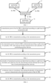
- FIG. 2 is a schematic flowchart of a method for transmitting a sidelink (SL) positioning reference signal (PRS) provided by an embodiment of the present disclosure.
- the method is performed by a first terminal device.
- the method may include, but not limited to, the following steps.
- a transmission power of an SL PRS is determined according to a path loss of a transmission path.
- the path loss of the transmission path includes a path loss of a downlink and/or a path loss of an SL link.
- the path loss of the downlink is a path loss of an air interface between a terminal device and a network device, and may also be referred to as a path loss of a Uu interface.
- the path loss of the Uu port may be calculated and determined by the terminal device according to an RSRP value of a received downlink signal and a transmission power value of the network device, which is not limited by the present disclosure.
- the first terminal device may determine the transmission power of the SL PRS according to the path loss of the downlink.
- the terminal device may determine the path loss of the Uu port as the path loss of the transmission path, or may also determine the path loss of the SL link as the path loss of the transmission path, or may also select one from the path loss of the Uu port and the path loss of the SL link as the path loss of the transmission path according to a rule, or may also determine the path loss of the transmission path according to a combination of the path loss of the Uu port and the path loss of the SL link according to a rule, which is not limited by the present disclosure.
- the terminal device may determine the path loss of the SL link according to a reference signal received power (RSRP) value of a demodulation reference signal (DMRS) of a physical SL shared channel (physical sidelink control channel, PSSCH) or a physical SL control channel (physical sidelink control channel, PSCCH).
- RSRP reference signal received power
- DMRS demodulation reference signal
- a terminal device B receives a DMRS in a PSSCH transmitted by a terminal device A (the first terminal device) to calculate an SL RSRP, performs layer 3 filtering on the SL RSRP and transmits it to the terminal device A.
- the terminal device A may obtain the path loss of the SL link by subtracting the SL RSRP from the transmission power of the PSSCH.
- the terminal device A may further transmit the obtained path loss of the SL link to the terminal device B. That is to say, the terminal device may determine the path loss of the SL link by itself, or may receive the path loss of the SL link transmitted by another terminal device.
- the terminal device may also determine the path loss of the SL link according to a RSRP value of the SL PRS.
- the terminal device may also determine the path loss of the SL link according to a DMRS of an SL synchronization signal block (SSB).
- the terminal device may also determine the path loss of the SL link according to a primary synchronization signal (PSS) of an SL SSB.
- the terminal device may also determine the path loss of the SL link according to a secondary synchronization signal (SSS) of an SL SSB.
- PSS primary synchronization signal
- SSS secondary synchronization signal
- the terminal device B receives the SL PRS transmitted by the terminal device A (the first terminal device), calculates the SL RSRP, then performs layer 3 filtering on the SL RSRP and transmits it to the terminal device A.
- the terminal device A may obtain a path loss of an SL link between the terminal device A and the terminal device B after subtracting the SL RSRP from the transmission power of the PSSCH, and may further transmit the path loss of the SL link between the terminal device A and the terminal device B to the terminal device B.
- step 202 the SL PRS is transmitted according to the transmission power.
- the first terminal device may transmit the SL PRS according to the transmission power, thereby ensuring that the positioning auxiliary device can receive the PRS, so as to achieve positioning of the terminal device.
- the first terminal device may transmit the SL PRS at a determined transmission power, or may transmit the SL PRS at a power value not lower than a determined transmission power, which is not limited in the present disclosure.
- the first terminal device first determines the transmission power of the SL PRS according to the path loss of the transmission path, and then transmits the SL PRS according to the determined transmission power, which ensures that multiple positioning auxiliary devices can receive the SL PRS, thereby achieving accurate and reliable positioning of the terminal device.
- FIG. 3 is a schematic flowchart of another method for transmitting a sidelink (SL) positioning reference signal (PRS) provided by an embodiment of the present disclosure.
- the method is performed by a first terminal device.
- the method may include, but not limited to, the following steps.
- step 301 the transmission power of the SL PRS is determined according to path losses of a plurality of SL links between the first terminal device and a plurality of positioning auxiliary devices.
- the plurality of positioning auxiliary devices are devices that receive the SL PRS transmitted by the first terminal device.
- the plurality of positioning auxiliary devices may be other terminal devices or RSUs, which is not limited in the present disclosure.
- a terminal device A may determine how many positioning auxiliary devices need to receive the SL PRS transmitted by the terminal device A according to a previous positioning negotiation process. For example, for positioning of SL time difference of arrival (TDOA), positioning of angle of arrival (AOA), and positioning of angle of departure (AOD), the terminal device A transmits SL PRS signals to multiple positioning auxiliary devices (usually greater than or equal to 3), and the multiple positioning auxiliary devices calculate the time of arrival, or the angle of arrival, or the RSRP of the SL PRS respectively, and finally calculate a position of UE A according to the results.
- TDOA time difference of arrival
- AOA positioning of angle of arrival
- AOD positioning of angle of departure
- the first terminal device may determine a minimum value among a plurality of transmission powers respectively determined according to the path losses of the plurality of SL links as the transmission power of the SL PRS; or may determine a maximum value among a plurality of transmission powers respectively determined according to the path losses of the plurality of SL links as the transmission power of the SL PRS.
- the terminal device A there are three positioning auxiliary devices that receive the SL PRS transmitted by the first terminal device (the terminal device A), which are a terminal device B, a terminal device C, and a terminal device D.
- the terminal device A determines a transmission power value as P1 according to a path loss of an SL link between the terminal device A and the terminal device B, determines a transmission power value as P2 according to a path loss of an SL link between the terminal device A and the terminal device C, and determines a transmission power value as P3 according to a path loss of an SL link between the terminal device A and the terminal device D, where P1 ⁇ P2 ⁇ P3.
- the terminal device may determine P1 as the transmission power of the SL PRS, or may determine P3 as the transmission power of the SL PRS, which is not limited in the present disclosure.
- the first terminal device may determine a path loss value corresponding to the first terminal device according to the path losses of the plurality of SL links and a weight value corresponding to each of the SL links, and may determine the transmission power of the SL PRS according to the path loss value.
- the path loss of the SL link between the terminal device A and the terminal device B is S1 with a corresponding weight value a
- the path loss of the SL link between the terminal device A and the terminal device C is S2 with a corresponding weight value b
- the path loss of the SL link between the terminal device A and the terminal device D is S3 with a corresponding weight value c
- a weight value corresponding to each SL link may be configured by a network device, or determined by the first terminal device according to a type of the positioning auxiliary device, etc., which is not limited in the present disclosure.
- step 302 the SL PRS is transmitted according to the transmission power.
- the first terminal device determines the transmission power of the SL PRS according to the path losses of the SL links with multiple positioning auxiliary devices, and then transmits the SL PRS according to the determined transmission power, which ensures that each positioning auxiliary device can receive the SL PRS, thereby achieving accurate and reliable positioning of the terminal device.
- FIG. 4 is a schematic flowchart of another method for transmitting a sidelink (SL) positioning reference signal (PRS) provided by an embodiment of the present disclosure.
- the method is performed by a first terminal device.
- the method may include, but not limited to, the following steps.
- a plurality of transmission powers are determined according to a path loss of a downlink and a path loss of an SL link between the first terminal device and one or more positioning auxiliary devices.
- the first terminal device may determine one transmission power according to the path loss of the downlink, and may determine one or more transmission powers according to the path loss of the SL link between the first terminal device and one or more positioning auxiliary devices, that is, the first terminal may determine the plurality of transmission powers.
- step 402 a minimum value or a maximum value among the plurality of transmission powers is determined as the transmission power of the SL PRS.
- the first terminal device determines a transmission power according to the path loss of the downlink as P1, determines a transmission power according to a path loss of an SL link between the first terminal device and a positioning auxiliary device 1 as P2, determines a transmission power according to a path loss of an SL link between the first terminal device and a positioning auxiliary device 2 as P3, and determines a transmission power according to a path loss of an SL link between the first terminal device and a positioning auxiliary device 3 as P4, where P1>P2>P3>P4. Then, the first terminal device may determine P1 as the transmission power of the SL PRS, or may determine P4 as the transmission power of the SL PRS.
- the first terminal device determines the transmission power according to the path loss of the downlink as P1, determines a path loss of the SL link between the first terminal device and the positioning auxiliary device 1 being S1 and a corresponding weight being a, determines a path loss of the SL link between the first terminal device and the positioning auxiliary device 2 being S2 and a corresponding weight being b, and determines a path loss of the SL link between the first terminal device and the positioning auxiliary device 3 being S3 and a corresponding weight being c.
- the first terminal device determines a total path loss S according to a path loss of each SL link and a weight of each SL link, and further determines a transmission power as P2, where P1 ⁇ P2.
- the first terminal device may determine P1 as the transmission power of the SL PRS, or determine P2 as the transmission power of the SL PRS, which is not limited in the present disclosure.
- step 403 the SL PRS is transmitted according to the transmission power.
- the first terminal device may determine the plurality of transmission powers according to the path loss of the downlink and the path loss of the SL link between the first terminal device and one or more positioning auxiliary devices, then may determine a minimum value or a maximum value among the plurality of transmission powers as the transmission power of the SL PRS, and may transmit the SL PRS according to the determined transmission power. In this way, it ensures that multiple positioning auxiliary devices can receive the SL PRS, thereby achieving accurate and reliable positioning of the terminal device.
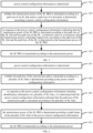
- FIG. 5 is a schematic flowchart of another method for transmitting a sidelink (SL) positioning reference signal (PRS) provided by an embodiment of the present disclosure.
- the method is performed by a first terminal device.
- the method may include, but not limited to, the following steps.
- step 501 power control configuration information is determined.
- the power control configuration information may be used to instruct the first terminal device a manner of calculating the SL PRS transmission power.
- the power control configuration information may be preset in the first terminal device, which is not limited in the present disclosure.
- the first terminal device may also receive the power control configuration information transmitted by a second terminal device.
- the first terminal device may receive the power control configuration information transmitted by the second terminal device in any of the following manners: an SL long term evolved positioning protocol (LPP) message, a PC5-S message, a radio resource control (RRC) message, or SL control information (SCI).
- LPP long term evolved positioning protocol
- PC5-S PC5-S message
- RRC radio resource control
- SCI SL control information
- the first terminal device may receive the power control configuration information transmitted by a network device.
- the first terminal device may receive the power control configuration information transmitted by the network device via an LPP message.
- the first terminal device may receive the power control configuration information transmitted by a location management function (LMF) device.
- LMF location management function
- the first terminal device receives the power control configuration information transmitted by the LMF in any of the following manners: a system broadcast message, a radio resource control (RRC) reconfiguration message, an RRC release message, downlink control information (DCI), or a medium access control (MAC) control element (CE).
- RRC radio resource control
- DCI downlink control information
- CE medium access control control element
- step 502 whether the transmission power of the SL PRS is calculated according to a path loss of an SL link and/or a path loss of a downlink is determined according to power control configuration information.
- the power control configuration information may instruct the first terminal device to calculate the transmission power of the SL PRS according to a path loss of one SL link; or may instruct the first terminal device to calculate the transmission power of the SL PRS according to path losses of multiple SL links; or instruct the first terminal device to calculate the transmission power of the SL PRS according to the path loss of the downlink; or instruct the first terminal device to calculate the transmission power of the SL PRS according to the path loss of the SL link and the path loss of the downlink, etc., which is not limited in the present disclosure.
- step 503 in response to the power control configuration information indicating that the transmission power of the SL PRS is calculated according to the path loss of the SL link and the path loss of the DL, a minimum value or a maximum value of transmission powers calculated respectively according to the path loss of the SL link and the path loss of the DL is determined as the transmission power of the SL PRS.
- the first terminal device may calculate a transmission power of one SL PRS according to the path loss of the downlink, may calculate a transmission power of one or more SL PRSs according to a path loss of one or more SL links, and may determine a minimum value or a maximum value among the multiple calculated transmission powers as the transmission power of the SL PRS.
- step 504 the SL PRS is transmitted according to the transmission power.
- the first terminal device determines the power control configuration information, and when the power control configuration information indicates that the transmission power of the SL PRS is calculated according to the path loss of the SL link and the path loss of the downlink, the first terminal device may determine a minimum value or a maximum value of transmission powers calculated according to the path loss of the SL link and the path loss of the DL as the transmission power of the SL PRS, and may transmit the SL PRS according to the determined transmission power. Therefore, it ensures that each of the positioning auxiliary devices can receive the SL PRS, thereby achieving accurate and reliable positioning of the terminal device.
- FIG. 6 is a schematic flowchart of another method for transmitting a sidelink (SL) positioning reference signal (PRS) according to an embodiment of the present disclosure.
- the method is performed by a first terminal device.
- the method may include, but not limited to, the following steps.
- step 601 power control configuration information is determined.
- step 601 and step 602 reference can be made to the detailed description of any embodiment of the present disclosure, which will not be described again here.
- step 602 whether the path loss of the transmission path is calculated according to a plurality of SL links is determined according to the power control configuration information.
- the power control configuration information may include an information field dedicated for indicating whether to calculate the path loss of the transmission path according to a plurality of SL links, so that the first terminal device may determine whether to calculate the path loss according to a plurality of SL links based on a value of the information field. For example, if the value of the information field is 1, it indicates that the path loss is calculated according to a plurality of SL links, otherwise, it indicates that the path loss is not calculated according to a plurality of SL links, etc., which is not limited in the present disclosure.
- the first terminal device may also determine whether the transmission path can be calculated according to a plurality of SL links according to the number of identification information of the SL links included in the power control configuration information.
- the first terminal device may determine that the power control configuration information indicates that the path loss is calculated according to the plurality of SL links; if identification information of only one SL link is included, it indicates that the path loss is calculated according to the one SL link, etc., and the present disclosure does not limit thereto.
- the identification information of the SL link may be a layer 2 source identification (SL layer 2 source ID) and/or an SL layer 2 destination ID.
- step 603 in response to the power control configuration information including identification information of a plurality of SL links, it is determined that the power control configuration information indicates that the path loss of the transmission path is calculated according to the plurality of SL links.
- the first terminal device may determine that the power control configuration information indicates that the path loss of the transmission path is calculated according to the plurality of SL links.
- step 604 the transmission power of the SL PRS is determined according to path losses of the plurality of SL links in the power control configuration information.
- step 605 the SL PRS is transmitted according to the transmission power.
- the first terminal device determines the power control configuration information, and when the power control configuration information indicates that the transmission power of the SL PRS is calculated according to path losses of a plurality of SL links, the first terminal device calculates the transmission power of the SL PRS according to the path losses of the plurality of SL links, and transmits the SL PRS according to the determined transmission power, which ensures that each of the positioning auxiliary devices can receive the SL PRS, thereby achieving accurate and reliable positioning of the terminal device.
- FIG. 7 is a schematic flowchart of another method for transmitting a sidelink (SL) positioning reference signal (PRS) according to an embodiment of the present disclosure.
- the method is performed by a first terminal device.
- the method may include, but not limited to, the following steps.
- step 701 power control configuration information is determined.
- step 701 For the specific implementation of the above step 701, reference can be made to the detailed description of any embodiment of the present disclosure, which will not be described again here.
- step 702 in response to the power control configuration information including the identification information of one SL link, it is determined that the power control configuration information indicates that the path loss of the transmission path is not calculated according to the plurality of SL links.
- step 703 the transmission power of the SL PRS is determined according to a path loss of the one SL link in the power control configuration information.
- the first terminal device may calculate the transmission power of the SL PRS according to the path loss of the one SL link.
- step 704 the SL PRS is transmitted according to the transmission power.
- the first terminal device determines the power control configuration information, and when the power control configuration information only includes identification information of one SL link, the first terminal device may calculate the transmission power of the SL PRS according to the path loss of the one SL link, and then may transmit the SL PRS according to the determined transmission power, which ensures that each of the positioning auxiliary devices can receive the SL PRS, thereby achieving accurate and reliable positioning of the terminal device.
- FIG. 8 is a schematic flowchart of another method for transmitting a sidelink (SL) positioning reference signal (PRS) according to an embodiment of the present disclosure.
- the method is performed by a first terminal device.
- the method may include, but not limited to, the following steps.
- step 801 power control configuration information is determined.
- step 802 in response to the power control configuration information indicating that the path loss of the transmission path is not calculated according to a plurality of SL links and including identification information of the plurality of SL links, the transmission power of the SL PRS is determined according to a path loss of one SL link among the plurality of SL links.
- the power control configuration information includes an information field specifically used to indicate whether to calculate the path loss according to a plurality of SL links.
- the first terminal device may first determine whether to calculate the path loss according to the plurality of SL links according to a value of the information field.
- the first terminal device determines the transmission power of the SL PRS according to a path loss of one SL link among the plurality of SL links.
- the first terminal device may calculate the path loss of the transmission path according to any one SL link among the plurality of SL links.
- the first terminal device may calculate the path loss of the transmission path according to a designated SL link among the multiple SL links.
- the designated SL link is a link between the first terminal device and a designated positioning auxiliary device
- the designated positioning auxiliary device is a device that receives the SL PRS and has only an SL unicast connection with the first terminal device.
- the first terminal device may first determine a positioning auxiliary device corresponding to identification information of each SL link, and then may determine the number and the types of links between the first terminal device and each positioning auxiliary device. If the first terminal device has only an SL unicast connection with a certain positioning auxiliary device, the certain positioning auxiliary device may be determined as the designated positioning auxiliary device, and the transmission power of the SL PRS is calculated according to a path loss of an SL link between the first terminal device and the designated positioning auxiliary device.
- the first terminal device may determine the transmission power of the SL PRS according to a path loss of the one SL link.
- step 803 the SL PRS is transmitted according to the transmission power.
- the first terminal device first determines the power control configuration information, and when the power control configuration information indicates that the path loss of the transmission path is not calculated according to a plurality of SL links, and the power control configuration information includes identification information of the plurality of SL links, the first terminal device may determine the transmission power of the SL PRS according to the path loss of one SL link among the plurality of SL links, and may transmit the SL PRS according to the determined transmission power, which ensures that each positioning auxiliary device can receive SL PRS, thereby achieving accurate and reliable positioning of the terminal device.
- FIG. 9 is a schematic structural diagram of a communication device provided by an embodiment of the present disclosure.
- the communication device 900 shown in FIG. 9 may include a processing module 901 and a transceiver module 902.
- the transceiver module 902 may include a transmitting module and/or a receiving module.
- the transmitting module is configured to implement a transmitting function
- the receiving module is configured to implement a receiving function.
- the transceiver module 902 may implement the transmitting function and/or the receiving function.
- the communication device 900 may be a first terminal device, a device in the first terminal device, or a device that may be used in conjunction with the first terminal device.
- the communication device 900 is on the side of the first terminal device.
- the processing module 901 is configured to determine a transmission power of an SL PRS according to a path loss of a transmission path.
- the transceiver module 902 is configured to transmit the SL PRS according to the transmission power.
- the path loss of the transmission path includes a path loss of a downlink or a path loss of an SL link.
- processing module 901 is configured to:
- the processing module 901 is further configured to determine the transmission power of the SL PRS according to path losses of a plurality of SL links between the first terminal device and a plurality of positioning auxiliary devices.
- the plurality of positioning auxiliary devices are devices that receive the SL PRS transmitted by the first terminal device.
- processing module 901 is further configured to:
- processing module 901 is further configured to:
- processing module 901 is further configured to:
- processing module 901 is further configured to:
- the processing module 901 is further configured to: in response to the power control configuration information indicating that the transmission power of the SL PRS is calculated according to the path loss of the SL link and the path loss of the DL, determine a minimum value or a maximum value of transmission powers calculated respectively according to the path loss of the SL link and the path loss of the DL as the transmission power of the SL PRS.
- the processing module 901 is further configured to: determine, according to power control configuration information, whether the path loss of the transmission path is calculated according to a plurality of SL links.
- processing module 901 is further configured to:
- processing module 901 is further configured to:
- processing module 901 is further configured to:
- the transceiver module 902 is further configured to:
- the transceiver module 902 is further configured to:
- the transceiver module 902 is further configured to: receive the power control configuration information transmitted by the network device via an LPP message.
- the transceiver module 902 is further configured to:
- the first terminal device determines the transmission power of the SL PRS according to the path loss of the transmission path, and then transmits the SL PRS according to the determined transmission power. This ensures that each positioning auxiliary device can receive SL PRS, thereby achieving accurate and reliable positioning of the terminal device.
- FIG. 10 is a schematic structural diagram of another communication device provided by an embodiment of the present disclosure.
- the communication device 1000 may be a first terminal device, or may be a chip, a chip system, or a processor that supports the first terminal device to implement the above method.
- the device may be used to implement the method described in the above method embodiments. For details, reference can be made to the description in the above method embodiments.
- the communication device 1000 may include one or more processors 1001.
- the processor 1001 may be a general-purpose processor or a special-purpose processor, or the like.
- the processor may be a baseband processor or a central processing unit.
- the baseband processor may be used to process communication protocols and communication data.
- the central processor may be used to control the communication device (such as a base station, a baseband chip, a terminal device, a chip of the terminal device, a DU or a CU, etc.), to execute the computer program, and to process data in the computer program.
- the communication device 1000 may also include one or more memories 1002, on which a computer program 1004 may be stored.
- the processor 1001 is configured to execute the computer program 1004 to cause the communication device 1000 to perform steps described in the above method embodiments.
- the memory 1002 may also store data.
- the communication device 1000 and the memory 1002 may be arranged separately or integrated together.
- the communication device 1000 may also include a transceiver 1005 and an antenna 1006.
- the transceiver 1005 may be referred to as a transceiver unit, a transceiver module, a transceiver circuit, etc., and is configured to implement receiving and transmitting functions.
- the transceiver 1005 may include a receiver and a transmitter.
- the receiver may be referred to as a receiver unit or a receiver circuit, etc., and configured to implement receiving function;
- the transmitter may be referred to as a transmitter unit, a transmitter circuit, etc., and configured to implement the transmitting function.
- the communication device 1000 may also include one or more interface circuits 1007.
- the interface circuit 1007 is configured to receive code instructions and transmit them to the processor 1001.
- the processor 1001 is configured to execute the code instructions to cause the communication device 1000 to perform the method described in the above method embodiments.
- the communication device 1000 is a first terminal device, and the processor 1001 is configured to perform step 201 in FIG. 2 , step 301 in FIG. 3 , etc., and the transceiver 1005 is configured to perform step 202 in FIG. 2 , or step 302 in FIG. 3 , etc.
- the processor 1001 may include a transceiver for implementing receiving and transmitting functions.
- the transceiver may be a transceiver circuit, an interface, or an interface circuit.
- the transceiver circuit, the interface or the interface circuit for implementing receiving and transmitting functions may be separated from each other or integrated together.
- the above-mentioned transceiver circuit, interface or interface circuit may be configured to read and write codes/data, or transmit or transfer signals.
- the processor 1001 may store a computer program 1003, and the computer program 1003, and when running on the processor 1001, causes the communication device 1000 to perform the method described in the above method embodiments.
- the computer program 1003 may be solidified in the processor 1001, in which case the processor 1001 may be implemented by hardware.
- the communication device 1000 may include a circuit, and the circuit can implement the functions of transmitting, receiving, or communicating in the foregoing method embodiments.
- the processor and the transceiver described in the present application may be implemented in an integrated circuit (IC), an analog IC, a radio frequency integrated circuit (RFIC), a mixed signal IC, an application specific integrated circuits (ASIC), a printed circuit board ( printed circuit board (PCB), electronic equipment, etc.
- the processor and the transceiver may be manufactured using various IC process techniques, such as complementary metal oxide semiconductor (CMOS), N-channel Metal-oxide-semiconductor (NMOS), positive channel metal oxide semiconductor (PMOS), bipolar junction transistor (BJT), bipolar CMOS (BiCMOS), silicon germanium (SiGe), gallium arsenide (GaAs), etc.
- CMOS complementary metal oxide semiconductor
- NMOS N-channel Metal-oxide-semiconductor
- PMOS positive channel metal oxide semiconductor
- BJT bipolar junction transistor
- BiCMOS bipolar CMOS
- SiGe silicon germanium
- GaAs gallium arsenide
- the communication device described in the above embodiments may be a network device or a terminal device, the scope of the communication device described in the present application is not limited thereto, and the structure of the communication device may not be limited by FIG. 15.
- the communication device may be a stand-alone device or may be a part of a larger device.
- the communication device may be:
- the communication device may be a chip or a chip system
- the chip shown in FIG. 11 includes a processor 111 and an interface 113.
- the number of processors 1101 may be one or multiple, and the number of interfaces 113 may be multiple.
- the interface 1103 is configured to perform step 202 in FIG. 2 , or to perform step 302 in FIG. 3 , etc.
- the chip further includes a memory 1102, and the memory 1102 is used to store necessary computer programs and data.
- the present application further provides a readable storage medium, on which instructions are stored. When the instructions are executed by a computer, functions of any of the above method embodiments are implemented.
- the present application further provides a computer program product.
- the computer program product is executed by a computer to implement functions of any of the above method embodiments.
- the above embodiments may be implemented in whole or in part by software, hardware, firmware, or any combination thereof.
- software When implemented by software, it may be implemented in whole or in part in the form of a computer program product.
- the computer program product includes one or more computer programs.
- the computer program When the computer program is loaded and executed by a computer, the processes or functions described in the embodiments of the present application are generated in whole or in part.
- the computer may be a general-purpose computer, a special-purpose computer, a computer network, or other programmable device.
- the computer program may be stored in or transferred from one computer-readable storage medium to another computer-readable storage medium.
- the computer program may be transferred from a website, a computer, a server, or a data center to another website, computer, server or data center to another website, a computer, a server, or a data center to another website, computer, server or data center through wired means (such as coaxial cable, optical fiber, digital subscriber line (DSL)) or wireless means (such as infrared, wireless, microwave, etc.).
- the computer-readable storage medium may be any available medium that can be accessed by a computer or a data storage device integrated by one or more available media, which includes a server, a data center, and so on.
- the available media may be magnetic media (e.g., floppy disk, hard disk, magnetic tape), optical media (e.g., high-density digital video discs (DVD)), or semiconductor media (e.g., solid state disk (SSD)) etc.
- magnetic media e.g., floppy disk, hard disk, magnetic tape
- optical media e.g., high-density digital video discs (DVD)
- semiconductor media e.g., solid state disk (SSD)
- At least one in the present application may also be described as one or more, and the plurality may be two, three, four or more, which are not limited by the present application.
- technical features are distinguished by terms “first”, “second”, “third”, “A”, “B”, “C”, and “D”, etc.
- the technical features described by the terms “first”, “second”, “third”, “A”, “B”, “C” and “D” are not in an order of precedence or in an order of size.
- each table in the present application can be configured or predefined.
- the values of the information in each table are only examples and can be configured as other values, which is not limited by the present application.
- it is not necessarily required to configure all the correspondences shown in each table.
- the correspondences shown in some rows may not be configured.
- appropriate form adjustments can be made based on the above table, such as splitting, merging, etc.
- the names of the parameters shown in the titles of the above tables may also be other names understandable by the communication apparatus, and the values or expressions of the parameters may also be other values or expressions understandable by the communication apparatus.
- other data structures can also be used, such as array, queue, container, stack, linear list, pointer, linked list, tree, graph, structure, class, heap, distributed table or hash table.
- predefined in the present application may be understood as defined, pre-defined, storage, pre-storage, pre-negotiation, pre-configuration, solidification, or pre-burning.
Landscapes
- Engineering & Computer Science (AREA)
- Computer Networks & Wireless Communication (AREA)
- Signal Processing (AREA)
- Quality & Reliability (AREA)
- Physics & Mathematics (AREA)
- Electromagnetism (AREA)
- Mobile Radio Communication Systems (AREA)
Applications Claiming Priority (1)
| Application Number | Priority Date | Filing Date | Title |
|---|---|---|---|
| PCT/CN2022/110383 WO2024026795A1 (zh) | 2022-08-04 | 2022-08-04 | 一种侧行链路sl定位参考信号prs的发送方法及装置 |
Publications (2)
| Publication Number | Publication Date |
|---|---|
| EP4568366A1 true EP4568366A1 (de) | 2025-06-11 |
| EP4568366A4 EP4568366A4 (de) | 2025-10-01 |
Family
ID=84722618
Family Applications (1)
| Application Number | Title | Priority Date | Filing Date |
|---|---|---|---|
| EP22953604.0A Pending EP4568366A4 (de) | 2022-08-04 | 2022-08-04 | Verfahren zum senden eines sidelink (sl)-positionierungsreferenzsignals (prs) und vorrichtung |
Country Status (4)
| Country | Link |
|---|---|
| US (1) | US20260067848A1 (de) |
| EP (1) | EP4568366A4 (de) |
| CN (1) | CN115552984B (de) |
| WO (1) | WO2024026795A1 (de) |
Families Citing this family (6)
| Publication number | Priority date | Publication date | Assignee | Title |
|---|---|---|---|---|
| CN118368713A (zh) * | 2023-01-19 | 2024-07-19 | 华为技术有限公司 | 一种通信方法、装置、存储介质以及芯片系统 |
| WO2024159545A1 (zh) * | 2023-02-03 | 2024-08-08 | 北京小米移动软件有限公司 | 发送定位参考信号的方法、装置和存储介质 |
| CN120677771A (zh) * | 2023-02-10 | 2025-09-19 | 联发科技股份有限公司 | 用于利用侧链路定位参考信号传输进行功率控制的方法和装置 |
| WO2024168753A1 (zh) * | 2023-02-16 | 2024-08-22 | 北京小米移动软件有限公司 | 一种sl定位能力的传输方法、装置、设备及存储介质 |
| EP4694425A1 (de) * | 2023-03-31 | 2026-02-11 | LG Electronics Inc. | Sidelink-positionierungsverfahren |
| CN118945786B (zh) * | 2023-05-12 | 2026-04-21 | 华为技术有限公司 | 功率控制方法和控制装置 |
Family Cites Families (10)
| Publication number | Priority date | Publication date | Assignee | Title |
|---|---|---|---|---|
| CN108990146B (zh) * | 2017-05-31 | 2021-03-16 | 中兴通讯股份有限公司 | 定位网覆盖距离的获取方法、装置和计算机设备 |
| CN111148205B (zh) * | 2018-11-02 | 2022-03-25 | 华为技术有限公司 | 发送功率的确定方法和装置 |
| WO2020096693A1 (en) * | 2018-11-08 | 2020-05-14 | Convida Wireless, Llc | Sidelink transmit power control for new radio v2x |
| WO2020159312A1 (ko) * | 2019-02-01 | 2020-08-06 | 엘지전자 주식회사 | 무선 통신 시스템에서 단말의 위치를 측정하는 방법 및 단말 |
| CN111757445A (zh) * | 2019-03-28 | 2020-10-09 | 北京三星通信技术研究有限公司 | 功控方法及执行功控的终端 |
| US11576060B2 (en) * | 2019-05-30 | 2023-02-07 | Qualcomm Incorporated | Maximum number of path loss or uplink spatial transmit beam reference signals for downlink or uplink positioning reference signals |
| ES3032853T3 (en) * | 2020-02-25 | 2025-07-28 | Nokia Technologies Oy | Transmit power control for positioning reference signal |
| CN114339795A (zh) * | 2020-09-30 | 2022-04-12 | 维沃移动通信有限公司 | 功率控制方法、装置及终端设备 |
| CN114339978B (zh) * | 2020-09-30 | 2025-04-18 | 展讯通信(上海)有限公司 | 支持prs的侧链功率分配方法及装置、存储介质、终端 |
| CN114599010A (zh) * | 2020-12-04 | 2022-06-07 | 维沃移动通信有限公司 | 副链路sl上的定位方法、装置及终端 |
-
2022
- 2022-08-04 US US19/100,454 patent/US20260067848A1/en active Pending
- 2022-08-04 EP EP22953604.0A patent/EP4568366A4/de active Pending
- 2022-08-04 WO PCT/CN2022/110383 patent/WO2024026795A1/zh not_active Ceased
- 2022-08-04 CN CN202280003019.4A patent/CN115552984B/zh active Active
Also Published As
| Publication number | Publication date |
|---|---|
| CN115552984B (zh) | 2026-04-10 |
| WO2024026795A1 (zh) | 2024-02-08 |
| CN115552984A (zh) | 2022-12-30 |
| US20260067848A1 (en) | 2026-03-05 |
| EP4568366A4 (de) | 2025-10-01 |
Similar Documents
| Publication | Publication Date | Title |
|---|---|---|
| EP4568366A1 (de) | Verfahren zum senden eines sidelink (sl)-positionierungsreferenzsignals (prs) und vorrichtung | |
| EP4618653A1 (de) | Verfahren und vorrichtung zur ressourcenbestimmung für sidelink-basiertes positionierungsreferenzsignal (prs) | |
| CN114761832B (zh) | 一种载波相位定位的方法及其装置 | |
| CN115088275A (zh) | 一种用于触发位置信息上报的方法及其装置 | |
| WO2024021128A1 (zh) | 同步参考源的确定方法及装置 | |
| US20250370138A1 (en) | Method and apparatus for indicating global navigation satellite system (gnss) measurement | |
| US20250261144A1 (en) | Effective time determination method and apparatus | |
| WO2023168719A1 (zh) | 一种载波相位定位的方法及其装置 | |
| EP4387348A1 (de) | Positionierungsverfahren und -vorrichtung | |
| WO2023004547A1 (zh) | 非地面网络中上报终端设备位置信息的方法和装置 | |
| WO2024138460A1 (zh) | 定位方法及装置 | |
| US20250056473A1 (en) | Method and device for positioning | |
| US20240172015A1 (en) | Start control method for measurement for non-serving cell, communication device, and storage medium | |
| US20260101306A1 (en) | Sidelink (sl) positioning method, and terminal | |
| US20260006531A1 (en) | Method and apparatus for target ue determination in ue to ue relay scenario | |
| US20250233704A1 (en) | Method and apparatus for sending reference signal, and method and apparatus for receiving reference signal | |
| US20240422719A1 (en) | Location information updating method and apparatus | |
| WO2024229816A1 (zh) | 基于侧行链路的定位方法和装置 | |
| US20240244566A1 (en) | Positioning method and apparatus | |
| EP4447527A1 (de) | Messspaltanzeigeverfahren und -vorrichtung | |
| EP4583597A1 (de) | Verfahren und vorrichtung zur bestimmung von informationen über sende- und empfangspunkte (trp) | |
| EP4665019A1 (de) | Rückkopplungsverfahren, vorrichtung, vorrichtung und speichermedium | |
| US20250220413A1 (en) | Method and apparatus for determining multi-carrier-frequency carrier phase positioning capability | |
| EP4503670A1 (de) | Verfahren und vorrichtung zur erfassung von kanalzustandsinformationsberichten und speichermedium | |
| EP4665030A1 (de) | Rückkopplungsverfahren und -vorrichtung, vorrichtung und speichermedium |
Legal Events
| Date | Code | Title | Description |
|---|---|---|---|
| STAA | Information on the status of an ep patent application or granted ep patent |
Free format text: STATUS: THE INTERNATIONAL PUBLICATION HAS BEEN MADE |
|
| PUAI | Public reference made under article 153(3) epc to a published international application that has entered the european phase |
Free format text: ORIGINAL CODE: 0009012 |
|
| STAA | Information on the status of an ep patent application or granted ep patent |
Free format text: STATUS: REQUEST FOR EXAMINATION WAS MADE |
|
| 17P | Request for examination filed |
Effective date: 20250227 |
|
| AK | Designated contracting states |
Kind code of ref document: A1 Designated state(s): AL AT BE BG CH CY CZ DE DK EE ES FI FR GB GR HR HU IE IS IT LI LT LU LV MC MK MT NL NO PL PT RO RS SE SI SK SM TR |
|
| A4 | Supplementary search report drawn up and despatched |
Effective date: 20250902 |
|
| RIC1 | Information provided on ipc code assigned before grant |
Ipc: H04W 52/24 20090101AFI20250827BHEP Ipc: H04W 52/32 20090101ALI20250827BHEP Ipc: H04W 52/38 20090101ALI20250827BHEP Ipc: H04W 64/00 20090101ALI20250827BHEP Ipc: H04W 4/40 20180101ALI20250827BHEP Ipc: H04W 88/18 20090101ALN20250827BHEP Ipc: H04W 92/18 20090101ALN20250827BHEP |
|
| DAV | Request for validation of the european patent (deleted) | ||
| DAX | Request for extension of the european patent (deleted) |