EP4568076A1 - Motor comprising a cooling jacket - Google Patents
Motor comprising a cooling jacket Download PDFInfo
- Publication number
- EP4568076A1 EP4568076A1 EP24215705.5A EP24215705A EP4568076A1 EP 4568076 A1 EP4568076 A1 EP 4568076A1 EP 24215705 A EP24215705 A EP 24215705A EP 4568076 A1 EP4568076 A1 EP 4568076A1
- Authority
- EP
- European Patent Office
- Prior art keywords
- cover
- motor
- refrigerant
- housing
- hole
- Prior art date
- Legal status (The legal status is an assumption and is not a legal conclusion. Google has not performed a legal analysis and makes no representation as to the accuracy of the status listed.)
- Pending
Links
Images


Classifications
-
- H—ELECTRICITY
- H02—GENERATION; CONVERSION OR DISTRIBUTION OF ELECTRIC POWER
- H02K—DYNAMO-ELECTRIC MACHINES
- H02K5/00—Casings; Enclosures; Supports
- H02K5/04—Casings or enclosures characterised by the shape, form or construction thereof
- H02K5/20—Casings or enclosures characterised by the shape, form or construction thereof with channels or ducts for flow of cooling medium
-
- H—ELECTRICITY
- H02—GENERATION; CONVERSION OR DISTRIBUTION OF ELECTRIC POWER
- H02K—DYNAMO-ELECTRIC MACHINES
- H02K5/00—Casings; Enclosures; Supports
- H02K5/04—Casings or enclosures characterised by the shape, form or construction thereof
- H02K5/20—Casings or enclosures characterised by the shape, form or construction thereof with channels or ducts for flow of cooling medium
- H02K5/203—Casings or enclosures characterised by the shape, form or construction thereof with channels or ducts for flow of cooling medium specially adapted for liquids, e.g. cooling jackets
-
- H—ELECTRICITY
- H02—GENERATION; CONVERSION OR DISTRIBUTION OF ELECTRIC POWER
- H02K—DYNAMO-ELECTRIC MACHINES
- H02K9/00—Arrangements for cooling or ventilating
- H02K9/19—Arrangements for cooling or ventilating for machines with closed casing and closed-circuit cooling using a liquid cooling medium, e.g. oil
-
- H—ELECTRICITY
- H02—GENERATION; CONVERSION OR DISTRIBUTION OF ELECTRIC POWER
- H02K—DYNAMO-ELECTRIC MACHINES
- H02K9/00—Arrangements for cooling or ventilating
- H02K9/19—Arrangements for cooling or ventilating for machines with closed casing and closed-circuit cooling using a liquid cooling medium, e.g. oil
- H02K9/193—Arrangements for cooling or ventilating for machines with closed casing and closed-circuit cooling using a liquid cooling medium, e.g. oil with provision for replenishing the cooling medium; with means for preventing leakage of the cooling medium
-
- H—ELECTRICITY
- H02—GENERATION; CONVERSION OR DISTRIBUTION OF ELECTRIC POWER
- H02K—DYNAMO-ELECTRIC MACHINES
- H02K2213/00—Specific aspects, not otherwise provided for and not covered by codes H02K2201/00 - H02K2211/00
- H02K2213/03—Machines characterised by numerical values, ranges, mathematical expressions or similar information
Definitions
- the invention relates to a motor.
- a motor includes a refrigerant flow path for cooling a coil of a stator.
- a refrigerant flow path is provided in a housing for accommodating a rotor and a stator inside.
- the housing is provided with an air vent hole for discharging air bubbles in the refrigerant flow path.
- the housing may also be provided with a hole (drain hole) for draining refrigerant from the refrigerant flow path.
- Housings having different lengths are required for stators having different lengths.
- an air vent hole and a drain hole are provided in each of the housings having different lengths, the structures of the housings are complicated.
- the present disclosure provides a motor in which the structure of a housing is simple although the motor includes an air vent hole and a drain hole.
- a motor includes a cylindrical housing that accommodates a stator and a rotor inside, and a first cover that blocks an opening of the housing.
- the housing is provided with a refrigerant flow path.
- Each of an upper portion and a lower portion of the first cover is provided with a first hole through which an inside and an outside of the refrigerant flow path communicate with each other.
- the first cover is provided with two first holes (an air vent hole and a drain hole). Therefore, the structure of the housing is simplified.
- a common first cover including an air vent hole and a drain hole can be applied to housings of different lengths. Since a common first cover can be applied to housings of different lengths, the degree of freedom in design of motors can be enhanced.
- one of the housing and the first cover may be provided with a second hole through which the inside and the outside of the refrigerant flow path communicate with each other.
- the second hole may be provided in the first cover.
- one of the two first holes may also serve as a refrigerant supply port.
- the other of the two first holes may also serve as a refrigerant discharge port.
- two second holes a refrigerant supply port and a refrigerant discharge port
- the second hole may be located between the two first holes in an up-and-down direction.
- a bolt that fixes a component to the first cover may block the first hole.
- the housing may have a first opening and a second opening.
- the first cover may block the first opening.
- the motor may include a second cover that blocks the second opening of the housing.
- the two first holes may be located to interpose an axial line of the housing between the two first holes.
- the first hole is smaller in diameter than the second hole.
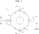
- FIG. 1 is a rear view of the motor 2.
- FIG. 2 is a sectional view of the motor 2 which is taken along a line II-II in FIG. 1 .
- the motor 2 includes a rotor 3, a stator 4, a housing 20, and a pair of covers 10, 30.
- the cover 10 corresponds to a first cover.
- the cover 30 corresponds to a second cover.
- the rotor 3 and the stator 4 are accommodated in a cylindrical housing 20. Both ends in an axial line Ax direction of the housing 20 are opened. One opening (first opening) of the housing 20 is blocked by the cover 10.
- the cover 10 is fixed to the housing 20 with a plurality of bolts 51.
- the other opening (second opening) of the housing 20 is blocked by the cover 30.
- the cover 30 is fixed to the housing 20 with a plurality of bolts 52. In order to distinguish the cover 10 and the cover 30 from each other, the cover 30 may be referred to as "another cover”.
- the stator 4 is fixed inside the housing 20.
- the rotor 3 is rotatably supported by bearings provided in the covers 10, 30.
- a high-voltage current flows through a coil 5 of the stator 4, so that the coil 5 generates heat.
- a refrigerant flow path 21 is provided in the housing 20.
- a liquid refrigerant flows through the refrigerant flow path 21 to cool the coil 5. More specifically, coolant flows through the refrigerant flow path 21.
- FIG. 3 shows a sectional view of the motor 2 which is taken along a line III-III in FIG. 1 .
- FIG. 3 shows a section of the side wall of the housing 20 which is taken along a circumferential direction.
- a plurality of linear flow paths 22 parallel to the axial line Ax are provided in the side wall of the housing 20.
- One ends of adjacent linear flow paths 22 are connected to each other by a U-shaped flow path 12 provided in the cover 10.
- the other ends of the adjacent linear flow paths 22 are connected to each other by a U-shaped flow path 32 provided in the cover 30.
- the U-shaped flow paths 12 and the U-shaped flow paths 32 alternately connect adjacent linear flow paths 22 to each other, and the U-shaped flow paths 12, 32 and the linear flow paths 22 constitute one refrigerant flow path 21.
- the cover 10 is provided with two holes (an air vent hole 13, a drain hole 14) corresponding to first holes, and two other holes (a refrigerant supply port 18, a refrigerant discharge port 19) corresponding to second holes. Totally four of the holes and the other holes all communicate with the inside and outside of the refrigerant flow path 21.
- a refrigerant circulating device (not shown) is connected to the refrigerant supply port 18 and the refrigerant discharge port 19.
- a liquid cold refrigerant is supplied from the refrigerant circulating device to the refrigerant flow path 21.
- the refrigerant flowing through the refrigerant flow path 21 cools the coil 5.
- the refrigerant that has absorbed heat from the coil 5 exits from the refrigerant discharge port 19 and returns to the refrigerant circulating device.
- the air vent hole 13 is normally closed with a bolt 53.
- the drain hole 14 is normally closed with a bolt 54.
- the motor 2 is disposed such that the air vent hole 13 is located at a vertical upper portion of the cover 10 and the drain hole 14 is located at a vertical lower portion of the cover 10. In other words, the air vent hole 13 is located at an upper portion of the cover 10, and the drain hole 14 is located at a lower portion of the cover 10.
- the air vent hole 13 and the drain hole 14 are opened when the motor 2 is stopped to replace the refrigerant.
- the drain hole 14 is opened to drain old refrigerant from the refrigerant flow path 21.
- the drain hole 14 is closed with the bolt 54, and the air vent hole 13 is opened.
- Refrigerant is injected into the refrigerant flow path 21 through the air vent hole 13.
- air in the refrigerant flow path 21 is discharged to the outside through the air vent hole 13.
- air bubbles contained in the refrigerant are also discharged from the air vent hole 13.
- FIG. 3 a symbol T indicates the position of the vertical upper portion of the motor 2, and a symbol B indicates the position of the vertical lower portion of the motor 2.
- FIG. 3 also shows that the air vent hole 13 is located at the vertical upper portion of the cover 10, and the drain hole 14 is located at the vertical lower portion of the cover 10.
- the refrigerant supply port 18 and the refrigerant discharge port 19 are located between the air vent hole 13 and the drain hole 14 in a vertical direction.
- FIG. 4 shows a sectional view of a motor 102 of a second embodiment.
- FIG. 4 is a diagram corresponding to FIG. 2 .
- a bolt 53 for closing an air vent hole 13 fixes a cable bracket 103 to a cover 10.
- the cable bracket 103 supports a power cable 104 for supplying three-phase AC current to a coil 5 of a stator 4.
- the structure of the motor 102 is the same as that of the motor 2 except that the cable bracket 103 is provided.
- the air vent hole 13 is provided at the upper portion in the vertical direction of the cover 10, and the drain hole 14 is provided at the lower portion in the vertical direction thereof. In other words, the air vent hole 13 and the drain hole 14 are located to interpose the axial line Ax therebetween.
- the cover 10 is provided with other holes (the refrigerant supply port 18 and the refrigerant discharge port 19) through which the inside and outside of the refrigerant flow path 21 communicated with each other, as well as the air vent hole 13 and the drain hole 14.
- the diameters of the air vent hole 13 and the drain hole 14 are smaller than the diameters of the refrigerant supply port 18 and the refrigerant discharge port 19.
- the two holes (the air vent hole 13, the drain hole 14) and the two other holes (the refrigerant supply port 18, the refrigerant discharge port 19) all cause the inside and outside of the refrigerant flow path 21 to communicate with each other.
- the other holes (the refrigerant supply port 18 and the refrigerant discharge port 19) are located between the air vent hole 13 and the drain hole 14 in an up-and-down direction (vertical direction).
- the two holes (the air vent hole 13, the drain hole 14) and the two other holes (the refrigerant supply port 18, the refrigerant discharge port 19) are provided in the cover 10, so that the degree of freedom in selecting the locations of the refrigerant supply port 18 and the refrigerant discharge port 19 is enhanced.
- the bolt 53 for securing the motor component (the cable bracket 103) to the cover 10 blocks the air vent hole 13.
- the bolt 53 that blocks the air vent hole 13 also serves as a bolt for fixing the component. This structure contributes to reduction in the number of components in the motor 102.
- the drain hole 14 may also serve as the refrigerant supply port 18, and the air vent hole 13 may also serve as the refrigerant discharge port 19. In other words, only two holes may be provided in the cover 10. In this case, both the holes are not closed.
- the refrigerant enters the refrigerant flow path 21 from the refrigerant supply port 18 (drain hole 14) at the lower portion, and emits from the refrigerant discharge port 19 (air vent hole 13) at the upper portion. Air bubbles contained in the refrigerant are carried along with the flow of the refrigerant and naturally emit from the refrigerant discharge port 19 (air vent hole 13).
- One of the air vent hole 13 and the drain hole 14 may also serve as the refrigerant supply port 18.
- One of the air vent hole 13 and the drain hole 14 may also serve as the refrigerant discharge port 19.
- the refrigerant supply port 18 and the refrigerant discharge port 19 may be provided in the other cover 30 or the housing 20. However, it is desirable that the refrigerant supply port 18 and the refrigerant discharge port 19 are provided in the cover 10 together with the air vent hole 13 and the drain hole 14. By providing four holes in one cover 10, the structures of the housing 20 and the other cover 30 can be simplified.
- the cover 10 blocks one opening of the cylindrical housing 20.
- the other opening of the housing 20 is blocked by the other cover 30.
- the housing 20 may have a cylindrical shape having a bottom. In that case, the motor has only one cover 10.
- the motors 2, 102 of the embodiment have a refrigerant flow path 21 including a plurality of linear flow paths 22 and a plurality of U-shaped flow paths 12, 32.
- the refrigerant flow path 21 may have any shape as long as it is provided inside the wall of the housing 20.
- the bolt 54 that blocks the drain hole 14 may fix the component of the motor.
- the bolts 53, 54 may fix components other than the cable bracket 103 to the cover 30.
Landscapes
- Engineering & Computer Science (AREA)
- Power Engineering (AREA)
- Motor Or Generator Frames (AREA)
- Motor Or Generator Cooling System (AREA)
Abstract
A motor (2; 102) includes a cylindrical housing (20) that accommodates a stator (4) and a rotor (3) inside, a first cover (10) and a second cover (30) that block each axial opening of the housing (20). The housing (20) is provided with a refrigerant flow path (21). The upper portion and the lower portion of the first cover (10) are provided with a first hole (13, 14) each through which an inside and an outside of the refrigerant flow path (21) communicate with each other.
Description
- The invention relates to a motor.
- A motor includes a refrigerant flow path for cooling a coil of a stator. In a motor of
Japanese Unexamined Patent Application Publication No. 11-341744 - Housings having different lengths are required for stators having different lengths. When an air vent hole and a drain hole are provided in each of the housings having different lengths, the structures of the housings are complicated. The present disclosure provides a motor in which the structure of a housing is simple although the motor includes an air vent hole and a drain hole.
- A motor according to an aspect of the present disclosure includes a cylindrical housing that accommodates a stator and a rotor inside, and a first cover that blocks an opening of the housing. The housing is provided with a refrigerant flow path. Each of an upper portion and a lower portion of the first cover is provided with a first hole through which an inside and an outside of the refrigerant flow path communicate with each other. In the motor of the present disclosure, the first cover is provided with two first holes (an air vent hole and a drain hole). Therefore, the structure of the housing is simplified. Furthermore, a common first cover including an air vent hole and a drain hole can be applied to housings of different lengths. Since a common first cover can be applied to housings of different lengths, the degree of freedom in design of motors can be enhanced.
- In the motor, one of the housing and the first cover may be provided with a second hole through which the inside and the outside of the refrigerant flow path communicate with each other.
- In the motor, the second hole may be provided in the first cover.
- Note that one of the two first holes (the air vent hole and the drain hole) may also serve as a refrigerant supply port. The other of the two first holes may also serve as a refrigerant discharge port. In addition to the two first holes, two second holes (a refrigerant supply port and a refrigerant discharge port) may be provided.
- In the motor, the second hole may be located between the two first holes in an up-and-down direction.
- A bolt that fixes a component to the first cover may block the first hole.
- In the motor, the housing may have a first opening and a second opening. The first cover may block the first opening. The motor may include a second cover that blocks the second opening of the housing.
- In the motor, the two first holes may be located to interpose an axial line of the housing between the two first holes.
- In the motor, the first hole is smaller in diameter than the second hole.
- Details and further improvements of the present disclosure are described in the following "Detailed Description of Embodiments".
- Features, advantages, and technical and industrial significance of exemplary embodiments of the invention will be described below with reference to the accompanying drawings, in which like signs denote like elements, and wherein:
-
FIG. 1 is a rear view of a motor of a first embodiment; -
FIG. 2 is a sectional view of the motor which is taken along a line II-II inFIG. 1 ; -
FIG. 3 is a sectional view of the motor which is taken along a line III-III inFIG. 1 ; and -
FIG. 4 is a sectional view of a motor of a second embodiment. - A
motor 2 of a first embodiment will be described with reference toFIGS. 1 to 3 .FIG. 1 is a rear view of themotor 2.FIG. 2 is a sectional view of themotor 2 which is taken along a line II-II inFIG. 1 . Themotor 2 includes arotor 3, astator 4, ahousing 20, and a pair ofcovers cover 10 corresponds to a first cover. Thecover 30 corresponds to a second cover. Therotor 3 and thestator 4 are accommodated in acylindrical housing 20. Both ends in an axial line Ax direction of thehousing 20 are opened. One opening (first opening) of thehousing 20 is blocked by thecover 10. Thecover 10 is fixed to thehousing 20 with a plurality ofbolts 51. The other opening (second opening) of thehousing 20 is blocked by thecover 30. Thecover 30 is fixed to thehousing 20 with a plurality ofbolts 52. In order to distinguish thecover 10 and thecover 30 from each other, thecover 30 may be referred to as "another cover". Thestator 4 is fixed inside thehousing 20. Therotor 3 is rotatably supported by bearings provided in thecovers - While the
motor 2 is operating, a high-voltage current flows through acoil 5 of thestator 4, so that thecoil 5 generates heat. In order to cool thecoil 5, arefrigerant flow path 21 is provided in thehousing 20. A liquid refrigerant flows through therefrigerant flow path 21 to cool thecoil 5. More specifically, coolant flows through therefrigerant flow path 21. - The structure of the
refrigerant flow path 21 will be described.Linear flow paths 22 are provided inside the side wall of thehousing 20.FIG. 3 shows a sectional view of themotor 2 which is taken along a line III-III inFIG. 1 .FIG. 3 shows a section of the side wall of thehousing 20 which is taken along a circumferential direction. A plurality oflinear flow paths 22 parallel to the axial line Ax are provided in the side wall of thehousing 20. One ends of adjacentlinear flow paths 22 are connected to each other by aU-shaped flow path 12 provided in thecover 10. The other ends of the adjacentlinear flow paths 22 are connected to each other by aU-shaped flow path 32 provided in thecover 30. TheU-shaped flow paths 12 and theU-shaped flow paths 32 alternately connect adjacentlinear flow paths 22 to each other, and theU-shaped flow paths linear flow paths 22 constitute onerefrigerant flow path 21. - The
cover 10 is provided with two holes (anair vent hole 13, a drain hole 14) corresponding to first holes, and two other holes (arefrigerant supply port 18, a refrigerant discharge port 19) corresponding to second holes. Totally four of the holes and the other holes all communicate with the inside and outside of therefrigerant flow path 21. A refrigerant circulating device (not shown) is connected to therefrigerant supply port 18 and therefrigerant discharge port 19. A liquid cold refrigerant is supplied from the refrigerant circulating device to therefrigerant flow path 21. The refrigerant flowing through therefrigerant flow path 21 cools thecoil 5. The refrigerant that has absorbed heat from thecoil 5 exits from therefrigerant discharge port 19 and returns to the refrigerant circulating device. - The
air vent hole 13 is normally closed with abolt 53. Thedrain hole 14 is normally closed with abolt 54. Themotor 2 is disposed such that theair vent hole 13 is located at a vertical upper portion of thecover 10 and thedrain hole 14 is located at a vertical lower portion of thecover 10. In other words, theair vent hole 13 is located at an upper portion of thecover 10, and thedrain hole 14 is located at a lower portion of thecover 10. - The
air vent hole 13 and thedrain hole 14 are opened when themotor 2 is stopped to replace the refrigerant. First, thedrain hole 14 is opened to drain old refrigerant from therefrigerant flow path 21. Thedrain hole 14 is closed with thebolt 54, and theair vent hole 13 is opened. Refrigerant is injected into therefrigerant flow path 21 through theair vent hole 13. At the same time when the refrigerant fills therefrigerant flow path 21, air in therefrigerant flow path 21 is discharged to the outside through theair vent hole 13. At this time, air bubbles contained in the refrigerant are also discharged from theair vent hole 13. When theair vent hole 13 is closed with thebolt 53, themotor 2 is ready to be driven. - In
FIG. 3 , a symbol T indicates the position of the vertical upper portion of themotor 2, and a symbol B indicates the position of the vertical lower portion of themotor 2.FIG. 3 also shows that theair vent hole 13 is located at the vertical upper portion of thecover 10, and thedrain hole 14 is located at the vertical lower portion of thecover 10. Therefrigerant supply port 18 and therefrigerant discharge port 19 are located between theair vent hole 13 and thedrain hole 14 in a vertical direction. -
FIG. 4 shows a sectional view of amotor 102 of a second embodiment.FIG. 4 is a diagram corresponding toFIG. 2 . In themotor 102, abolt 53 for closing anair vent hole 13 fixes acable bracket 103 to acover 10. Thecable bracket 103 supports apower cable 104 for supplying three-phase AC current to acoil 5 of astator 4. The structure of themotor 102 is the same as that of themotor 2 except that thecable bracket 103 is provided. - Some features and effects of the
motors air vent hole 13 is provided at the upper portion in the vertical direction of thecover 10, and thedrain hole 14 is provided at the lower portion in the vertical direction thereof. In other words, theair vent hole 13 and thedrain hole 14 are located to interpose the axial line Ax therebetween. Thecover 10 is provided with other holes (therefrigerant supply port 18 and the refrigerant discharge port 19) through which the inside and outside of therefrigerant flow path 21 communicated with each other, as well as theair vent hole 13 and thedrain hole 14. The diameters of theair vent hole 13 and thedrain hole 14 are smaller than the diameters of therefrigerant supply port 18 and therefrigerant discharge port 19. The two holes (theair vent hole 13, the drain hole 14) and the two other holes (therefrigerant supply port 18, the refrigerant discharge port 19) all cause the inside and outside of therefrigerant flow path 21 to communicate with each other. The other holes (therefrigerant supply port 18 and the refrigerant discharge port 19) are located between theair vent hole 13 and thedrain hole 14 in an up-and-down direction (vertical direction). - No hole is provided in the
cylindrical housings 20 of themotors housing 20.Different housings 20 are prepared according to the length of thestator 4. Acommon cover 10 can be adopted for thehousings 20 having different lengths. Since thecover 10 can be made common for thehousings 20 having different lengths, the degree of freedom of design can be enhanced for themotors - The two holes (the
air vent hole 13, the drain hole 14) and the two other holes (therefrigerant supply port 18, the refrigerant discharge port 19) are provided in thecover 10, so that the degree of freedom in selecting the locations of therefrigerant supply port 18 and therefrigerant discharge port 19 is enhanced. - In the
motor 102 of the second embodiment, thebolt 53 for securing the motor component (the cable bracket 103) to thecover 10 blocks theair vent hole 13. Thebolt 53 that blocks theair vent hole 13 also serves as a bolt for fixing the component. This structure contributes to reduction in the number of components in themotor 102. - Points to be noted for the technique described in the embodiment will be described below. The
drain hole 14 may also serve as therefrigerant supply port 18, and theair vent hole 13 may also serve as therefrigerant discharge port 19. In other words, only two holes may be provided in thecover 10. In this case, both the holes are not closed. The refrigerant enters therefrigerant flow path 21 from the refrigerant supply port 18 (drain hole 14) at the lower portion, and emits from the refrigerant discharge port 19 (air vent hole 13) at the upper portion. Air bubbles contained in the refrigerant are carried along with the flow of the refrigerant and naturally emit from the refrigerant discharge port 19 (air vent hole 13). - One of the
air vent hole 13 and thedrain hole 14 may also serve as therefrigerant supply port 18. One of theair vent hole 13 and thedrain hole 14 may also serve as therefrigerant discharge port 19. - The
refrigerant supply port 18 and therefrigerant discharge port 19 may be provided in theother cover 30 or thehousing 20. However, it is desirable that therefrigerant supply port 18 and therefrigerant discharge port 19 are provided in thecover 10 together with theair vent hole 13 and thedrain hole 14. By providing four holes in onecover 10, the structures of thehousing 20 and theother cover 30 can be simplified. - The
cover 10 blocks one opening of thecylindrical housing 20. The other opening of thehousing 20 is blocked by theother cover 30. Thehousing 20 may have a cylindrical shape having a bottom. In that case, the motor has only onecover 10. Themotors refrigerant flow path 21 including a plurality oflinear flow paths 22 and a plurality ofU-shaped flow paths refrigerant flow path 21 may have any shape as long as it is provided inside the wall of thehousing 20. - The
bolt 54 that blocks thedrain hole 14 may fix the component of the motor. Thebolts cable bracket 103 to thecover 30. - Although the specific examples of the present disclosure have been described above in detail, these are merely examples, and do not limit the scope of the claims. The technique described in the claims includes various modifications and changes which will be made in the specific examples illustrated above. The technical elements described in the present specification or drawings exhibit technical utility alone or in various combinations, and are not limited to the combinations described in the claims at the time of filing. Furthermore, the technique illustrated in the present specification or drawings can achieve a plurality of objects simultaneously, and has technical utility by achieving one of the objects itself.
Claims (8)
- A motor (2; 102) comprising:a cylindrical housing (20) that accommodates a stator (4) and a rotor (3) inside; anda first cover (10) that blocks an opening of the housing (20),wherein the housing (20) is provided with a refrigerant flow path (21), andwherein each of an upper portion and a lower portion of the first cover (10) is provided with a first hole (13, 14) through which an inside and an outside of the refrigerant flow path (21) communicate with each other.
- The motor (2; 102) according to claim 1, wherein one of the housing (20) and the first cover (10) is provided with a second hole (18, 19) through which the inside and the outside of the refrigerant flow path (21) communicate with each other.
- The motor (2; 102) according to claim 2, wherein the second hole (18, 19) is provided in the first cover (10).
- The motor (2; 102) according to claim 3, wherein the second hole (18, 19) is located between the two first holes (13, 14) in an up-and-down direction.
- The motor (2; 102) according to claim 1, wherein a bolt (53, 54) that fixes a component to the first cover (10) blocks the first hole (13, 14).
- The motor (2; 102) according to claim 1,wherein the housing (20) has a first opening and a second opening,wherein the first cover (10) blocks the first opening, andwherein the motor includes a second cover (30) that blocks the second opening of the housing (20).
- The motor (2; 102) according to claim 1, wherein the two first holes (13, 14) are located to interpose an axial line (Ax) of the housing (20) between the two first holes (13, 14).
- The motor (2; 102) according to claim 2, wherein the first hole (13, 14) is smaller in diameter than the second hole (18, 19).
Applications Claiming Priority (1)
| Application Number | Priority Date | Filing Date | Title |
|---|---|---|---|
| JP2023205238A JP2025090167A (en) | 2023-12-05 | 2023-12-05 | Motor |
Publications (1)
| Publication Number | Publication Date |
|---|---|
| EP4568076A1 true EP4568076A1 (en) | 2025-06-11 |
Family
ID=93704565
Family Applications (1)
| Application Number | Title | Priority Date | Filing Date |
|---|---|---|---|
| EP24215705.5A Pending EP4568076A1 (en) | 2023-12-05 | 2024-11-27 | Motor comprising a cooling jacket |
Country Status (5)
| Country | Link |
|---|---|
| US (1) | US20250183749A1 (en) |
| EP (1) | EP4568076A1 (en) |
| JP (1) | JP2025090167A (en) |
| KR (1) | KR20250085611A (en) |
| CN (1) | CN120110072A (en) |
Citations (4)
| Publication number | Priority date | Publication date | Assignee | Title |
|---|---|---|---|---|
| JPH11341744A (en) | 1998-05-25 | 1999-12-10 | Mitsubishi Electric Corp | Water cooling structure of motor |
| KR20140109313A (en) * | 2013-03-04 | 2014-09-15 | 레미 테크놀러지스 엘엘씨 | Liquid-cooled rotary electric machine having cooling jacket with bi-directional flow |
| KR20210064656A (en) * | 2019-11-26 | 2021-06-03 | 주식회사 맥시스 | Drive motor for electric vehicle having enhanced cooling efficiency of bearing |
| DE102021203301A1 (en) * | 2021-03-31 | 2022-10-06 | Valeo Siemens Eautomotive Germany Gmbh | Electrical machine with a pressure compensation element |
Family Cites Families (4)
| Publication number | Priority date | Publication date | Assignee | Title |
|---|---|---|---|---|
| JPH0454465U (en) * | 1990-09-10 | 1992-05-11 | ||
| JP2919820B2 (en) * | 1996-12-23 | 1999-07-19 | マンド マシナリー コーポレーション | Drive motor for electric vehicles |
| JP2016046853A (en) * | 2014-08-20 | 2016-04-04 | 株式会社豊田自動織機 | Rotary electric machine |
| JP6470676B2 (en) * | 2015-12-24 | 2019-02-13 | 株式会社クボタ | Liquid cooling motor |
-
2023
- 2023-12-05 JP JP2023205238A patent/JP2025090167A/en active Pending
-
2024
- 2024-11-21 CN CN202411671194.8A patent/CN120110072A/en active Pending
- 2024-11-21 US US18/955,159 patent/US20250183749A1/en active Pending
- 2024-11-22 KR KR1020240168520A patent/KR20250085611A/en active Pending
- 2024-11-27 EP EP24215705.5A patent/EP4568076A1/en active Pending
Patent Citations (4)
| Publication number | Priority date | Publication date | Assignee | Title |
|---|---|---|---|---|
| JPH11341744A (en) | 1998-05-25 | 1999-12-10 | Mitsubishi Electric Corp | Water cooling structure of motor |
| KR20140109313A (en) * | 2013-03-04 | 2014-09-15 | 레미 테크놀러지스 엘엘씨 | Liquid-cooled rotary electric machine having cooling jacket with bi-directional flow |
| KR20210064656A (en) * | 2019-11-26 | 2021-06-03 | 주식회사 맥시스 | Drive motor for electric vehicle having enhanced cooling efficiency of bearing |
| DE102021203301A1 (en) * | 2021-03-31 | 2022-10-06 | Valeo Siemens Eautomotive Germany Gmbh | Electrical machine with a pressure compensation element |
Also Published As
| Publication number | Publication date |
|---|---|
| CN120110072A (en) | 2025-06-06 |
| US20250183749A1 (en) | 2025-06-05 |
| JP2025090167A (en) | 2025-06-17 |
| KR20250085611A (en) | 2025-06-12 |
Similar Documents
| Publication | Publication Date | Title |
|---|---|---|
| JP7559752B2 (en) | Motor Unit | |
| CN111585394B (en) | Motor unit | |
| CN114901499B (en) | Driving device | |
| US20140239755A1 (en) | Rotating electrical machine | |
| JP7363154B2 (en) | Motor unit and motor unit manufacturing method | |
| US20210336506A1 (en) | Motor | |
| US20140239758A1 (en) | Rotating electrical machine | |
| CN114362449A (en) | Drive device | |
| US10958136B2 (en) | Drive apparatus | |
| US11139720B2 (en) | Drive apparatus | |
| EP4568076A1 (en) | Motor comprising a cooling jacket | |
| EP4027489A1 (en) | Fluid cooled electric machine | |
| JP4645200B2 (en) | Rotating electric machine stator and rotating electric machine | |
| JP2022128993A (en) | Rotary electric machine and driving device | |
| US20200295627A1 (en) | Rotating electric machine and motor unit | |
| CN118476144A (en) | Rotary electric machine and vehicle driving device provided with same | |
| KR20250095496A (en) | Motor | |
| JP5957803B2 (en) | Rotating electric machine | |
| JP7468313B2 (en) | Drive unit | |
| JP6871077B2 (en) | Motor generator device | |
| CN115244833B (en) | Electric system | |
| CN116373584A (en) | drive unit for vehicle | |
| JP2016007106A (en) | Rotary electric machine and vehicle drive unit | |
| KR20190142184A (en) | Electric motor | |
| CN119813625B (en) | Motor cooling components, motors, electric drive systems and vehicles |
Legal Events
| Date | Code | Title | Description |
|---|---|---|---|
| PUAI | Public reference made under article 153(3) epc to a published international application that has entered the european phase |
Free format text: ORIGINAL CODE: 0009012 |
|
| STAA | Information on the status of an ep patent application or granted ep patent |
Free format text: STATUS: REQUEST FOR EXAMINATION WAS MADE |
|
| 17P | Request for examination filed |
Effective date: 20241127 |
|
| AK | Designated contracting states |
Kind code of ref document: A1 Designated state(s): AL AT BE BG CH CY CZ DE DK EE ES FI FR GB GR HR HU IE IS IT LI LT LU LV MC ME MK MT NL NO PL PT RO RS SE SI SK SM TR |