EP4567996A2 - Batteriemodul - Google Patents
Batteriemodul Download PDFInfo
- Publication number
- EP4567996A2 EP4567996A2 EP24792888.0A EP24792888A EP4567996A2 EP 4567996 A2 EP4567996 A2 EP 4567996A2 EP 24792888 A EP24792888 A EP 24792888A EP 4567996 A2 EP4567996 A2 EP 4567996A2
- Authority
- EP
- European Patent Office
- Prior art keywords
- battery module
- cover
- venting hole
- battery
- present disclosure
- Prior art date
- Legal status (The legal status is an assumption and is not a legal conclusion. Google has not performed a legal analysis and makes no representation as to the accuracy of the status listed.)
- Pending
Links
Images


Classifications
-
- H—ELECTRICITY
- H01—ELECTRIC ELEMENTS
- H01M—PROCESSES OR MEANS, e.g. BATTERIES, FOR THE DIRECT CONVERSION OF CHEMICAL ENERGY INTO ELECTRICAL ENERGY
- H01M50/00—Constructional details or processes of manufacture of the non-active parts of electrochemical cells other than fuel cells, e.g. hybrid cells
- H01M50/30—Arrangements for facilitating escape of gases
- H01M50/35—Gas exhaust passages comprising elongated, tortuous or labyrinth-shaped exhaust passages
- H01M50/358—External gas exhaust passages located on the battery cover or case
-
- H—ELECTRICITY
- H01—ELECTRIC ELEMENTS
- H01M—PROCESSES OR MEANS, e.g. BATTERIES, FOR THE DIRECT CONVERSION OF CHEMICAL ENERGY INTO ELECTRICAL ENERGY
- H01M50/00—Constructional details or processes of manufacture of the non-active parts of electrochemical cells other than fuel cells, e.g. hybrid cells
- H01M50/20—Mountings; Secondary casings or frames; Racks, modules or packs; Suspension devices; Shock absorbers; Transport or carrying devices; Holders
- H01M50/271—Lids or covers for the racks or secondary casings
- H01M50/273—Lids or covers for the racks or secondary casings characterised by the material
- H01M50/276—Inorganic material
-
- H—ELECTRICITY
- H01—ELECTRIC ELEMENTS
- H01M—PROCESSES OR MEANS, e.g. BATTERIES, FOR THE DIRECT CONVERSION OF CHEMICAL ENERGY INTO ELECTRICAL ENERGY
- H01M50/00—Constructional details or processes of manufacture of the non-active parts of electrochemical cells other than fuel cells, e.g. hybrid cells
- H01M50/30—Arrangements for facilitating escape of gases
- H01M50/342—Non-re-sealable arrangements
- H01M50/3425—Non-re-sealable arrangements in the form of rupturable membranes or weakened parts, e.g. pierced with the aid of a sharp member
-
- H—ELECTRICITY
- H01—ELECTRIC ELEMENTS
- H01M—PROCESSES OR MEANS, e.g. BATTERIES, FOR THE DIRECT CONVERSION OF CHEMICAL ENERGY INTO ELECTRICAL ENERGY
- H01M50/00—Constructional details or processes of manufacture of the non-active parts of electrochemical cells other than fuel cells, e.g. hybrid cells
- H01M50/30—Arrangements for facilitating escape of gases
- H01M50/383—Flame arresting or ignition-preventing means
-
- H—ELECTRICITY
- H01—ELECTRIC ELEMENTS
- H01M—PROCESSES OR MEANS, e.g. BATTERIES, FOR THE DIRECT CONVERSION OF CHEMICAL ENERGY INTO ELECTRICAL ENERGY
- H01M50/00—Constructional details or processes of manufacture of the non-active parts of electrochemical cells other than fuel cells, e.g. hybrid cells
- H01M50/20—Mountings; Secondary casings or frames; Racks, modules or packs; Suspension devices; Shock absorbers; Transport or carrying devices; Holders
- H01M50/249—Mountings; Secondary casings or frames; Racks, modules or packs; Suspension devices; Shock absorbers; Transport or carrying devices; Holders specially adapted for aircraft or vehicles, e.g. cars or trains
-
- Y—GENERAL TAGGING OF NEW TECHNOLOGICAL DEVELOPMENTS; GENERAL TAGGING OF CROSS-SECTIONAL TECHNOLOGIES SPANNING OVER SEVERAL SECTIONS OF THE IPC; TECHNICAL SUBJECTS COVERED BY FORMER USPC CROSS-REFERENCE ART COLLECTIONS [XRACs] AND DIGESTS
- Y02—TECHNOLOGIES OR APPLICATIONS FOR MITIGATION OR ADAPTATION AGAINST CLIMATE CHANGE
- Y02E—REDUCTION OF GREENHOUSE GAS [GHG] EMISSIONS, RELATED TO ENERGY GENERATION, TRANSMISSION OR DISTRIBUTION
- Y02E60/00—Enabling technologies; Technologies with a potential or indirect contribution to GHG emissions mitigation
- Y02E60/10—Energy storage using batteries
Definitions
- the present disclosure relates to a battery module.
- lithium secondary batteries are in the spotlight for their advantages of free charging and discharging due to almost no memory effect, a very low self-discharge rate, and a high energy density, compared to nickel-based secondary batteries.
- Lithium secondary batteries use lithium-based oxides and carbon materials as positive and negative electrode active materials, respectively.
- the lithium secondary batteries include an electrode assembly in which the positive and negative electrode plates, which are respectively coated with the positive and negative electrode active materials, are disposed with a separator therebetween, and an exterior case, i.e., a battery case, that seals and stores the electrode assembly with an electrolyte.
- lithium secondary batteries may be classified, depending on the shape of the exterior case, into can-type secondary batteries in which the electrode assembly is stored in a metal may and pouch-type secondary batteries in which the electrode assembly is stored in a pouch of an aluminum laminate sheet.
- secondary batteries have been widely used in medium and large devices such as electric vehicles and energy storage systems (ESSs) for driving and storing energy, as well as in small devices such as portable electronic devices.
- a plurality of secondary batteries may be electrically connected and stored inside a module case to form a battery module.
- each secondary battery included in the battery module may be referred to as a battery cell.
- multiple battery modules may be connected to each other to form a battery pack.
- a battery pack includes multiple battery modules therein and where each battery module includes multiple battery cells, it may be vulnerable to a chain thermal reaction between the battery modules or between the battery cells. For example, if an event such as thermal runaway occurs inside one battery module, the thermal runaway needs to be prevented from transferring to other battery modules or other battery cells. If the propagation of thermal runaway between the battery modules or the battery cells fails to be properly suppressed, an event occurring in a specific battery module or battery cell may cause a chain thermal reaction in other battery modules or other battery cells, leading to explosion or fire and worsening the same.
- gas or flame may be randomly discharged to the outside.
- the gas or flame will be discharged to other battery modules, causing a chain thermal reaction in other battery modules.
- a module terminal may be provided on the front side of the battery module, and for example, a configuration, such as a module bus-bar, to be electrically connected to another battery module or battery pack may be provided thereon. Therefore, if flame is discharged toward the front of the battery module, the module terminal may be damaged in the battery pack, causing electrical short circuits.
- other battery modules may exist in front of a battery module, so if flame is discharged toward the front of a specific battery module, the discharged flame may be directed to another battery module, making it easy for fire to spread between the battery modules.
- the voltage of the battery module or battery pack may rapidly drop. In addition, this may cause sudden interruption of devices equipped with the battery modules or battery packs, resulting in unexpected damage. For example, if the voltage suddenly drops in the battery pack while the electric vehicle is driving, it is impossible to secure enough time to move the electric vehicle to a safe location.
- the present disclosure has been designed to solve the problems of the related art, and therefore the present disclosure is directed to providing a battery module with an improved structure capable of appropriately controlling the discharge of flame or the like generated inside the battery module, and a battery pack and vehicle including the same.
- a battery module including: a case having a space therein and a first venting hole formed on an upper surface thereof; a plurality of battery cells provided inside the case; a first cover configured to cover the upper surface of the case and having a second venting hole facing the first venting hole; and a second cover configured to cover the first cover and having a score line facing the second venting hole.
- the score line may be configured to rupture when a thermal event occurs in the battery cell.
- the score line may extend along the perimeter of the second venting hole.
- the first cover may include a bridge configured to partition the second venting hole.
- the bridge may support the second cover.
- the second venting hole may be configured as a plurality of holes.
- the second cover may be thicker than the first cover.
- the score line may form a separation area.
- the second venting hole may be formed to be smaller than the separation area.
- the separation area may be formed to be larger than the first venting hole.
- a plurality of first venting holes may be provided.
- the first venting hole may face at least some of the plurality of battery cells.
- the first cover may include a mica material.
- the second cover may include a mica material.
- a battery pack including the battery module according to the present disclosure.
- a vehicle including the battery module according to the present disclosure.
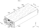
- FIG. 1 is a drawing illustrating a battery module according to an embodiment of the present disclosure.
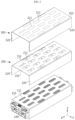
- FIG. 2 is a drawing illustrating the battery module in FIG. 1 in which some elements are exploded.
- FIG. 3 is a drawing illustrating the battery assembly in FIG. 2 in which some elements are exploded.
- a battery module may include a case 110, a plurality of battery cells 120, a first cover 200, and a second cover 300.
- the case 110 may have a cuboid shape.
- the case 110 may also be referred to as a frame 110.
- the case 110 may provide a space therein.
- the case 110 may have an upper surface, a lower surface, and a pair of side surfaces.
- the case 110 may have open front and end sides.
- the case 110 may have a first venting hole 111 on the upper surface.
- the first venting hole 111 may connect the inside and the outside of the case 110.
- the plurality of battery cells 120 may be stacked in the left/right direction or the Y-axis direction.
- the battery cell 120 may indicate a secondary battery.
- the secondary battery may be equipped with an electrode assembly, an electrolyte, an electrode lead 121, and a battery case.
- the battery cell 120 may be a pouch-type secondary battery.
- Each battery cell 120 may extend in the front/back direction or the X-axis direction.
- the electrode lead 121 may protrude forward and backward from each battery cell 120.
- the compression pads 150 may be disposed between a plurality of battery cells 120.
- the compression pads 150 may be disposed between at least some of the battery cells 120 and/or the outer side of the stack.
- the compression pads 150 may be disposed between every four battery cells 120 stacked in the left/right direction.
- the compression pad 150 may be made of an elastic material to absorb swelling of the battery cell 120.
- the compression pad 150 may be made of a foam material such as polyurethane.
- the compression pad 150 may be made of a material capable of blocking heat or flame.
- the compression pad 150 may be made of a heat-resistant or fire-retardant material such as silicon or mica.
- the bus-bar frame assembly 130 may be provided at the front and rear of the plurality of battery cells 120, respectively.
- the bus-bar frame assembly 130 may be electrically connected to the electrode leads 121 of the plurality of battery cells 120.
- a pair of end covers 140 may be coupled to the front and rear sides of the case 210, respectively.
- the pair of end covers 140 may cover the front and rear sides of the case 210.
- the end cover 140 may have a square shape.
- the first cover 200 may cover the upper surface of the case 110.
- the first cover 200 may have a second venting hole 211 facing the first venting hole 111.
- the first venting hole 111 and the second venting hole 211 may face each other.
- the first venting hole 111 and the second venting hole 211 may have very similar sizes.
- the first cover 200 may be attached, fixed, coupled, or fastened to the upper surface of the case 110.
- the first cover 200 may include a first top part 210 and a pair of first side parts 220.
- the first top part 210 and the pair of first side parts 220 may each have a plate shape.
- the first top part 210 and the pair of first side parts 220 may be formed integrally.
- the first top part 210 may be attached, fixed, coupled, or fastened to the upper surface of the case 110.
- the pair of first side parts 220 may be attached, fixed, coupled, or fastened to a pair of side surfaces of the case 110, respectively.
- the second cover 300 may cover the first cover 200.
- the second cover 300 may have a score line 311 facing the second venting hole 211.
- the second cover 300 may include a second top part 310 and a pair of second side parts 320.
- the second top part 310 and the pair of second side parts 320 may each have a plate shape.
- the second top part 310 and the pair of second side parts 320 may be formed integrally.
- the second top part 310 may be attached, fixed, coupled, or fastened to the upper surface of the first top part 210.
- the pair of second side parts 320 may be attached, fixed, coupled, or fastened to the pair of first side parts 220, respectively.
- the score line 311 may be used as a term that encompasses or indicates a perforated line 311, a notching line 311, a cutting line 311, a shredding line 311, a tear line 311, or a separation line 311.
- the score line 311 may be configured to easily rupture by pressure applied to the second cover 300.
- venting gas may pressurize the second cover 300 by passing through the first venting hole 111 and the second venting hole 211.
- the venting gas may push the score line 311 to separate at least a position of the second cover 300 or form a hole.
- the inside and the outside of the battery module may communicate each other, so that the venting gas may be discharged to the outside of the battery module.
- the second cover 300 may prevent or block high-temperature gas or ignitable particles generated outside the battery module from flowing into the case 110. As a result, it is possible to block propagation of the thermal event to the battery cell 120 inside the case 110.
- the score line 311 of the battery module may be configured to rupture for separation when a thermal event occurs in the battery cell 120.
- the thermal safety of the battery module may be improved.
- the score line 311 of the battery module may extend along the perimeter of the second venting hole 211.
- the score line 311 may be formed in the area facing the second venting hole 211.
- the thermal safety of the battery module may be improved.
- the score line 311 may easily rupture.
- the venting gas may be easily discharged.
- the score line 311 of the battery module may form a separation area 312.
- the separation area 312 may be an area surrounded by the score line 311.
- the thermal safety of the battery module may be improved.
- the separation area 312 formed by the score line 311 may be completely separated from the second cover 300.
- the venting gas may be easily discharged.
- the first cover 200 of the battery module may include a bridge 212.
- the bridge 212 may divide the second venting hole 211 into a plurality of holes 211a.
- the bridge 212 may be formed integrally with the first cover 200.
- the bridge 212 may be positioned between a plurality of holes 211a constituting the second venting hole 211.
- the bridge 212 may face the first venting hole 111.
- the bridge 212 may be in contact with the second cover 300.
- the bridge 212 may improve the rigidity of the first cover 200.
- the bridge 212 may stably support the second cover 300.
- the bridge 212 may prevent the score line 311 of the second cover 300 from easily rupturing by high-temperature gas or ignitable particles generated outside the battery module.
- the score line 311 may not prevent the score line 311 of the second cover 300 from easily rupturing when a thermal event occurs inside the battery module.
- a plurality of first venting holes 111 may be provided in the battery module according to an embodiment of the present disclosure.
- a plurality of second venting holes 211 may be provided and positioned to correspond one-to-one to the first venting holes 111.
- a plurality of score lines 311 may be provided and positioned to correspond one-to-one to the second venting holes 211.
- the thermal safety of the battery module may be improved.
- the venting gas generated inside the battery module may be effectively discharged to the outside.
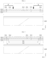
- FIG. 4 is a cross-sectional view taken along line A-A' in FIG. 1 .
- the first venting hole 111 may face at least some of the plurality of battery cells 120.
- the first venting hole 111 may face at least some of the upper surfaces of the plurality of battery cells 120.
- the second venting hole 211 may face at least some of the plurality of battery cells 120.
- the second venting hole 211 may face at least some of the upper surfaces of the plurality of battery cells 120.
- the second cover 300 or the separation area 312 may face at least some of the plurality of battery cells 120.
- the second cover 300 or the separation area 312 may face at least some of the upper surfaces of the plurality of battery cells 120.
- venting gas may be discharged through the upper side or upper surface of the battery cell 120.
- the venting gas may be discharged to the outside of the battery module through the first venting hole 111, the second venting hole 211, and the separation area 312.
- the first cover 200 may include a heat-resistant material.
- the first cover 200 may include a ceramic material such as mica.
- the thermal safety of the battery module may be improved.
- the first cover 200 may stably maintain its shape even when exposed to high-temperature gas resulting from the occurrence of a thermal event.
- the second cover 300 may include a heat-resistant material.
- the second cover 300 may include a ceramic material such as mica.
- the thermal safety of the battery module may be improved.
- the second cover 300 may stably maintain its shape even when exposed to high-temperature gas due to a thermal event.
- the second cover 300 of the battery module may be thicker than the first cover 200.
- the second cover 300 may have a higher hardness than the first cover 200.
- the battery module may have higher thermal resistance to flame or high-temperature gas generated from the outside.
- the bonding state between the second cover 300 and the first cover 200 or the case 110 may not be maintained. As a result, a gap may be produced between the second cover 300 and the first cover 200 or between the second cover 300 and the case 110. In addition, high-temperature gas may be trapped in the gap, which may degrade the thermal stability of the battery module.
- the second cover 300 since the second cover 300 has a high hardness, when venting gas is discharged from the inside of the battery module, the bonding state of the first cover 200 or the case 110 may be stably maintained.
- an adhesive member may be disposed between the first cover 200 and the case 110 of the battery module according to an embodiment of the present disclosure.
- an adhesive member may be disposed between the first cover 200 and the second cover 300.
- an insulating film may be disposed between the first cover 200 and the case 110.
- the insulating film may be made of an electrically insulating material such as plastic.
- the insulating film may be made of a polyurethane material.
- the insulating film may be bonded to the case 110 and/or the first cover 200.
- the insulating film may have adhesive applied to both sides, thereby bonding the case 110 and the first cover 200 to each other.
- FIG. 5 is a drawing illustrating the configuration of FIG. 4 when a thermal event occurs inside the battery module.
- the separation area 312 of the battery module may be separated from the second cover 300 when a thermal event occurs.
- the separation area 312 may be separated along the score line 311.
- a third venting hole 313 may be formed in the second cover 300.
- the third venting hole 313 may face the first venting hole 111 and the second venting hole 211.
- the third venting hole 313 may be connected to the first venting hole 111 and the second venting hole 211.
- the venting gas g may sequentially pass through the first venting hole 111, the second venting hole 211, and the third venting hole 313 and may be discharged to the outside of the battery module.
- FIG. 6 is a drawing illustrating the configuration of FIG. 4 when a thermal event occurs outside the battery module.
- the bridge 212 of the battery module may support the second cover 300.
- the bridge 212 may support the separation area 312.
- the separation area 312 may be pressurized by flames, ignitable particles, or venting gas g generated outside the battery module.
- the bridge 212 may come into contact with or support the lower surface of the separation area 312 to prevent the separation area 312 from being separated from the second cover 300.
- the thermal safety of the battery module may be improved.
- the second cover 300 may prevent flame or venting gas from flowing into the case 110 from the outside. As a result, heat propagation into the battery module may be blocked.
- FIG. 7 is a drawing illustrating a modified embodiment of FIG. 4 .
- the size of the second venting hole 211 of the battery module may be configured to be less than the size of the separation area 312.
- the diameter D1 of the second venting hole 211 may be configured to be smaller than the diameter D2 of the separation area 312.
- the diameter D1 of the first venting hole 111 may be configured to be smaller than the diameter D2 of the separation area 312.
- the diameters D1 of the first venting hole 111 and the second venting hole 211 may be configured to be substantially the same.
- the separation area 312 may be formed to be larger than the first venting hole 111. In addition, the separation area 312 may be formed to be larger than the second venting hole 211.
- the first cover 200 may support the perimeter of the separation area 312. Therefore, the thermal safety of the battery module may be improved.
- the second cover 300 may prevent flame or venting gas from flowing into the case 110 from the outside. Therefore, heat propagation into the interior of the battery module may be blocked.
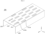
- FIG. 8 is a drawing illustrating a modified embodiment of the first cover 200 in FIG. 2 .
- a plurality of second venting holes 211 may be provided in the battery module according to an embodiment of the present disclosure.
- each second venting hole 211 may be configured as a plurality of holes 211b.
- a plurality of bridges 212a may be provided to partition the second venting hole 211.
- the bridge 212a may be configured to cross the hole. Therefore, the second venting hole 211 may be divided into four holes 211b.
- the area of the bridge 212a supporting the second cover 300 may be increased. Therefore, the bridge 212a may support the second cover 300 more stably.
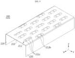
- FIG. 9 is a drawing illustrating another modified embodiment of the first cover 200 in FIG. 2 .
- a plurality of second venting hole 211 may be provided in the battery module according to an embodiment of the present disclosure.
- each second venting holes 211 may be configured as a plurality of holes 211c.
- a plurality of bridges 212b may be provide to partition the second venting holes 211.
- a pair of the bridge 212b may be provided so as to face each other. Therefore, the second venting hole 211 may be partitioned into three holes 211c.
- the area of the bridge 212b supporting the second cover 300 may be increased. Therefore, the bridge 212b may support the second cover 300 more stably.
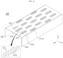
- FIG. 10 is a drawing illustrating another modified embodiment of the first cover 200 in FIG. 2 .
- a plurality of second venting holes 211 may be provided in the battery module according to an embodiment of the present disclosure.
- each second venting hole 211 may be configured as a plurality of holes 211d.
- the plurality of holes 211d constituting the second venting hole 211 may be located within an opposing area 213.
- the opposing area 213 may be an area facing the separation area 312.
- the opposing area 213 and the separation area 312 may have substantially the same size and substantially the same shape.
- a portion, which divides the second venting hole 211 into a plurality of holes 211d may be called a bridge 212c.
- the bridge 212c may divide the second venting hole 211 into six holes 211d.
- the area of the bridge 212c supporting the second cover 300 may be increased. Therefore, the bridge 212c may support the second cover 300 more stably.
- FIG. 11 is a drawing illustrating another modified embodiment of the first cover in FIG. 2 .
- a plurality of second venting holes 211 may be provided in the battery module according to an embodiment of the present disclosure.
- each second venting hole 211 may be configured as a plurality of holes 211e.
- the plurality of holes 211e constituting the second venting hole 211 may be located within the opposing area 213.
- the opposing area 213 may be an area facing the separation area 312.
- the opposing area 213 and the separation area 312 may have substantially the same size and substantially the same shape.
- a portion, which divides the second venting hole 211 into a plurality of holes 211e may be called a bridge 212d.
- the bridge 212d may divide the second venting hole 211 into six holes 211e.
- the plurality of holes 211e may form a honeycomb structure.
- the area of the bridge 212d supporting the second cover 300 may increase. Therefore, the bridge 212d may support the second cover 300 more stably.
- the battery pack according to the present disclosure may include one or more battery modules according to the present disclosure described above.
- the battery pack according to the present disclosure may be configured to include a pack housing and a plurality of battery modules according to the present disclosure therein. In this case, if the battery module according to the present disclosure is stored, it is possible to obtain the excellent effect of preventing heat propagation between the battery modules and secure sufficient time for response or escape of users in an emergency situation such as thermal runaway.
- the battery pack according to the present disclosure in addition to the battery module, may further include various components known at the time of filing the present disclosure, such as a BMS, a bus-bar, a relay, a current sensor, and the like
- the components such as the BMS, the bus-bar, the relay, the current sensor, and the like may be included, as components, in the battery module according to the present disclosure.
- the components such as the BMS, the bus-bar, the relay, the current sensor, and the like may be provided inside the case 110.
- the battery module may be referred to as a battery pack
- the case 110 may be referred to as a pack housing.
- the battery module according to the present disclosure may be a cell-to-pack-type battery pack in which battery cells 120 are directly mounted in the pack housing.
- the battery module according to the present disclosure may be applied to a vehicle such as an electric vehicle or a hybrid vehicle. That is, the vehicle according to the present disclosure may include the battery module according to the present disclosure or the battery pack according to the present disclosure. In addition, the vehicle according to the present disclosure may further include various other components included in the vehicle, in addition to the battery module or battery pack. For example, the vehicle according to the present disclosure may further include a car body, a motor, a control device such as an ECU (electronic control unit) or the like, in addition to the battery module according to the present disclosure.
- ECU electronic control unit
Landscapes
- Chemical & Material Sciences (AREA)
- Chemical Kinetics & Catalysis (AREA)
- Electrochemistry (AREA)
- General Chemical & Material Sciences (AREA)
- Inorganic Chemistry (AREA)
- Battery Mounting, Suspending (AREA)
- Sealing Battery Cases Or Jackets (AREA)
- Gas Exhaust Devices For Batteries (AREA)
Applications Claiming Priority (3)
| Application Number | Priority Date | Filing Date | Title |
|---|---|---|---|
| KR20230051028 | 2023-04-18 | ||
| KR1020240026771A KR20240154432A (ko) | 2023-04-18 | 2024-02-23 | 배터리 모듈 |
| PCT/KR2024/004077 WO2024219702A2 (ko) | 2023-04-18 | 2024-03-29 | 배터리 모듈 |
Publications (1)
| Publication Number | Publication Date |
|---|---|
| EP4567996A2 true EP4567996A2 (de) | 2025-06-11 |
Family
ID=93153041
Family Applications (1)
| Application Number | Title | Priority Date | Filing Date |
|---|---|---|---|
| EP24792888.0A Pending EP4567996A2 (de) | 2023-04-18 | 2024-03-29 | Batteriemodul |
Country Status (4)
| Country | Link |
|---|---|
| EP (1) | EP4567996A2 (de) |
| JP (1) | JP2025533840A (de) |
| CN (1) | CN120129994A (de) |
| WO (1) | WO2024219702A2 (de) |
Family Cites Families (7)
| Publication number | Priority date | Publication date | Assignee | Title |
|---|---|---|---|---|
| KR101191657B1 (ko) * | 2010-07-19 | 2012-10-17 | 에스비리모티브 주식회사 | 전지 모듈 |
| CN114175363B (zh) * | 2020-07-10 | 2024-02-20 | 宁德时代新能源科技股份有限公司 | 电池及其相关装置、制备方法和制备设备 |
| US12271684B2 (en) | 2021-10-08 | 2025-04-08 | Motional Ad Llc | Automated verification of annotated sensor data |
| CN216597867U (zh) * | 2021-11-10 | 2022-05-24 | 恒大新能源技术(深圳)有限公司 | 电池箱装置及车辆 |
| CN114497873B (zh) * | 2022-01-30 | 2023-09-08 | 孚能科技(赣州)股份有限公司 | 一种隔热复合组件及其制备方法、电池模组和电池包 |
| CN114678639B (zh) * | 2022-03-31 | 2023-07-14 | 欣旺达电动汽车电池有限公司 | 模组上盖、电池模组及电池包 |
| KR20240026771A (ko) | 2022-08-22 | 2024-02-29 | 주식회사 서연씨엔에프 | 자동차의 헤드레스트 전후 위치 조절 장치 |
-
2024
- 2024-03-29 EP EP24792888.0A patent/EP4567996A2/de active Pending
- 2024-03-29 WO PCT/KR2024/004077 patent/WO2024219702A2/ko active Pending
- 2024-03-29 JP JP2025519661A patent/JP2025533840A/ja active Pending
- 2024-03-29 CN CN202480003116.2A patent/CN120129994A/zh active Pending
Also Published As
| Publication number | Publication date |
|---|---|
| JP2025533840A (ja) | 2025-10-09 |
| WO2024219702A2 (ko) | 2024-10-24 |
| CN120129994A (zh) | 2025-06-10 |
| WO2024219702A3 (ko) | 2025-06-26 |
Similar Documents
| Publication | Publication Date | Title |
|---|---|---|
| EP3512008A1 (de) | Batteriemodul sowie batteriepack und fahrzeug damit | |
| JP2015510673A (ja) | 安全性が向上した電池セルアセンブリ及びそれを含む電池モジュール | |
| EP4579871A1 (de) | Batteriemodul | |
| EP4567996A2 (de) | Batteriemodul | |
| EP4632918A1 (de) | Batteriepack | |
| US20250316830A1 (en) | Battery module | |
| KR20240154432A (ko) | 배터리 모듈 | |
| KR20250146049A (ko) | 배터리 모듈 | |
| EP4579911A1 (de) | Batteriemodul sowie batteriepack und fahrzeug damit | |
| KR20250149121A (ko) | 배터리 모듈 | |
| EP4629423A1 (de) | Batteriepack | |
| KR20240154436A (ko) | 배터리 팩 | |
| KR102840487B1 (ko) | 배터리 팩 | |
| CN223809232U (zh) | 电池组件及包括其的电池模块、电池组和车辆 | |
| KR102820682B1 (ko) | 배터리 팩 | |
| CN223230475U (zh) | 电池单体、电池装置及用电设备 | |
| EP4576385A1 (de) | Batteriemodul | |
| KR20250140906A (ko) | 배터리 모듈 | |
| KR20250161220A (ko) | 배터리 팩 | |
| EP4546527A1 (de) | Batteriepack und fahrzeug damit | |
| KR20250154779A (ko) | 배터리 모듈 | |
| KR20250161218A (ko) | 배터리 모듈 | |
| KR20250159918A (ko) | 배터리 모듈 | |
| CN121399782A (en) | Battery module | |
| CN121359303A (zh) | 电池模块 |
Legal Events
| Date | Code | Title | Description |
|---|---|---|---|
| STAA | Information on the status of an ep patent application or granted ep patent |
Free format text: STATUS: THE INTERNATIONAL PUBLICATION HAS BEEN MADE |
|
| PUAI | Public reference made under article 153(3) epc to a published international application that has entered the european phase |
Free format text: ORIGINAL CODE: 0009012 |
|
| STAA | Information on the status of an ep patent application or granted ep patent |
Free format text: STATUS: REQUEST FOR EXAMINATION WAS MADE |
|
| 17P | Request for examination filed |
Effective date: 20250305 |
|
| AK | Designated contracting states |
Kind code of ref document: A2 Designated state(s): AL AT BE BG CH CY CZ DE DK EE ES FI FR GB GR HR HU IE IS IT LI LT LU LV MC ME MK MT NL NO PL PT RO RS SE SI SK SM TR |
|
| PUAK | Availability of information related to the publication of the international search report |
Free format text: ORIGINAL CODE: 0009015 |