EP4567971A1 - Heat sink assembly - Google Patents
Heat sink assembly Download PDFInfo
- Publication number
- EP4567971A1 EP4567971A1 EP24815863.6A EP24815863A EP4567971A1 EP 4567971 A1 EP4567971 A1 EP 4567971A1 EP 24815863 A EP24815863 A EP 24815863A EP 4567971 A1 EP4567971 A1 EP 4567971A1
- Authority
- EP
- European Patent Office
- Prior art keywords
- heat sink
- flow path
- outlet
- flow paths
- inlet
- Prior art date
- Legal status (The legal status is an assumption and is not a legal conclusion. Google has not performed a legal analysis and makes no representation as to the accuracy of the status listed.)
- Pending
Links
Images


Classifications
-
- H—ELECTRICITY
- H01—ELECTRIC ELEMENTS
- H01M—PROCESSES OR MEANS, e.g. BATTERIES, FOR THE DIRECT CONVERSION OF CHEMICAL ENERGY INTO ELECTRICAL ENERGY
- H01M10/00—Secondary cells; Manufacture thereof
- H01M10/60—Heating or cooling; Temperature control
- H01M10/65—Means for temperature control structurally associated with the cells
- H01M10/655—Solid structures for heat exchange or heat conduction
- H01M10/6554—Rods or plates
-
- F—MECHANICAL ENGINEERING; LIGHTING; HEATING; WEAPONS; BLASTING
- F28—HEAT EXCHANGE IN GENERAL
- F28D—HEAT-EXCHANGE APPARATUS, NOT PROVIDED FOR IN ANOTHER SUBCLASS, IN WHICH THE HEAT-EXCHANGE MEDIA DO NOT COME INTO DIRECT CONTACT
- F28D1/00—Heat-exchange apparatus having stationary conduit assemblies for one heat-exchange medium only, the media being in contact with different sides of the conduit wall, in which the other heat-exchange medium is a large body of fluid, e.g. domestic or motor car radiators
- F28D1/02—Heat-exchange apparatus having stationary conduit assemblies for one heat-exchange medium only, the media being in contact with different sides of the conduit wall, in which the other heat-exchange medium is a large body of fluid, e.g. domestic or motor car radiators with heat-exchange conduits immersed in the body of fluid
- F28D1/03—Heat-exchange apparatus having stationary conduit assemblies for one heat-exchange medium only, the media being in contact with different sides of the conduit wall, in which the other heat-exchange medium is a large body of fluid, e.g. domestic or motor car radiators with heat-exchange conduits immersed in the body of fluid with plate-like or laminated conduits
- F28D1/0308—Heat-exchange apparatus having stationary conduit assemblies for one heat-exchange medium only, the media being in contact with different sides of the conduit wall, in which the other heat-exchange medium is a large body of fluid, e.g. domestic or motor car radiators with heat-exchange conduits immersed in the body of fluid with plate-like or laminated conduits the conduits being formed by paired plates touching each other
- F28D1/035—Heat-exchange apparatus having stationary conduit assemblies for one heat-exchange medium only, the media being in contact with different sides of the conduit wall, in which the other heat-exchange medium is a large body of fluid, e.g. domestic or motor car radiators with heat-exchange conduits immersed in the body of fluid with plate-like or laminated conduits the conduits being formed by paired plates touching each other with U-flow or serpentine-flow inside the conduits
-
- F—MECHANICAL ENGINEERING; LIGHTING; HEATING; WEAPONS; BLASTING
- F28—HEAT EXCHANGE IN GENERAL
- F28F—DETAILS OF HEAT-EXCHANGE AND HEAT-TRANSFER APPARATUS, OF GENERAL APPLICATION
- F28F1/00—Tubular elements; Assemblies of tubular elements
- F28F1/02—Tubular elements of cross-section which is non-circular
- F28F1/022—Tubular elements of cross-section which is non-circular with multiple channels
-
- F—MECHANICAL ENGINEERING; LIGHTING; HEATING; WEAPONS; BLASTING
- F28—HEAT EXCHANGE IN GENERAL
- F28F—DETAILS OF HEAT-EXCHANGE AND HEAT-TRANSFER APPARATUS, OF GENERAL APPLICATION
- F28F3/00—Plate-like or laminated elements; Assemblies of plate-like or laminated elements
- F28F3/12—Elements constructed in the shape of a hollow panel, e.g. with channels
-
- H—ELECTRICITY
- H01—ELECTRIC ELEMENTS
- H01M—PROCESSES OR MEANS, e.g. BATTERIES, FOR THE DIRECT CONVERSION OF CHEMICAL ENERGY INTO ELECTRICAL ENERGY
- H01M10/00—Secondary cells; Manufacture thereof
- H01M10/60—Heating or cooling; Temperature control
- H01M10/61—Types of temperature control
- H01M10/613—Cooling or keeping cold
-
- H—ELECTRICITY
- H01—ELECTRIC ELEMENTS
- H01M—PROCESSES OR MEANS, e.g. BATTERIES, FOR THE DIRECT CONVERSION OF CHEMICAL ENERGY INTO ELECTRICAL ENERGY
- H01M10/00—Secondary cells; Manufacture thereof
- H01M10/60—Heating or cooling; Temperature control
- H01M10/62—Heating or cooling; Temperature control specially adapted for specific applications
- H01M10/625—Vehicles
-
- H—ELECTRICITY
- H01—ELECTRIC ELEMENTS
- H01M—PROCESSES OR MEANS, e.g. BATTERIES, FOR THE DIRECT CONVERSION OF CHEMICAL ENERGY INTO ELECTRICAL ENERGY
- H01M10/00—Secondary cells; Manufacture thereof
- H01M10/60—Heating or cooling; Temperature control
- H01M10/65—Means for temperature control structurally associated with the cells
- H01M10/655—Solid structures for heat exchange or heat conduction
- H01M10/6556—Solid parts with flow channel passages or pipes for heat exchange
-
- H—ELECTRICITY
- H01—ELECTRIC ELEMENTS
- H01M—PROCESSES OR MEANS, e.g. BATTERIES, FOR THE DIRECT CONVERSION OF CHEMICAL ENERGY INTO ELECTRICAL ENERGY
- H01M10/00—Secondary cells; Manufacture thereof
- H01M10/60—Heating or cooling; Temperature control
- H01M10/65—Means for temperature control structurally associated with the cells
- H01M10/656—Means for temperature control structurally associated with the cells characterised by the type of heat-exchange fluid
- H01M10/6567—Liquids
-
- F—MECHANICAL ENGINEERING; LIGHTING; HEATING; WEAPONS; BLASTING
- F28—HEAT EXCHANGE IN GENERAL
- F28D—HEAT-EXCHANGE APPARATUS, NOT PROVIDED FOR IN ANOTHER SUBCLASS, IN WHICH THE HEAT-EXCHANGE MEDIA DO NOT COME INTO DIRECT CONTACT
- F28D21/00—Heat-exchange apparatus not covered by any of the groups F28D1/00 - F28D20/00
- F28D2021/0019—Other heat exchangers for particular applications; Heat exchange systems not otherwise provided for
- F28D2021/0028—Other heat exchangers for particular applications; Heat exchange systems not otherwise provided for for cooling heat generating elements, e.g. for cooling electronic components or electric devices
- F28D2021/0029—Heat sinks
-
- F—MECHANICAL ENGINEERING; LIGHTING; HEATING; WEAPONS; BLASTING
- F28—HEAT EXCHANGE IN GENERAL
- F28F—DETAILS OF HEAT-EXCHANGE AND HEAT-TRANSFER APPARATUS, OF GENERAL APPLICATION
- F28F2255/00—Heat exchanger elements made of materials having special features or resulting from particular manufacturing processes
- F28F2255/16—Heat exchanger elements made of materials having special features or resulting from particular manufacturing processes extruded
-
- H—ELECTRICITY
- H10—SEMICONDUCTOR DEVICES; ELECTRIC SOLID-STATE DEVICES NOT OTHERWISE PROVIDED FOR
- H10W—GENERIC PACKAGES, INTERCONNECTIONS, CONNECTORS OR OTHER CONSTRUCTIONAL DETAILS OF DEVICES COVERED BY CLASS H10
- H10W40/00—Arrangements for thermal protection or thermal control
- H10W40/40—Arrangements for thermal protection or thermal control involving heat exchange by flowing fluids
- H10W40/47—Arrangements for thermal protection or thermal control involving heat exchange by flowing fluids by flowing liquids, e.g. forced water cooling
-
- Y—GENERAL TAGGING OF NEW TECHNOLOGICAL DEVELOPMENTS; GENERAL TAGGING OF CROSS-SECTIONAL TECHNOLOGIES SPANNING OVER SEVERAL SECTIONS OF THE IPC; TECHNICAL SUBJECTS COVERED BY FORMER USPC CROSS-REFERENCE ART COLLECTIONS [XRACs] AND DIGESTS
- Y02—TECHNOLOGIES OR APPLICATIONS FOR MITIGATION OR ADAPTATION AGAINST CLIMATE CHANGE
- Y02E—REDUCTION OF GREENHOUSE GAS [GHG] EMISSIONS, RELATED TO ENERGY GENERATION, TRANSMISSION OR DISTRIBUTION
- Y02E60/00—Enabling technologies; Technologies with a potential or indirect contribution to GHG emissions mitigation
- Y02E60/10—Energy storage using batteries
Definitions
- the present disclosure relates to a heat sink assembly mounted to a bottom surface of a battery pack having a plurality of secondary batteries to facilitate heat dissipation of the battery pack.
- Secondary batteries are categorized into coin type batteries, cylindrical batteries, prismatic batteries, and pouch type batteries according to the shape of the battery case.
- an electrode assembly mounted inside the battery case is a chargeable and dischargeable power generating device comprising a stacked structure of electrodes and separators.
- heat sinks also called cooling plates
- the heat sink is mounted on the bottom surface of a group of secondary batteries, such as a battery pack mounting a plurality of secondary batteries and performs a cooling function by absorbing heat generated inside the pack with a coolant and releasing it to the outside.
- Heat sinks can be divided into brazing heat sinks and extruded heat sinks according to their structure or manufacturing method.
- a brazing heat sink is a structure in which two plates are brazed together to form a flow path, which has a high degree of freedom in flow path design but has a disadvantage in structural rigidity due to material degradation.
- extruded heat sinks which are manufactured as a continuum through extrusion molding, have an advantage in structural rigidity, but have the disadvantage that only straight flow paths can be realized, resulting in a large number of ports, and thus, pipes for connection take up space.
- the present disclosure is directed to providing a heat sink assembly that is an extruded heat sink and does not require a separate pipe for flow path formation, thereby occupying less space, and can improve differential pressure by reducing the number of components with a simplified flow path configuration, and uniformly inducing a rate of flow of coolant flowing in a plurality of flow paths.
- the present disclosure relates to a heat sink assembly includes a heat sink having a plurality of flow paths are integrally molded along an length direction by extrusion molding, the spaces between the flow paths forming a solid part, a first surface and a second surface of both ends in the length direction are opened, and both ends of the flow paths are spaced apart from the first surface and the second surface, and end plugs closing the opened first surface and second surface of both ends of the heat sink, respectively, wherein the first surface is disposed with an inlet port through which the coolant flows in and an outlet port through which the coolant flows out, and the second surface forms a return flow path of the coolant.
- an inlet flow path connected to the inlet port is disposed in a central region of the heat sink, and a pair of the outlet ports are provided such that the outlet flow paths connected to the outlet ports may be disposed on both sides of the inlet flow path.
- the end plug may comprise an inlet plug closing a first surface of the inlet flow path, a pair of outlet plugs closing a first surface of the outlet flow path, and a return flow plug closing a second surface of the return flow path.
- the plurality of outlet flow paths may have a separation distance from the first surface that gradually decreases as the plurality of the outlet flow paths becomes closer to the inlet port.
- the plurality of outlet flow paths may have a separation distance from the first surface that decreases linearly as the plurality of outlet flow paths becomes closer to the outlet port.
- the return flow path may have a constant separation distance from the second surface.
- the plurality of outlet flow paths wherein the pressure loss acting on the coolant flowing through the return flow path of the second surface to each of the plurality of outlet flow paths is proportional to the overall length of the outlet flow path, thereby uniformizing the rate of flow of the coolant flowing in each of the outlet flow paths.
- an expanded solid part may be provided between the inlet flow path and the outlet flow path adjacent to the inlet flow path.
- the pack structures may be mechanically coupled.
- a cross-sectional area in the length direction of the space between the inlet plug and the inlet flow path may be larger than a cross-sectional area in the length direction of the inlet flow path.
- coolant flowing out from each of the pair of outlet ports may be joined into one by a pipe member.
- the heat sink assembly of aspects of the present disclosure having the configuration as described above, has excellent structural rigidity because the heat sink is manufactured as a continuum by extrusion molding, meanwhile, it can comprise a cooling passage divided into an inlet and an outlet by performing machining processing on both ends in the length direction of the flow path integrally formed in the heat sink and closing the open surface with an end plug.
- the heat sink assembly of aspects of the present disclosure while having an extruded heat sink as a basic framework which is advantageous in structural rigidity, occupies less space by not requiring a separate pipe for forming the flow path, can improve the differential pressure by reducing the number of components with a simplified flow path configuration, and can obtain stable cooling performance throughout the overall heat dissipating area by uniformly inducing the rate of flow of the coolant flowing in the plurality of flow paths.
- the present disclosure relates to a heat sink assembly includes a heat sink having a plurality of flow paths are integrally molded along an length direction by extrusion molding, the spaces between the flow paths forming a solid part, a first surface and a second surface of both ends in the length direction are opened, and both ends of the flow paths are spaced apart from the first surface and the second surface, and end plugs closing the opened first surface and second surface of both ends of the heat sink, respectively, wherein the first surface is disposed with an inlet port through which the coolant flows in and an outlet port through which the coolant flows out, and the second surface forms a return flow path of the coolant.
- the heat sink assembly of aspects of the present disclosure having the above configuration is manufactured as a continuum by extrusion molding to possess excellent structural rigidity, meanwhile, and comprise a cooling passage divided into an inlet and an outlet by performing machining processing on both ends in the length direction of the flow path integrally formed in the heat sink and closing the open surface with an end plug.
- the heat sink assembly of aspects of the present disclosure while having an extruded heat sink as a basic framework which is advantageous in structural rigidity, occupies less space by not requiring a separate pipe for forming the flow path, can improve differential pressure by reducing the number of components with a simplified flow path configuration.
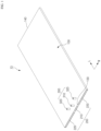
- FIG. 1 is a drawing illustrating a heat sink assembly according to one aspect of the present disclosure
- FIG. 2 is an exploded perspective view of the heat sink assembly of FIG. 1
- FIG. 3 is a drawing illustrating the structure of a heat sink in detail.
- the heat sink assembly 10 of aspects of the present disclosure includes a heat sink 100 manufactured by extrusion molding, and a plurality of end plugs 200.
- the open surfaces of the heat sink 100 are surfaces on both ends in a length direction L.
- the two open surfaces will be referred to as a first surface 130 and a second surface 140, respectively.
- the length direction L is defined as referring to the extrusion molding direction of the heat sink 100, in other words, the direction in which the plurality of flow paths 110 formed as hollow parts extend
- the width direction W is defined as referring to the direction in which the plurality of flow paths 110 are spaced apart and orthogonal to the length direction L on a plane.
- the heat sink 100 is manufactured as an extrusion in which a plurality of flow paths 110 are integrally molded along an length direction L by extrusion molding.
- the plurality of flow paths 110 in which the coolant flows are hollow parts formed along the length direction L, and the space between the flow paths 110 forms a solid part 120.
- the first surface 130 and the second surface 140 on both ends in the length direction L of the heat sink 100 are opened because of the features of the extrusion molding.
- FIG. 3 the structure of the flow path 110 is illustrated in more detail.
- a plurality of flow paths 110 extending in a length direction L between the first surface 130 and the second surface 140, the ends of which are separated from the first surface 130 and the second surface 140 by a predetermined distance.
- the separation distance of the flow paths 110 from the first surface 130 and the second surface 140 can be freely designed by a cutting processing that removes the flow paths 110, which are hollow parts, and the solid part 120 therebetween.
- a depth in which the end plugs 200 are to be inserted is obtained.
- the end plugs 200 close the opened first surface 130 and second surface 140 at both ends of the heat sink 100, respectively.
- the end plugs 200 have a thickness and width suitable for insertion into the openings on the first surface 130 and second surface 140 of the heat sink 100.
- the end plugs 200 inserted into the heat sink 100 may be sealed bonded by welding, for example, friction stir welding. If the welding depths of the friction stir welding performed on the upper and lower surfaces of the heat sink 100 are such that they overlap each other, a seal is completed by forming welding surfaces on up, down, left and right sides of the end plug 200.
- the heat sink assembly 10 can be configured to enable the flow of coolant across the overall heat transfer area of the heat sink assembly 10 by appropriately selecting the positions of the ports 300 through which the coolant flows in and out.
- the present disclosure includes an inlet port 310 through which coolant flows in and an outlet port 320 through which coolant flows out on the first surface 130, and the ports 300 are disposed such that the second surface 140 forms a return flow path 116 for coolant without separate ports.
- FIG. 4 is an enlarged view of "A" part of FIG. 1 , examined in conjunction with FIG. 3 , wherein an inlet flow path 112 connected to an inlet port 310 is disposed in a central region of the heat sink 100, a pair of outlet ports 320 are provided, and outlet flow paths 114 connected to the outlet ports 320 are disposed on both sides in the width direction W of the inlet flow path 112.
- two the inlet flow paths 112 are provided, and the terminals of the inlet flow path 112 are connected with a return flow path 116 elongated along the second surface 140, and the return flow path 116 is connected with the outlet flow paths 114 of both sides.
- the end plugs 200 closing the first surface 130 includes an inlet plug 210 closing the first surface 130 of the inlet flow path 112, and a pair of outlet plugs 220 closing the first surface 130 of the outlet flow path 114.
- a certain space is formed between the inlet plug 210 and the inlet flow path 112, and an inlet port 310 is disposed on this space. Accordingly, the coolant flowed in the inlet port 310 fills the space of the upstream side of the inlet flow path 112 and then diverges into each inlet flow path 112 and flows evenly.
- an outlet port 320 is disposed in the space between the outlet plug 220 and the outlet flow path 114.
- the cross-sectional area in the length direction L of the space between the inlet plug 210 and the inlet flow path 112 may be larger than the overall cross-sectional area in the length direction L of the inlet flow path 112.
- the space between the inlet plug 210 and the inlet flow path 112 forming reservoir space, the flow of coolant introduced into the plurality of inlet flow paths 112 may be uniform and smooth.
- FIG. 5 is an enlarged view of the "B" part of FIG. 1 , illustrating a return flow path 116.
- the second surface 140 of the heat sink 100 is closed with a return flow plug 230, and the terminal of each flow path 110, in other words, the end of each flow path 110 facing the second surface 140, is also separated from the return flow plug 230 by a predetermined separation distance, and the space thus formed forms the return flow path 116.
- the return flow path 116 may be formed by the flow paths 110 having a constant separation distance from the second surface 140, in other words, without substantial change in cross-sectional area.
- an end of each of the outlet flow paths 114 which directly connects to the outlet port 320, may be formed differently compared to the inlet flow path 112 or the return flow path 116.
- the plurality of outlet flow paths 114 may have a gradually decreasing separation distance from the first surface 130 as they become closer to the outlet port 320.
- the plurality of outlet flow paths 114 may have a linearly decreasing separation distance from the first surface 130 as they become closer to the outlet port 320.
- the outlet flow paths 114 near the center tend to have a concentration of coolant, which results in lower heat transfer performance in the peripheral regions. If the cooling performance of the heat sink assembly 10 varies according to the region, localized high heat regions are more likely to occur, which adversely affects the performance of the battery pack. Such deviation in cooling performance can be solved by inducing a uniform rate of flow of coolant through each of the outlet flow paths 114.
- FIG. 6 is a drawing illustrating overall coolant movement in the heat sink assembly of FIG. 1 .
- the plurality of outlet flow paths 114 has a shape such that the separation distance from the first surface 130 becomes gradually shorter as it becomes closer to the outlet port 320.
- the length of each of the plurality of outlet flow paths 114 becomes gradually longer as it becomes closer to the outlet port 320, in other words, as it becomes closer to the inlet flow path 112.
- the pressure loss acting on the coolant is proportional to the length of each outlet flow path 114 forming a boundary layer with the fluid.
- the heat sink assembly 10 enables the coolant to flow at a uniform rate of flow across the overall area of the heat sink 100, thereby exhibiting uniform cooling characteristics that are not concentrated in a particular region.
- FIG. 7 is a drawing illustrating one example of pack structures coupling to the heat sink assembly of FIG. 1 .
- an expanded solid part 122 is provided between the inlet flow path 112 and the outlet flow path 114 adjacent to the inlet flow path 112.
- the expanded solid part 122 refers to a solid part 122 having a larger width compared to, for example, the solid part 120 comprising the space between the flow paths 110.
- the expanded solid part 122 can be formed by forming a solid part with a width that skipped a space of about one flow path between the inlet flow path 112 and the outlet flow path 114.
- a flow path 110 is formed across nearly the entire of the heat sink 100, and therefore, in order to couple the heat sink assembly 10 of aspects of the present disclosure to the battery pack, it is necessary to provide a coupling structure capable of maintaining sufficient mechanical strength without damaging the flow path 110.
- an expanded solid part 122 is provided along the center length direction L of the heat sink assembly 10.
- a plurality of screw holes 124 may be processed along the expanded solid part 122, above which pack structures 400 (e.g., a center frame) may be firmly coupled to the heat sink assembly 10 by bolts 410 that are engaged to the screw holes 124.
- pack structures 400 e.g., a center frame
- FIG. 8 is a drawing illustrating an aspect of a pair of outlet ports interconnected by a pipe member.
- the present disclosure comprises two outlet ports 320 in the flow path structure. Therefore, two external pipes connecting to the outlet ports 320 are needed, but by connecting the pair of outlet ports 320 with the pipe member 330 in the shape of the letter "Y" or "T", as shown in FIG. 8 , the coolant flowing in two streams can be joined into one. By the pipe member 330 joining the two outlet ports 320 into one, the external pipe structure comprising the heat sink assembly 10 is more simplified.
Landscapes
- Engineering & Computer Science (AREA)
- Manufacturing & Machinery (AREA)
- Chemical & Material Sciences (AREA)
- Chemical Kinetics & Catalysis (AREA)
- Electrochemistry (AREA)
- General Chemical & Material Sciences (AREA)
- Physics & Mathematics (AREA)
- Thermal Sciences (AREA)
- Mechanical Engineering (AREA)
- General Engineering & Computer Science (AREA)
- Geometry (AREA)
- Cooling Or The Like Of Semiconductors Or Solid State Devices (AREA)
- Secondary Cells (AREA)
Abstract
Description
- The present application is a 371 National Stage entry of
PCT/KR2024/007360 filed May 30, 2024 Korean Patent Application No. 10-2023-0071942, filed on June 02, 2023 - The present disclosure relates to a heat sink assembly mounted to a bottom surface of a battery pack having a plurality of secondary batteries to facilitate heat dissipation of the battery pack.
- Secondary batteries, unlike primary batteries, are rechargeable and have been widely researched and developed in recent years due to the potential for miniaturization and large capacity. The demand for secondary batteries as an energy source is increasing rapidly due to the increasing technological development and demand for mobile devices, as well as electric vehicles and energy storage systems that are emerging in response to environmental protection needs.
- Secondary batteries are categorized into coin type batteries, cylindrical batteries, prismatic batteries, and pouch type batteries according to the shape of the battery case. In a secondary battery, an electrode assembly mounted inside the battery case is a chargeable and dischargeable power generating device comprising a stacked structure of electrodes and separators.
- Since secondary batteries are demanded to be used continuously for a long period of time, it is necessary to effectively control the heat generated during the charging and discharging process. If the secondary battery is not properly cooled, the increase in temperature will cause an increase in current, which will cause an increase in current, which will again cause an increase in temperature, which will cause a chain reaction, eventually leading to the catastrophic condition of thermal runaway.
- In order to effectively release the heat generated by secondary batteries, heat sinks (also called cooling plates) through which coolant flows are widely used. The heat sink is mounted on the bottom surface of a group of secondary batteries, such as a battery pack mounting a plurality of secondary batteries and performs a cooling function by absorbing heat generated inside the pack with a coolant and releasing it to the outside.
- Heat sinks can be divided into brazing heat sinks and extruded heat sinks according to their structure or manufacturing method. A brazing heat sink is a structure in which two plates are brazed together to form a flow path, which has a high degree of freedom in flow path design but has a disadvantage in structural rigidity due to material degradation. On the other hand, extruded heat sinks, which are manufactured as a continuum through extrusion molding, have an advantage in structural rigidity, but have the disadvantage that only straight flow paths can be realized, resulting in a large number of ports, and thus, pipes for connection take up space.
- The present disclosure is directed to providing a heat sink assembly that is an extruded heat sink and does not require a separate pipe for flow path formation, thereby occupying less space, and can improve differential pressure by reducing the number of components with a simplified flow path configuration, and uniformly inducing a rate of flow of coolant flowing in a plurality of flow paths.
- However, the technical problem to be solved by the present disclosure is not limited to the above-described problem, and other problems not mentioned can be clearly understood by a person skilled in the art from the description of the disclosure described below.
- The present disclosure relates to a heat sink assembly includes a heat sink having a plurality of flow paths are integrally molded along an length direction by extrusion molding, the spaces between the flow paths forming a solid part, a first surface and a second surface of both ends in the length direction are opened, and both ends of the flow paths are spaced apart from the first surface and the second surface, and end plugs closing the opened first surface and second surface of both ends of the heat sink, respectively, wherein the first surface is disposed with an inlet port through which the coolant flows in and an outlet port through which the coolant flows out, and the second surface forms a return flow path of the coolant.
- In one aspect of the present disclosure, an inlet flow path connected to the inlet port is disposed in a central region of the heat sink, and a pair of the outlet ports are provided such that the outlet flow paths connected to the outlet ports may be disposed on both sides of the inlet flow path.
- The end plug may comprise an inlet plug closing a first surface of the inlet flow path, a pair of outlet plugs closing a first surface of the outlet flow path, and a return flow plug closing a second surface of the return flow path.
- Meanwhile, the plurality of outlet flow paths may have a separation distance from the first surface that gradually decreases as the plurality of the outlet flow paths becomes closer to the inlet port.
- For example, the plurality of outlet flow paths may have a separation distance from the first surface that decreases linearly as the plurality of outlet flow paths becomes closer to the outlet port.
- The return flow path may have a constant separation distance from the second surface.
- The plurality of outlet flow paths, wherein the pressure loss acting on the coolant flowing through the return flow path of the second surface to each of the plurality of outlet flow paths is proportional to the overall length of the outlet flow path, thereby uniformizing the rate of flow of the coolant flowing in each of the outlet flow paths.
- In addition, in some aspects, an expanded solid part may be provided between the inlet flow path and the outlet flow path adjacent to the inlet flow path.
- In the expanded solid part, the pack structures may be mechanically coupled.
- In addition, a cross-sectional area in the length direction of the space between the inlet plug and the inlet flow path may be larger than a cross-sectional area in the length direction of the inlet flow path.
- Further, the coolant flowing out from each of the pair of outlet ports may be joined into one by a pipe member.
- The heat sink assembly of aspects of the present disclosure, having the configuration as described above, has excellent structural rigidity because the heat sink is manufactured as a continuum by extrusion molding, meanwhile, it can comprise a cooling passage divided into an inlet and an outlet by performing machining processing on both ends in the length direction of the flow path integrally formed in the heat sink and closing the open surface with an end plug.
- Accordingly, the heat sink assembly of aspects of the present disclosure, while having an extruded heat sink as a basic framework which is advantageous in structural rigidity, occupies less space by not requiring a separate pipe for forming the flow path, can improve the differential pressure by reducing the number of components with a simplified flow path configuration, and can obtain stable cooling performance throughout the overall heat dissipating area by uniformly inducing the rate of flow of the coolant flowing in the plurality of flow paths.
- However, the technical effects that can be obtained through the present disclosure is not limited to the above-described effects, and other effects not mentioned can be clearly understood by a person skilled in the art from the description of the disclosure described below.
- Because the following drawings attached to the present specification illustrate exemplary aspects of the present disclosure and serve to facilitate understanding of the technical idea of the present disclosure together with the detailed description of the disclosure described below, the present disclosure should not be limitedly interpreted on the basis of the drawings.
-
FIG. 1 is a drawing illustrating a heat sink assembly according to one aspect of the present disclosure. -
FIG. 2 is an exploded perspective view of the heat sink assembly ofFIG. 1 . -
FIG. 3 is a drawing illustrating the structure of a heat sink in detail. -
FIG. 4 is an enlarged view of "A" part ofFIG. 1 . -
FIG. 5 is an enlarged view of the "B" part ofFIG. 1 . -
FIG. 6 is a drawing illustrating overall coolant movement in the heat sink assembly ofFIG. 1 . -
FIG. 7 is a drawing illustrating one example of pack structures coupling to the heat sink assembly ofFIG. 1 . -
FIG. 8 is a drawing illustrating an aspect of a pair of outlet ports interconnected by a pipe member. - References characters used in the present disclosure are as follows:
- 10: heat sink assembly
- 100: heat sink
- 110: flow path
- 112: inlet flow path
- 114: outlet flow path
- 116: return flow path
- 120: solid part
- 122: expanded solid part
- 124: screw hole
- 130: first surface
- 140: second surface
- 200: end plug
- 210: inlet plug
- 220: outlet plug
- 230: return flow plug
- 300: port
- 310: inlet port
- 320: outlet port
- 330: pipe member
- 400: pack structures
- 410: bolt
- L: length direction
- W: width direction
- The present disclosure may have various modifications and various aspects, and thus specific aspects thereof will be described in detail below.
- However, it should be understood that the present disclosure is not limited to the specific aspects, and includes all modifications, equivalents, or alternatives within the spirit and technical scope of the present disclosure.
- The terms "comprise," "include," and "have" used herein designate the presence of characteristics, numbers, steps, actions, components, or members described in the specification or a combination thereof, and it should be understood that the possibility of the presence or addition of one or more other characteristics, numbers, steps, actions, components, members, or a combination thereof is not excluded in advance.
- In addition, in the present disclosure, when a part of a layer, film, region, plate, or the like is disposed "on" another part, this includes not only a case in which one part is disposed "directly on" another part, but a case in which still another part is interposed therebetween. In contrast, when a part of a layer, film, region, plate, or the like is disposed "under" another part, this includes not only a case in which one part is disposed "directly under" another part, but a case in which still another part is interposed therebetween. In addition, in the present application, "on" may include not only a case of being disposed on an upper portion but also a case of being disposed on a lower portion.
- The present disclosure relates to a heat sink assembly includes a heat sink having a plurality of flow paths are integrally molded along an length direction by extrusion molding, the spaces between the flow paths forming a solid part, a first surface and a second surface of both ends in the length direction are opened, and both ends of the flow paths are spaced apart from the first surface and the second surface, and end plugs closing the opened first surface and second surface of both ends of the heat sink, respectively, wherein the first surface is disposed with an inlet port through which the coolant flows in and an outlet port through which the coolant flows out, and the second surface forms a return flow path of the coolant.
- The heat sink assembly of aspects of the present disclosure having the above configuration is manufactured as a continuum by extrusion molding to possess excellent structural rigidity, meanwhile, and comprise a cooling passage divided into an inlet and an outlet by performing machining processing on both ends in the length direction of the flow path integrally formed in the heat sink and closing the open surface with an end plug.
- Accordingly, the heat sink assembly of aspects of the present disclosure, while having an extruded heat sink as a basic framework which is advantageous in structural rigidity, occupies less space by not requiring a separate pipe for forming the flow path, can improve differential pressure by reducing the number of components with a simplified flow path configuration.
- Hereinafter, specific aspects of a
heat sink assembly 10 according to the present disclosure will be described in detail with reference to the accompanying drawings. For reference, the directions of front, back, up, down, left, and right used in the following description to designate relative positions are for the purpose of understanding the disclosure and refer to the directions shown in the drawings unless otherwise specified. -
FIG. 1 is a drawing illustrating a heat sink assembly according to one aspect of the present disclosure,FIG. 2 is an exploded perspective view of the heat sink assembly ofFIG. 1 , andFIG. 3 is a drawing illustrating the structure of a heat sink in detail. - The
heat sink assembly 10 of aspects of the present disclosure includes aheat sink 100 manufactured by extrusion molding, and a plurality of end plugs 200. The open surfaces of theheat sink 100 are surfaces on both ends in a length direction L. For ease of description, the two open surfaces will be referred to as afirst surface 130 and asecond surface 140, respectively. Here, the length direction L is defined as referring to the extrusion molding direction of theheat sink 100, in other words, the direction in which the plurality offlow paths 110 formed as hollow parts extend, and the width direction W is defined as referring to the direction in which the plurality offlow paths 110 are spaced apart and orthogonal to the length direction L on a plane. - The
heat sink 100 is manufactured as an extrusion in which a plurality offlow paths 110 are integrally molded along an length direction L by extrusion molding. The plurality offlow paths 110 in which the coolant flows are hollow parts formed along the length direction L, and the space between theflow paths 110 forms asolid part 120. Thefirst surface 130 and thesecond surface 140 on both ends in the length direction L of theheat sink 100 are opened because of the features of the extrusion molding. - In
FIG. 3 , the structure of theflow path 110 is illustrated in more detail. A plurality offlow paths 110 extending in a length direction L between thefirst surface 130 and thesecond surface 140, the ends of which are separated from thefirst surface 130 and thesecond surface 140 by a predetermined distance. The separation distance of theflow paths 110 from thefirst surface 130 and thesecond surface 140 can be freely designed by a cutting processing that removes theflow paths 110, which are hollow parts, and thesolid part 120 therebetween. In addition, by removing theflow path 110 and thesolid part 120 therebetween together, a depth in which the end plugs 200 are to be inserted is obtained. - The end plugs 200 close the opened
first surface 130 andsecond surface 140 at both ends of theheat sink 100, respectively. The end plugs 200 have a thickness and width suitable for insertion into the openings on thefirst surface 130 andsecond surface 140 of theheat sink 100. The end plugs 200 inserted into theheat sink 100 may be sealed bonded by welding, for example, friction stir welding. If the welding depths of the friction stir welding performed on the upper and lower surfaces of theheat sink 100 are such that they overlap each other, a seal is completed by forming welding surfaces on up, down, left and right sides of theend plug 200. - Since the plurality of
flow paths 110 extend in the length direction L, and thefirst surface 130 andsecond surface 140 are sealed with end plugs 200, theheat sink assembly 10 can be configured to enable the flow of coolant across the overall heat transfer area of theheat sink assembly 10 by appropriately selecting the positions of theports 300 through which the coolant flows in and out. The present disclosure includes aninlet port 310 through which coolant flows in and anoutlet port 320 through which coolant flows out on thefirst surface 130, and theports 300 are disposed such that thesecond surface 140 forms areturn flow path 116 for coolant without separate ports. -
FIG. 4 is an enlarged view of "A" part ofFIG. 1 , examined in conjunction withFIG. 3 , wherein aninlet flow path 112 connected to aninlet port 310 is disposed in a central region of theheat sink 100, a pair ofoutlet ports 320 are provided, andoutlet flow paths 114 connected to theoutlet ports 320 are disposed on both sides in the width direction W of theinlet flow path 112. In the illustrated aspect, two theinlet flow paths 112 are provided, and the terminals of theinlet flow path 112 are connected with areturn flow path 116 elongated along thesecond surface 140, and thereturn flow path 116 is connected with theoutlet flow paths 114 of both sides. - In one aspect of the present disclosure, the end plugs 200 closing the
first surface 130 includes aninlet plug 210 closing thefirst surface 130 of theinlet flow path 112, and a pair of outlet plugs 220 closing thefirst surface 130 of theoutlet flow path 114. A certain space is formed between theinlet plug 210 and theinlet flow path 112, and aninlet port 310 is disposed on this space. Accordingly, the coolant flowed in theinlet port 310 fills the space of the upstream side of theinlet flow path 112 and then diverges into eachinlet flow path 112 and flows evenly. Similarly, anoutlet port 320 is disposed in the space between theoutlet plug 220 and theoutlet flow path 114. - Moreover, the cross-sectional area in the length direction L of the space between the
inlet plug 210 and theinlet flow path 112 may be larger than the overall cross-sectional area in the length direction L of theinlet flow path 112. The space between theinlet plug 210 and theinlet flow path 112 forming reservoir space, the flow of coolant introduced into the plurality ofinlet flow paths 112 may be uniform and smooth. -
FIG. 5 is an enlarged view of the "B" part ofFIG. 1 , illustrating areturn flow path 116. Thesecond surface 140 of theheat sink 100 is closed with areturn flow plug 230, and the terminal of eachflow path 110, in other words, the end of eachflow path 110 facing thesecond surface 140, is also separated from thereturn flow plug 230 by a predetermined separation distance, and the space thus formed forms thereturn flow path 116. Thereturn flow path 116 may be formed by theflow paths 110 having a constant separation distance from thesecond surface 140, in other words, without substantial change in cross-sectional area. - On the other hand, in one of the of the present disclosure, an end of each of the
outlet flow paths 114, which directly connects to theoutlet port 320, may be formed differently compared to theinlet flow path 112 or thereturn flow path 116. As illustrated inFIGS. 3 and4 , the plurality ofoutlet flow paths 114 may have a gradually decreasing separation distance from thefirst surface 130 as they become closer to theoutlet port 320. For example, the plurality ofoutlet flow paths 114 may have a linearly decreasing separation distance from thefirst surface 130 as they become closer to theoutlet port 320. - The
heat sink assembly 10 of aspects of the present disclosure has an excessively large flow area occupied by theoutlet flow path 114 compared to the flow area formed by theinlet flow path 112 and thereturn flow path 116. This is for the purpose that when the coolant is flowed in theheat sink 100, the flow velocity of theoutlet flow path 114 is significantly reduced so that heat can be transferred for a sufficient time. On a different aspect, the flow rate distribution of the coolant is also most influenced by theoutlet flow path 114 - Because of the characteristics of the flow, the closer the
outlet flow path 114 is to theinlet flow path 112, the lower the pressure loss until the coolant is flowed in, and because of this, the closer theoutlet flow path 114 is to theinlet flow path 112, the more coolant tends to be introduced. Thus, in the illustratedheat sink assembly 10, theoutlet flow paths 114 near the center tend to have a concentration of coolant, which results in lower heat transfer performance in the peripheral regions. If the cooling performance of theheat sink assembly 10 varies according to the region, localized high heat regions are more likely to occur, which adversely affects the performance of the battery pack. Such deviation in cooling performance can be solved by inducing a uniform rate of flow of coolant through each of theoutlet flow paths 114. -
FIG. 6 is a drawing illustrating overall coolant movement in the heat sink assembly ofFIG. 1 . As described above, the plurality ofoutlet flow paths 114 has a shape such that the separation distance from thefirst surface 130 becomes gradually shorter as it becomes closer to theoutlet port 320. In other words, the length of each of the plurality ofoutlet flow paths 114 becomes gradually longer as it becomes closer to theoutlet port 320, in other words, as it becomes closer to theinlet flow path 112. In eachoutlet flow path 114, the pressure loss acting on the coolant is proportional to the length of eachoutlet flow path 114 forming a boundary layer with the fluid. Thus, since the pressure loss acting on the coolant flowing through thereturn flow path 116 of thesecond surface 140 into eachoutlet flow path 114 is proportional to the overall length of theoutlet flow path 114, the rate of flow of the coolant gradually increases toward theoutlet flow path 114 on the outer side surface, and as a result, when theoutlet flow path 114 is closer to theinlet flow path 112, the characteristics of more coolant being introduced are offset, resulting in a uniform rate of flow of the coolant flowing through eachoutlet flow path 114. - As described above, the
heat sink assembly 10 according to an aspect of the present disclosure enables the coolant to flow at a uniform rate of flow across the overall area of theheat sink 100, thereby exhibiting uniform cooling characteristics that are not concentrated in a particular region. -
FIG. 7 is a drawing illustrating one example of pack structures coupling to the heat sink assembly ofFIG. 1 . Referring toFIGS. 1 to 5 together, an expandedsolid part 122 is provided between theinlet flow path 112 and theoutlet flow path 114 adjacent to theinlet flow path 112. Here, the expandedsolid part 122 refers to asolid part 122 having a larger width compared to, for example, thesolid part 120 comprising the space between theflow paths 110. For example, the expandedsolid part 122 can be formed by forming a solid part with a width that skipped a space of about one flow path between theinlet flow path 112 and theoutlet flow path 114. - As illustrated in
FIG. 3 andFIG. 6 , aflow path 110 is formed across nearly the entire of theheat sink 100, and therefore, in order to couple theheat sink assembly 10 of aspects of the present disclosure to the battery pack, it is necessary to provide a coupling structure capable of maintaining sufficient mechanical strength without damaging theflow path 110. For this, an expandedsolid part 122 is provided along the center length direction L of theheat sink assembly 10. - For example, as shown in
FIG. 7 , a plurality of screw holes 124 may be processed along the expandedsolid part 122, above which pack structures 400 (e.g., a center frame) may be firmly coupled to theheat sink assembly 10 bybolts 410 that are engaged to the screw holes 124. -
FIG. 8 is a drawing illustrating an aspect of a pair of outlet ports interconnected by a pipe member. - The present disclosure comprises two
outlet ports 320 in the flow path structure. Therefore, two external pipes connecting to theoutlet ports 320 are needed, but by connecting the pair ofoutlet ports 320 with thepipe member 330 in the shape of the letter "Y" or "T", as shown inFIG. 8 , the coolant flowing in two streams can be joined into one. By thepipe member 330 joining the twooutlet ports 320 into one, the external pipe structure comprising theheat sink assembly 10 is more simplified. - As aforementioned, the present disclosure has been described in more detail through the drawings and aspects. However, since the configuration described in the drawings or aspects described herein is merely one aspect of the present disclosure and do not represent the overall technical spirit of the disclosure, it should be understood that the disclosure covers various equivalents, modifications, and substitutions at the time of filing of this application.
Claims (11)
- A heat sink assembly comprising: a heat sink having a plurality of flow paths integrally formed along an length direction, spaces between the plurality of flow paths forming a solid part, a first surface and a second surface of both ends in the length direction are opened, and both ends of the plurality of flow paths are spaced apart from the first surface and the second surface; andend plugs closing the opened first surface and second surface of both ends of the heat sink, respectively,wherein the first surface is disposed adjacent an inlet port configured to received coolant flow in and an outlet port configured for coolant flow out,wherein the second surface forms a return flow path for coolant.
- The heat sink assembly of claim 1, wherein the plurality of flow paths comprise an inlet flow paths and a plurality of outlet flow paths,the inlet flow path is connected to the inlet port and disposed in a central region of the heat sink,and the outlet port is one of a pair of outlet ports provided such that the plurality of outlet flow paths connected to the pair of outlet ports are disposed on both sides of the inlet flow path.
- The heat sink assembly of claim 2, wherein the end plugs includes an inlet plug closing the first surface having the inlet flow path,a pair of outlet plugs closing the first surface having the plurality of outlet flow paths, anda return flow plug closing the second surface having the return flow path.
- The heat sink assembly of claim 2, wherein the plurality of outlet flow paths has a separation distance from the first surface that gradually decreases as the plurality of the outlet flow paths becomes closer to the outlet port.
- The heat sink assembly of claim 4, wherein the plurality of outlet flow paths has a separation distance from the first surface that decreases linearly as the plurality of outlet flow paths becomes closer to the outlet port.
- The heat sink assembly of claim 4, wherein the return flow path has a constant separation distance from the second surface.
- The heat sink assembly of claim 6, wherein pressure loss acting on coolant flowing through the return flow path of the second surface to each of the plurality of outlet flow paths is proportional to the overall length of the outlet flow path.
- The heat sink assembly of claim 2, wherein an expanded solid part is provided between the inlet flow path and the outlet flow path adjacent to the inlet flow path.
- The heat sink assembly of claim 8, wherein in the expanded solid part is configured to mechanically couple to pack structures.
- The heat sink assembly of claim 3, wherein a cross-sectional area in the length direction of a space between the inlet plug and the inlet flow path is larger than a cross-sectional area in the length direction of the inlet flow path.
- The heat sink assembly of claim 2, further comprising a pipe member, wherein coolant flowing out from each of the pair of outlet ports is joined into one by the pipe member.
Applications Claiming Priority (2)
| Application Number | Priority Date | Filing Date | Title |
|---|---|---|---|
| KR1020230071942A KR20240173083A (en) | 2023-06-02 | 2023-06-02 | Heat sink assembly |
| PCT/KR2024/007360 WO2024248488A1 (en) | 2023-06-02 | 2024-05-30 | Heat sink assembly |
Publications (2)
| Publication Number | Publication Date |
|---|---|
| EP4567971A1 true EP4567971A1 (en) | 2025-06-11 |
| EP4567971A4 EP4567971A4 (en) | 2026-02-11 |
Family
ID=93658286
Family Applications (1)
| Application Number | Title | Priority Date | Filing Date |
|---|---|---|---|
| EP24815863.6A Pending EP4567971A4 (en) | 2023-06-02 | 2024-05-30 | HEATSOCKET ARRANGEMENT |
Country Status (5)
| Country | Link |
|---|---|
| EP (1) | EP4567971A4 (en) |
| JP (1) | JP2025528274A (en) |
| KR (1) | KR20240173083A (en) |
| CN (1) | CN119816987A (en) |
| WO (1) | WO2024248488A1 (en) |
Family Cites Families (14)
| Publication number | Priority date | Publication date | Assignee | Title |
|---|---|---|---|---|
| JP4819071B2 (en) * | 2008-02-06 | 2011-11-16 | 本田技研工業株式会社 | Electric vehicle and cooling method for DC / DC converter for vehicle |
| JP2009272137A (en) * | 2008-05-07 | 2009-11-19 | Calsonic Kansei Corp | Heat exchanger |
| KR101431550B1 (en) * | 2012-07-03 | 2014-10-06 | (주)인벤티오 | Apparatus for cooling battery and method of producing the same |
| KR20140026961A (en) * | 2012-08-24 | 2014-03-06 | 주식회사 한국쿨러 | Heat exchanger for battery |
| JP2014216298A (en) * | 2013-04-30 | 2014-11-17 | 日立オートモティブシステムズ株式会社 | Battery module |
| KR101589935B1 (en) * | 2014-01-06 | 2016-01-29 | 희성정밀 주식회사 | Battery cooling apparatus for electric vehicle and manufacturing method thereof |
| KR101619449B1 (en) * | 2014-10-24 | 2016-05-10 | 주식회사 고산 | Extrusion type heat exchanger for battery |
| CN204809357U (en) * | 2015-07-27 | 2015-11-25 | 宁德时代新能源科技有限公司 | Hot management component of group battery |
| CN106654456A (en) * | 2017-02-20 | 2017-05-10 | 东莞市迈泰热传科技有限公司 | Water cooling plate structure of new energy automobile |
| KR101750029B1 (en) * | 2017-02-24 | 2017-06-23 | 엠에이치기술개발 주식회사 | Cooling apparatus for battery and manufacturing method of the same |
| KR102378425B1 (en) * | 2017-06-07 | 2022-03-24 | 삼성에스디아이 주식회사 | Battery pack |
| CN109546263B (en) * | 2018-12-03 | 2023-09-08 | 清华大学苏州汽车研究院(相城) | Water cooling plate mechanism and water cooling plate processing technology |
| KR102228616B1 (en) | 2019-02-13 | 2021-03-16 | 주식회사 세광정밀 | Water-cooled battery pack cooling device to reduce working fluid flow resistance |
| CN214477762U (en) * | 2021-04-22 | 2021-10-22 | 远景动力技术(江苏)有限公司 | A liquid-cooled integrated box |
-
2023
- 2023-06-02 KR KR1020230071942A patent/KR20240173083A/en active Pending
-
2024
- 2024-05-30 CN CN202480003870.6A patent/CN119816987A/en active Pending
- 2024-05-30 JP JP2025513430A patent/JP2025528274A/en active Pending
- 2024-05-30 EP EP24815863.6A patent/EP4567971A4/en active Pending
- 2024-05-30 WO PCT/KR2024/007360 patent/WO2024248488A1/en not_active Ceased
Also Published As
| Publication number | Publication date |
|---|---|
| KR20240173083A (en) | 2024-12-10 |
| CN119816987A (en) | 2025-04-11 |
| EP4567971A4 (en) | 2026-02-11 |
| WO2024248488A1 (en) | 2024-12-05 |
| JP2025528274A (en) | 2025-08-26 |
Similar Documents
| Publication | Publication Date | Title |
|---|---|---|
| JP7027641B2 (en) | A cooling jacket with a non-uniform flow path for cooling the surface of the battery cell and a battery module containing it. | |
| CN104218274B (en) | Battery pack | |
| JP2024084852A (en) | Cold plate vanes for battery modules | |
| US10797366B2 (en) | Temperature-controlling device for a battery module, method for manufacturing same and battery module | |
| CN110024211A (en) | Cartridge for battery cell and battery module including the same | |
| CN115621646A (en) | Battery and method for manufacturing battery | |
| EP4567971A1 (en) | Heat sink assembly | |
| EP4593160A1 (en) | Heat sink assembly | |
| EP4553957A1 (en) | Heat sink assembly | |
| EP4601083A1 (en) | Heat sink assembly | |
| US20260058246A1 (en) | Heat Sink Assembly | |
| CN104124493A (en) | Battery | |
| EP4571945A1 (en) | Heat sink assembly | |
| KR102862698B1 (en) | Heat sink assembly | |
| CN222233722U (en) | Battery Pack | |
| EP4718599A1 (en) | Extruded pack housing and manufacturing method thereof | |
| JP2025167794A (en) | heat sink | |
| KR20240173892A (en) | Heat sink assembly | |
| CN121748622A (en) | Battery pack and electric equipment with same |
Legal Events
| Date | Code | Title | Description |
|---|---|---|---|
| STAA | Information on the status of an ep patent application or granted ep patent |
Free format text: STATUS: THE INTERNATIONAL PUBLICATION HAS BEEN MADE |
|
| PUAI | Public reference made under article 153(3) epc to a published international application that has entered the european phase |
Free format text: ORIGINAL CODE: 0009012 |
|
| STAA | Information on the status of an ep patent application or granted ep patent |
Free format text: STATUS: REQUEST FOR EXAMINATION WAS MADE |
|
| 17P | Request for examination filed |
Effective date: 20250304 |
|
| AK | Designated contracting states |
Kind code of ref document: A1 Designated state(s): AL AT BE BG CH CY CZ DE DK EE ES FI FR GB GR HR HU IE IS IT LI LT LU LV MC ME MK MT NL NO PL PT RO RS SE SI SK SM TR |
|
| A4 | Supplementary search report drawn up and despatched |
Effective date: 20260113 |
|
| RIC1 | Information provided on ipc code assigned before grant |
Ipc: H01M 10/6556 20140101AFI20260107BHEP Ipc: H01M 10/6554 20140101ALI20260107BHEP Ipc: H01M 10/613 20140101ALI20260107BHEP Ipc: F28D 1/03 20060101ALI20260107BHEP Ipc: F28F 1/02 20060101ALI20260107BHEP Ipc: F28F 3/12 20060101ALI20260107BHEP Ipc: H01M 10/625 20140101ALI20260107BHEP Ipc: H01M 10/6567 20140101ALI20260107BHEP |