EP4567506A1 - Backlight module and display device - Google Patents
Backlight module and display device Download PDFInfo
- Publication number
- EP4567506A1 EP4567506A1 EP22956315.0A EP22956315A EP4567506A1 EP 4567506 A1 EP4567506 A1 EP 4567506A1 EP 22956315 A EP22956315 A EP 22956315A EP 4567506 A1 EP4567506 A1 EP 4567506A1
- Authority
- EP
- European Patent Office
- Prior art keywords
- framework
- backlight module
- plate
- light plate
- light
- Prior art date
- Legal status (The legal status is an assumption and is not a legal conclusion. Google has not performed a legal analysis and makes no representation as to the accuracy of the status listed.)
- Pending
Links
Images


Classifications
-
- G—PHYSICS
- G02—OPTICS
- G02F—OPTICAL DEVICES OR ARRANGEMENTS FOR THE CONTROL OF LIGHT BY MODIFICATION OF THE OPTICAL PROPERTIES OF THE MEDIA OF THE ELEMENTS INVOLVED THEREIN; NON-LINEAR OPTICS; FREQUENCY-CHANGING OF LIGHT; OPTICAL LOGIC ELEMENTS; OPTICAL ANALOGUE/DIGITAL CONVERTERS
- G02F1/00—Devices or arrangements for the control of the intensity, colour, phase, polarisation or direction of light arriving from an independent light source, e.g. switching, gating or modulating; Non-linear optics
- G02F1/01—Devices or arrangements for the control of the intensity, colour, phase, polarisation or direction of light arriving from an independent light source, e.g. switching, gating or modulating; Non-linear optics for the control of the intensity, phase, polarisation or colour
- G02F1/13—Devices or arrangements for the control of the intensity, colour, phase, polarisation or direction of light arriving from an independent light source, e.g. switching, gating or modulating; Non-linear optics for the control of the intensity, phase, polarisation or colour based on liquid crystals, e.g. single liquid crystal display cells
- G02F1/133—Constructional arrangements; Operation of liquid crystal cells; Circuit arrangements
- G02F1/1333—Constructional arrangements; Manufacturing methods
- G02F1/133308—Support structures for LCD panels, e.g. frames or bezels
-
- G—PHYSICS
- G02—OPTICS
- G02F—OPTICAL DEVICES OR ARRANGEMENTS FOR THE CONTROL OF LIGHT BY MODIFICATION OF THE OPTICAL PROPERTIES OF THE MEDIA OF THE ELEMENTS INVOLVED THEREIN; NON-LINEAR OPTICS; FREQUENCY-CHANGING OF LIGHT; OPTICAL LOGIC ELEMENTS; OPTICAL ANALOGUE/DIGITAL CONVERTERS
- G02F1/00—Devices or arrangements for the control of the intensity, colour, phase, polarisation or direction of light arriving from an independent light source, e.g. switching, gating or modulating; Non-linear optics
- G02F1/01—Devices or arrangements for the control of the intensity, colour, phase, polarisation or direction of light arriving from an independent light source, e.g. switching, gating or modulating; Non-linear optics for the control of the intensity, phase, polarisation or colour
- G02F1/13—Devices or arrangements for the control of the intensity, colour, phase, polarisation or direction of light arriving from an independent light source, e.g. switching, gating or modulating; Non-linear optics for the control of the intensity, phase, polarisation or colour based on liquid crystals, e.g. single liquid crystal display cells
- G02F1/133—Constructional arrangements; Operation of liquid crystal cells; Circuit arrangements
- G02F1/1333—Constructional arrangements; Manufacturing methods
- G02F1/1335—Structural association of cells with optical devices, e.g. polarisers or reflectors
- G02F1/1336—Illuminating devices
- G02F1/133602—Direct backlight
- G02F1/133603—Direct backlight with LEDs
-
- G—PHYSICS
- G02—OPTICS
- G02F—OPTICAL DEVICES OR ARRANGEMENTS FOR THE CONTROL OF LIGHT BY MODIFICATION OF THE OPTICAL PROPERTIES OF THE MEDIA OF THE ELEMENTS INVOLVED THEREIN; NON-LINEAR OPTICS; FREQUENCY-CHANGING OF LIGHT; OPTICAL LOGIC ELEMENTS; OPTICAL ANALOGUE/DIGITAL CONVERTERS
- G02F1/00—Devices or arrangements for the control of the intensity, colour, phase, polarisation or direction of light arriving from an independent light source, e.g. switching, gating or modulating; Non-linear optics
- G02F1/01—Devices or arrangements for the control of the intensity, colour, phase, polarisation or direction of light arriving from an independent light source, e.g. switching, gating or modulating; Non-linear optics for the control of the intensity, phase, polarisation or colour
- G02F1/13—Devices or arrangements for the control of the intensity, colour, phase, polarisation or direction of light arriving from an independent light source, e.g. switching, gating or modulating; Non-linear optics for the control of the intensity, phase, polarisation or colour based on liquid crystals, e.g. single liquid crystal display cells
- G02F1/133—Constructional arrangements; Operation of liquid crystal cells; Circuit arrangements
- G02F1/1333—Constructional arrangements; Manufacturing methods
- G02F1/1335—Structural association of cells with optical devices, e.g. polarisers or reflectors
- G02F1/1336—Illuminating devices
- G02F1/133602—Direct backlight
- G02F1/133608—Direct backlight including particular frames or supporting means
-
- G—PHYSICS
- G02—OPTICS
- G02F—OPTICAL DEVICES OR ARRANGEMENTS FOR THE CONTROL OF LIGHT BY MODIFICATION OF THE OPTICAL PROPERTIES OF THE MEDIA OF THE ELEMENTS INVOLVED THEREIN; NON-LINEAR OPTICS; FREQUENCY-CHANGING OF LIGHT; OPTICAL LOGIC ELEMENTS; OPTICAL ANALOGUE/DIGITAL CONVERTERS
- G02F1/00—Devices or arrangements for the control of the intensity, colour, phase, polarisation or direction of light arriving from an independent light source, e.g. switching, gating or modulating; Non-linear optics
- G02F1/01—Devices or arrangements for the control of the intensity, colour, phase, polarisation or direction of light arriving from an independent light source, e.g. switching, gating or modulating; Non-linear optics for the control of the intensity, phase, polarisation or colour
- G02F1/13—Devices or arrangements for the control of the intensity, colour, phase, polarisation or direction of light arriving from an independent light source, e.g. switching, gating or modulating; Non-linear optics for the control of the intensity, phase, polarisation or colour based on liquid crystals, e.g. single liquid crystal display cells
- G02F1/133—Constructional arrangements; Operation of liquid crystal cells; Circuit arrangements
- G02F1/1333—Constructional arrangements; Manufacturing methods
- G02F1/1335—Structural association of cells with optical devices, e.g. polarisers or reflectors
- G02F1/1336—Illuminating devices
- G02F1/133628—Illuminating devices with cooling means
Definitions
- the present invention relates to the field of display technology, and more particularly relates to a backlight module and a display device.
- Liquid crystal display has undergone many years of development, and so the technology is relatively mature.
- screen manufacturers are also actively responding to these demands, striving to produce more competitive products.
- Displays using Mini LED can achieve better overall ultra-thinness, high dynamic range (HDR) imaging performance, higher contrast, more partitions, and low power consumption.
- Their display effect is comparable to that of OLED (Organic Light Emitting Diode), bringing consumers a very high viewing experience and bringing more diverse display consumption choices to the market.
- the backlight module includes a framework, at least one light plate and a plurality of lamp beads.
- the framework includes at least one light plate mounting groove. At least two sides of the framework corresponding to the mounting groove of the light plate define heat dissipation ports, and the heat dissipation ports go through the side walls of the framework.
- the light plates are arranged in one-to-one correspondence with the light plate mounting grooves, and are fixed in the light plate mounting grooves.
- the interior of each light plate is hollowed out to form a cavity, and the cavity communicates with the heat dissipation port in the framework.
- the lamp beads are arranged on the light plate, and the pins of the lamp beads extend into the cavity.
- the framework and the at least one light plate form a supporting structure of the backlight module.
- the backlight module includes a framework, a plurality of light plates and a plurality of lamp beads.
- the framework includes a plurality of light plate mounting grooves. Each light plate mounting groove is a through groove, which runs through the framework.
- the framework includes a frame portion and a skeleton portion.
- the skeleton portion is composed of a plurality of crisscross branches.
- the frame portion is arranged around the skeleton portion.
- the four sides of the frame portion define heat dissipation ports corresponding to the positions of the light plate mounting grooves.
- Each of the branches defines an air channel, and the air channel penetrates the two sides of the branch corresponding to the light plate mounting groove.
- the heat dissipation port, the air channel and the cavity form a heat dissipation channel.
- the light plates are arranged in one-to-one correspondence with the light plate mounting grooves, and are fixed in the light plate mounting grooves.
- the light plate includes a top plate, a support member, and a bottom plate.
- the support member is disposed between the top plate and the bottom plate, and is connected with the top plate and the bottom plate, so that the cavity is formed between the top plate and the bottom plate.
- the lamp beads are arranged on the top plate, and the pins of the lamp beads extend through the top plate into the cavity.
- the framework and the light plate form a supporting structure of the backlight module.
- the display device includes a display panel and a backlight module.
- the backlight module provides backlight for the display panel.
- the backlight module includes a framework, at least one light plate and a plurality of lamp beads.
- the framework defines at least one light plate mounting groove. At least two sides of the framework corresponding to the mounting groove of the light plate define heat dissipation ports, and the heat dissipation ports go through the side walls of the framework.
- the light plates are disposed in one-to-one correspondence with the light plate mounting grooves, and are fixed in the light plate mounting grooves.
- the interior of the light plate is hollowed out to form a cavity, and the cavity communicates with the heat dissipation ports in the framework.
- the lamp beads are arranged on the light plate, and the pins of the lamp beads extend into the cavity.
- the framework and the light plate form a supporting structure of the backlight module.
- the back plate structure is omitted in the backlight module, and an additional structure namely the framework for fixing the light plate is added, so that the light plate in combination with the framework is used as the supporting structure of the backlight module.
- heat dissipation ports are defined in different sides of the framework, and hollow structures are defined in the light plate to form cavities that communicate with these heat dissipation ports to form an air flow channel connected to the outside world, so that the external airflow can enter from one heat dissipation port, and come out from another heat dissipation port through the cavity, so as to achieve the effect of air circulation.
- the heat dissipation port air outside can directly take away the heat on the light plate and the heat extending to the pins in the cavity, effectively dissipating heat from the pins of the lamp beads, thereby achieving the purpose of reducing the power consumption of the backlight module and improving the service life of the backlight module.
- first, second, or the like are merely used for illustrative purposes, and shall not be construed as indicating relative importance or implicitly indicating the number of technical features specified.
- terms “center”, “transverse”, “up”, “down”, “left”, “right”, “vertical”, “horizontal”, “top”, “bottom”, “inside”, “outside”, or the like are used to indicate orientational or relative positional relationships based on those illustrated in the drawings. They are merely intended for simplifying the description of the present disclosure, rather than indicating or implying that the device or element referred to must have a particular orientation or be constructed and operate in a particular orientation. Therefore, these terms are not to be construed as restricting the present disclosure.
- the backlight module 20 includes a framework 100, a light plate 200, lamp beads 300, and other structures.
- the framework 100 includes a light plate mounting groove 110 for fixing the light plate 200.
- At least two sides of the framework 100 corresponding to the light plate mounting groove 110 define heat dissipation ports 120. That is, at least two sides of the framework 100 define heat dissipation ports 120, where the at least two sides may be two sides, three sides or four sides. Furthermore, each heat dissipation port 120 penetrates the respective sidewall of the framework 100.
- the interior of the light plate 200 is hollowed out to form a cavity 210, and the cavity 210 is in communication with at least two heat dissipation ports 120 in the framework 100.
- the lamp beads 300 are disposed on the light plate 200, and the pins 310 of the lamp beads 300 extend into the cavity 210.
- the framework 100 and the light plate 200 jointly form a supporting structure of the backlight module 20.
- the back plate structure is omitted in the backlight module 20, and an additional structure namely the framework 100 for fixing the light plate 200 is added, so that the light plate 200 in combination with the framework 100 is used as the supporting structure of the backlight module 20, namely the back structure of the backlight module 20.
- heat dissipation ports 120 are defined in different sides of the framework 100, and hollow structures are defined in the light plate 200 to form cavities 210 that communicate with these heat dissipation ports 120 to form an air flow channel connected to the outside world, so that the external airflow can enter from one heat dissipation port 120, and come out from another heat dissipation port 120 through the cavity 210, so as to achieve the effect of air circulation.
- the heat dissipation port air outside can directly take away the heat on the light plate 200 and the heat extending to the pins 310 in the cavity 210, effectively dissipating heat from the pins 310 of the lamp beads 300, thereby achieving the purpose of reducing the power consumption of the backlight module 20 and improving the service life of the backlight module 20.
- the number of light plates 200 in the backlight module 20 may be only one. In this case, there is only one light plate mounting groove 110 in the framework 100, and the cavity 210 in the light plate 200 directly communicates with all the heat dissipation ports 120 in the framework 100 to form an airflow channel.
- the number of light plates 200 in the backlight module 20 can also be multiple, where the multiple here refers to two or more.
- the framework 100 also has a plurality of light plate mounting grooves 110 and the light plates 200 are installed in the light plate mounting grooves 110 in one-to-one correspondence. In this case, the cavities 210 in all the light plates 200 communicate with each other, and form an air flow channel with the heat dissipation ports 120 in the framework 100.
- the backlight module 20 has eight light plates 200 as an example for illustration, but it does not mean that the backlight module 20 with eight light plates 200 is preferably used in this embodiment.
- Each light plate 200 includes a plurality of lamp beads 300, where these lamp beads 300 may be ordinary LED lamp beads 300 or Mini LED lamp beads 300, which are not to be limited here.
- the light plate mounting groove 110 is a through groove, which runs through the framework 100.
- the framework 100 is a grid structure.
- the framework 100 includes a frame portion 130 and a skeleton portion 140.
- the skeleton portion 140 is composed of a plurality of crisscross branches 141.
- the frame portion 130 is a square ring structure, which is disposed around the skeleton portion 140. At least two sides of the frame portion 130 define the heat dissipation ports 120 at positions corresponding to the light plate mounting grooves 110.
- Each of the branches 141 defines an air channel 142, and the air channel 142 penetrates the two sides of the branch 141 corresponding to the mounting grooves 110 of the light plate.
- the heat dissipation port 120, the air channel 142 and the cavity 210 collectively form a heat dissipation channel.
- the light plate mounting groove 110 may also be a blind groove, that is, the light plate mounting groove 110 does not penetrate the framework 100, and this design does not affect the air flow in the heat dissipation channel. But relatively speaking, after the light plate mounting groove 110 is made as a through groove or slot more precisely, the bottom of the light plate 200 is exposed directly from the framework 100, so that the light plate 200 as the bottom of the backlight module 20 is directly exposed to the outside world, making it easier to dissipate heat.
- the interior of the framework 100 is hollowed. That is, in the framework 100, both the skeleton portion 140 and the frame portion 130 are hollow structures. In this case, the insides of all the branches 141 in the framework 100 are connected, and the cavities 210 in the light plates 200 are also connected. That means the inner spaces of the whole framework 100 and all the light plates 200 are connected. In this way, the external airflow can flow through the insides of the framework 100 and all the light plates 200 to take away the heat from each area, so that the backlight module 20 can dissipate heat evenly.
- the heat dissipation ports 120 are defined in the four outer sides of the frame portion 130, and the heat dissipation ports 120 on each side are disposed corresponding to the light plates 200.
- Each heat dissipation port 120 is disposed on a respective side of the frame portion 130 away from the frame portion 140.
- the heat dissipation ports 120 are each a porous structure and are arranged in an array to prevent external dust and foreign matter from entering the interior of the backlight module 20.
- the side of the frame portion 130 facing the frame portion 140 is hollowed out to form a hollow portion 131, and the hollow portion 131 corresponds to a side of the respective cavity 210. After hollowing out the inside of the frame portion 130, the depth of the heat dissipation port 120 is smaller, and the outside air can fill and replace the air in the cavity of the light plate 200 more quickly to achieve better heat dissipation.
- the porous heat dissipation port 120 may be made into a conical structure, so that the cross-sectional area of the side of the heat dissipation port 120 facing the respective light plate 200 is larger than the cross-sectional area of the side of the heat dissipation port 120 facing the outside, that is, the cross-sectional area of the side facing away from the respective light plate 200.
- the framework 100 is an integrally formed structure. That is, the frame portion 130 and the skeleton portion 140 are manufactured together or more specifically integrally, which can ensure that the framework 100 still has high strength and stability even though it is hollow inside. Furthermore, the framework 100 may be made of an aluminum alloy material. In this way, while reducing the cost of the framework 100 and reducing the weight of the framework 100, the framework 100 itself can also have better heat absorption and heat dissipation effects, and can accelerate the release of heat on the light plate 200, thereby further improving the overall heat dissipation effect of the backlight module 20. Of course, the framework 100 can also be made of other metals or other materials.
- the design of the cavities 210 corresponds to the design of the heat dissipation ports 120 in the framework 100.
- the cavities 210 are each a passage that runs through the light plate 200 in an orientation from front side to back side.
- the cavities 210 are each a hollow structure with four open sides.
- the light plate 200 includes a top plate 220, a support member 230 and a bottom plate 240.
- the support member 230 is located between the top plate 220 and the bottom plate 240 and is connected with the top plate 220 and the bottom plate 240 so that a cavity 210 is formed between the top plate 220 and the bottom plate 240.
- the pins 310 of the lamp bead 300 extend through the top plate 220 into the cavity 210.
- the light plate 200 adopts an integrated one piece design. That is, the top plate 220, the support member 230 and the bottom plate 240 are integrally formed, which not only facilitates the processing of the light plate 200, but also improves the stability of the light plate 200.
- the support member 230 includes four corner support columns 231 and a central support column 232.
- the four corner support columns 231 respectively correspond to the four corners of the light plate 200 and respectively connect the four corners of the top plate 220 with the four corners of the bottom plate 240.
- the central support column 232 is located at the center of the light plate 200 and connects the center of the top plate 220 with the center of the bottom plate 240.
- the bottom plate 240 and the top plate 220 of each light plate 200 are supported and fixed at five points, so that the top plate 220 and the bottom plate 240 are prevented from being bent under force while ensuring the inner space of the light plate 200.
- each corner support column 231 may be a square.
- the cross-section of the central support column 232 may be rectangular or circular, or other shapes.
- the bottom of the light plate 200 is flush with the bottom of the framework 100. Since the light plate 200 and the framework 100 serve as the back of the backlight module 20, the flat structure is beneficial to the aesthetics of the backlight module 20. After the bottom of the light plate 200 is flush with the bottom of the framework 100, the gap between the bottom plate 240 and the framework 100 may be further filled with sealant, so as to improve the waterproof effect on the back of the backlight module 20 and the stability between the light plate 200 and the framework 100.
- the framework 100 and the light plate 200 form a plurality of heat dissipation channels, where the direction of the arrow in the FIG. indicates the direction of the air flow. After the air is heated and expanded, it drives the flow of air inside and outside the light plate 200.
- the width of the cavity 210 is also the distance between two adjacent corner support columns 231 in the light plate 200.
- the width of the air channel 142 is not smaller than the width of the cavity 210
- the width of the hollow portion 131 in the frame portion 130 is not smaller than the width of the cavity 210, so that the framework 100 itself does not block the flow of air.
- the cross-sectional shapes of the air channel 142, the cavity 210, and the hollow portion 131 are the same, and the three form a stable airflow channel, so that the air flows smoothly, which is beneficial to realize stable heat dissipation.
- the light plate 200 may be individually fixed to in the light plate mounting groove 110 in the framework 100; specifically, it may be fixed in a one-to-one correspondence by means of bonding, clamping or inserting. It is also possible to adopt a unified fixing method, namely first fix single or multiple light plates 200 together, and finally install it into the light plate mounting groove 110 in the framework 100.
- the backlight module 20 further includes a cover plate 250.
- the top plates 220 of the plurality of light plates 200 are fixed onto the cover plate 250 in an array.
- the lamp beads 300 are fixed onto the cover plate 250, and the pins 310 of the lamp beads 300 extend through the cover plate 250 and the top plate 220 into the cavity 210.
- the bottoms of the edges of the cover plate 250 abut against the top of the frame portion 130 and are fixed on the frame portion 130 by means of adhesive.
- this light plate 200 can also be fixed onto the cover plate 250 first, and then the light plate 200 may be installed in the framework 100 by bonding the bottoms of the edges of the cover plate 250 to the top of the frame portion 130.
- the cover plate 250 is directly fixed onto the framework 100 to complete the installation and fixing of all the light plates 200, which is simple and convenient. Furthermore, the design of the cover plate 250 also avoids the risk that the light plate 200 falls off from the framework 100. In addition, the cover plate 250 covers both the light plate mounting groove 110 and the light plate 200, preventing hot air from flowing out towards the direction of the lamp beads 300 through the gap between the light plate 200 and the framework 100 causing the risk of temperature rise of the lamp beads 300.
- the light plate 200 and the cover plate 250 may be integrally formed. During assembly, it is only needed to install the lamp beads 300 on the cover plate 250 one by one.
- the light plate 200 can also be a separate structure from the cover plate 250. When assembling, it is only needed to paste the light plate 200 onto the cover plate 250, so that the number of light plates 200 may be selected depending on the actual situation, so as to meet more usage conditions.
- the present invention further discloses a display device.
- the display device 10 includes a display panel 50 and the above-mentioned backlight module 20.
- the display panel 50 may be a TN (Twisted Nematic) display panel, an IPS (In-Plane Switching) display panel, a VA (Vertical Alignment) display panel, or an MVA (Multi-Domain Vertical Alignment) display panel, which is not limited here.
- the backlight module 20 not only includes the above-mentioned light plate 200, framework 100, lamp beads 300 and cover plate 250, but also includes a sealant 30 and an optical assembly 40.
- the sealant 30 is fixed to the frame portion 130 of the framework 100 and arranged around the cover plate 250, and the top of the sealant 30 is higher than the top of the lamp beads 300.
- the edge of the optical assembly 40 is then fixed onto the sealant 30.
- the display panel 50 may be directly bonded to the optical assembly 40, or may be fixed onto the sealant 30.
Landscapes
- Physics & Mathematics (AREA)
- Nonlinear Science (AREA)
- Mathematical Physics (AREA)
- Chemical & Material Sciences (AREA)
- Crystallography & Structural Chemistry (AREA)
- General Physics & Mathematics (AREA)
- Optics & Photonics (AREA)
- Planar Illumination Modules (AREA)
- Arrangement Of Elements, Cooling, Sealing, Or The Like Of Lighting Devices (AREA)
Abstract
Description
- This application claims the priority and benefit of
Chinese patent application number 2022110115434, entitled "Backlight Module and Display Device" and filed August 23, 2022 - The present invention relates to the field of display technology, and more particularly relates to a backlight module and a display device.
- The description provided in this section is intended for the mere purpose of providing background information related to the present invention but doesn't necessarily constitute prior art.
- Liquid crystal display has undergone many years of development, and so the technology is relatively mature. However, as the market demands for ultra-thin, high color gamut, and low power consumption are becoming increasingly strong, screen manufacturers are also actively responding to these demands, striving to produce more competitive products. Displays using Mini LED can achieve better overall ultra-thinness, high dynamic range (HDR) imaging performance, higher contrast, more partitions, and low power consumption. Their display effect is comparable to that of OLED (Organic Light Emitting Diode), bringing consumers a very high viewing experience and bringing more diverse display consumption choices to the market.
- Since LEDs generate more heat when they are in operation, and the heat generated by LEDs mainly comes from LED pins, this will easily lead to increased power consumption and reduced service life of the backlight module. Therefore, how to effectively dissipate heat from the pins of the LED to reduce the power consumption of the backlight module and improve the service life of the backlight module is one of the major obstacles to the development of Mini LED display technology.
- In view of the above, it is therefore a purpose of the present invention to provide a backlight module and a display device, so as to reduce the power consumption of the backlight module and increase the service life of the backlight module.
- This application discloses a backlight module. The backlight module includes a framework, at least one light plate and a plurality of lamp beads. The framework includes at least one light plate mounting groove. At least two sides of the framework corresponding to the mounting groove of the light plate define heat dissipation ports, and the heat dissipation ports go through the side walls of the framework. The light plates are arranged in one-to-one correspondence with the light plate mounting grooves, and are fixed in the light plate mounting grooves. The interior of each light plate is hollowed out to form a cavity, and the cavity communicates with the heat dissipation port in the framework. The lamp beads are arranged on the light plate, and the pins of the lamp beads extend into the cavity. The framework and the at least one light plate form a supporting structure of the backlight module.
- This application further discloses a backlight module. The backlight module includes a framework, a plurality of light plates and a plurality of lamp beads. The framework includes a plurality of light plate mounting grooves. Each light plate mounting groove is a through groove, which runs through the framework. The framework includes a frame portion and a skeleton portion. The skeleton portion is composed of a plurality of crisscross branches. The frame portion is arranged around the skeleton portion. The four sides of the frame portion define heat dissipation ports corresponding to the positions of the light plate mounting grooves. Each of the branches defines an air channel, and the air channel penetrates the two sides of the branch corresponding to the light plate mounting groove. The heat dissipation port, the air channel and the cavity form a heat dissipation channel. The light plates are arranged in one-to-one correspondence with the light plate mounting grooves, and are fixed in the light plate mounting grooves. The light plate includes a top plate, a support member, and a bottom plate. The support member is disposed between the top plate and the bottom plate, and is connected with the top plate and the bottom plate, so that the cavity is formed between the top plate and the bottom plate. The lamp beads are arranged on the top plate, and the pins of the lamp beads extend through the top plate into the cavity. The framework and the light plate form a supporting structure of the backlight module.
- This application further discloses a display device. The display device includes a display panel and a backlight module. The backlight module provides backlight for the display panel. The backlight module includes a framework, at least one light plate and a plurality of lamp beads. The framework defines at least one light plate mounting groove. At least two sides of the framework corresponding to the mounting groove of the light plate define heat dissipation ports, and the heat dissipation ports go through the side walls of the framework. The light plates are disposed in one-to-one correspondence with the light plate mounting grooves, and are fixed in the light plate mounting grooves. The interior of the light plate is hollowed out to form a cavity, and the cavity communicates with the heat dissipation ports in the framework. The lamp beads are arranged on the light plate, and the pins of the lamp beads extend into the cavity. The framework and the light plate form a supporting structure of the backlight module.
- Compared with the current design of the backlight module in which the light plate is built on the back plate and the back plate is used to dissipate heat from the light plate, in this application, the back plate structure is omitted in the backlight module, and an additional structure namely the framework for fixing the light plate is added, so that the light plate in combination with the framework is used as the supporting structure of the backlight module. Further, heat dissipation ports are defined in different sides of the framework, and hollow structures are defined in the light plate to form cavities that communicate with these heat dissipation ports to form an air flow channel connected to the outside world, so that the external airflow can enter from one heat dissipation port, and come out from another heat dissipation port through the cavity, so as to achieve the effect of air circulation. In this way, the heat dissipation port air outside can directly take away the heat on the light plate and the heat extending to the pins in the cavity, effectively dissipating heat from the pins of the lamp beads, thereby achieving the purpose of reducing the power consumption of the backlight module and improving the service life of the backlight module.
- The accompanying drawings are used to provide a further understanding of the embodiments according to the present invention, and constitute a part of the specification. They are used to illustrate the embodiments according to the present invention, and explain the principle of the present invention in conjunction with the text description. Apparently, the drawings in the following description merely represent some embodiments of the present disclosure, and for those having ordinary skill in the art, other drawings may also be obtained based on these drawings without investing creative efforts. A brief description of the accompanying drawings is provided as follows.
-
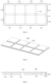
FIG. 1 is a schematic diagram of a backlight module provided by an embodiment of the present invention. -
FIG. 2 is a schematic diagram of a framework provided by the embodiment of the present invention. -
FIG. 3 is a cross-sectional view along a horizontal direction of a framework provided by an embodiment of the present invention. -
FIG. 4 is a schematic diagram of a light plate provided by an embodiment of the present invention. -
FIG. 5 is a cross-sectional view along a vertical direction of a backlight module provided by an embodiment of the present invention. -
FIG. 6 is a cross-sectional view along a horizontal direction of a backlight module provided by an embodiment of the present invention. -
FIG. 7 is a schematic diagram of a display device provided by an embodiment of the present invention. - It should be understood that the terms used herein, the specific structures and function details disclosed herein are intended for the mere purposes of describing specific embodiments and are representative. However, this application may be implemented in many alternative forms and should not be construed as being limited to the embodiments set forth herein.
- As used herein, terms "first", "second", or the like are merely used for illustrative purposes, and shall not be construed as indicating relative importance or implicitly indicating the number of technical features specified. In addition, terms "center", "transverse", "up", "down", "left", "right", "vertical", "horizontal", "top", "bottom", "inside", "outside", or the like are used to indicate orientational or relative positional relationships based on those illustrated in the drawings. They are merely intended for simplifying the description of the present disclosure, rather than indicating or implying that the device or element referred to must have a particular orientation or be constructed and operate in a particular orientation. Therefore, these terms are not to be construed as restricting the present disclosure.
- Hereinafter this application will be described in further detail with reference to the accompanying drawings and some optional embodiments.
- As shown in
FIGS. 1, 2 and4 , embodiments of the present invention disclose abacklight module 20 adopting a direct type backlight design. Thebacklight module 20 includes aframework 100, alight plate 200,lamp beads 300, and other structures. Theframework 100 includes a lightplate mounting groove 110 for fixing thelight plate 200. At least two sides of theframework 100 corresponding to the lightplate mounting groove 110 defineheat dissipation ports 120. That is, at least two sides of theframework 100 defineheat dissipation ports 120, where the at least two sides may be two sides, three sides or four sides. Furthermore, eachheat dissipation port 120 penetrates the respective sidewall of theframework 100. - The interior of the
light plate 200 is hollowed out to form acavity 210, and thecavity 210 is in communication with at least twoheat dissipation ports 120 in theframework 100. Thelamp beads 300 are disposed on thelight plate 200, and thepins 310 of thelamp beads 300 extend into thecavity 210. Theframework 100 and thelight plate 200 jointly form a supporting structure of thebacklight module 20. - Compared with the current design of the
backlight module 20 in which thelight plate 200 is built on the back plate and the back plate is used to dissipate heat from thelight plate 200, in this application the back plate structure is omitted in thebacklight module 20, and an additional structure namely theframework 100 for fixing thelight plate 200 is added, so that thelight plate 200 in combination with theframework 100 is used as the supporting structure of thebacklight module 20, namely the back structure of thebacklight module 20. Further,heat dissipation ports 120 are defined in different sides of theframework 100, and hollow structures are defined in thelight plate 200 to formcavities 210 that communicate with theseheat dissipation ports 120 to form an air flow channel connected to the outside world, so that the external airflow can enter from oneheat dissipation port 120, and come out from anotherheat dissipation port 120 through thecavity 210, so as to achieve the effect of air circulation. In this way, the heat dissipation port air outside can directly take away the heat on thelight plate 200 and the heat extending to thepins 310 in thecavity 210, effectively dissipating heat from thepins 310 of thelamp beads 300, thereby achieving the purpose of reducing the power consumption of thebacklight module 20 and improving the service life of thebacklight module 20. - In the embodiments of the present invention, the number of
light plates 200 in thebacklight module 20 may be only one. In this case, there is only one lightplate mounting groove 110 in theframework 100, and thecavity 210 in thelight plate 200 directly communicates with all theheat dissipation ports 120 in theframework 100 to form an airflow channel. The number oflight plates 200 in thebacklight module 20 can also be multiple, where the multiple here refers to two or more. Correspondingly, theframework 100 also has a plurality of lightplate mounting grooves 110 and thelight plates 200 are installed in the lightplate mounting grooves 110 in one-to-one correspondence. In this case, thecavities 210 in all thelight plates 200 communicate with each other, and form an air flow channel with theheat dissipation ports 120 in theframework 100. In this embodiment, thebacklight module 20 has eightlight plates 200 as an example for illustration, but it does not mean that thebacklight module 20 with eightlight plates 200 is preferably used in this embodiment. - Each
light plate 200 includes a plurality oflamp beads 300, where theselamp beads 300 may be ordinaryLED lamp beads 300 or MiniLED lamp beads 300, which are not to be limited here. - As shown in
FIG. 2 , in theframework 100, the lightplate mounting groove 110 is a through groove, which runs through theframework 100. In this case, theframework 100 is a grid structure. Specifically, theframework 100 includes aframe portion 130 and askeleton portion 140. Theskeleton portion 140 is composed of a plurality of crisscross branches 141. Theframe portion 130 is a square ring structure, which is disposed around theskeleton portion 140. At least two sides of theframe portion 130 define theheat dissipation ports 120 at positions corresponding to the lightplate mounting grooves 110. Each of the branches 141 defines anair channel 142, and theair channel 142 penetrates the two sides of the branch 141 corresponding to the mountinggrooves 110 of the light plate. Theheat dissipation port 120, theair channel 142 and thecavity 210 collectively form a heat dissipation channel. - Of course, the light
plate mounting groove 110 may also be a blind groove, that is, the lightplate mounting groove 110 does not penetrate theframework 100, and this design does not affect the air flow in the heat dissipation channel. But relatively speaking, after the lightplate mounting groove 110 is made as a through groove or slot more precisely, the bottom of thelight plate 200 is exposed directly from theframework 100, so that thelight plate 200 as the bottom of thebacklight module 20 is directly exposed to the outside world, making it easier to dissipate heat. - Further, the interior of the
framework 100 is hollowed. That is, in theframework 100, both theskeleton portion 140 and theframe portion 130 are hollow structures. In this case, the insides of all the branches 141 in theframework 100 are connected, and thecavities 210 in thelight plates 200 are also connected. That means the inner spaces of thewhole framework 100 and all thelight plates 200 are connected. In this way, the external airflow can flow through the insides of theframework 100 and all thelight plates 200 to take away the heat from each area, so that thebacklight module 20 can dissipate heat evenly. - Furthermore, as shown in
FIG. 3 , when theframe portion 130 is a hollow structure, correspondingly, theheat dissipation ports 120 are defined in the four outer sides of theframe portion 130, and theheat dissipation ports 120 on each side are disposed corresponding to thelight plates 200. Eachheat dissipation port 120 is disposed on a respective side of theframe portion 130 away from theframe portion 140. In addition, theheat dissipation ports 120 are each a porous structure and are arranged in an array to prevent external dust and foreign matter from entering the interior of thebacklight module 20. The side of theframe portion 130 facing theframe portion 140 is hollowed out to form ahollow portion 131, and thehollow portion 131 corresponds to a side of therespective cavity 210. After hollowing out the inside of theframe portion 130, the depth of theheat dissipation port 120 is smaller, and the outside air can fill and replace the air in the cavity of thelight plate 200 more quickly to achieve better heat dissipation. - Optionally, the porous
heat dissipation port 120 may be made into a conical structure, so that the cross-sectional area of the side of theheat dissipation port 120 facing the respectivelight plate 200 is larger than the cross-sectional area of the side of theheat dissipation port 120 facing the outside, that is, the cross-sectional area of the side facing away from the respectivelight plate 200. In this way, more air flows in from the outside, but less air enters the interior of thebacklight module 20, which will form a negative pressure, so as to accelerate the entry of outside air into thebacklight module 20, increase the air flow speed inside thebacklight module 20, and improve heat dissipation efficiency. - The
framework 100 is an integrally formed structure. That is, theframe portion 130 and theskeleton portion 140 are manufactured together or more specifically integrally, which can ensure that theframework 100 still has high strength and stability even though it is hollow inside. Furthermore, theframework 100 may be made of an aluminum alloy material. In this way, while reducing the cost of theframework 100 and reducing the weight of theframework 100, theframework 100 itself can also have better heat absorption and heat dissipation effects, and can accelerate the release of heat on thelight plate 200, thereby further improving the overall heat dissipation effect of thebacklight module 20. Of course, theframework 100 can also be made of other metals or other materials. - In the
light plate 200, the design of thecavities 210 corresponds to the design of theheat dissipation ports 120 in theframework 100. When theheat dissipation ports 120 are only defined on two opposite sides of theframework 100, thecavities 210 are each a passage that runs through thelight plate 200 in an orientation from front side to back side. When theheat dissipation ports 120 are defined on four sides of theframework 100, thecavities 210 are each a hollow structure with four open sides. - In this case, as shown in
FIG. 4, FIG. 5 andFIG. 6 , thelight plate 200 includes atop plate 220, asupport member 230 and abottom plate 240. Thesupport member 230 is located between thetop plate 220 and thebottom plate 240 and is connected with thetop plate 220 and thebottom plate 240 so that acavity 210 is formed between thetop plate 220 and thebottom plate 240. Thepins 310 of thelamp bead 300 extend through thetop plate 220 into thecavity 210. Furthermore, thelight plate 200 adopts an integrated one piece design. That is, thetop plate 220, thesupport member 230 and thebottom plate 240 are integrally formed, which not only facilitates the processing of thelight plate 200, but also improves the stability of thelight plate 200. - The
support member 230 includes fourcorner support columns 231 and acentral support column 232. The fourcorner support columns 231 respectively correspond to the four corners of thelight plate 200 and respectively connect the four corners of thetop plate 220 with the four corners of thebottom plate 240. Thecentral support column 232 is located at the center of thelight plate 200 and connects the center of thetop plate 220 with the center of thebottom plate 240. Thebottom plate 240 and thetop plate 220 of eachlight plate 200 are supported and fixed at five points, so that thetop plate 220 and thebottom plate 240 are prevented from being bent under force while ensuring the inner space of thelight plate 200. - The horizontal section of each
corner support column 231 may be a square. When thelight plate 200 is inserted into the lightplate mounting groove 110, the fourcorner support columns 231 of thelight plate 200 just abut against the four corners of the lightplate mounting groove 110 to position thelight plate 200 and facilitate the installation of thelight plate 200. The cross-section of thecentral support column 232 may be rectangular or circular, or other shapes. - After the
light plate 200 is installed in the lightplate mounting groove 110, the bottom of thelight plate 200 is flush with the bottom of theframework 100. Since thelight plate 200 and theframework 100 serve as the back of thebacklight module 20, the flat structure is beneficial to the aesthetics of thebacklight module 20. After the bottom of thelight plate 200 is flush with the bottom of theframework 100, the gap between thebottom plate 240 and theframework 100 may be further filled with sealant, so as to improve the waterproof effect on the back of thebacklight module 20 and the stability between thelight plate 200 and theframework 100. - As shown in
FIG. 6 , after thelight plate 200 is installed in the lightplate mounting groove 110, theframework 100 and thelight plate 200 form a plurality of heat dissipation channels, where the direction of the arrow in the FIG. indicates the direction of the air flow. After the air is heated and expanded, it drives the flow of air inside and outside thelight plate 200. - The width of the
cavity 210 is also the distance between two adjacentcorner support columns 231 in thelight plate 200. In this case, the width of theair channel 142 is not smaller than the width of thecavity 210, and the width of thehollow portion 131 in theframe portion 130 is not smaller than the width of thecavity 210, so that theframework 100 itself does not block the flow of air. Optionally, the cross-sectional shapes of theair channel 142, thecavity 210, and thehollow portion 131 are the same, and the three form a stable airflow channel, so that the air flows smoothly, which is beneficial to realize stable heat dissipation. - In the embodiments of the present invention, the
light plate 200 may be individually fixed to in the lightplate mounting groove 110 in theframework 100; specifically, it may be fixed in a one-to-one correspondence by means of bonding, clamping or inserting. It is also possible to adopt a unified fixing method, namely first fix single or multiplelight plates 200 together, and finally install it into the lightplate mounting groove 110 in theframework 100. Specifically, thebacklight module 20 further includes acover plate 250. Thetop plates 220 of the plurality oflight plates 200 are fixed onto thecover plate 250 in an array. Thelamp beads 300 are fixed onto thecover plate 250, and thepins 310 of thelamp beads 300 extend through thecover plate 250 and thetop plate 220 into thecavity 210. The bottoms of the edges of thecover plate 250 abut against the top of theframe portion 130 and are fixed on theframe portion 130 by means of adhesive. Alternatively, when there is only onelight plate 200 in thebacklight module 20, thislight plate 200 can also be fixed onto thecover plate 250 first, and then thelight plate 200 may be installed in theframework 100 by bonding the bottoms of the edges of thecover plate 250 to the top of theframe portion 130. - After the above-mentioned fixing method is adopted, the complicated process of one-to-one alignment and installation of the
light plates 200 is avoided, and thecover plate 250 is directly fixed onto theframework 100 to complete the installation and fixing of all thelight plates 200, which is simple and convenient. Furthermore, the design of thecover plate 250 also avoids the risk that thelight plate 200 falls off from theframework 100. In addition, thecover plate 250 covers both the lightplate mounting groove 110 and thelight plate 200, preventing hot air from flowing out towards the direction of thelamp beads 300 through the gap between thelight plate 200 and theframework 100 causing the risk of temperature rise of thelamp beads 300. - At this time, the
light plate 200 and thecover plate 250 may be integrally formed. During assembly, it is only needed to install thelamp beads 300 on thecover plate 250 one by one. Of course, thelight plate 200 can also be a separate structure from thecover plate 250. When assembling, it is only needed to paste thelight plate 200 onto thecover plate 250, so that the number oflight plates 200 may be selected depending on the actual situation, so as to meet more usage conditions. - As shown in
FIG. 7 , the present invention further discloses a display device. Thedisplay device 10 includes adisplay panel 50 and the above-mentionedbacklight module 20. Thedisplay panel 50 may be a TN (Twisted Nematic) display panel, an IPS (In-Plane Switching) display panel, a VA (Vertical Alignment) display panel, or an MVA (Multi-Domain Vertical Alignment) display panel, which is not limited here. Thebacklight module 20 not only includes the above-mentionedlight plate 200,framework 100,lamp beads 300 andcover plate 250, but also includes asealant 30 and anoptical assembly 40. Thesealant 30 is fixed to theframe portion 130 of theframework 100 and arranged around thecover plate 250, and the top of thesealant 30 is higher than the top of thelamp beads 300. The edge of theoptical assembly 40 is then fixed onto thesealant 30. Finally, thedisplay panel 50 may be directly bonded to theoptical assembly 40, or may be fixed onto thesealant 30. - The foregoing description is merely a further detailed description of the present invention made with reference to some specific illustrative embodiments, and the specific implementations of the present invention will not be construed to be limited to these illustrative embodiments. For those having ordinary skill in the technical field to which this application pertains, numerous simple deductions or substitutions may be made without departing from the concept of this application, which shall all be regarded as falling in the scope of protection of this application.
Claims (18)
- A backlight module, comprising:a framework, comprising at least one light plate mounting groove, wherein at least two sides of the framework corresponding to the at least one light plate mounting groove each define a heat dissipation port, the heat dissipation port running through a respective side wall of the framework;at least one light plate, disposed in one-to-one correspondence with and fixed in the at least one light plate mounting groove; wherein an interior of each of the at least one light plate is hollowed out to define a cavity, the cavity being connected with the respective heat dissipation port in the framework; anda plurality of lamp beads, disposed on the at least one light plate, and wherein pins of the plurality of lamp beads extend into the cavity;wherein the framework and the at least one light plate jointly form a supporting structure of the backlight module.
- The backlight module of claim 1, wherein the at least one light plate mounting groove comprises a plurality of light plate mounting grooves defined in the framework, and wherein the plurality of light plate mounting grooves are each a through groove running through the framework.
- The backlight module of claim 1, wherein the at least one light plate mounting groove comprises a plurality of light plate mounting grooves defined in the framework, and wherein the plurality of light plate mounting grooves are each a blind groove that doesn't run through the framework.
- The backlight module of claim 2, wherein the framework comprises a frame portion and a skeleton portion, wherein the skeleton portion comprises a plurality of crisscross branches, and the frame portion is disposed around the skeleton portion; wherein at least two sides of the frame portion define the heat dissipation ports at positions corresponding to the light plate mounting grooves; wherein each of the plurality of branches defines an air channel, which runs through two sides of the respective branch corresponding to the respective light plate mounting grooves; and wherein the respective heat dissipation port, air channel, and cavity collectively define a heat dissipation passage.
- The backlight module of claim 4, wherein four sides of the frame portion each define a heat dissipation port, which is disposed on a side of the frame portion away from the skeleton portion; and wherein the heat dissipation ports are each a porous structure and are arranged in an array;
wherein a side of the frame portion facing towards the skeleton portion is hollowed out to define a hollow portion, the hollow portion corresponding to one side of the cavity. - The backlight module of claim 5, wherein a cross-sectional shape of the air channel, a cross-sectional shape of the cavity, and a cross-sectional shape of the hollow portion are identical with each other.
- The backlight module of claim 5, wherein a cross-sectional area of a side of each heat dissipation port facing towards the respective light plate is greater than a cross-sectional area of a side of the heat dissipation port facing away from the light plate.
- The backlight module of claim 4, wherein each light plate comprises a top plate, a support member, and a bottom plate; the support member is disposed between the top plate and the bottom plate, and is connected with the top plate and the bottom plate, so that the cavity is defined between the top plate and the bottom plate; wherein the pins of the plurality of lamp beads extend through the top plate and into the cavity.
- The backlight module of claim 8, wherein a bottom of the bottom plate is flush with a bottom of the framework, and wherein a gap between the bottom plate and the framework is filled with a sealant.
- The backlight module of claim 8, wherein the top plate, the support member, and the bottom plate are integrally formed as one piece.
- The backlight module of claim 8, wherein the support member comprises four corner support columns and a central support column; wherein the four corner support columns respectively correspond to four corners of the respective light plate, and connect the four corners of the top plate to the four corners of the bottom plate, respectively; wherein the central support column is disposed at a center of the respective light plate, connecting a center of the top plate to a center of the bottom plate;
wherein in each light plate a width of the cavity is equal to a distance between two adjacent corner support columns, and wherein a width of the respective air channel is not less than the width of the cavity. - The backlight module as claimed in claim 11, wherein a horizontal cross section of each corner support column is a square.
- The backlight module of claim 8, wherein the backlight module further comprises a cover plate; the top plates of the plurality of light plates are fixed onto the cover plate in an array; the plurality of lamp beads are fixed onto the cover plate, and the pins of the plurality of lamp beads extend through the cover plate and the top plate into cavity;
wherein bottoms of edges of the cover plate abut against a top of the frame portion, and is bonded and fixed onto the frame portion. - The backlight module of claim 13, wherein the at least one light plate and the cover plate are integrally formed, and wherein the framework is an integrally formed structure.
- The backlight module of claim 14, wherein the framework is made of aluminum alloy.
- The backlight module of claim 4, wherein the plurality of branches are each a hollow structure, and wherein insides of the plurality of branches in the skeleton portion are connected.
- A backlight module, comprising:a framework, comprising a plurality of light plate mounting grooves, each being a through groove running through the framework; the framework comprises a frame portion and a skeleton portion; the frame portion comprises a plurality of crisscross branches, and is disposed around the skeleton portion; wherein four sides of the frame portion each define at least one heat dissipation port corresponding to positions of the plurality of light plate mounting grooves; each of the plurality of branches defines at least one air channel running through two sides of the respective branch corresponding to the respective light plate mounting grooves; and wherein the respective heat dissipation port, air channel, and cavity collectively define a heat dissipation channel;a plurality of light plates, disposed in one-to-one correspondence with and fixed in the plurality of light plate mounting grooves; wherein each of the plurality of light plates comprises a top plate, a support member, and a bottom plate; wherein the support member is disposed between the top plate and the bottom plate, and connected with the top plate and the bottom plate, so that the respective cavity is defined between the top plate and the bottom plate; anda plurality of lamp beads, disposed on the top plate, and wherein pins of the plurality of lamp beads extend through the top plate into the cavity;wherein the framework and the at least one light plate jointly form a supporting structure of the backlight module.
- A display device, comprising a display panel and a backlight module configured to provide backlight for the display panel, the backlight module comprising:a framework, comprising at least one light plate mounting groove, wherein at least two sides of the framework corresponding to the at least one light plate mounting groove each define a heat dissipation port, the heat dissipation port running through a respective side wall of the framework;at least one light plate, disposed in one-to-one correspondence with and fixed in the at least one light plate mounting groove; wherein an interior of each of the at least one light plate is hollowed out to define a cavity, the cavity being in communication with the respective heat dissipation port in the framework; anda plurality of lamp beads, disposed on the at least one light plate, and wherein pins of the plurality of lamp beads extend into the cavity;wherein the framework and the at least one light plate jointly form a supporting structure of the backlight module.
Applications Claiming Priority (2)
| Application Number | Priority Date | Filing Date | Title |
|---|---|---|---|
| CN202211011543.4A CN115113439B (en) | 2022-08-23 | 2022-08-23 | Backlight module and display device |
| PCT/CN2022/135752 WO2024040780A1 (en) | 2022-08-23 | 2022-12-01 | Backlight module and display device |
Publications (2)
| Publication Number | Publication Date |
|---|---|
| EP4567506A1 true EP4567506A1 (en) | 2025-06-11 |
| EP4567506A4 EP4567506A4 (en) | 2025-11-19 |
Family
ID=83336234
Family Applications (1)
| Application Number | Title | Priority Date | Filing Date |
|---|---|---|---|
| EP22956315.0A Pending EP4567506A4 (en) | 2022-08-23 | 2022-12-01 | REAR LIGHTING MODULE AND DISPLAY DEVICE |
Country Status (6)
| Country | Link |
|---|---|
| US (1) | US11789317B1 (en) |
| EP (1) | EP4567506A4 (en) |
| JP (1) | JP7837440B2 (en) |
| KR (1) | KR20250041058A (en) |
| CN (1) | CN115113439B (en) |
| WO (1) | WO2024040780A1 (en) |
Families Citing this family (5)
| Publication number | Priority date | Publication date | Assignee | Title |
|---|---|---|---|---|
| CN115113439B (en) * | 2022-08-23 | 2022-12-23 | 惠科股份有限公司 | Backlight module and display device |
| CN115840312B (en) * | 2022-12-26 | 2024-09-24 | 合肥鑫晟光电科技有限公司 | Back panel, backlight module and display device |
| CN116072015B (en) * | 2023-03-03 | 2023-06-13 | 惠科股份有限公司 | Support and display device |
| CN116645875B (en) * | 2023-06-15 | 2025-07-29 | 深圳帝显高端制造方案解决有限公司 | Mini LED backlight module |
| CN117970692B (en) * | 2024-03-25 | 2024-08-20 | 深圳帝显高端制造方案解决有限公司 | LCM display module and LCM display screen thereof |
Family Cites Families (56)
| Publication number | Priority date | Publication date | Assignee | Title |
|---|---|---|---|---|
| JP4083659B2 (en) * | 2002-10-10 | 2008-04-30 | バルコ・ナムローゼ・フエンノートシャップ | Panel display and tiled display |
| TWI263836B (en) * | 2004-11-12 | 2006-10-11 | Coretronic Corp | Heat dissipation method of display backlight unit and the structure thereof |
| TWI345661B (en) * | 2006-10-30 | 2011-07-21 | Coretronic Corp | Backlight module |
| CN201242617Y (en) * | 2008-06-27 | 2009-05-20 | 上海生泉生物科技有限公司 | X-ray film reading machine |
| TWM350731U (en) * | 2008-07-24 | 2009-02-11 | Top Victory Invest Ltd | Backlight module and liquid crystal display |
| JP2010102227A (en) * | 2008-10-27 | 2010-05-06 | Kita Denshi Corp | Outdoor both side display device |
| CN201322255Y (en) * | 2008-11-14 | 2009-10-07 | 中华映管股份有限公司 | Liquid crystal display device and backlight module |
| US10827656B2 (en) * | 2008-12-18 | 2020-11-03 | Manufacturing Resources International, Inc. | System for cooling an electronic image assembly with circulating gas and ambient gas |
| KR20110104833A (en) * | 2010-03-17 | 2011-09-23 | 엘지전자 주식회사 | Backlight unit and display device including same |
| KR101709782B1 (en) * | 2010-11-08 | 2017-02-27 | 서울반도체 주식회사 | LED backlight unit |
| CN102102863B (en) * | 2010-11-16 | 2013-04-24 | 深圳市华星光电技术有限公司 | Luminous source radiating structure and backlight module |
| WO2012157548A1 (en) * | 2011-05-18 | 2012-11-22 | シャープ株式会社 | Illumination device and display device |
| CN103032704B (en) * | 2011-09-30 | 2016-02-03 | 深圳市邦贝尔电子有限公司 | Led |
| CN102345836B (en) * | 2011-11-18 | 2015-02-11 | 深圳市华星光电技术有限公司 | Back plate, backlight module and liquid crystal display device |
| CN102566105A (en) * | 2012-03-15 | 2012-07-11 | 深圳市华星光电技术有限公司 | Liquid crystal display device |
| CN102628566B (en) * | 2012-03-27 | 2015-02-18 | 深圳市华星光电技术有限公司 | Backlight module, liquid crystal display device and light source of backlight module |
| CN102661533A (en) * | 2012-04-11 | 2012-09-12 | 深圳市华星光电技术有限公司 | Backlight module and LCD (liquid crystal display) device |
| CN102818193B (en) * | 2012-08-20 | 2014-12-10 | 创维液晶器件(深圳)有限公司 | Direct type LED (light emitting diode) backlight module and display device of direct type LED backlight module |
| CN102865503B (en) * | 2012-08-28 | 2015-09-30 | 深圳市华星光电技术有限公司 | Backlight module and heat abstractor |
| CN203082706U (en) * | 2013-02-05 | 2013-07-24 | 冠捷显示科技(厦门)有限公司 | Novel direct-light-type light-emitting diode (LED) backlight module |
| KR102081928B1 (en) * | 2013-04-24 | 2020-02-26 | 엘지전자 주식회사 | Digital signage |
| KR102136203B1 (en) * | 2014-02-03 | 2020-08-14 | 삼성디스플레이 주식회사 | Backlight unit and liquid crystal display comprising the same |
| CN204153596U (en) * | 2014-10-14 | 2015-02-11 | 杭州海创电子有限公司 | A kind of backlight for LED LCDs |
| CN204300865U (en) * | 2015-01-08 | 2015-04-29 | 京东方科技集团股份有限公司 | A kind of liquid crystal indicator and backlight module thereof |
| WO2016183772A1 (en) * | 2015-05-18 | 2016-11-24 | 上海启钧电子有限公司 | Integrated double-sided display module structure |
| CN205071602U (en) * | 2015-11-13 | 2016-03-02 | 乐视致新电子科技(天津)有限公司 | Heat radiation structure and terminal |
| CN205643963U (en) * | 2016-04-28 | 2016-10-12 | 乐视控股(北京)有限公司 | Backlight unit , display module assembly and display device |
| CN106154646B (en) * | 2016-09-23 | 2020-06-30 | 京东方科技集团股份有限公司 | A lamp panel, a backlight module and a liquid crystal display device |
| JP2018049233A (en) * | 2016-09-23 | 2018-03-29 | パナソニック液晶ディスプレイ株式会社 | Liquid crystal display device |
| KR102258444B1 (en) * | 2017-03-13 | 2021-05-31 | 엘지전자 주식회사 | Display device |
| CN206906626U (en) * | 2017-03-21 | 2018-01-19 | 福建海佳彩亮光电科技有限公司 | A kind of LED backlight module |
| CN206906826U (en) | 2017-03-28 | 2018-01-19 | 苏州工业园区职业技术学院 | A kind of intelligent automobile debugging system using camera |
| EP3602528B1 (en) | 2017-03-29 | 2023-09-27 | Noble International, Inc. | Prefilled syringe plunger simulation training device |
| WO2018199452A1 (en) * | 2017-04-23 | 2018-11-01 | Lg Electronics Inc. | Display device |
| TWI693448B (en) * | 2018-07-04 | 2020-05-11 | 光遠科技股份有限公司 | Heat exchange device and display device |
| CN209879206U (en) * | 2019-05-28 | 2019-12-31 | 合肥惠科金扬科技有限公司 | Backlight module assembly structure and display device |
| CN110515240B (en) * | 2019-08-30 | 2022-10-18 | 厦门天马微电子有限公司 | Backlight module, manufacturing method thereof and display device |
| WO2021218478A1 (en) * | 2020-04-28 | 2021-11-04 | 海信视像科技股份有限公司 | Display apparatus |
| TWI766274B (en) * | 2020-05-11 | 2022-06-01 | 瑞軒科技股份有限公司 | Brightness enhancement support pin and backlight module with the same |
| CN212658916U (en) * | 2020-06-03 | 2021-03-05 | 北京易美新创科技有限公司 | Direct type backlight module |
| CN113820885B (en) * | 2020-06-18 | 2022-11-04 | 京东方科技集团股份有限公司 | A curved backlight module and display device |
| CN212749470U (en) * | 2020-06-30 | 2021-03-19 | 昆山龙腾光电股份有限公司 | Backlight module and display device |
| CN112285974B (en) * | 2020-10-30 | 2021-12-03 | 惠州市华星光电技术有限公司 | Backlight module and display device |
| CN213399140U (en) * | 2020-11-23 | 2021-06-08 | 四川长虹电器股份有限公司 | Direct type backlight module supporting structure |
| CN113109970A (en) * | 2021-04-08 | 2021-07-13 | 惠科股份有限公司 | Backlight module and display |
| CN113219719B (en) * | 2021-04-23 | 2023-06-30 | 成都京东方显示科技有限公司 | Backlight module, liquid crystal module and display device |
| CN113467127B (en) * | 2021-05-31 | 2022-08-05 | 惠科股份有限公司 | Backlight module and display device |
| CN114187832A (en) * | 2021-12-01 | 2022-03-15 | 惠州华星光电显示有限公司 | Backlight module and display device |
| CN114285243A (en) | 2021-12-10 | 2022-04-05 | 山东大学 | A magnetic hydro-cavitation nano-dispersion device |
| CN216526643U (en) * | 2021-12-28 | 2022-05-13 | 厦门弘汉光电科技有限公司 | Lamp panel for enhancing miniLED backlight source partition dimming effect |
| CN114265239A (en) * | 2021-12-28 | 2022-04-01 | 绵阳惠科光电科技有限公司 | Backlight module and display device |
| CN216697684U (en) * | 2021-12-29 | 2022-06-07 | 惠科股份有限公司 | Backlight module and display device |
| CN114265243B (en) * | 2022-03-02 | 2022-07-12 | 惠科股份有限公司 | Backlight module and display device |
| CN114677917B (en) * | 2022-03-11 | 2024-03-19 | 绵阳惠科光电科技有限公司 | Backlight modules and display devices |
| CN114660851B (en) * | 2022-04-12 | 2024-02-09 | Tcl华星光电技术有限公司 | Backlight module and display device |
| CN115113439B (en) * | 2022-08-23 | 2022-12-23 | 惠科股份有限公司 | Backlight module and display device |
-
2022
- 2022-08-23 CN CN202211011543.4A patent/CN115113439B/en active Active
- 2022-12-01 WO PCT/CN2022/135752 patent/WO2024040780A1/en not_active Ceased
- 2022-12-01 KR KR1020257006564A patent/KR20250041058A/en active Pending
- 2022-12-01 JP JP2024574827A patent/JP7837440B2/en active Active
- 2022-12-01 EP EP22956315.0A patent/EP4567506A4/en active Pending
- 2022-12-27 US US18/088,785 patent/US11789317B1/en active Active
Also Published As
| Publication number | Publication date |
|---|---|
| JP7837440B2 (en) | 2026-03-30 |
| CN115113439B (en) | 2022-12-23 |
| KR20250041058A (en) | 2025-03-25 |
| CN115113439A (en) | 2022-09-27 |
| JP2025519839A (en) | 2025-06-26 |
| US11789317B1 (en) | 2023-10-17 |
| EP4567506A4 (en) | 2025-11-19 |
| WO2024040780A1 (en) | 2024-02-29 |
Similar Documents
| Publication | Publication Date | Title |
|---|---|---|
| US11789317B1 (en) | Backlight module and display device | |
| CN102352986A (en) | Backlight module and liquid crystal television | |
| CN102163392A (en) | Light emitting diode (LED) assembled screen | |
| CN113485049A (en) | Display device | |
| EP3904952B1 (en) | Direct-type backlight module and display | |
| CN218721109U (en) | LED module | |
| CN113109969A (en) | Backlight device and display | |
| CN202142244U (en) | Display screen mounting frame | |
| US12253757B2 (en) | Backlight module and display device including the same | |
| CN201838264U (en) | Combined LED striped screen | |
| CN117082820A (en) | LED display panel and LED display screen | |
| CN216084178U (en) | Novel outdoor grille screen transparent screen box | |
| CN217064180U (en) | Automatically controlled box structure convenient to heat dissipation | |
| CN214174770U (en) | Symmetrical double-sided screen liquid crystal module structure | |
| CN221101620U (en) | A small pitch ultra-thin display screen | |
| CN103162194B (en) | Backlight module | |
| CN214705295U (en) | Outdoor display equipment with high-efficient heat dissipation and thin energy-conserving non-maintaining structure has | |
| CN223155626U (en) | LED display module for preventing side light leakage | |
| CN112485944A (en) | Novel Mini-LED quantum dot structure backlight module for liquid crystal display television | |
| US20130128530A1 (en) | Backlight System | |
| CN110208974B (en) | Combined type backlight box structure of vehicle-mounted display screen | |
| CN213240730U (en) | Do benefit to radiating concatenation screen | |
| CN218512756U (en) | Novel medium and small size backlight source structure | |
| CN206209247U (en) | A kind of high intensity display backlight plate | |
| CN204166833U (en) | The sub-display screen of a kind of LED electrical |
Legal Events
| Date | Code | Title | Description |
|---|---|---|---|
| STAA | Information on the status of an ep patent application or granted ep patent |
Free format text: STATUS: THE INTERNATIONAL PUBLICATION HAS BEEN MADE |
|
| PUAI | Public reference made under article 153(3) epc to a published international application that has entered the european phase |
Free format text: ORIGINAL CODE: 0009012 |
|
| STAA | Information on the status of an ep patent application or granted ep patent |
Free format text: STATUS: REQUEST FOR EXAMINATION WAS MADE |
|
| 17P | Request for examination filed |
Effective date: 20250305 |
|
| AK | Designated contracting states |
Kind code of ref document: A1 Designated state(s): AL AT BE BG CH CY CZ DE DK EE ES FI FR GB GR HR HU IE IS IT LI LT LU LV MC ME MK MT NL NO PL PT RO RS SE SI SK SM TR |
|
| A4 | Supplementary search report drawn up and despatched |
Effective date: 20251016 |
|
| RIC1 | Information provided on ipc code assigned before grant |
Ipc: G02F 1/13357 20060101AFI20251010BHEP |
|
| DAV | Request for validation of the european patent (deleted) | ||
| DAX | Request for extension of the european patent (deleted) |