EP4567395A1 - Sealed microelectromechanical membrane device - Google Patents
Sealed microelectromechanical membrane device Download PDFInfo
- Publication number
- EP4567395A1 EP4567395A1 EP24216761.7A EP24216761A EP4567395A1 EP 4567395 A1 EP4567395 A1 EP 4567395A1 EP 24216761 A EP24216761 A EP 24216761A EP 4567395 A1 EP4567395 A1 EP 4567395A1
- Authority
- EP
- European Patent Office
- Prior art keywords
- platform
- supporting body
- flexure
- sealing strip
- gap
- Prior art date
- Legal status (The legal status is an assumption and is not a legal conclusion. Google has not performed a legal analysis and makes no representation as to the accuracy of the status listed.)
- Pending
Links
Images



Classifications
-
- B—PERFORMING OPERATIONS; TRANSPORTING
- B81—MICROSTRUCTURAL TECHNOLOGY
- B81B—MICROSTRUCTURAL DEVICES OR SYSTEMS, e.g. MICROMECHANICAL DEVICES
- B81B3/00—Devices comprising flexible or deformable elements, e.g. comprising elastic tongues or membranes
- B81B3/0064—Constitution or structural means for improving or controlling the physical properties of a device
- B81B3/0067—Mechanical properties
- B81B3/0072—For controlling internal stress or strain in moving or flexible elements, e.g. stress compensating layers
-
- G—PHYSICS
- G01—MEASURING; TESTING
- G01L—MEASURING FORCE, STRESS, TORQUE, WORK, MECHANICAL POWER, MECHANICAL EFFICIENCY, OR FLUID PRESSURE
- G01L9/00—Measuring steady of quasi-steady pressure of fluid or fluent solid material by electric or magnetic pressure-sensitive elements; Transmitting or indicating the displacement of mechanical pressure-sensitive elements, used to measure the steady or quasi-steady pressure of a fluid or fluent solid material, by electric or magnetic means
- G01L9/0041—Transmitting or indicating the displacement of flexible diaphragms
- G01L9/0051—Transmitting or indicating the displacement of flexible diaphragms using variations in ohmic resistance
- G01L9/0052—Transmitting or indicating the displacement of flexible diaphragms using variations in ohmic resistance of piezoresistive elements
-
- B—PERFORMING OPERATIONS; TRANSPORTING
- B81—MICROSTRUCTURAL TECHNOLOGY
- B81B—MICROSTRUCTURAL DEVICES OR SYSTEMS, e.g. MICROMECHANICAL DEVICES
- B81B7/00—Microstructural systems ; Auxiliary parts of microstructural devices or systems
- B81B7/0032—Packages or encapsulation
- B81B7/0045—Packages or encapsulation for reducing stress inside of the package structure
-
- B—PERFORMING OPERATIONS; TRANSPORTING
- B81—MICROSTRUCTURAL TECHNOLOGY
- B81B—MICROSTRUCTURAL DEVICES OR SYSTEMS, e.g. MICROMECHANICAL DEVICES
- B81B7/00—Microstructural systems ; Auxiliary parts of microstructural devices or systems
- B81B7/02—Microstructural systems ; Auxiliary parts of microstructural devices or systems containing distinct electrical or optical devices of particular relevance for their function, e.g. microelectro-mechanical systems [MEMS]
-
- B—PERFORMING OPERATIONS; TRANSPORTING
- B81—MICROSTRUCTURAL TECHNOLOGY
- B81C—PROCESSES OR APPARATUS SPECIALLY ADAPTED FOR THE MANUFACTURE OR TREATMENT OF MICROSTRUCTURAL DEVICES OR SYSTEMS
- B81C1/00—Manufacture or treatment of devices or systems in or on a substrate
- B81C1/00015—Manufacture or treatment of devices or systems in or on a substrate for manufacturing microsystems
- B81C1/00261—Processes for packaging MEMS devices
- B81C1/00325—Processes for packaging MEMS devices for reducing stress inside of the package structure
-
- B—PERFORMING OPERATIONS; TRANSPORTING
- B81—MICROSTRUCTURAL TECHNOLOGY
- B81C—PROCESSES OR APPARATUS SPECIALLY ADAPTED FOR THE MANUFACTURE OR TREATMENT OF MICROSTRUCTURAL DEVICES OR SYSTEMS
- B81C1/00—Manufacture or treatment of devices or systems in or on a substrate
- B81C1/00642—Manufacture or treatment of devices or systems in or on a substrate for improving the physical properties of a device
- B81C1/0065—Mechanical properties
- B81C1/00666—Treatments for controlling internal stress or strain in MEMS structures
-
- G—PHYSICS
- G01—MEASURING; TESTING
- G01L—MEASURING FORCE, STRESS, TORQUE, WORK, MECHANICAL POWER, MECHANICAL EFFICIENCY, OR FLUID PRESSURE
- G01L19/00—Details of, or accessories for, apparatus for measuring steady or quasi-steady pressure of a fluent medium insofar as such details or accessories are not special to particular types of pressure gauges
- G01L19/14—Housings
- G01L19/145—Housings with stress relieving means
- G01L19/146—Housings with stress relieving means using flexible element between the transducer and the support
-
- G—PHYSICS
- G01—MEASURING; TESTING
- G01L—MEASURING FORCE, STRESS, TORQUE, WORK, MECHANICAL POWER, MECHANICAL EFFICIENCY, OR FLUID PRESSURE
- G01L9/00—Measuring steady of quasi-steady pressure of fluid or fluent solid material by electric or magnetic pressure-sensitive elements; Transmitting or indicating the displacement of mechanical pressure-sensitive elements, used to measure the steady or quasi-steady pressure of a fluid or fluent solid material, by electric or magnetic means
- G01L9/0041—Transmitting or indicating the displacement of flexible diaphragms
-
- G—PHYSICS
- G01—MEASURING; TESTING
- G01L—MEASURING FORCE, STRESS, TORQUE, WORK, MECHANICAL POWER, MECHANICAL EFFICIENCY, OR FLUID PRESSURE
- G01L9/00—Measuring steady of quasi-steady pressure of fluid or fluent solid material by electric or magnetic pressure-sensitive elements; Transmitting or indicating the displacement of mechanical pressure-sensitive elements, used to measure the steady or quasi-steady pressure of a fluid or fluent solid material, by electric or magnetic means
- G01L9/0041—Transmitting or indicating the displacement of flexible diaphragms
- G01L9/0042—Constructional details associated with semiconductive diaphragm sensors, e.g. etching, or constructional details of non-semiconductive diaphragms
- G01L9/0045—Diaphragm associated with a buried cavity
-
- G—PHYSICS
- G01—MEASURING; TESTING
- G01L—MEASURING FORCE, STRESS, TORQUE, WORK, MECHANICAL POWER, MECHANICAL EFFICIENCY, OR FLUID PRESSURE
- G01L9/00—Measuring steady of quasi-steady pressure of fluid or fluent solid material by electric or magnetic pressure-sensitive elements; Transmitting or indicating the displacement of mechanical pressure-sensitive elements, used to measure the steady or quasi-steady pressure of a fluid or fluent solid material, by electric or magnetic means
- G01L9/0041—Transmitting or indicating the displacement of flexible diaphragms
- G01L9/0042—Constructional details associated with semiconductive diaphragm sensors, e.g. etching, or constructional details of non-semiconductive diaphragms
- G01L9/0048—Details about the mounting of the diaphragm to its support or about the diaphragm edges, e.g. notches, round shapes for stress relief
-
- B—PERFORMING OPERATIONS; TRANSPORTING
- B81—MICROSTRUCTURAL TECHNOLOGY
- B81B—MICROSTRUCTURAL DEVICES OR SYSTEMS, e.g. MICROMECHANICAL DEVICES
- B81B2201/00—Specific applications of microelectromechanical systems
- B81B2201/02—Sensors
- B81B2201/0264—Pressure sensors
-
- B—PERFORMING OPERATIONS; TRANSPORTING
- B81—MICROSTRUCTURAL TECHNOLOGY
- B81B—MICROSTRUCTURAL DEVICES OR SYSTEMS, e.g. MICROMECHANICAL DEVICES
- B81B2203/00—Basic microelectromechanical structures
- B81B2203/01—Suspended structures, i.e. structures allowing a movement
- B81B2203/0127—Diaphragms, i.e. structures separating two media that can control the passage from one medium to another; Membranes, i.e. diaphragms with filtering function
-
- B—PERFORMING OPERATIONS; TRANSPORTING
- B81—MICROSTRUCTURAL TECHNOLOGY
- B81C—PROCESSES OR APPARATUS SPECIALLY ADAPTED FOR THE MANUFACTURE OR TREATMENT OF MICROSTRUCTURAL DEVICES OR SYSTEMS
- B81C2203/00—Forming microstructural systems
- B81C2203/01—Packaging MEMS
- B81C2203/0172—Seals
- B81C2203/019—Seals characterised by the material or arrangement of seals between parts
Definitions
- the membrane 5 is formed on the platform 3 and closes a buried cavity 11, incorporated in the platform 3, on one side.
- the buried cavity 11 is sealed by the membrane 5 and defines a pressure-controlled reference chamber.
- the membrane 5 is of semiconductor material, for example monocrystalline silicon, and may be capacitively coupled to one or more electrodes on the bottom of the buried cavity 11 or be provided with sensitive piezoresistive structures.
- the membrane 5 is exposed (directly or indirectly) to the pressure of the external environment.
- Conductive lines (not shown) run from the membrane 5 along the flexure 7 up to pads (not shown) and serve for the electrical coupling of the sensor 1 with the outside, for example an electronic system having the sensor 1 incorporated therein.
- a sealing strip 15 extends along the gap 10 on the major face 2a of the supporting body 2 and, in part, on the flexure 7 and on the platform 3.
- the sealing strip 15 sealingly adheres to the supporting body 2, to the flexure 7 and to the platform 3 along the edges of the gap 10 and seals the gap 10 and the recess 8 having the platform 10 housed therein.
- the sealing strip here indicated by 115, is of an ultraviolet curable ink or UV-curable ink, deposited on the major face 2a of the supporting body 2, along the gap 10.
- waterproofed sensors may also be manufactured using less expensive bases than ceramic bases for assembling the sensor, because the deformations of the base do not affect the output owing to the fact that the membrane is formed on the movable platform.
- techniques for bonding the sensor to a support in particular flip chip or WLCSP (Wafer Level Chip Scale Package) techniques, may also be used in a more flexible manner.
- the selection of the Young's modulus and the lowest coefficient of thermal expansion in the ranges mentioned above ensures, on the one hand, that the gap remains effectively sealed and, on the other, that the sealing strip does not stiffen the structure to the point of conveying thermomechanical stresses from the supporting body to the platform and therefore the membrane. Furthermore, the sealing strip may contribute to the action of the stoppers which limit the displacements of the platform to avoid possible damage.
- Figures 4-13 illustrate a process for manufacturing the sensor 1 of Figures 1 and 2 starting from a semiconductor wafer 20 comprising a substrate 20', for example of monocrystalline silicon.
- the substrate 20' is etched to form a grid or matrix of structures 21, for example pillars or walls, separated by trenches 22 in a region corresponding to a bottom of the recess 8, which will be defined below.
- the material forming the structures 21 is redistributed by an annealing step and a cavity 23 is formed which substantially extends throughout the amplitude of the recess 8 ( Figure 6 ).
- the buried cavity 11 and the membrane 5 are then formed.
- the thickness of the membrane 5 may be determined by controlling the thickness of the new epitaxial layer, not illustrated here in detail.
- the substrate 20', the epitaxial layer 20" and the new epitaxial layer not shown define the supporting body 2 as it will be obtained at the end of the process, after dicing the wafer 20.
- the supporting body 2 For convenience, in Figures 7 and following, and in the related description, reference will be made to the supporting body 2.
- the conductive lines for the membrane and, according to design preferences, piezoresistive regions, also not illustrated, are then formed by processing steps not illustrated.
- the first dielectric layer 12 is deposited on the wafer 20 and selectively removed on the membrane 5 and along the path where the gap 10 will subsequently be formed ( Figure 8 ) .
- the second dielectric layer 13 is conformally deposited on the wafer 20 ( Figure 9 ).
- an anisotropic etch for example a trench etch, is then performed along the path of the gap 10, up to reaching at least the cavity 23 in depth.
- the trench etch opens the gap 10 and defines the platform 3, the flexure 7 and the recess 8.
- the first dielectric layer 12 in this step also functions as a spacer and separates the sheet 25 from the membrane 5 and from the access of the gap 10.
- a photoresist layer 26 is deposited on the sheet 25 and patterned by a photolithographic process, as shown in Figure 12 , to form an etching mask 27 which covers the sheet 25 along the path of the gap 10 and has a shape corresponding to the sealing strip 15.
- the photoresist layer 26 is exposed and selectively removed using the etching mask 27 to form the sealing strip 15 along the edges of the gap 10 ( Figure 13 ).
- a strip 115' of UV-curable ink is deposited along the gap 10 ( Figure 14 ).
- the surface tension prevents the UV-curable ink from penetrating into the recess 8.
- connection of the platform to the supporting body at a single point and through a single flexure is particularly advantageous because it minimizes the strains conveyed to the platform and to the membrane in the event of deformation of the supporting body.
- multiple flexures may be included, for example on opposite sides of the platform.
- the gap may be divided into multiple sections and for each section a respective sealing strip of the type described may be provided.
- sealing strip materials forming the sealing strip are not limited to those described.
Landscapes
- Engineering & Computer Science (AREA)
- Microelectronics & Electronic Packaging (AREA)
- Physics & Mathematics (AREA)
- General Physics & Mathematics (AREA)
- Computer Hardware Design (AREA)
- Manufacturing & Machinery (AREA)
- Chemical & Material Sciences (AREA)
- Analytical Chemistry (AREA)
- Mechanical Engineering (AREA)
- Health & Medical Sciences (AREA)
- Child & Adolescent Psychology (AREA)
- Micromachines (AREA)
- Measuring Fluid Pressure (AREA)
Abstract
Description
- The present invention relates to a sealed microelectromechanical (MEMS) membrane device and a method for manufacturing a sealed microelectromechanical membrane device.
- As is known, an issue common to microelectromechanical membrane sensors, in particular to pressure sensors, relates to the effects of mounting operations. Generally, microelectromechanical membrane sensors and related control devices are manufactured into respective distinct semiconductor chips (a sensor chip and a control chip or ASIC - Application Specific Integrated Circuit - chip), which are bonded to a base and incorporated in a packaging structure. Subsequently, the base is soldered to a Printed Circuit Board or PCB for electrical and mechanical coupling to a user system.
- In the absence of suitable measures, soldering causes significant thermal stress which, due to the different coefficients of thermal expansion, may deform the sensor chip and induce mechanical stresses on the membrane, leading to a drift in the sensing with respect to the calibration values.
- To reduce the negative effects of thermal stress due to soldering, ceramic substrates are sometimes used as bases for assembling the sensor chip and the control chip. In fact, ceramic has the advantage of high stiffness and therefore deforms little with respect to polymeric substrates. On the other hand, ceramic substrates are expensive and do not allow the use of some advantageous and very common assembling techniques, such as flip chip or WLCSP (Wafer Level Chip Scale Package) techniques. The design freedom of membrane pressure sensors is thus limited.
- According to a different solution, the membrane that operates as a transducer is formed in a suspended platform obtained from the sensor chip and connected thereto by flexures. The main portion of the sensor chip functions as a supporting body for the platform. The flexures may almost completely absorb the deformations of the sensor chip, as well as any shocks and vibrations, and preserve the membrane from stresses. However, if the solution is very effective in reducing the drift caused by thermomechanical stresses, it may be difficult to obtain other advantageous characteristics in many circumstances. In fact, in microelectromechanical pressure sensors, the membrane is in fluidic communication with the outside to be able to receive the pressure signals to be transduced, but, at the same time, it is often useful for the same membrane to be protected from potentially harmful agents, such as dust and humidity. Therefore, the sensitive portion of the microelectromechanical membrane device may be embedded in a potting gel, which has the property of conveying pressure variations from the outside and acts as a barrier for impurities. In sensors with suspended platform, however, waterproofing through gel deposition may be difficult to obtain. Since the interstices between the platform, the flexures and the supporting body have micrometric dimensions, the gel viscosity may make filling problematic and cause, for example, the formation of bubbles, which may affect the propagation and transduction of the pressure signals or make waterproofing ineffective. The structure with platform elastically coupled to the supporting body is therefore poorly compatible with waterproofing.
- It is therefore an aim of the present invention to provide a microelectromechanical device and a method for manufacturing a microelectromechanical device which allow the limitations described to be overcome or at least mitigated.
- According to the present invention, there are provided a microelectromechanical device and a method for manufacturing a microelectromechanical device as defined in
claims - For a better understanding of the present invention, preferred embodiments are provided, by way of non-limiting example, with reference to the attached drawings, wherein:
-
Figure 1 is a top-plan view of a microelectromechanical membrane sensor in accordance with an embodiment of the present invention; -
Figure 2 is a cross-section through the sensor ofFigure 1 , taken along line II-II ofFigure 1 ; -
Figure 3 is a cross-section through a microelectromechanical pressure sensor in accordance with a different embodiment of the present invention; -
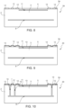
Figures 4-13 are cross-sections through a semiconductor wafer in subsequent processing steps of a process for manufacturing a microelectromechanical pressure sensor in accordance with an embodiment of the present invention; and -
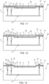
Figures 14-15 are cross-sections through a semiconductor wafer in subsequent processing steps of a process for manufacturing a microelectromechanical pressure sensor in accordance with a different embodiment of the present invention. - The following description refers to the arrangement shown in the drawings; consequently, expressions such as "above", "below", "upper", "lower", "at the top", "at the bottom", "right", "left" and the like relate to the attached Figures and are not to be interpreted in a limiting manner.
- With reference to
Figure 1 , a microelectromechanical membrane sensor, in particular a pressure sensor, is indicated as a whole with thenumber 1 and comprises a supportingbody 2 and aplatform 3, which houses amembrane 5 and is connected to the supportingbody 2 by aflexure 7. - The supporting
body 2 is a die of semiconductor material, for example monocrystalline and/or polycrystalline silicon. - The
platform 3 is housed in arecess 8 obtained in amajor face 2a of the supportingbody 2 and is kept suspended on asurface 2a of the same supportingbody 2 by theflexure 7. More in detail, theplatform 3 has generally a quadrangular, for example rectangular, shape and is spaced from thesurface 2a. - In one embodiment, the
flexure 7 is L-shaped and connects a vertex 3a of theplatform 3 to the supportingbody 2. A first branch 7a of theflexure 7 is anchored to the supportingbody 2 and extends parallel to one side of theplatform 3. A second branch 7b of theflexure 7, that is shorter, is consecutive and perpendicular to the first branch 7a and is bonded to the vertex 3a of theplatform 3. - A
spiral gap 10 laterally separates theplatform 3 and theflexure 7 from the supportingbody 2. In particular, thegap 10 runs between the supportingbody 2 and the first branch 7a of theflexure 7, then along the second branch 7b and along three sides of theplatform 3 and finally between theplatform 3 and the first branch 7a, up to the second branch 7b of theflexure 7. For example, the gap may have a width comprised between 3 µm and 30 µm, in particular 7 µm in one embodiment. - The
flexure 7 has a thickness substantially equal to the thickness of theplatform 3 and is shaped so as to allow, within the limits imposed by the dimensions of thegap 10, so-called in-plane movements of theplatform 3, that is, in the absence of deformations of the supportingbody 2, movements substantially parallel to themajor face 2a of the supporting body 2 (and of the platform 3). Out-of-plane movements, that is perpendicular to in-plane movements, are instead substantially prevented. Possibly, theflexure 7 may allow torsions around an axis of the first branch 7a, which may help accommodate deformations of the supportingbody 2, for example following thermal stresses, without conveying significant strains to theplatform 3. - The
microelectromechanical pressure sensor 1 may also be provided with stoppers (not shown for simplicity) which further limit the movement of theplatform 3. - The
membrane 5 is formed on theplatform 3 and closes a buriedcavity 11, incorporated in theplatform 3, on one side. In one embodiment, the buriedcavity 11 is sealed by themembrane 5 and defines a pressure-controlled reference chamber. Themembrane 5 is of semiconductor material, for example monocrystalline silicon, and may be capacitively coupled to one or more electrodes on the bottom of the buriedcavity 11 or be provided with sensitive piezoresistive structures. On one side opposite to the buriedcavity 11, themembrane 5 is exposed (directly or indirectly) to the pressure of the external environment. Conductive lines (not shown) run from themembrane 5 along theflexure 7 up to pads (not shown) and serve for the electrical coupling of thesensor 1 with the outside, for example an electronic system having thesensor 1 incorporated therein. - In one embodiment, a first
dielectric layer 12, for example silicon oxide, covers themajor face 2a of the supportingbody 2, theflexure 7 and theplatform 3 outside themembrane 5. A seconddielectric layer 13, for example a thin silicon nitride layer, covers themajor face 2a of the supportingbody 2, theflexure 7 and theplatform 3, including themembrane 5. - A
sealing strip 15 extends along thegap 10 on themajor face 2a of the supportingbody 2 and, in part, on theflexure 7 and on theplatform 3. Thesealing strip 15 sealingly adheres to the supportingbody 2, to theflexure 7 and to theplatform 3 along the edges of thegap 10 and seals thegap 10 and therecess 8 having theplatform 10 housed therein. - The
sealing strip 15 is of a material having a low Young's modulus and a low coefficient of thermal expansion. In general, the material forming thesealing strip 15 has a Young's modulus lower than 300 MPa and a coefficient of thermal expansion lower than 250 ppm/°C. - In one embodiment, the
sealing strip 15 is of a laminated polymeric material, for example dry resist. - According to a different embodiment, to which
Figure 3 refers, in a microelectromechanicalmembrane pressure sensor 100 the sealing strip, here indicated by 115, is of an ultraviolet curable ink or UV-curable ink, deposited on themajor face 2a of the supportingbody 2, along thegap 10. - The sealing strip allows the sensor to be waterproofed, without appreciably affecting the thermomechanical stresses conveyed to the membrane. In practice, the presence of material across the gap maintains the decoupling of the platform from the supporting body as to the conveyance of the strains that may be generated following the deformation of the supporting body. The stresses produced by the assembling operations therefore do not give rise to significant drifts on the sensor output regardless of the base that is used. For example, with a width of the
gap 10 of 7 µm, the combinations of values of the Young's modulus E and the coefficient of thermal expansion defined in Table 1 give rise to very low output drift values and in any case lower than 1 mbarTable 1 E [MPa] CTE [ppm/°C] Drift [mbar] 10 30 -0.00231 10 180 -0.00563 100 100 -0.59 150 100 -0.98 200 30 -0.404 - On the one hand, therefore, waterproofed sensors may also be manufactured using less expensive bases than ceramic bases for assembling the sensor, because the deformations of the base do not affect the output owing to the fact that the membrane is formed on the movable platform. On the other hand, techniques for bonding the sensor to a support, in particular flip chip or WLCSP (Wafer Level Chip Scale Package) techniques, may also be used in a more flexible manner.
- The selection of the Young's modulus and the lowest coefficient of thermal expansion in the ranges mentioned above ensures, on the one hand, that the gap remains effectively sealed and, on the other, that the sealing strip does not stiffen the structure to the point of conveying thermomechanical stresses from the supporting body to the platform and therefore the membrane. Furthermore, the sealing strip may contribute to the action of the stoppers which limit the displacements of the platform to avoid possible damage.
-
Figures 4-13 illustrate a process for manufacturing thesensor 1 ofFigures 1 and 2 starting from asemiconductor wafer 20 comprising a substrate 20', for example of monocrystalline silicon. In an initial step (Figure 4 ), the substrate 20' is etched to form a grid or matrix ofstructures 21, for example pillars or walls, separated bytrenches 22 in a region corresponding to a bottom of therecess 8, which will be defined below. - Subsequently (
Figure 5 ), anepitaxial layer 20" of controlled thickness is grown and thetrenches 22 are closed. - The material forming the
structures 21 is redistributed by an annealing step and a cavity 23 is formed which substantially extends throughout the amplitude of the recess 8 (Figure 6 ). - By repeating the same technique (etch, epitaxial growth and annealing,
Figure 7 ), the buriedcavity 11 and themembrane 5 are then formed. In particular, the thickness of themembrane 5 may be determined by controlling the thickness of the new epitaxial layer, not illustrated here in detail. The substrate 20', theepitaxial layer 20" and the new epitaxial layer not shown define the supportingbody 2 as it will be obtained at the end of the process, after dicing thewafer 20. For convenience, inFigures 7 and following, and in the related description, reference will be made to the supportingbody 2. The conductive lines for the membrane and, according to design preferences, piezoresistive regions, also not illustrated, are then formed by processing steps not illustrated. - After having formed the buried
cavity 11 and themembrane 5, thefirst dielectric layer 12 is deposited on thewafer 20 and selectively removed on themembrane 5 and along the path where thegap 10 will subsequently be formed (Figure 8 ) . - The
second dielectric layer 13 is conformally deposited on the wafer 20 (Figure 9 ). - As shown in
Figure 10 , an anisotropic etch, for example a trench etch, is then performed along the path of thegap 10, up to reaching at least the cavity 23 in depth. The trench etch opens thegap 10 and defines theplatform 3, theflexure 7 and therecess 8. - However, it is understood that the structure obtained at this point may also be manufactured with alternative processes, for example using sacrificial dielectric layers to separate the
platform 3 from thesubstrate 20 and to define themembrane 5. - A
sheet 25 of polymeric material, for example dry resist, is laminated onto the wafer 20 (Figure 11 ). Thefirst dielectric layer 12 in this step also functions as a spacer and separates thesheet 25 from themembrane 5 and from the access of thegap 10. - A
photoresist layer 26 is deposited on thesheet 25 and patterned by a photolithographic process, as shown inFigure 12 , to form anetching mask 27 which covers thesheet 25 along the path of thegap 10 and has a shape corresponding to the sealingstrip 15. - The
photoresist layer 26 is exposed and selectively removed using theetching mask 27 to form the sealingstrip 15 along the edges of the gap 10 (Figure 13 ). - The
etching mask 27 is then removed and, after dicing thewafer 20, the structure ofFigures 1 and 2 is obtained. - Alternatively, after opening the
gap 10 and defining theplatform 3, theflexure 7 and therecess 8, a strip 115' of UV-curable ink is deposited along the gap 10 (Figure 14 ). With a width of thegap 10 between 3 µm and 30 µm, as indicated above, the surface tension prevents the UV-curable ink from penetrating into therecess 8. After exposure to ultraviolet radiation which causes curing (Figure 15 ), the strip 115' partially hardens, remaining in the indicated Young's modulus range, and the structure ofFigure 3 is obtained, with the sealingstrip 115. - Finally, it is clear that modifications and variations may be made to the device and method described herein without thereby departing from the scope of the present invention, as defined in the attached claims.
- For example, the connection of the platform to the supporting body at a single point and through a single flexure is particularly advantageous because it minimizes the strains conveyed to the platform and to the membrane in the event of deformation of the supporting body. However, it is not the only possible solution. According to design preferences, in fact, multiple flexures may be included, for example on opposite sides of the platform. In this case, the gap may be divided into multiple sections and for each section a respective sealing strip of the type described may be provided.
- Furthermore, the materials forming the sealing strip are not limited to those described.
Claims (15)
- A microelectromechanical membrane sensor comprising:a supporting body (2), containing semiconductor material and having a recess (8) in a face (2a);a platform (3), housed in the recess (8) at a distance from the supporting body (2);a flexure (7), connecting the platform (3) to the supporting body (2) and configured to keep the platform (3) suspended in the recess (8), wherein a gap (10) extends between the supporting body (2), the platform (3) and the flexure (7);a membrane (5) housed in the platform (3) and delimiting a buried cavity (11) incorporated in the platform (3); anda sealing strip (15; 115) extending on the supporting body (2), on the platform (3) and on the flexure (7) along the gap (10).
- The sensor according to claim 1, wherein the sealing strip (15; 115) is of a material having a Young's modulus lower than 300 MPa.
- The sensor according to claim 1 or 2, wherein the sealing strip (15; 115) is of a material having a coefficient of thermal expansion lower than 250 ppm/°C.
- The sensor according to any of the preceding claims, wherein the sealing strip (15) is a portion of a polymeric material sheet.
- The sensor according to any of the preceding claims, wherein the sealing strip (15; 115) is of a material selected between dry resist and an UV-curable ink.
- The sensor according to any of the preceding claims, wherein the platform (3) has a polygonal shape and wherein the flexure (7) has a first branch (7a), anchored to the supporting body (2) and extending parallel to one side of the platform (3), and a second branch (7b), consecutive to the first branch 7a and joined to the platform (3).
- The sensor according to claim 6, wherein the gap (10) has a spiral shape and laterally separates the platform (3) and the flexure (7) from the supporting body (2).
- The sensor according to claim 6 or 7, wherein the gap (10) runs between the supporting body (2) and the first branch (7a) of the flexure (7), around the platform (3) and between the platform (3) and the first branch (7a)and preferably has a width comprised between 3 µm and 30 µm.
- The sensor according to any of the preceding claims, wherein the sealing strip (15) sealingly adheres to the supporting body (2), to the flexure (7) and to the platform (3) along the edges of the gap (10).
- A process for manufacturing a microelectromechanical membrane sensor comprising:in a wafer (20) containing semiconductor material, forming a recess (8) in a face (2a), a platform (3), housed in the recess (8) at a distance from the supporting body (2), and a flexure (7), connecting the platform (3) to the supporting body (2) and configured to keep the platform (3) suspended in the recess (8), wherein a gap (10) extends between the supporting body (2), the platform (3) and the flexure (7);forming a membrane (5) housed in the platform (3) and delimiting a buried cavity (11) incorporated in the platform (3); andforming a sealing strip (15; 115), extending on the supporting body (2), on the platform (3) and on the flexure (7) along the gap (10).
- The process according to claim 10, wherein the sealing strip (15; 115) is of a material having a Young's modulus lower than 300 MPa.
- The process according to claim 10 or 11, wherein the sealing strip (15; 115) is of a material having a coefficient of thermal expansion lower than 250 ppm/°C.
- The process according to any of claims 10 to 12, wherein forming the sealing strip (15) comprises:laminating a sheet (25) of polymeric material on the wafer (20);forming a mask (27) covering the sheet (25) along the gap (10) and having a shape corresponding to the sealing strip (15); andselectively exposing and removing the photoresist layer (26) using the mask (27).
- The process according to any of claims 10 to 12, wherein forming the sealing strip (115) comprises:depositing a UV-curable ink strip (115') along the gap (10) ;exposing the UV-curable ink strip (115') to ultraviolet radiation, so as to cause curing.
- The process according to any one of claims 10 to 14, wherein the sealing strip (15) sealingly adheres to the supporting body (2), to the flexure (7) and to the platform (3) along the edges of the gap (10).
Applications Claiming Priority (1)
| Application Number | Priority Date | Filing Date | Title |
|---|---|---|---|
| IT102023000025878A IT202300025878A1 (en) | 2023-12-04 | 2023-12-04 | SEALED MEMBRANE MICROELECTROMECHANICAL DEVICE |
Publications (1)
| Publication Number | Publication Date |
|---|---|
| EP4567395A1 true EP4567395A1 (en) | 2025-06-11 |
Family
ID=89897377
Family Applications (1)
| Application Number | Title | Priority Date | Filing Date |
|---|---|---|---|
| EP24216761.7A Pending EP4567395A1 (en) | 2023-12-04 | 2024-12-02 | Sealed microelectromechanical membrane device |
Country Status (4)
| Country | Link |
|---|---|
| US (1) | US20250178886A1 (en) |
| EP (1) | EP4567395A1 (en) |
| CN (1) | CN120097272A (en) |
| IT (1) | IT202300025878A1 (en) |
Citations (2)
| Publication number | Priority date | Publication date | Assignee | Title |
|---|---|---|---|---|
| US20170247249A1 (en) * | 2016-02-25 | 2017-08-31 | Stmicroelectronics S.R.L. | Micro-electro-mechanical pressure device and methods of forming same |
| US20230356999A1 (en) * | 2022-05-09 | 2023-11-09 | Stmicroelectronics S.R.L. | Microelectromechanical device and process for manufacturing a microelectromechanical device |
-
2023
- 2023-12-04 IT IT102023000025878A patent/IT202300025878A1/en unknown
-
2024
- 2024-11-19 US US18/952,485 patent/US20250178886A1/en active Pending
- 2024-11-28 CN CN202411727084.9A patent/CN120097272A/en active Pending
- 2024-12-02 EP EP24216761.7A patent/EP4567395A1/en active Pending
Patent Citations (2)
| Publication number | Priority date | Publication date | Assignee | Title |
|---|---|---|---|---|
| US20170247249A1 (en) * | 2016-02-25 | 2017-08-31 | Stmicroelectronics S.R.L. | Micro-electro-mechanical pressure device and methods of forming same |
| US20230356999A1 (en) * | 2022-05-09 | 2023-11-09 | Stmicroelectronics S.R.L. | Microelectromechanical device and process for manufacturing a microelectromechanical device |
Also Published As
| Publication number | Publication date |
|---|---|
| IT202300025878A1 (en) | 2025-06-04 |
| CN120097272A (en) | 2025-06-06 |
| US20250178886A1 (en) | 2025-06-05 |
Similar Documents
| Publication | Publication Date | Title |
|---|---|---|
| US7111518B1 (en) | Extremely low cost pressure sensor realized using deep reactive ion etching | |
| US9926188B2 (en) | Sensor unit including a decoupling structure and manufacturing method therefor | |
| EP1305586B1 (en) | Micro-machined absolute pressure sensor | |
| EP2154714A2 (en) | Temperature sensor with buffer layer | |
| EP3210934B1 (en) | Micro-electro-mechanical type pressure device having low sensitivity to temperature | |
| CN205873893U (en) | Semi conducting material's air locking | |
| KR20190007016A (en) | MEMS microphone and method of manufacturing the same | |
| KR101048085B1 (en) | Functional device package and manufacturing method thereof | |
| JP2011220885A (en) | Mechanical quantity detection device and method of manufacturing the same | |
| US20160229689A1 (en) | Packaged Microchip with Patterned Interposer | |
| US8552513B2 (en) | Semiconductor pressure sensor | |
| CN107894297B (en) | Pressure sensor chip and manufacturing method thereof | |
| KR100661350B1 (en) | MEMS device package and manufacturing method thereof | |
| CN1740087B (en) | Method for forming individual semi-conductor devices | |
| KR20170004123A (en) | Sensor element and method for manufacturing same | |
| US11358862B2 (en) | Micro-electro-mechanical device having two buried cavities and manufacturing process thereof | |
| US20250178886A1 (en) | Sealed microelectromechanical membrane device | |
| CN215869349U (en) | Wafer level chip scale package device with sensor | |
| CN220766507U (en) | Electronic equipment | |
| US6308575B1 (en) | Manufacturing method for the miniaturization of silicon bulk-machined pressure sensors | |
| US11027967B2 (en) | Deformable membrane and a compensating structure thereof | |
| JP5343678B2 (en) | Semiconductor device and manufacturing method thereof | |
| US12017909B2 (en) | Fabrication method for a MEMS device | |
| US7095064B2 (en) | Semiconductor sensor with pressure difference adjusting means | |
| KR20170042176A (en) | Semi-conductor package |
Legal Events
| Date | Code | Title | Description |
|---|---|---|---|
| PUAI | Public reference made under article 153(3) epc to a published international application that has entered the european phase |
Free format text: ORIGINAL CODE: 0009012 |
|
| STAA | Information on the status of an ep patent application or granted ep patent |
Free format text: STATUS: THE APPLICATION HAS BEEN PUBLISHED |
|
| AK | Designated contracting states |
Kind code of ref document: A1 Designated state(s): AL AT BE BG CH CY CZ DE DK EE ES FI FR GB GR HR HU IE IS IT LI LT LU LV MC ME MK MT NL NO PL PT RO RS SE SI SK SM TR |
|
| STAA | Information on the status of an ep patent application or granted ep patent |
Free format text: STATUS: REQUEST FOR EXAMINATION WAS MADE |
|
| 17P | Request for examination filed |
Effective date: 20251210 |
|
| GRAP | Despatch of communication of intention to grant a patent |
Free format text: ORIGINAL CODE: EPIDOSNIGR1 |
|
| STAA | Information on the status of an ep patent application or granted ep patent |
Free format text: STATUS: GRANT OF PATENT IS INTENDED |
|
| INTG | Intention to grant announced |
Effective date: 20260220 |