EP4567356A1 - Co2 separation system - Google Patents
Co2 separation system Download PDFInfo
- Publication number
- EP4567356A1 EP4567356A1 EP23846303.8A EP23846303A EP4567356A1 EP 4567356 A1 EP4567356 A1 EP 4567356A1 EP 23846303 A EP23846303 A EP 23846303A EP 4567356 A1 EP4567356 A1 EP 4567356A1
- Authority
- EP
- European Patent Office
- Prior art keywords
- gas
- separation
- equipment
- concentration
- adsorption tower
- Prior art date
- Legal status (The legal status is an assumption and is not a legal conclusion. Google has not performed a legal analysis and makes no representation as to the accuracy of the status listed.)
- Pending
Links
Images




Classifications
-
- F—MECHANICAL ENGINEERING; LIGHTING; HEATING; WEAPONS; BLASTING
- F25—REFRIGERATION OR COOLING; COMBINED HEATING AND REFRIGERATION SYSTEMS; HEAT PUMP SYSTEMS; MANUFACTURE OR STORAGE OF ICE; LIQUEFACTION SOLIDIFICATION OF GASES
- F25J—LIQUEFACTION, SOLIDIFICATION OR SEPARATION OF GASES OR GASEOUS OR LIQUEFIED GASEOUS MIXTURES BY PRESSURE AND COLD TREATMENT OR BY BRINGING THEM INTO THE SUPERCRITICAL STATE
- F25J3/00—Processes or apparatus for separating the constituents of gaseous or liquefied gaseous mixtures involving the use of liquefaction or solidification
- F25J3/06—Processes or apparatus for separating the constituents of gaseous or liquefied gaseous mixtures involving the use of liquefaction or solidification by partial condensation
- F25J3/063—Processes or apparatus for separating the constituents of gaseous or liquefied gaseous mixtures involving the use of liquefaction or solidification by partial condensation characterised by the separated product stream
- F25J3/067—Processes or apparatus for separating the constituents of gaseous or liquefied gaseous mixtures involving the use of liquefaction or solidification by partial condensation characterised by the separated product stream separation of carbon dioxide
-
- B—PERFORMING OPERATIONS; TRANSPORTING
- B01—PHYSICAL OR CHEMICAL PROCESSES OR APPARATUS IN GENERAL
- B01D—SEPARATION
- B01D53/00—Separation of gases or vapours; Recovering vapours of volatile solvents from gases; Chemical or biological purification of waste gases, e.g. engine exhaust gases, smoke, fumes, flue gases, aerosols
- B01D53/002—Separation of gases or vapours; Recovering vapours of volatile solvents from gases; Chemical or biological purification of waste gases, e.g. engine exhaust gases, smoke, fumes, flue gases, aerosols by condensation
-
- B—PERFORMING OPERATIONS; TRANSPORTING
- B01—PHYSICAL OR CHEMICAL PROCESSES OR APPARATUS IN GENERAL
- B01D—SEPARATION
- B01D53/00—Separation of gases or vapours; Recovering vapours of volatile solvents from gases; Chemical or biological purification of waste gases, e.g. engine exhaust gases, smoke, fumes, flue gases, aerosols
- B01D53/02—Separation of gases or vapours; Recovering vapours of volatile solvents from gases; Chemical or biological purification of waste gases, e.g. engine exhaust gases, smoke, fumes, flue gases, aerosols by adsorption, e.g. preparative gas chromatography
- B01D53/04—Separation of gases or vapours; Recovering vapours of volatile solvents from gases; Chemical or biological purification of waste gases, e.g. engine exhaust gases, smoke, fumes, flue gases, aerosols by adsorption, e.g. preparative gas chromatography with stationary adsorbents
- B01D53/0407—Constructional details of adsorbing systems
-
- C—CHEMISTRY; METALLURGY
- C01—INORGANIC CHEMISTRY
- C01B—NON-METALLIC ELEMENTS; COMPOUNDS THEREOF; METALLOIDS OR COMPOUNDS THEREOF NOT COVERED BY SUBCLASS C01C
- C01B32/00—Carbon; Compounds thereof
- C01B32/50—Carbon dioxide
-
- F—MECHANICAL ENGINEERING; LIGHTING; HEATING; WEAPONS; BLASTING
- F25—REFRIGERATION OR COOLING; COMBINED HEATING AND REFRIGERATION SYSTEMS; HEAT PUMP SYSTEMS; MANUFACTURE OR STORAGE OF ICE; LIQUEFACTION SOLIDIFICATION OF GASES
- F25J—LIQUEFACTION, SOLIDIFICATION OR SEPARATION OF GASES OR GASEOUS OR LIQUEFIED GASEOUS MIXTURES BY PRESSURE AND COLD TREATMENT OR BY BRINGING THEM INTO THE SUPERCRITICAL STATE
- F25J3/00—Processes or apparatus for separating the constituents of gaseous or liquefied gaseous mixtures involving the use of liquefaction or solidification
- F25J3/06—Processes or apparatus for separating the constituents of gaseous or liquefied gaseous mixtures involving the use of liquefaction or solidification by partial condensation
- F25J3/0605—Processes or apparatus for separating the constituents of gaseous or liquefied gaseous mixtures involving the use of liquefaction or solidification by partial condensation characterised by the feed stream
- F25J3/061—Natural gas or substitute natural gas
-
- F—MECHANICAL ENGINEERING; LIGHTING; HEATING; WEAPONS; BLASTING
- F25—REFRIGERATION OR COOLING; COMBINED HEATING AND REFRIGERATION SYSTEMS; HEAT PUMP SYSTEMS; MANUFACTURE OR STORAGE OF ICE; LIQUEFACTION SOLIDIFICATION OF GASES
- F25J—LIQUEFACTION, SOLIDIFICATION OR SEPARATION OF GASES OR GASEOUS OR LIQUEFIED GASEOUS MIXTURES BY PRESSURE AND COLD TREATMENT OR BY BRINGING THEM INTO THE SUPERCRITICAL STATE
- F25J3/00—Processes or apparatus for separating the constituents of gaseous or liquefied gaseous mixtures involving the use of liquefaction or solidification
- F25J3/06—Processes or apparatus for separating the constituents of gaseous or liquefied gaseous mixtures involving the use of liquefaction or solidification by partial condensation
- F25J3/063—Processes or apparatus for separating the constituents of gaseous or liquefied gaseous mixtures involving the use of liquefaction or solidification by partial condensation characterised by the separated product stream
- F25J3/0635—Processes or apparatus for separating the constituents of gaseous or liquefied gaseous mixtures involving the use of liquefaction or solidification by partial condensation characterised by the separated product stream separation of CnHm with 1 carbon atom or more
-
- B—PERFORMING OPERATIONS; TRANSPORTING
- B01—PHYSICAL OR CHEMICAL PROCESSES OR APPARATUS IN GENERAL
- B01D—SEPARATION
- B01D2256/00—Main component in the product gas stream after treatment
- B01D2256/24—Hydrocarbons
- B01D2256/245—Methane
-
- B—PERFORMING OPERATIONS; TRANSPORTING
- B01—PHYSICAL OR CHEMICAL PROCESSES OR APPARATUS IN GENERAL
- B01D—SEPARATION
- B01D2257/00—Components to be removed
- B01D2257/50—Carbon oxides
- B01D2257/504—Carbon dioxide
-
- B—PERFORMING OPERATIONS; TRANSPORTING
- B01—PHYSICAL OR CHEMICAL PROCESSES OR APPARATUS IN GENERAL
- B01D—SEPARATION
- B01D2257/00—Components to be removed
- B01D2257/80—Water
-
- F—MECHANICAL ENGINEERING; LIGHTING; HEATING; WEAPONS; BLASTING
- F25—REFRIGERATION OR COOLING; COMBINED HEATING AND REFRIGERATION SYSTEMS; HEAT PUMP SYSTEMS; MANUFACTURE OR STORAGE OF ICE; LIQUEFACTION SOLIDIFICATION OF GASES
- F25J—LIQUEFACTION, SOLIDIFICATION OR SEPARATION OF GASES OR GASEOUS OR LIQUEFIED GASEOUS MIXTURES BY PRESSURE AND COLD TREATMENT OR BY BRINGING THEM INTO THE SUPERCRITICAL STATE
- F25J2205/00—Processes or apparatus using other separation and/or other processing means
- F25J2205/40—Processes or apparatus using other separation and/or other processing means using hybrid system, i.e. combining cryogenic and non-cryogenic separation techniques
-
- F—MECHANICAL ENGINEERING; LIGHTING; HEATING; WEAPONS; BLASTING
- F25—REFRIGERATION OR COOLING; COMBINED HEATING AND REFRIGERATION SYSTEMS; HEAT PUMP SYSTEMS; MANUFACTURE OR STORAGE OF ICE; LIQUEFACTION SOLIDIFICATION OF GASES
- F25J—LIQUEFACTION, SOLIDIFICATION OR SEPARATION OF GASES OR GASEOUS OR LIQUEFIED GASEOUS MIXTURES BY PRESSURE AND COLD TREATMENT OR BY BRINGING THEM INTO THE SUPERCRITICAL STATE
- F25J2205/00—Processes or apparatus using other separation and/or other processing means
- F25J2205/60—Processes or apparatus using other separation and/or other processing means using adsorption on solid adsorbents, e.g. by temperature-swing adsorption [TSA] at the hot or cold end
-
- F—MECHANICAL ENGINEERING; LIGHTING; HEATING; WEAPONS; BLASTING
- F25—REFRIGERATION OR COOLING; COMBINED HEATING AND REFRIGERATION SYSTEMS; HEAT PUMP SYSTEMS; MANUFACTURE OR STORAGE OF ICE; LIQUEFACTION SOLIDIFICATION OF GASES
- F25J—LIQUEFACTION, SOLIDIFICATION OR SEPARATION OF GASES OR GASEOUS OR LIQUEFIED GASEOUS MIXTURES BY PRESSURE AND COLD TREATMENT OR BY BRINGING THEM INTO THE SUPERCRITICAL STATE
- F25J2210/00—Processes characterised by the type or other details of the feed stream
- F25J2210/04—Mixing or blending of fluids with the feed stream
-
- F—MECHANICAL ENGINEERING; LIGHTING; HEATING; WEAPONS; BLASTING
- F25—REFRIGERATION OR COOLING; COMBINED HEATING AND REFRIGERATION SYSTEMS; HEAT PUMP SYSTEMS; MANUFACTURE OR STORAGE OF ICE; LIQUEFACTION SOLIDIFICATION OF GASES
- F25J—LIQUEFACTION, SOLIDIFICATION OR SEPARATION OF GASES OR GASEOUS OR LIQUEFIED GASEOUS MIXTURES BY PRESSURE AND COLD TREATMENT OR BY BRINGING THEM INTO THE SUPERCRITICAL STATE
- F25J2215/00—Processes characterised by the type or other details of the product stream
- F25J2215/04—Recovery of liquid products
-
- F—MECHANICAL ENGINEERING; LIGHTING; HEATING; WEAPONS; BLASTING
- F25—REFRIGERATION OR COOLING; COMBINED HEATING AND REFRIGERATION SYSTEMS; HEAT PUMP SYSTEMS; MANUFACTURE OR STORAGE OF ICE; LIQUEFACTION SOLIDIFICATION OF GASES
- F25J—LIQUEFACTION, SOLIDIFICATION OR SEPARATION OF GASES OR GASEOUS OR LIQUEFIED GASEOUS MIXTURES BY PRESSURE AND COLD TREATMENT OR BY BRINGING THEM INTO THE SUPERCRITICAL STATE
- F25J2230/00—Processes or apparatus involving steps for increasing the pressure of gaseous process streams
- F25J2230/30—Compression of the feed stream
-
- F—MECHANICAL ENGINEERING; LIGHTING; HEATING; WEAPONS; BLASTING
- F25—REFRIGERATION OR COOLING; COMBINED HEATING AND REFRIGERATION SYSTEMS; HEAT PUMP SYSTEMS; MANUFACTURE OR STORAGE OF ICE; LIQUEFACTION SOLIDIFICATION OF GASES
- F25J—LIQUEFACTION, SOLIDIFICATION OR SEPARATION OF GASES OR GASEOUS OR LIQUEFIED GASEOUS MIXTURES BY PRESSURE AND COLD TREATMENT OR BY BRINGING THEM INTO THE SUPERCRITICAL STATE
- F25J2240/00—Processes or apparatus involving steps for expanding of process streams
- F25J2240/40—Expansion without extracting work, i.e. isenthalpic throttling, e.g. JT valve, regulating valve or venturi, or isentropic nozzle, e.g. Laval
-
- F—MECHANICAL ENGINEERING; LIGHTING; HEATING; WEAPONS; BLASTING
- F25—REFRIGERATION OR COOLING; COMBINED HEATING AND REFRIGERATION SYSTEMS; HEAT PUMP SYSTEMS; MANUFACTURE OR STORAGE OF ICE; LIQUEFACTION SOLIDIFICATION OF GASES
- F25J—LIQUEFACTION, SOLIDIFICATION OR SEPARATION OF GASES OR GASEOUS OR LIQUEFIED GASEOUS MIXTURES BY PRESSURE AND COLD TREATMENT OR BY BRINGING THEM INTO THE SUPERCRITICAL STATE
- F25J2245/00—Processes or apparatus involving steps for recycling of process streams
- F25J2245/02—Recycle of a stream in general, e.g. a by-pass stream
-
- F—MECHANICAL ENGINEERING; LIGHTING; HEATING; WEAPONS; BLASTING
- F25—REFRIGERATION OR COOLING; COMBINED HEATING AND REFRIGERATION SYSTEMS; HEAT PUMP SYSTEMS; MANUFACTURE OR STORAGE OF ICE; LIQUEFACTION SOLIDIFICATION OF GASES
- F25J—LIQUEFACTION, SOLIDIFICATION OR SEPARATION OF GASES OR GASEOUS OR LIQUEFIED GASEOUS MIXTURES BY PRESSURE AND COLD TREATMENT OR BY BRINGING THEM INTO THE SUPERCRITICAL STATE
- F25J2270/00—Refrigeration techniques used
- F25J2270/12—External refrigeration with liquid vaporising loop
-
- F—MECHANICAL ENGINEERING; LIGHTING; HEATING; WEAPONS; BLASTING
- F25—REFRIGERATION OR COOLING; COMBINED HEATING AND REFRIGERATION SYSTEMS; HEAT PUMP SYSTEMS; MANUFACTURE OR STORAGE OF ICE; LIQUEFACTION SOLIDIFICATION OF GASES
- F25J—LIQUEFACTION, SOLIDIFICATION OR SEPARATION OF GASES OR GASEOUS OR LIQUEFIED GASEOUS MIXTURES BY PRESSURE AND COLD TREATMENT OR BY BRINGING THEM INTO THE SUPERCRITICAL STATE
- F25J2270/00—Refrigeration techniques used
- F25J2270/80—Quasi-closed internal or closed external carbon dioxide refrigeration cycle
-
- F—MECHANICAL ENGINEERING; LIGHTING; HEATING; WEAPONS; BLASTING
- F25—REFRIGERATION OR COOLING; COMBINED HEATING AND REFRIGERATION SYSTEMS; HEAT PUMP SYSTEMS; MANUFACTURE OR STORAGE OF ICE; LIQUEFACTION SOLIDIFICATION OF GASES
- F25J—LIQUEFACTION, SOLIDIFICATION OR SEPARATION OF GASES OR GASEOUS OR LIQUEFIED GASEOUS MIXTURES BY PRESSURE AND COLD TREATMENT OR BY BRINGING THEM INTO THE SUPERCRITICAL STATE
- F25J2290/00—Other details not covered by groups F25J2200/00 - F25J2280/00
- F25J2290/62—Details of storing a fluid in a tank
-
- Y—GENERAL TAGGING OF NEW TECHNOLOGICAL DEVELOPMENTS; GENERAL TAGGING OF CROSS-SECTIONAL TECHNOLOGIES SPANNING OVER SEVERAL SECTIONS OF THE IPC; TECHNICAL SUBJECTS COVERED BY FORMER USPC CROSS-REFERENCE ART COLLECTIONS [XRACs] AND DIGESTS
- Y02—TECHNOLOGIES OR APPLICATIONS FOR MITIGATION OR ADAPTATION AGAINST CLIMATE CHANGE
- Y02C—CAPTURE, STORAGE, SEQUESTRATION OR DISPOSAL OF GREENHOUSE GASES [GHG]
- Y02C20/00—Capture or disposal of greenhouse gases
- Y02C20/40—Capture or disposal of greenhouse gases of CO2
Definitions
- the present invention relates to a CO 2 separation system.
- the separation process of natural gas and associated gas can be classified as follows by CO 2 concentration.
- the method for recovering CO 2 using an organic solvent as an adsorbent (sorbent) is problematic in that energy loss is large because it is necessary to dissolve the mixed gas into high pressure microbubbles, and a recovery cost of the volatilized organic solvent is also required because a part of the organic solvent is volatilized.
- Patent Literature 1 Japanese Unexamined Utility Model Publication No. 61-15489
- an object of the present invention is to provide a CO 2 separation system that efficiently separates CO 2 from natural gas, biogas, and the like containing high concentration CO 2 with low energy and supplies a desired gas such as methane.
- a CO 2 separation system including: first CO 2 separation equipment; second CO 2 separation equipment; a first pipe; low-concentration CO 2 gas discharge equipment; gas reflux equipment including a second pipe and a high-concentration CO 2 gas discharge apparatus, wherein the first CO 2 separation equipment includes a cryogenic separation apparatus configured to separate CO 2 from gas to be treated by cryogenic separation treatment, the first pipe supplies gas discharged from the first CO 2 separation equipment to the second CO 2 separation equipment, the second CO 2 separation equipment includes an adsorption separation apparatus including rubber as a CO 2 adsorbent, the low-concentration CO 2 gas discharge equipment discharges gas containing low concentration CO 2 from the second CO 2 separation equipment, the high-concentration CO 2 gas discharge apparatus discharges gas containing CO 2 having a concentration higher than the low concentration from the second CO 2 separation equipment, in the gas reflux equipment, at least a part of the gas discharged from the high-concentration CO 2 gas discharge apparatus is returned to the first CO 2 separation equipment through the second pipe, and the first CO 2 separation equipment performs cryogenic separation treatment for separating CO
- the CO 2 separation system according to the configuration 1, wherein the second CO 2 separation equipment includes a first adsorption tower group including one or more adsorption towers and a second adsorption tower group including one or more adsorption towers, the adsorption tower has a flow path through which gas flows while being retained therein, and the CO 2 adsorbent, and the CO 2 separation system further includes a cooling means capable of cooling the flow path and the CO 2 adsorbent.
- the CO 2 separation system according to any one of configurations 2 to 5, wherein a CO 2 concentration in gas introduced into the first adsorption tower group and the second adsorption tower group is adjusted to 10 mol% or more and 40 mol% or less, and a CO 2 concentration in gas discharged from the first adsorption tower group and the second adsorption tower group is adjusted to 2 mol% or more and 10 mol% or less.
- the CO 2 separation system according to any one of configurations 2 to 5, wherein a CO 2 concentration in gas introduced into the first adsorption tower group and the second adsorption tower group is adjusted to 5 mol% or more and 10 mol% or less, and a CO 2 concentration in gas discharged from the first adsorption tower group and the second adsorption tower group is adjusted to 0 mol% or more and 2 mol% or less.
- the CO 2 separation system according to any one of configurations 1 to 10, wherein the rubber is provided in one or more states selected from the group consisting of a pellet shape, a powder shape, and a fine particle shape.
- cryogenic separation apparatus includes: a compression apparatus configured to compress supplied gas; a cooling apparatus configured to cool gas introduced through the compression apparatus; and an apparatus configured to discharge CO 2 liquefied by being subjected to the cooling.
- the CO 2 separation system according to any one of configurations 1 to 14, wherein the gas to be treated is introduced into the cryogenic separation apparatus through dehydration equipment configured to perform dehydration.
- the present invention provides a CO 2 separation system configured to efficiently separate CO 2 from natural gas, biogas, or the like containing a high concentration of CO 2 with low energy and supply a desired gas such as methane.
- the CO 2 separation system 101 of the present embodiment includes first CO 2 separation equipment 1 that is a cryogenic separation apparatus, second CO 2 separation equipment 2, a pipe 14 (exemplified as a "first pipe"), low-concentration CO 2 gas discharge equipment 60, and gas reflux equipment 70 including a reflux pipe 16 (exemplified as a "second pipe”) and a high-concentration CO 2 gas discharge apparatus 45.
- Fig. 1 illustrates a configuration in which the CO 2 separation system 101 further includes decompression equipment 4, dehydration equipment 5, and pipes 11 to 13.
- gas from which CO 2 is to be separated by the CO 2 separation system 101 is referred to as a "gas to be treated".
- the gas to be treated is, for example, natural gas or associated gas, and contains CO 2 in addition to a desired component (for example, methane).
- the cooling equipment 3 is capable of efficiently and precisely cooling the first CO 2 separation equipment 1 and the second CO 2 separation equipment 2.
- the cooling equipment 3 is not particularly limited, but examples thereof include a vapor compression refrigerator, and a cooling medium is not particularly limited, but CO 2 can be used.
- the gas to be treated is supplied to the first CO 2 separation equipment 1 through, for example, the decompression equipment 4 and the dehydration equipment 5.
- the gas to be treated is supplied to the decompression equipment 4 through the pipe 11.
- the gas to be treated that has passed through the decompression equipment 4 is supplied to the dehydration equipment 5 through the pipe 12.
- the gas to be treated that has passed through the dehydration equipment 5 is supplied to the first CO 2 separation equipment 1 through the pipe 13.
- the first CO 2 separation equipment 1 is connected to the second separation equipment 2 through the pipe 14.
- a reflux pipe 16 for refluxing a part of the gas treated in the second separation equipment 2 to the first separation equipment 1 is connected to the second separation equipment 2 and the first separation equipment 1.
- the first CO 2 separation equipment 1 includes a discharge pipe 17 configured to discharge liquid CO 2 generated by treatment in the first CO 2 separation equipment 1 and liquid of other condensable gases.
- the decompression equipment 4 is equipment provided for the purpose of decompressing gas to be treated having a high pressure of 60 MPa or more (for example, a high pressure gas welling up from deep in the ground), and includes, for example, a choke and a temperature adjusting apparatus.
- a high pressure gas for example, a high pressure gas welling up from deep in the ground
- the decompression equipment 4 includes, for example, a choke and a temperature adjusting apparatus.
- the gas to be treated has an initial pressure of, for example, nearly 120 MPa and contains water
- rapid cooling by pressure reduction causes methane hydride to be formed, and thus preventing this requires a temperature adjusting apparatus.
- the pressure is often reduced stepwise from 120 MPa to 60 MPa, 15 MPa, 3 MPa, or the like, for example, while the temperature is maintained at room temperature or more.
- the decompression equipment 4 When the gas to be treated contains a large amount of CO 2 , the decompression equipment 4 generates liquid CO 2 by appropriate decompression, and thus may include a pipe configured to discharge CO 2 . In addition, in the decompression equipment 4, water or condensate (liquid hydrocarbon) may be generated by cooling, and water or condensate can also be discharged from a pipe configured to discharge CO 2 .
- the gas to be treated is natural gas containing a condensate, it is desirable to discharge the condensate as a valuable material.
- the dehydration equipment 5 is equipment provided for the purpose of removing moisture in the gas to be treated.
- the dehydration equipment 5 has a removing agent for removing moisture in the gas to be treated.
- a removing agent for removing moisture in the gas to be treated As the agent for removing water, molecular sieve (zeolite, registered trademark), silica gel, activated carbon, activated alumina, ethylene glycol derivative, and the like can be used.
- the dehydration equipment 5 using silica gel or activated alumina capable of achieving a dew point of about -40°C can be suitably used.
- the water in the gas to be treated becomes substantially liquid by lowering the temperature, and the dehydration equipment 5 is used to remove moisture in the gas phase that does not aggregate even around room temperature.
- the dehydration equipment 5 includes a heater and a cooler for desorption vapor in order to regenerate the agent for removing water.
- the dehydration equipment 5 is desirably operated at 0°C or more in order to prevent the formation of the hydride.
- the dehydration equipment 5 is one including a plurality of adsorption towers.
- the dehydration equipment 5 is provided when the gas to be treated is natural gas.
- the first CO 2 separation equipment 1 is an apparatus configured to perform cryogenic separation treatment for separating CO 2 from gas to be treated.
- a generally used cryogenic separation apparatus can be used except for having a path in which at least a part of the gas refluxed through the reflux pipe 16 is treated by the first CO 2 separation equipment 1.
- Fig. 2 is a configuration view according to an example of the first CO 2 separation equipment 1 of the present embodiment.
- the first CO 2 separation equipment 1 includes, for example, a compression apparatus 21, a dehydration apparatus 22, a cooling apparatus 23, and a liquefied CO 2 discharge apparatus 24.
- a pipe 13 configured to supply the gas to be treated and a reflux pipe 16 to which the gas to be refluxed from the second CO 2 separation equipment 2 is supplied are connected to a compression apparatus 21.
- the gas compressed by the compression apparatus 21 is supplied to a dehydration apparatus 22 through a pipe 31.
- the pressure of the gas after the compression treatment is, for example, 10 MPa or more and 50 MPa or less.
- the temperature increases when the gas is compressed, and thus the first CO 2 separation equipment 1 preferably includes a cooling apparatus 23.
- the dehydration apparatus 22 is an apparatus that performs a dry gasification treatment (dehydration treatment) of removing moisture from the gas after the compression treatment.
- a dry gasification treatment a method using silica gel or zeolite is excellent.
- the amount of water contained in the dry gas subjected to the dry gasification treatment is preferably controlled to 10 ppm or less.
- Dehydration on silica gel is desirably performed at 30°C or less because the adsorption amount decreases at high temperatures. When sufficient dehydration is performed in the dehydration equipment 5, the dehydration apparatus 22 can be omitted.
- the gas subjected to the dry gasification treatment is supplied to the cooling apparatus 23 through the pipe 32.
- the cooling apparatus 23 is not particularly limited, but for example, a vapor compression refrigerator using CO 2 as a cooling medium is used, and cold heat thereof can be used.
- cooling by adiabatic expansion can be used as long as solidification of CO 2 does not occur.
- the cooling apparatus 23 cools the supplied gas to -40°C or more and 0°C or less.
- the gas supplied to the cooling apparatus 23 is already dehydrated and no hydrate is formed, and thus the temperature of the cooling apparatus 23 is desirably low within a range in which solidification of CO 2 does not occur.
- the pressure is 10 MPa or more and 50 MPa or less, but it is desirable that the pressure is high within a range in which the safety of the pressure-resistant container can be secured.
- the cooled gas is conveyed to a liquefied CO 2 discharge apparatus 24 through a pipe 33, and a liquid material such as liquid CO 2 generated by cooling is discharged through a discharge pipe 17.
- the liquefied CO 2 discharge apparatus 24 is a pump configured to discharge liquid CO 2 , and needs to be cooled in cooling equipment 3 similarly to the cooling apparatus 23.
- Fig. 3 is a configuration view according to an example of the second CO 2 separation equipment 2 according to the present embodiment.
- the second CO 2 separation equipment 2 is equipment configured to remove CO 2 that has not been completely separated by the cryogenic separation treatment in the first CO 2 separation equipment 1.
- the second CO 2 separation equipment 2 includes an adsorption separation apparatus 80 including rubber as an adsorbent.
- the adsorption separation apparatus 80 is a device that adsorbs and separates CO 2 in the gas supplied from the pipe 14, and desorbs CO 2 .
- the adsorption separation apparatus 80 includes two towers of the adsorption towers 41 (adsorption towers 41a and 41b) that incorporate, for example, rubber, which will be described later, as a CO 2 adsorbent.
- adsorption tower 41a and 41b When there is no need to distinguish between the adsorption tower 41a and the adsorption tower 41b, they will be referred to as the adsorption tower 41.
- the number of the adsorption tower 41 included in the adsorption separation apparatus 80 is not limited to two towers, and may be three or more towers, or may be one tower. From the viewpoint of continuously treating the gas to be treated, the number of the adsorption tower 41 is preferably two or more.
- the adsorption tower 41 incorporates rubber as a CO 2 adsorbent and adsorbs and desorbs CO 2 .
- the adsorption towers 41a and 41b are identical and disposed in pairs.
- the gas treated in the first CO 2 separation equipment 1 is introduced through a pipe 14 and a valve 51 into either the adsorption tower 41a or the adsorption tower 41b.
- the adsorption tower 41a and adsorption tower 41b are connected to a reflux pipe 16 through a valve 52 and a high-concentration CO 2 gas exhaust apparatus 45.
- the adsorption tower 41a and adsorption tower 41b are connected to a pipe 15 through a valve 53 and a flow rate regulator 46.
- Switching valves 51, 52, and 53 causes one of the adsorption towers 41a and 41b to be used for CO 2 adsorption, and the other is used for CO 2 desorption. That is, CO 2 adsorption and CO 2 desorption occur in parallel.
- CO 2 adsorption and CO 2 desorption are alternately performed in the adsorption tower 41a, and CO 2 adsorption and CO 2 desorption are alternately performed in the adsorption tower 41b.
- the method of CO 2 adsorption and desorption in the adsorption tower 41 will be specifically described below.
- the valve 51 is opened to the adsorption tower 41a side and closed to the adsorption tower 41b side, the valve 52 is closed to the adsorption tower 41a side and opened to the adsorption tower 41b side, and the valve 53 is opened to the adsorption tower 41a side and closed to the adsorption tower 41b side, whereby the adsorption tower 41a is operated for CO 2 adsorption and the adsorption tower 41b is operated for CO 2 desorption.
- valve 51 is closed to the adsorption tower 41a side and opened to the adsorption tower 41b side
- the valve 52 is opened to the adsorption tower 41a side and closed to the adsorption tower 41b side
- the valve 53 is closed to the adsorption tower 41a side and opened to the adsorption tower 41b side, whereby the adsorption tower 41a is operated for CO 2 desorption and the adsorption tower 41b is operated for CO 2 adsorption.
- This treatment is then repeated to perform CO 2 adsorption and desorption.
- the adsorption and desorption are controlled by pressure.
- the adsorption tower 41a and adsorption tower 41b are thermally insulated, but the cooling equipment 3 is used for pre-cooling and maintaining a low temperature.
- the temperature inside the adsorption towers 41a and 41b during adsorption is preferably -50°C or more and 0°C or less, and more preferably -40°C or more and -20°C or less.
- the cooling equipment 3 is an example of a cooling means capable of cooling a flow path (a flow path 42 described below) through which gas flows while being retained therein, and the CO 2 adsorbent.
- Controlling the temperature inside the adsorption towers 41a and 41b during adsorption within this range can prevent solidification of CO 2 during desorption, and the effect of improving separation efficiency can be obtained.
- the temperature of the adsorption tower 41 of the second CO 2 separation equipment is desirably lower than the temperature of the first CO 2 separation equipment (cryogenic separation apparatus). This is because the second CO 2 separation equipment has a lower CO 2 concentration in the gas compared to the first CO 2 separation equipment, making solidification of CO 2 less likely to occur, and the lower temperature results in higher CO 2 separation efficiency in the adsorption tower 41.
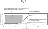
- the switching between adsorption and desorption in the adsorption towers 41a and 41b is performed based on the breakthrough time characteristics of the CO 2 gas in the adsorption tower 41, as shown in Fig. 6 . It is preferable to switch between adsorption and desorption in the adsorption towers 41a and 41b by switching the valves 51 to 53 when the CO 2 concentration (C/C 0 ) at the outlet of one of the adsorption tower 41a and the adsorption tower 41b that is performing adsorption reaches approximately 1/3 (may be within the range of 1/4 or more and 1/2 or less). Switching between adsorption and desorption at this timing can maximize the adsorption and desorption efficiency.
- C 0 represents the maximum amount of CO 2 adsorbed in the adsorption tower.
- the pressure during CO 2 adsorption in the adsorption towers 41a and 41b is preferably adjusted to 5 MPa or more and 45 MPa or less.
- the amount of CO 2 adsorbed to the CO 2 adsorbent depends on the pressure, and increases as the pressure increases, but it is difficult to increase the size of the adsorption tower at high pressure, and thus it is preferable to adjust the pressure to 5 MPa or more and 45 MPa or less.
- the value of 45 MPa is the maximum filling pressure of a 250-L vessel made of chromium molybdenum steel having a wall thickness of 22 mm, and it is not easy to manufacture an adsorption tower having a higher pressure resistance than this.
- the gas discharged from the second CO 2 separation equipment 2 is divided into a treated gas controlled to have a low concentration of CO 2 (low-concentration CO 2 gas) and a high-concentration CO 2 gas having a higher CO 2 concentration than that (high-concentration CO 2 gas), as described below.
- the low-concentration CO 2 gas (treated gas) is discharged by the low-concentration CO 2 gas discharge equipment 60.
- the high-concentration CO 2 gas is refluxed to the first CO 2 separation equipment by the gas reflux equipment 70 (high-concentration CO 2 gas discharge apparatus 45 and reflux pipe 16).
- the low-concentration CO 2 gas discharge equipment 60 and the gas reflux equipment 70 high-concentration CO 2 gas discharge apparatus 45, and reflux pipe 16
- the low-concentration CO 2 gas discharge equipment 60 is equipment configured to discharge low-concentration CO 2 gas after CO 2 is adsorbed by the adsorption separation apparatus 80. That is, the low-concentration CO 2 gas discharge equipment 60 discharges gas containing CO 2 at a concentration lower than the concentration of CO 2 (low-concentration CO 2 gas) in the gas supplied from the pipe 14 to the adsorption separation apparatus 80.
- the low-concentration CO 2 gas discharge equipment 60 is, for example, an apparatus including a flow rate regulator 46 and a pipe 15 (treated gas discharge apparatus).
- the low-concentration CO 2 gas discharged from the second CO 2 separation equipment 2 is discharged from the CO 2 separation system 101 through the valve 53 and the low-concentration CO 2 gas discharge equipment 60.
- the flow rate regulator 46 adjusts the flow rate such that the pressure of the gas in the pipe 15 becomes slightly lower than the pressure during CO 2 adsorption in the towers of the adsorption towers 41a and 41b, and secures the pressure and gas retention time in the adsorption tower 41.
- the treated gas discharged from the low-concentration CO 2 gas discharge equipment 60 has a low CO 2 concentration, and thus the gas is not frozen and not clogged even in a polar region, and can be delivered to a consumption place through a pipeline or the like.
- CO 2 when CO 2 is removed, it is possible to transport many natural gases in the same pipeline, and natural gas transport costs can be reduced.
- the CO 2 concentration in the gas introduced into the adsorption towers 41a and 41b (that is, the gas supplied through the pipe 14) is preferably adjusted to 2 mol% or more and 40 mol% or less by the first CO 2 concentration separation equipment.
- the concentration of CO 2 in the low-concentration CO 2 gas discharged from the low-concentration CO 2 gas discharge equipment 60 is preferably adjusted to 0.5 mol% or more and 10 mol% or less.
- the CO 2 concentration in the gas introduced into the adsorption towers 41a and 41b is more preferably adjusted to 10 mol% or more and 40 mol% or less by the first CO 2 concentration separation equipment.
- the concentration of CO 2 in the low-concentration CO 2 gas discharged from the low-concentration CO 2 gas discharge equipment 60 is more preferably adjusted to 2 mol% or more and 10 mol% or less.
- the concentration of CO 2 in the gas introduced into the adsorption towers 41a and 41b is more preferably adjusted to 2 mol% or more and 10 mol% or less by the first CO 2 separation equipment.
- the concentration of CO 2 in the low-concentration CO 2 gas discharged from the low-concentration CO 2 gas discharge equipment 60 is more preferably adjusted to 0 mol% or more and 2 mol% or less, but may be 0.5 mol% or more and 2 mol% or less.
- the gas reflux equipment 70 includes the high-concentration CO 2 gas discharge apparatus 45 and the reflux pipe 16.
- the reflux pipe 16 a pipe generally used for conveying gas is used.
- the gas reflux equipment 70 functions as an element for returning at least a part of the gas discharged from the high-concentration CO 2 gas discharge apparatus 45 to the first CO 2 separation equipment 1 through the reflux pipe 16.
- the high-concentration CO 2 gas discharge apparatus 45 is an apparatus configured to desorb and discharge CO 2 from the adsorption separation apparatus 80 (adsorption tower 41) after adsorbing CO 2 . That is, the high-concentration CO 2 gas discharge apparatus 45 discharges gas (high-concentration CO 2 gas) containing CO 2 at a concentration higher than the concentration of CO 2 in the low-concentration CO 2 gas discharged by the low-concentration CO 2 gas discharge equipment 60.
- a pump configured to desorb CO 2 from the adsorption separation apparatus 80 by decompression is exemplified as the high-concentration CO 2 gas discharge apparatus 45.
- the high-concentration CO 2 gas is refluxed to the first CO 2 separation equipment 1 through the valve 52 and the gas reflux equipment 70 (the high-concentration CO 2 gas discharge apparatus 45 and the reflux pipe 16), and retreated (that is, cryogenic separation treatment).
- the concentration of CO 2 in the high-concentration CO 2 gas is preferably 50 mol% or more and 99 mol% or less, and more preferably 50 mol% or more and 90 mol% or less. When the concentration of CO 2 in the high-concentration CO 2 gas is adjusted to this range, the efficiency of the CO 2 separation system is improved.
- the concentration of CO 2 in the high-concentration CO 2 gas can be adjusted by the temperature and pressure during CO 2 adsorption in the towers of the adsorption towers 41a and 41b, and the filling rate of rubber as a CO 2 adsorbent.
- a long flow path 42 is provided inside the adsorption tower 41 to secure a residence time, and rubber as a CO 2 adsorbent is disposed in space 43 in the flow path 42.
- a crosslinked body of polydimethylsiloxane As the rubber used as the CO 2 adsorbent, a crosslinked body of polydimethylsiloxane (PDMS) is desirable.
- PDMS polydimethylsiloxane
- a crosslinking method a method using a radical crosslinking agent or a method of crosslinking a plurality of vinyl groups in the molecules of two PDMS by hydrosilation is suitably used. In the latter method, a platinum catalyst is typically used.
- recovered rubber such as waste tires as rubber for a CO 2 adsorbent.
- the glass transition temperature of the rubber is desirably -150°C or more and -10°C or less
- the SP value at room temperature is desirably 7.0 (cal/cm 3 ) 0.5 or more and 10.0 (cal/cm 3 ) 0.5 or less.
- the elastic modulus at 25°C is preferably 0.03 MPa or more and 8 MPa or less. Rubber under these conditions has a high amount of CO 2 adsorbed and adsorption-desorption efficiency.
- Fig. 7 The relationship between the absolute pressure and the amount of CO 2 adsorbed at a temperature of 245 K when the PDMS rubber was used is illustrated in Fig. 7 .
- This rubber has a glass transition temperature of -150°C, an SP value of 7.5 (cal/cm 3 ) 0.5 at room temperature, and an elastic modulus of about 4 MPa at 25°C.
- Favorable CO 2 adsorption characteristics are found to be exhibited.
- a rubber having an SP value of 10.5 (cal/cm 3 ) 0.5 or less at room temperature is generally hydrophobic, but some rubbers are likely to adsorb water.
- making the rubber hydrophobic allows a large amount of CO 2 to be absorbed below the freezing point. Below the freezing point, water is likely to be adsorbed to the rubber interface and the void portion, and the adsorption performance is likely to be deteriorated by slight mixing of water.
- a hydrophobic molecule such as decane may be adsorbed to the rubber. As a result, adsorption of water is suppressed, and a high adsorption power of CO 2 is easily maintained.
- the contact angle of water on the surface of the CO 2 adsorbent may be 80° or more and 150° or less.
- the SP value of rubber at room temperature is close to the SP value of CO 2 , but it is known that the SP value of CO 2 increases as the temperature decreases.
- the SP value of the rubber also increases with a decrease in temperature, but the increase in the SP value of the PDMS rubber is slightly lower than the increase in the SP of CO 2 .
- a rubber having a slightly larger SP value than the PDMS rubber is desirable.
- examples of such a rubber include a rubber obtained by substituting a methyl group in a molecule of a PDMS rubber with a phenyl group or the like.
- forming the above rubber into a powder shape or a fine particle shape increases the surface area, and CO 2 can be quickly absorbed.
- rubber such as PDMS that is pulverized or micronized to a size of 500 ⁇ m or less can be preferably used.
- pellet-shaped rubber can be easily handled for replacement work and the like and can be preferably used.
- the thickness of the pellet-shaped rubber is preferably 5 mm or less.
- the lower limit of the thickness of the rubber is not particularly limited, but is preferably 0.1 mm or more from the viewpoint of ease of handling and stability of quality. Therefore, when the rubber is formed into a pellet shape, the thickness thereof is preferably 0.1 mm or more and 5 mm or less.
- the desorption of CO 2 using rubber can be achieved by reducing the pressure, and heating is not required, thus providing a feature of small energy consumption.
- the rubber is packed in a mesh or porous bag and provided in the adsorption tower 41.
- the adsorption separation apparatus 80 may have the first adsorption tower group including a plurality of adsorption towers 41a and the second adsorption tower group including a plurality of adsorption towers 41b.
- first adsorption tower group for example, a plurality of adsorption towers 41a are disposed in series.
- second adsorption tower group for example, a plurality of adsorption towers 41b are disposed in series.
- the adsorption separation apparatus 80 includes the first adsorption tower group and the second adsorption tower group, the adsorption amount of CO 2 and the adsorption efficiency are improved. Fig.
- each adsorption tower group includes three or more adsorption towers 41, it is not necessary to directly connect all of the three or more adsorption towers 41, and some of the adsorption towers 41 (that is, two or more adsorption towers 41) may be connected in series.
- the first adsorption tower group and the second adsorption tower group are preferably a pair of adsorption tower groups having the same configuration. That is, it is preferable that the first adsorption tower group and the second adsorption tower group have the same number of adsorption towers and the same disposition of adsorption towers as well as the internal configuration of each adsorption tower.
- rubber is used as the CO 2 adsorbent, and a powder shape or a fine particle shape is preferably used for improving the adsorption amount and adsorption efficiency.
- the gap region between the rubbers is large and the pressure during adsorption is a high pressure of 5 MPa or more and 45 MPa or less, and thus a desired gas such as methane is likely to be trapped therein. That is, there arises a problem such that the recovery rate of a desired gas is likely to decrease.
- gas reflux equipment 70 including the high-concentration CO 2 gas discharge apparatus 45 and the reflux pipe 16 is provided, and gas containing high-concentration CO 2 is retreated using a cryogenic separation apparatus that is the first CO 2 separation equipment 1 to increase a recovery rate of a desired gas.
- This treatment causes a desired gas recovery rate to be 90% or more.
- the gas reflux equipment 70 includes the reflux pipe 16.
- a pump is used as the high-concentration CO 2 gas discharge apparatus 45, but various apparatuses can be used as the high-concentration CO 2 gas discharge apparatus 45.
- a compressor a type of pump
- a pump when a pump is used as the high-concentration CO 2 gas discharge apparatus 45, sending the heat medium to the second CO 2 separation equipment 2 also increases the temperature of the adsorption tower, thereby sending the desorbed CO 2 to the first CO 2 separation equipment 1.
- the gas reflux equipment 70 may include, for example, a pump (compressor), a heating apparatus, or both a pump (compressor) and a heating apparatus in addition to the reflux pipe 16.
- the gas can be refluxed by applying heat to the adsorption separation apparatus 80 by the heating apparatus.
- a compressor capable of reducing the pressure inside the adsorption tower of the second CO 2 separation equipment 2 is suitably used.
- a CO 2 separation system using rubber as an adsorbent is characterized by being capable of separating high-concentration CO 2 and requiring less energy for the separation than a chemical absorption method using an amine solvent. Further, the desired gas recovery rate is high due to the reflux of the above gas containing high concentration of CO 2 .
- the CO 2 separation system of the present invention makes it possible to transport natural gas obtained in the polar region by pipeline at low cost.
- Biogas also generally contains a high concentration of CO 2 , and thus the CO 2 separation system of the present invention is also effective for treating biogas.
- CO 2 was separated from the gas to be treated by the following CO 2 separation system using a mixed gas of CO 2 and N 2 as the gas to be treated.
- the CO 2 separation system according to the embodiment was configured by the following elements.
- the following elements are connected through piping.
- the first cooling apparatus, the third cooling apparatus, and the CO 2 recovery container described above are examples of the first CO 2 separation equipment (cryogenic separation apparatus), and the above column is an example of the second CO 2 separation equipment.
- a CO 2 adsorption test and a CO 2 desorption-recovery test were performed using the above CO 2 separation system.
- the piping connection after the column is different between the CO 2 adsorption test and the CO 2 desorption-recovery test, and is switched by a valve provided in the pipe immediately after the column.
- the column is connected to the gas chromatograph through a flowmeter for controlling the column pressure during the CO 2 adsorption test, and is connected to the CO 2 recovery container during the CO 2 desorption-recovery.
- the pressure of the gas to be treated was adjusted with a secondary pressure gauge of a regulator.
- the gas to be treated was flowed through the first cooling apparatus configured to remove moisture, and the gas with moisture removed was supplied to the column.
- KMP-602 manufactured by Shin-Etsu Chemical Co., Ltd. was used as a CO 2 adsorbent.
- CO 2 had 20 mol%
- N 2 had 80 mol%.
- the column pressure was 6 MPa
- the column temperature was -30°C. Specifically, first, the column temperature was maintained at -30°C by the second cooling apparatus, only N 2 was flowed into the column, and the flow velocity of the column flowmeter for controlling the column pressure was set to 0 to increase the column pressure to 6 MPa.
- the flow rate of the supplied gas was adjusted to 40 sccm and 120 sccm by a gas flowmeter connected to a CO 2 gas cylinder and a N 2 gas cylinder, respectively, the gas to be treated in which these were mixed was flown into the column, and at the same time, the flow rate of the column flowmeter for controlling the column pressure was adjusted to 200 sccm to start the CO 2 adsorption test, the CO 2 concentration for a predetermined time was measured by a chromatograph, and the amount of CO 2 adsorbed was calculated.
- the separation system of the present invention it is desirable to forcibly move the high-concentration CO 2 gas discharged from the column to the cryogenic separation apparatus using a pump, more specifically, a compressor as a high-concentration CO 2 gas discharge apparatus that is a component of the gas reflux equipment.
- a pump more specifically, a compressor as a high-concentration CO 2 gas discharge apparatus that is a component of the gas reflux equipment.
- the gas cannot be stably moved by pressurization by the compressor, and thus in the present embodiment, in order to achieve pressure-driven mass transfer (gas transfer) similar to that of the compressor, the reflux is performed to the cryogenic separation apparatus by increasing the temperature of the CO 2 adsorption tower.
- Fig. 8 is a breakthrough curve in Example 1.
- the amount of CO 2 adsorbed was 1.8 g from the area of the shaded portion in Fig. 8 , and satisfactory adsorption characteristics were exhibited at a breakthrough time of 23 minutes with respect to the target value of 5 to 60 minutes.
- Table 1 shows the results of the CO 2 adsorption test and the CO 2 desorption-recovery test.
- the pressure of the column and the recovery container during CO 2 desorption-recovery was 2.9 MPa, the CO 2 desorption-recovery amount was 1.3 g, and the recovery rate was 72 mol%, indicating that a sufficiently high concentration of CO 2 was recovered.
- CO 2 is liquefied at -40°C and 1 MPa, and thus the desorbed and recovered CO 2 is considered to be liquefied CO 2 .
- Example 1 exhibited favorable adsorption characteristics with an adsorption amount of 1.8 g at a breakthrough time of 23 minutes under the conditions of an adsorption pressure of 6 MPa and a CO 2 concentration of the gas to be treated of 20 mol%.
- the temperature during desorption-recovery was -40°C, and the liquefied CO 2 recovery rate was 72%, indicating favorable desorption-recovery characteristics.
- [Table 1] Item Amount of CO 2 adsorbed (g) Amount of CO 2 recovered (g) Recovery rate of CO 2 (mol%) Target value - - 50 ⁇ 99
- Example 1 1.8 1.3 72
- Example 2 A pulverized product of K-125 manufactured by TOGAWA RUBBER CO., LTD. was used as a CO 2 adsorbent.
- a desorption experiment of 1.8 g of CO 2 adsorbed was performed using the same apparatus as in Example 1.
- Table 2 shows the results of the CO 2 adsorption test and the CO 2 desorption-recovery test.
- the pressure of the column and the recovery container during CO 2 desorption-recovery was 1.0 MPa, the CO 2 desorption-recovery amount was 1.7 g, and the recovery rate was 94 mol%, indicating that a significantly high concentration of CO 2 was recovered.
- Item Amount of CO 2 adsorbed (g) Amount of CO 2 recovered (g) Recovery rate of CO 2 (mol%) Target value - - 50 ⁇ 99
- Example 2 1.8 1.7 94
- the present invention can efficiently remove CO 2 from natural gas, biogas, and the like containing a large amount of CO 2 .
- this can treat natural gas or the like containing a high concentration of CO 2 at low cost, allowing inexpensive supply to the pipeline.
- the present invention can achieve effective use of gas that has been difficult to use so far, and is considered to greatly contribute to industrial and social development.
- CO 2 separation system that separates CO 2 from natural gas containing CO 2 at a high concentration of 30% or more, and supplies CO 2 at 2% or less.
- Natural gas containing a large amount of CO 2 has a problem of freezing in a low temperature zone such as a polar region.
- natural gas containing 2% or more of CO 2 corrodes the pipeline.
- the use of the CO 2 separation system of the present invention efficiently treats natural gas containing a high concentration of CO 2 at low cost, allowing inexpensive transportation to the pipeline.
Landscapes
- Engineering & Computer Science (AREA)
- Chemical & Material Sciences (AREA)
- Chemical Kinetics & Catalysis (AREA)
- Mechanical Engineering (AREA)
- Oil, Petroleum & Natural Gas (AREA)
- General Chemical & Material Sciences (AREA)
- Physics & Mathematics (AREA)
- Thermal Sciences (AREA)
- General Engineering & Computer Science (AREA)
- Organic Chemistry (AREA)
- Analytical Chemistry (AREA)
- Inorganic Chemistry (AREA)
- Separation Of Gases By Adsorption (AREA)
Abstract
A CO2 separation system, including: first CO2 separation equipment 1; second CO2 separation equipment 2; a first pipe 14; low-concentration CO2 gas discharge equipment 60; and gas reflux equipment 70 including a second pipe 16 and a high-concentration CO2 gas discharge apparatus 45, wherein the first CO2 separation equipment 1 includes a cryogenic separation apparatus configured to separate CO2 from gas to be treated by cryogenic separation treatment, the first pipe 14 supplies gas discharged from the first CO2 separation equipment 1 to the second CO2 separation equipment 2, the second CO2 separation equipment 2 includes an adsorption separation apparatus including rubber as a CO2 adsorbent, the low-concentration CO2 gas discharge equipment 60 discharges gas containing low concentration CO2 from the second CO2 separation equipment 2, the high-concentration CO2 gas discharge apparatus 45 discharges gas containing CO2 having a concentration higher than the low concentration from the second CO2 separation equipment 2, in the gas reflux equipment 70, at least a part of the gas discharged from the high-concentration CO2 gas discharge apparatus 45 is returned to the first CO2 separation equipment 1 through the second pipe 16, and the first CO2 separation equipment 1 performs cryogenic separation treatment for separating CO2 from the gas returned by the gas reflux equipment 70.
Description
- The present invention relates to a CO2 separation system.
- From the viewpoint of reducing greenhouse gas emissions in consideration of desorption energy efficiency, it is earnestly desired to separate and recover CO2 from natural gas or associated gas containing a high concentration of CO2 with low energy.
- In general, the separation process of natural gas and associated gas can be classified as follows by CO2 concentration.
- (1) Case of 2% or less of CO2 concentration
In this case, it is not always necessary to separate CO2. This is because when the CO2 concentration is 2% or less, the influence of corrosion of the pipeline is small. However, when liquefied natural gas (LNG) is produced, the acid gas removal (AGR) process is applied before the application of the cryogenic separation method. - (2) Case of around 30% of CO2 concentration
In older equipment, molten potassium carbonate has been used, but is being replaced with the AGR process using amine solvents. The amine solvent can cause the adsorbent to be regenerated by heat, leading to easy maintenance of equipment. On the other hand, in molten potassium carbonate, corrosion of a steel material is often a problem. - (3) Case of 30 to 60% of CO2 concentration
As the adsorbent (sorbent), an organic solvent such as propylene carbonate (PC) is used. When the CO2 concentration is high, a large amount of thermal energy is required for regeneration of the amine solvent, and thus the AGR process is not available. - (4) Case of 70% or more of CO2 concentration
At present, development is difficult, and expectations for a novel CO2 separation technology are high. - Under such circumstances, in the development of natural gas, it is required to separate CO2 having a high concentration of 30% or more into a lower concentration of 2% or less. In addition, not only natural gas but also mixed gas containing high concentration CO2 is generated in thermal power plants, production of biogas, and the like, and low cost recovery technology is expected.
- The method for recovering CO2 using an organic solvent as an adsorbent (sorbent) is problematic in that energy loss is large because it is necessary to dissolve the mixed gas into high pressure microbubbles, and a recovery cost of the volatilized organic solvent is also required because a part of the organic solvent is volatilized.
- Patent Literature 1:
Japanese Unexamined Utility Model Publication No. 61-15489 -
- Non Patent Literature 1: Jun Matsumoto et al., Journal of the Japanese Association for Petroleum Technology, Vol. 76, No. 6, pp. 512-516 (November 2011)
- Non Patent Literature 2: Zenji Fujiyasu, Cryogenic Engineering, Vol. 5, No. 4, pp. 181-185 (1970)
- Non Patent Literature 3: Shigeru Kimura, Hitachi Review, Vol. 48, No. 8, pp. 69-74 (August 1966)
- Non Patent Literature 4: Izumi Ichinose, et al., JACI GSC Symposium (June 15 to 16, 2022)
- In view of the above background, an object of the present invention is to provide a CO2 separation system that efficiently separates CO2 from natural gas, biogas, and the like containing high concentration CO2 with low energy and supplies a desired gas such as methane.
- The configuration of the present invention will be described below.
- A CO2 separation system, including: first CO2 separation equipment; second CO2 separation equipment; a first pipe; low-concentration CO2 gas discharge equipment; gas reflux equipment including a second pipe and a high-concentration CO2 gas discharge apparatus, wherein the first CO2 separation equipment includes a cryogenic separation apparatus configured to separate CO2 from gas to be treated by cryogenic separation treatment, the first pipe supplies gas discharged from the first CO2 separation equipment to the second CO2 separation equipment, the second CO2 separation equipment includes an adsorption separation apparatus including rubber as a CO2 adsorbent, the low-concentration CO2 gas discharge equipment discharges gas containing low concentration CO2 from the second CO2 separation equipment, the high-concentration CO2 gas discharge apparatus discharges gas containing CO2 having a concentration higher than the low concentration from the second CO2 separation equipment, in the gas reflux equipment, at least a part of the gas discharged from the high-concentration CO2 gas discharge apparatus is returned to the first CO2 separation equipment through the second pipe, and the first CO2 separation equipment performs cryogenic separation treatment for separating CO2 from the gas returned by the gas reflux equipment.
- The CO2 separation system according to the
configuration 1, wherein the second CO2 separation equipment includes a first adsorption tower group including one or more adsorption towers and a second adsorption tower group including one or more adsorption towers, the adsorption tower has a flow path through which gas flows while being retained therein, and the CO2 adsorbent, and the CO2 separation system further includes a cooling means capable of cooling the flow path and the CO2 adsorbent. - The CO2 separation system according to the
configuration 2, wherein the first adsorption tower group and the second adsorption tower group are adsorption tower groups forming a pair in the same configuration. - The CO2 separation system according to the
configuration 2, wherein at least a part of the adsorption towers constituting the first adsorption tower group and the second adsorption tower group is disposed in series in the first adsorption tower group and the second adsorption tower group. - The CO2 separation system according to the
configuration 2, wherein a gas breakthrough time per adsorption tower is 5 minutes or more and 60 minutes or less. - The CO2 separation system according to any one of
configurations 2 to 5, wherein a CO2 concentration in gas introduced into the first adsorption tower group and the second adsorption tower group is adjusted to 10 mol% or more and 40 mol% or less, and a CO2 concentration in gas discharged from the first adsorption tower group and the second adsorption tower group is adjusted to 2 mol% or more and 10 mol% or less. - The CO2 separation system according to any one of
configurations 2 to 5, wherein a CO2 concentration in gas introduced into the first adsorption tower group and the second adsorption tower group is adjusted to 5 mol% or more and 10 mol% or less, and a CO2 concentration in gas discharged from the first adsorption tower group and the second adsorption tower group is adjusted to 0 mol% or more and 2 mol% or less. - The CO2 separation system according to any one of
configurations 2 to 7, wherein an adsorption pressure of the adsorption tower is adjusted to 5 MPa or more and 45 MPa or less. - The CO2 separation system according to the
configuration 2, wherein a temperature of the cooling is -50°C or more and 0°C or less. - The CO2 separation system according to the
configuration 1, wherein a CO2 concentration of the high concentration is 50 mol% or more and 99 mol% or less. - The CO2 separation system according to any one of
configurations 1 to 10, wherein the rubber is provided in one or more states selected from the group consisting of a pellet shape, a powder shape, and a fine particle shape. - The CO2 separation system according to the
configuration 11, wherein the rubber is provided by being packed in a mesh or porous bag. - The CO2 separation system according to the
configuration 1, wherein the cryogenic separation apparatus includes: a compression apparatus configured to compress supplied gas; a cooling apparatus configured to cool gas introduced through the compression apparatus; and an apparatus configured to discharge CO2 liquefied by being subjected to the cooling. - The CO2 separation system according to the
configuration 1, wherein the gas to be treated is introduced into the cryogenic separation apparatus through decompression equipment configured to decompress gas to separate liquid CO2. - The CO2 separation system according to any one of
configurations 1 to 14, wherein the gas to be treated is introduced into the cryogenic separation apparatus through dehydration equipment configured to perform dehydration. - The present invention provides a CO2 separation system configured to efficiently separate CO2 from natural gas, biogas, or the like containing a high concentration of CO2 with low energy and supply a desired gas such as methane.
-
-
Fig. 1 is a system configuration view showing an overall configuration of a CO2 separation system of the present invention. -
Fig. 2 is a configuration view showing a configuration of first CO2 separation equipment that is a part of the CO2 separation system of the present invention. -
Fig. 3 is a configuration view showing a configuration of second CO2 separation equipment that is a part of the CO2 separation system of the present invention. -
Fig. 4 is a cross-sectional view showing a structure of an adsorption tower. -
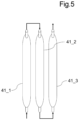
Fig. 5 is an explanatory view for explaining a configuration of an adsorption tower. -
Fig. 6 is a characteristic view showing adsorption and desorption characteristics of CO2 using rubber. -
Fig. 7 is a characteristic view showing a relationship between an absolute pressure and an amount of CO2 adsorbed. -
Fig. 8 is a view showing a breakthrough curve according to Examples. - The CO2 separation system according to the present embodiment will be described with reference to
Figs. 1 ,2 , and3 . - As illustrated in
Fig. 1 , the CO2 separation system 101 of the present embodiment includes first CO2 separation equipment 1 that is a cryogenic separation apparatus, second CO2 separation equipment 2, a pipe 14 (exemplified as a "first pipe"), low-concentration CO2gas discharge equipment 60, andgas reflux equipment 70 including a reflux pipe 16 (exemplified as a "second pipe") and a high-concentration CO2gas discharge apparatus 45.Fig. 1 illustrates a configuration in which the CO2 separation system 101 further includes decompression equipment 4,dehydration equipment 5, andpipes 11 to 13. - However, it is not essential for the CO2 separation system 101 to include the decompression equipment 4 and the
dehydration equipment 5. Both or any one of the decompression equipment 4 and thedehydration equipment 5 may be omitted from the CO2 separation system 101. Hereinafter, gas from which CO2 is to be separated by the CO2 separation system 101 is referred to as a "gas to be treated". The gas to be treated is, for example, natural gas or associated gas, and contains CO2 in addition to a desired component (for example, methane). - Herein, the first CO2 separation equipment 1 and the second CO2 separation equipment 2 are connected to the
cooling equipment 3. Thecooling equipment 3 is capable of efficiently and precisely cooling the first CO2 separation equipment 1 and the second CO2 separation equipment 2. Thecooling equipment 3 is not particularly limited, but examples thereof include a vapor compression refrigerator, and a cooling medium is not particularly limited, but CO2 can be used. - The gas to be treated is supplied to the first CO2 separation equipment 1 through, for example, the decompression equipment 4 and the
dehydration equipment 5. First, the gas to be treated is supplied to the decompression equipment 4 through thepipe 11. Then, the gas to be treated that has passed through the decompression equipment 4 is supplied to thedehydration equipment 5 through thepipe 12. Then, the gas to be treated that has passed through thedehydration equipment 5 is supplied to the first CO2 separation equipment 1 through thepipe 13. - The first CO2 separation equipment 1 is connected to the
second separation equipment 2 through thepipe 14. Areflux pipe 16 for refluxing a part of the gas treated in thesecond separation equipment 2 to thefirst separation equipment 1 is connected to thesecond separation equipment 2 and thefirst separation equipment 1. Further, the first CO2 separation equipment 1 includes adischarge pipe 17 configured to discharge liquid CO2 generated by treatment in the first CO2 separation equipment 1 and liquid of other condensable gases. - The decompression equipment 4 is equipment provided for the purpose of decompressing gas to be treated having a high pressure of 60 MPa or more (for example, a high pressure gas welling up from deep in the ground), and includes, for example, a choke and a temperature adjusting apparatus. When the gas to be treated has an initial pressure of, for example, nearly 120 MPa and contains water, rapid cooling by pressure reduction causes methane hydride to be formed, and thus preventing this requires a temperature adjusting apparatus. In a normal decompression operation, the pressure is often reduced stepwise from 120 MPa to 60 MPa, 15 MPa, 3 MPa, or the like, for example, while the temperature is maintained at room temperature or more. When the gas to be treated contains a large amount of CO2, the decompression equipment 4 generates liquid CO2 by appropriate decompression, and thus may include a pipe configured to discharge CO2. In addition, in the decompression equipment 4, water or condensate (liquid hydrocarbon) may be generated by cooling, and water or condensate can also be discharged from a pipe configured to discharge CO2. When the gas to be treated is natural gas containing a condensate, it is desirable to discharge the condensate as a valuable material.
- The
dehydration equipment 5 is equipment provided for the purpose of removing moisture in the gas to be treated. Thedehydration equipment 5 has a removing agent for removing moisture in the gas to be treated. As the agent for removing water, molecular sieve (zeolite, registered trademark), silica gel, activated carbon, activated alumina, ethylene glycol derivative, and the like can be used. In particular, thedehydration equipment 5 using silica gel or activated alumina capable of achieving a dew point of about -40°C can be suitably used. The water in the gas to be treated becomes substantially liquid by lowering the temperature, and thedehydration equipment 5 is used to remove moisture in the gas phase that does not aggregate even around room temperature. Although not illustrated, thedehydration equipment 5 includes a heater and a cooler for desorption vapor in order to regenerate the agent for removing water. In addition, thedehydration equipment 5 is desirably operated at 0°C or more in order to prevent the formation of the hydride. In addition, in the case of continuous operation, thedehydration equipment 5 is one including a plurality of adsorption towers. For example, thedehydration equipment 5 is provided when the gas to be treated is natural gas. - The first CO2 separation equipment 1 is an apparatus configured to perform cryogenic separation treatment for separating CO2 from gas to be treated. As the first CO2 separation equipment 1, a generally used cryogenic separation apparatus can be used except for having a path in which at least a part of the gas refluxed through the
reflux pipe 16 is treated by the first CO2 separation equipment 1. -
Fig. 2 is a configuration view according to an example of the first CO2 separation equipment 1 of the present embodiment. As illustrated inFig. 2 , the first CO2 separation equipment 1 includes, for example, acompression apparatus 21, adehydration apparatus 22, acooling apparatus 23, and a liquefied CO2 discharge apparatus 24. - A
pipe 13 configured to supply the gas to be treated and areflux pipe 16 to which the gas to be refluxed from the second CO2 separation equipment 2 is supplied are connected to acompression apparatus 21. The gas compressed by thecompression apparatus 21 is supplied to adehydration apparatus 22 through apipe 31. Herein, the pressure of the gas after the compression treatment is, for example, 10 MPa or more and 50 MPa or less. The temperature increases when the gas is compressed, and thus the first CO2 separation equipment 1 preferably includes acooling apparatus 23. - The
dehydration apparatus 22 is an apparatus that performs a dry gasification treatment (dehydration treatment) of removing moisture from the gas after the compression treatment. As a method for the dry gasification treatment, a method using silica gel or zeolite is excellent. Herein, the amount of water contained in the dry gas subjected to the dry gasification treatment is preferably controlled to 10 ppm or less. Dehydration on silica gel is desirably performed at 30°C or less because the adsorption amount decreases at high temperatures. When sufficient dehydration is performed in thedehydration equipment 5, thedehydration apparatus 22 can be omitted. - The gas subjected to the dry gasification treatment is supplied to the
cooling apparatus 23 through thepipe 32. Herein, thecooling apparatus 23 is not particularly limited, but for example, a vapor compression refrigerator using CO2 as a cooling medium is used, and cold heat thereof can be used. In addition, cooling by adiabatic expansion can be used as long as solidification of CO2 does not occur. - The
cooling apparatus 23 cools the supplied gas to -40°C or more and 0°C or less. The gas supplied to thecooling apparatus 23 is already dehydrated and no hydrate is formed, and thus the temperature of thecooling apparatus 23 is desirably low within a range in which solidification of CO2 does not occur. In addition, the pressure is 10 MPa or more and 50 MPa or less, but it is desirable that the pressure is high within a range in which the safety of the pressure-resistant container can be secured. The cooled gas is conveyed to a liquefied CO2 discharge apparatus 24 through apipe 33, and a liquid material such as liquid CO2 generated by cooling is discharged through adischarge pipe 17. - The liquefied CO2 discharge apparatus 24 is a pump configured to discharge liquid CO2, and needs to be cooled in
cooling equipment 3 similarly to thecooling apparatus 23. -
Fig. 3 is a configuration view according to an example of the second CO2 separation equipment 2 according to the present embodiment. The second CO2 separation equipment 2 is equipment configured to remove CO2 that has not been completely separated by the cryogenic separation treatment in the first CO2 separation equipment 1. As shown inFig. 3 , the second CO2 separation equipment 2 includes anadsorption separation apparatus 80 including rubber as an adsorbent. - The
adsorption separation apparatus 80 is a device that adsorbs and separates CO2 in the gas supplied from thepipe 14, and desorbs CO2. Specifically, theadsorption separation apparatus 80 includes two towers of the adsorption towers 41 (adsorption towers 41a and 41b) that incorporate, for example, rubber, which will be described later, as a CO2 adsorbent. When there is no need to distinguish between theadsorption tower 41a and theadsorption tower 41b, they will be referred to as theadsorption tower 41. The number of theadsorption tower 41 included in theadsorption separation apparatus 80 is not limited to two towers, and may be three or more towers, or may be one tower. From the viewpoint of continuously treating the gas to be treated, the number of theadsorption tower 41 is preferably two or more. - As described above, the
adsorption tower 41 incorporates rubber as a CO2 adsorbent and adsorbs and desorbs CO2. The adsorption towers 41a and 41b are identical and disposed in pairs. - The gas treated in the first CO2 separation equipment 1 is introduced through a
pipe 14 and avalve 51 into either theadsorption tower 41a or theadsorption tower 41b. Theadsorption tower 41a andadsorption tower 41b are connected to areflux pipe 16 through avalve 52 and a high-concentration CO2gas exhaust apparatus 45. In addition, theadsorption tower 41a andadsorption tower 41b are connected to apipe 15 through avalve 53 and aflow rate regulator 46. Switchingvalves adsorption tower 41a, and CO2 adsorption and CO2 desorption are alternately performed in theadsorption tower 41b. - The method of CO2 adsorption and desorption in the
adsorption tower 41 will be specifically described below. Thevalve 51 is opened to theadsorption tower 41a side and closed to theadsorption tower 41b side, thevalve 52 is closed to theadsorption tower 41a side and opened to theadsorption tower 41b side, and thevalve 53 is opened to theadsorption tower 41a side and closed to theadsorption tower 41b side, whereby theadsorption tower 41a is operated for CO2 adsorption and theadsorption tower 41b is operated for CO2 desorption. Thereafter, thevalve 51 is closed to theadsorption tower 41a side and opened to theadsorption tower 41b side, thevalve 52 is opened to theadsorption tower 41a side and closed to theadsorption tower 41b side, and thevalve 53 is closed to theadsorption tower 41a side and opened to theadsorption tower 41b side, whereby theadsorption tower 41a is operated for CO2 desorption and theadsorption tower 41b is operated for CO2 adsorption. This treatment is then repeated to perform CO2 adsorption and desorption. Herein, the adsorption and desorption are controlled by pressure. Theadsorption tower 41a andadsorption tower 41b are thermally insulated, but thecooling equipment 3 is used for pre-cooling and maintaining a low temperature. Herein, the temperature inside the adsorption towers 41a and 41b during adsorption is preferably -50°C or more and 0°C or less, and more preferably -40°C or more and -20°C or less. Thecooling equipment 3 is an example of a cooling means capable of cooling a flow path (aflow path 42 described below) through which gas flows while being retained therein, and the CO2 adsorbent. Controlling the temperature inside the adsorption towers 41a and 41b during adsorption within this range can prevent solidification of CO2 during desorption, and the effect of improving separation efficiency can be obtained. The temperature of theadsorption tower 41 of the second CO2 separation equipment is desirably lower than the temperature of the first CO2 separation equipment (cryogenic separation apparatus). This is because the second CO2 separation equipment has a lower CO2 concentration in the gas compared to the first CO2 separation equipment, making solidification of CO2 less likely to occur, and the lower temperature results in higher CO2 separation efficiency in theadsorption tower 41. - It is preferable that the switching between adsorption and desorption in the adsorption towers 41a and 41b (switching of the
valves adsorption tower 41, as shown inFig. 6 . It is preferable to switch between adsorption and desorption in the adsorption towers 41a and 41b by switching thevalves 51 to 53 when the CO2 concentration (C/C0) at the outlet of one of theadsorption tower 41a and theadsorption tower 41b that is performing adsorption reaches approximately 1/3 (may be within the range of 1/4 or more and 1/2 or less). Switching between adsorption and desorption at this timing can maximize the adsorption and desorption efficiency. C0 represents the maximum amount of CO2 adsorbed in the adsorption tower. - The pressure during CO2 adsorption in the adsorption towers 41a and 41b is preferably adjusted to 5 MPa or more and 45 MPa or less. The amount of CO2 adsorbed to the CO2 adsorbent depends on the pressure, and increases as the pressure increases, but it is difficult to increase the size of the adsorption tower at high pressure, and thus it is preferable to adjust the pressure to 5 MPa or more and 45 MPa or less. The value of 45 MPa is the maximum filling pressure of a 250-L vessel made of chromium molybdenum steel having a wall thickness of 22 mm, and it is not easy to manufacture an adsorption tower having a higher pressure resistance than this.
- The gas discharged from the second CO2 separation equipment 2 (adsorption tower 41) is divided into a treated gas controlled to have a low concentration of CO2 (low-concentration CO2 gas) and a high-concentration CO2 gas having a higher CO2 concentration than that (high-concentration CO2 gas), as described below. The low-concentration CO2 gas (treated gas) is discharged by the low-concentration CO2
gas discharge equipment 60. On the other hand, the high-concentration CO2 gas is refluxed to the first CO2 separation equipment by the gas reflux equipment 70 (high-concentration CO2gas discharge apparatus 45 and reflux pipe 16). Hereinafter, the low-concentration CO2gas discharge equipment 60 and the gas reflux equipment 70 (high-concentration CO2gas discharge apparatus 45, and reflux pipe 16) will be described in detail. - The low-concentration CO2
gas discharge equipment 60 is equipment configured to discharge low-concentration CO2 gas after CO2 is adsorbed by theadsorption separation apparatus 80. That is, the low-concentration CO2gas discharge equipment 60 discharges gas containing CO2 at a concentration lower than the concentration of CO2 (low-concentration CO2 gas) in the gas supplied from thepipe 14 to theadsorption separation apparatus 80. - Specifically, the low-concentration CO2
gas discharge equipment 60 is, for example, an apparatus including aflow rate regulator 46 and a pipe 15 (treated gas discharge apparatus). The low-concentration CO2 gas discharged from the second CO2 separation equipment 2 is discharged from the CO2 separation system 101 through thevalve 53 and the low-concentration CO2gas discharge equipment 60. Theflow rate regulator 46 adjusts the flow rate such that the pressure of the gas in thepipe 15 becomes slightly lower than the pressure during CO2 adsorption in the towers of the adsorption towers 41a and 41b, and secures the pressure and gas retention time in theadsorption tower 41. The treated gas discharged from the low-concentration CO2gas discharge equipment 60 has a low CO2 concentration, and thus the gas is not frozen and not clogged even in a polar region, and can be delivered to a consumption place through a pipeline or the like. In addition, when CO2 is removed, it is possible to transport many natural gases in the same pipeline, and natural gas transport costs can be reduced. - Herein, the CO2 concentration in the gas introduced into the adsorption towers 41a and 41b (that is, the gas supplied through the pipe 14) is preferably adjusted to 2 mol% or more and 40 mol% or less by the first CO2 concentration separation equipment. The concentration of CO2 in the low-concentration CO2 gas discharged from the low-concentration CO2
gas discharge equipment 60 is preferably adjusted to 0.5 mol% or more and 10 mol% or less. The CO2 concentration in the gas introduced into the adsorption towers 41a and 41b is more preferably adjusted to 10 mol% or more and 40 mol% or less by the first CO2 concentration separation equipment. The concentration of CO2 in the low-concentration CO2 gas discharged from the low-concentration CO2gas discharge equipment 60 is more preferably adjusted to 2 mol% or more and 10 mol% or less. When the CO2 concentration in the gases introduced into the adsorption towers 41a and 41b and the CO2 concentration in the low-concentration CO2 gas discharged from the low-concentration CO2gas discharge equipment 60 are adjusted to the concentrations in this range, a large reduction effect of the greenhouse gas can be obtained. - Alternatively, the concentration of CO2 in the gas introduced into the adsorption towers 41a and 41b is more preferably adjusted to 2 mol% or more and 10 mol% or less by the first CO2 separation equipment. The concentration of CO2 in the low-concentration CO2 gas discharged from the low-concentration CO2
gas discharge equipment 60 is more preferably adjusted to 0 mol% or more and 2 mol% or less, but may be 0.5 mol% or more and 2 mol% or less. When the concentration of CO2 in the gas introduced into the adsorption towers 41a and 41b and the concentration of CO2 in the low-concentration CO2 gas discharged from the low-concentration CO2gas discharge equipment 60 are adjusted to the concentrations in this range, the corrosion prevention effect of the pipeline is obtained. - As described above, the
gas reflux equipment 70 includes the high-concentration CO2gas discharge apparatus 45 and thereflux pipe 16. As thereflux pipe 16, a pipe generally used for conveying gas is used. Specifically, thegas reflux equipment 70 functions as an element for returning at least a part of the gas discharged from the high-concentration CO2gas discharge apparatus 45 to the first CO2 separation equipment 1 through thereflux pipe 16. - The high-concentration CO2
gas discharge apparatus 45 is an apparatus configured to desorb and discharge CO2 from the adsorption separation apparatus 80 (adsorption tower 41) after adsorbing CO2. That is, the high-concentration CO2gas discharge apparatus 45 discharges gas (high-concentration CO2 gas) containing CO2 at a concentration higher than the concentration of CO2 in the low-concentration CO2 gas discharged by the low-concentration CO2gas discharge equipment 60. In the present embodiment, a pump configured to desorb CO2 from theadsorption separation apparatus 80 by decompression is exemplified as the high-concentration CO2gas discharge apparatus 45. - The high-concentration CO2 gas is refluxed to the first CO2 separation equipment 1 through the
valve 52 and the gas reflux equipment 70 (the high-concentration CO2gas discharge apparatus 45 and the reflux pipe 16), and retreated (that is, cryogenic separation treatment). The concentration of CO2 in the high-concentration CO2 gas is preferably 50 mol% or more and 99 mol% or less, and more preferably 50 mol% or more and 90 mol% or less. When the concentration of CO2 in the high-concentration CO2 gas is adjusted to this range, the efficiency of the CO2 separation system is improved. The concentration of CO2 in the high-concentration CO2 gas can be adjusted by the temperature and pressure during CO2 adsorption in the towers of the adsorption towers 41a and 41b, and the filling rate of rubber as a CO2 adsorbent. - Herein, it is extremely important to reflux the high-concentration CO2 gas to the first CO2 separation equipment 1 in order to increase the methane recovery rate. This is because, in the present invention, pellet-shaped, powdery, and particulate rubbers are used as CO2 adsorbents, and high-pressure gaseous methane is present around these CO2 adsorbents. Therefore, methane is also discharged during discharging the high-concentration CO2 gas, and discarding this leads to loss of methane. However, methane contained in the high-concentration CO2 gas is refluxed to the first CO2 separation equipment 1 and returned again to the second CO2 separation equipment 2, and thus substantial loss of methane is eliminated.
- In the
adsorption tower 41, in order to improve the amount of CO2 adsorbed and the adsorption-desorption efficiency, as illustrated inFig. 4 , it is preferable that along flow path 42 is provided inside theadsorption tower 41 to secure a residence time, and rubber as a CO2 adsorbent is disposed inspace 43 in theflow path 42. - As the rubber used as the CO2 adsorbent, a crosslinked body of polydimethylsiloxane (PDMS) is desirable. As the crosslinking method, a method using a radical crosslinking agent or a method of crosslinking a plurality of vinyl groups in the molecules of two PDMS by hydrosilation is suitably used. In the latter method, a platinum catalyst is typically used. In addition, in view of cost and resource reuse, it is preferable to use recovered rubber such as waste tires as rubber for a CO2 adsorbent. In addition, the glass transition temperature of the rubber is desirably -150°C or more and -10°C or less, and the SP value at room temperature is desirably 7.0 (cal/cm3)0.5 or more and 10.0 (cal/cm3)0.5 or less. The elastic modulus at 25°C is preferably 0.03 MPa or more and 8 MPa or less. Rubber under these conditions has a high amount of CO2 adsorbed and adsorption-desorption efficiency.
- The relationship between the absolute pressure and the amount of CO2 adsorbed at a temperature of 245 K when the PDMS rubber was used is illustrated in
Fig. 7 . This rubber has a glass transition temperature of -150°C, an SP value of 7.5 (cal/cm3)0.5 at room temperature, and an elastic modulus of about 4 MPa at 25°C. Favorable CO2 adsorption characteristics are found to be exhibited. - A rubber having an SP value of 10.5 (cal/cm3)0.5 or less at room temperature is generally hydrophobic, but some rubbers are likely to adsorb water. In such a case, making the rubber hydrophobic allows a large amount of CO2 to be absorbed below the freezing point. Below the freezing point, water is likely to be adsorbed to the rubber interface and the void portion, and the adsorption performance is likely to be deteriorated by slight mixing of water. In such a case, a hydrophobic molecule such as decane may be adsorbed to the rubber. As a result, adsorption of water is suppressed, and a high adsorption power of CO2 is easily maintained. The contact angle of water on the surface of the CO2 adsorbent may be 80° or more and 150° or less.
- It is important that the SP value of rubber at room temperature is close to the SP value of CO2, but it is known that the SP value of CO2 increases as the temperature decreases. The SP value of the rubber also increases with a decrease in temperature, but the increase in the SP value of the PDMS rubber is slightly lower than the increase in the SP of CO2.
- Therefore, in the range of -20°C to -40°C, a rubber having a slightly larger SP value than the PDMS rubber is desirable. Examples of such a rubber include a rubber obtained by substituting a methyl group in a molecule of a PDMS rubber with a phenyl group or the like.
- In addition, forming the above rubber into a powder shape or a fine particle shape increases the surface area, and CO2 can be quickly absorbed.
- From the viewpoint of the adsorption rate and the desorption rate of CO2, for example, rubber such as PDMS that is pulverized or micronized to a size of 500 µm or less can be preferably used.
- In addition, the pellet-shaped rubber can be easily handled for replacement work and the like and can be preferably used.
- Further, the adsorption of CO2 to the pellet-shaped rubber starts from the vicinity of the rubber surface layer, but the adsorption rate is considerably reduced at a depth of 2.5 mm or more from the surface layer. Therefore, from the viewpoint of the adsorption rate of CO2, the thickness of the pellet-shaped rubber is preferably 5 mm or less. The lower limit of the thickness of the rubber is not particularly limited, but is preferably 0.1 mm or more from the viewpoint of ease of handling and stability of quality. Therefore, when the rubber is formed into a pellet shape, the thickness thereof is preferably 0.1 mm or more and 5 mm or less. The desorption of CO2 using rubber can be achieved by reducing the pressure, and heating is not required, thus providing a feature of small energy consumption.
- Herein, in order to facilitate replacement of the rubber, it is preferable that the rubber is packed in a mesh or porous bag and provided in the
adsorption tower 41. - The
adsorption separation apparatus 80 may have the first adsorption tower group including a plurality ofadsorption towers 41a and the second adsorption tower group including a plurality ofadsorption towers 41b. In the first adsorption tower group, for example, a plurality ofadsorption towers 41a are disposed in series. Similarly, in the second adsorption tower group, for example, a plurality of adsorption towers 41b are disposed in series. When theadsorption separation apparatus 80 includes the first adsorption tower group and the second adsorption tower group, the adsorption amount of CO2 and the adsorption efficiency are improved.Fig. 5 illustrates an adsorption tower group (first adsorption tower group and second adsorption tower group) in which three adsorption towers 41_1, 41_2, and 41_3 are disposed in series. When each adsorption tower group (first adsorption tower group and second adsorption tower group) includes three or more adsorption towers 41, it is not necessary to directly connect all of the three or more adsorption towers 41, and some of the adsorption towers 41 (that is, two or more adsorption towers 41) may be connected in series. In addition, the first adsorption tower group and the second adsorption tower group are preferably a pair of adsorption tower groups having the same configuration. That is, it is preferable that the first adsorption tower group and the second adsorption tower group have the same number of adsorption towers and the same disposition of adsorption towers as well as the internal configuration of each adsorption tower. - As a result of various experiments, it has been found that the best breakthrough time per adsorption tower (41) was 5 minutes or more and 60 minutes or less for improving the amount of CO2 adsorbed and the adsorption-desorption efficiency.
- In the present invention, rubber is used as the CO2 adsorbent, and a powder shape or a fine particle shape is preferably used for improving the adsorption amount and adsorption efficiency.
- In this case, the gap region between the rubbers is large and the pressure during adsorption is a high pressure of 5 MPa or more and 45 MPa or less, and thus a desired gas such as methane is likely to be trapped therein. That is, there arises a problem such that the recovery rate of a desired gas is likely to decrease.
- In order to solve this problem, in the present invention,
gas reflux equipment 70 including the high-concentration CO2gas discharge apparatus 45 and thereflux pipe 16 is provided, and gas containing high-concentration CO2 is retreated using a cryogenic separation apparatus that is the first CO2 separation equipment 1 to increase a recovery rate of a desired gas. This treatment causes a desired gas recovery rate to be 90% or more. - It is essential that the
gas reflux equipment 70 include thereflux pipe 16. In the embodiment described above, a pump is used as the high-concentration CO2gas discharge apparatus 45, but various apparatuses can be used as the high-concentration CO2gas discharge apparatus 45. For example, when a compressor (a type of pump) is used as the high-concentration CO2gas discharge apparatus 45, it is possible to forcibly send the gas containing high-concentration CO2 to the first CO2 separation equipment 1 by pressurizing the gas. On the other hand, when a pump is used as the high-concentration CO2gas discharge apparatus 45, sending the heat medium to the second CO2 separation equipment 2 also increases the temperature of the adsorption tower, thereby sending the desorbed CO2 to the first CO2 separation equipment 1. That is, thegas reflux equipment 70 may include, for example, a pump (compressor), a heating apparatus, or both a pump (compressor) and a heating apparatus in addition to thereflux pipe 16. The gas can be refluxed by applying heat to theadsorption separation apparatus 80 by the heating apparatus. To desorb a large amount of CO2, a compressor capable of reducing the pressure inside the adsorption tower of the second CO2 separation equipment 2 is suitably used. - A CO2 separation system using rubber as an adsorbent is characterized by being capable of separating high-concentration CO2 and requiring less energy for the separation than a chemical absorption method using an amine solvent. Further, the desired gas recovery rate is high due to the reflux of the above gas containing high concentration of CO2.
- When the mixed gas including methane having a CO2 concentration of about 70% as a main component was treated using the equipment of the present embodiment, it has been confirmed that CO2 can be efficiently separated with low energy, and methane gas having a CO2 concentration of 2% or less can be efficiently supplied. It can be said that the CO2 separation system of the present invention makes it possible to transport natural gas obtained in the polar region by pipeline at low cost. Biogas also generally contains a high concentration of CO2, and thus the CO2 separation system of the present invention is also effective for treating biogas.
- The present invention will be described in detail with reference to Examples. However, the present invention is not limited to Examples.
- CO2 was separated from the gas to be treated by the following CO2 separation system using a mixed gas of CO2 and N2 as the gas to be treated.
- The CO2 separation system according to the embodiment was configured by the following elements. The following elements are connected through piping.
- Cylinder for gas to be treated (CO2 gas cylinder and N2 gas cylinder)
- Gas flow meter for adjusting flow rate of CO2 gas cylinder
- Gas flow meter for adjusting flow rate of N2 gas cylinder
- First cooling apparatus configured to remove a part of CO2 in gas to be treated and moisture contained as impurities
- Column packed with rubber (KMP-602 (true specific gravity 0.98, particle size distribution 4 to 60 um) manufactured by Shin-Etsu Chemical Co., Ltd., or a pulverized product of K-125 (true specific gravity 1.20,
particle size distribution 350 to 1000 um) manufactured by TOGAWA RUBBER CO., LTD.) serving as a CO2 adsorbent - (column volume: 22.6 cm3, rubber filling rate: 76.7% (KMP-602), 77.0 (K-125))
- Second cooling apparatus configured to control column temperature
- Pressure gauge for measuring pressure in column and CO2 recovery container
- Column flow meter for controlling column pressure
- Gas chromatograph for measuring a concentration of a component in gas discharged from the column
- CO2 recovery container for recovering CO2 adsorbed to rubber
- Third cooling apparatus configured to control temperature of CO2 recovery container
- The first cooling apparatus, the third cooling apparatus, and the CO2 recovery container described above are examples of the first CO2 separation equipment (cryogenic separation apparatus), and the above column is an example of the second CO2 separation equipment.
- A CO2 adsorption test and a CO2 desorption-recovery test were performed using the above CO2 separation system. The piping connection after the column is different between the CO2 adsorption test and the CO2 desorption-recovery test, and is switched by a valve provided in the pipe immediately after the column. Specifically, the column is connected to the gas chromatograph through a flowmeter for controlling the column pressure during the CO2 adsorption test, and is connected to the CO2 recovery container during the CO2 desorption-recovery.
- The pressure of the gas to be treated was adjusted with a secondary pressure gauge of a regulator. The gas to be treated was flowed through the first cooling apparatus configured to remove moisture, and the gas with moisture removed was supplied to the column.
- As the amount of CO2 adsorbed, there was adopted the amount of CO2 adsorbed at the time point when the temporal change of the outlet concentration of the adsorption tower capable of maximizing the adsorption-desorption efficiency became C/C0 = 1/3 in the characteristic diagram (CO2 gas breakthrough time characteristic) showing the adsorption-desorption characteristics of CO2 using the rubber in
Fig. 6 . The amount of CO2 adsorbed is the area of the shaded portion in the figure, and was calculated from "amount of adsorbed = CO2 concentration (C/C0) × time (time at C/C0 = 1/3) × flow rate". - KMP-602 manufactured by Shin-Etsu Chemical Co., Ltd. was used as a CO2 adsorbent. As the gas to be treated, CO2 had 20 mol%, and N2 had 80 mol%. The column pressure was 6 MPa, and the column temperature was -30°C. Specifically, first, the column temperature was maintained at -30°C by the second cooling apparatus, only N2 was flowed into the column, and the flow velocity of the column flowmeter for controlling the column pressure was set to 0 to increase the column pressure to 6 MPa.
- Thereafter, the flow rate of the supplied gas was adjusted to 40 sccm and 120 sccm by a gas flowmeter connected to a CO2 gas cylinder and a N2 gas cylinder, respectively, the gas to be treated in which these were mixed was flown into the column, and at the same time, the flow rate of the column flowmeter for controlling the column pressure was adjusted to 200 sccm to start the CO2 adsorption test, the CO2 concentration for a predetermined time was measured by a chromatograph, and the amount of CO2 adsorbed was calculated.
- After the amount of CO2 adsorbed to the rubber adsorbent reached saturation (C/C0 = 1), the supply of the gas to be treated was stopped, and a valve immediately after the column was connected to a CO2 recovery container to start a CO2 desorption-recovery test, and the CO2 desorption-recovery amount was measured. The column temperature during CO2 desorption-recovery was set to 23°C, the temperature of the recovery container was set to - 40°C, and the CO2 desorption-recovery test was terminated when the pressure between the column and the CO2 recovery container became constant. The CO2 desorption-recovery amount was calculated from the weight change of the CO2 recovery container before and after the test. In the configuration of the separation system of the present invention, it is desirable to forcibly move the high-concentration CO2 gas discharged from the column to the cryogenic separation apparatus using a pump, more specifically, a compressor as a high-concentration CO2 gas discharge apparatus that is a component of the gas reflux equipment. However, in the experiment in which the CO2 recovery amount is 1 kg or less, the gas cannot be stably moved by pressurization by the compressor, and thus in the present embodiment, in order to achieve pressure-driven mass transfer (gas transfer) similar to that of the compressor, the reflux is performed to the cryogenic separation apparatus by increasing the temperature of the CO2 adsorption tower.
-
Fig. 8 is a breakthrough curve in Example 1. The amount of CO2 adsorbed was 1.8 g from the area of the shaded portion inFig. 8 , and satisfactory adsorption characteristics were exhibited at a breakthrough time of 23 minutes with respect to the target value of 5 to 60 minutes. Table 1 shows the results of the CO2 adsorption test and the CO2 desorption-recovery test. - The pressure of the column and the recovery container during CO2 desorption-recovery was 2.9 MPa, the CO2 desorption-recovery amount was 1.3 g, and the recovery rate was 72 mol%, indicating that a sufficiently high concentration of CO2 was recovered. In addition, CO2 is liquefied at -40°C and 1 MPa, and thus the desorbed and recovered CO2 is considered to be liquefied CO2.
- As described above, Example 1 exhibited favorable adsorption characteristics with an adsorption amount of 1.8 g at a breakthrough time of 23 minutes under the conditions of an adsorption pressure of 6 MPa and a CO2 concentration of the gas to be treated of 20 mol%. In addition, the temperature during desorption-recovery was -40°C, and the liquefied CO2 recovery rate was 72%, indicating favorable desorption-recovery characteristics.
[Table 1] Item Amount of CO2 adsorbed (g) Amount of CO2 recovered (g) Recovery rate of CO2 (mol%) Target value - - 50~99 Example 1 1.8 1.3 72 - A pulverized product of K-125 manufactured by TOGAWA RUBBER CO., LTD. was used as a CO2 adsorbent. A desorption experiment of 1.8 g of CO2 adsorbed was performed using the same apparatus as in Example 1. Table 2 shows the results of the CO2 adsorption test and the CO2 desorption-recovery test. The pressure of the column and the recovery container during CO2 desorption-recovery was 1.0 MPa, the CO2 desorption-recovery amount was 1.7 g, and the recovery rate was 94 mol%, indicating that a significantly high concentration of CO2 was recovered.
[Table 2] Item Amount of CO2 adsorbed (g) Amount of CO2 recovered (g) Recovery rate of CO2 (mol%) Target value - - 50~99 Example 2 1.8 1.7 94 - The present invention can efficiently remove CO2 from natural gas, biogas, and the like containing a large amount of CO2. For example, this can treat natural gas or the like containing a high concentration of CO2 at low cost, allowing inexpensive supply to the pipeline. As described above, the present invention can achieve effective use of gas that has been difficult to use so far, and is considered to greatly contribute to industrial and social development.
- As an example in the case of natural gas development, there is provided a CO2 separation system that separates CO2 from natural gas containing CO2 at a high concentration of 30% or more, and supplies CO2 at 2% or less.
- Natural gas containing a large amount of CO2 has a problem of freezing in a low temperature zone such as a polar region. In addition, natural gas containing 2% or more of CO2 corrodes the pipeline. However, the use of the CO2 separation system of the present invention efficiently treats natural gas containing a high concentration of CO2 at low cost, allowing inexpensive transportation to the pipeline.
-
- 1
- First CO2 separation equipment (cryogenic separation apparatus)
- 2
- Second CO2 separation equipment
- 3
- Cooling equipment
- 4
- Decompression equipment
- 5
- Dehydration equipment
- 11
- Pipe
- 12
- Pipe
- 13
- Pipe
- 14
- Pipe (first pipe)
- 15
- Pipe
- 16
- Reflux pipe (second pipe)
- 17
- Discharge pipe
- 21
- Compression apparatus
- 22
- Dehydration apparatus
- 23
- Cooling apparatus
- 24
- Liquefied CO2 discharge apparatus
- 31
- Pipe
- 32
- Pipe
- 33
- Pipe
- 41
- Adsorption tower
- 41a
- Adsorption tower
- 41b
- Adsorption tower
- 41_1
- Adsorption tower
- 41_2
- Adsorption tower
- 41_3
- Adsorption tower
- 42
- Flow path
- 43
- Space
- 45
- High-concentration CO2 gas discharge equipment
- 46
- Flow rate regulator
- 51
- Switching valve
- 52
- Switching valve
- 53
- Switching valve
- 60
- Low-concentration CO2 gas discharge equipment
- 70
- Gas reflux equipment
- 80
- Adsorption separation apparatus
- 101
- CO2 separation system
Claims (15)
- A CO2 separation system, comprising:first CO2 separation equipment;second CO2 separation equipment;a first pipe;low-concentration CO2 gas discharge equipment; andgas reflux equipment including a second pipe and a high-concentration CO2 gas discharge apparatus, whereinthe first CO2 separation equipment includes a cryogenic separation apparatus configured to separate CO2 from gas to be treated by cryogenic separation treatment,the first pipe supplies gas discharged from the first CO2 separation equipment to the second CO2 separation equipment,the second CO2 separation equipment includes an adsorption separation apparatus including rubber as a CO2 adsorbent,the low-concentration CO2 gas discharge equipment discharges gas containing low concentration CO2 from the second CO2 separation equipment,the high-concentration CO2 gas discharge apparatus discharges gas containing CO2 having a concentration higher than the low concentration from the second CO2 separation equipment,in the gas reflux equipment, at least a part of the gas discharged from the high-concentration CO2 gas discharge apparatus is returned to the first CO2 separation equipment through the second pipe, andthe first CO2 separation equipment performs cryogenic separation treatment for separating CO2 from the gas returned by the gas reflux equipment.
- The CO2 separation system according to claim 1, whereinthe adsorption separation apparatus includes a first adsorption tower group including one or more adsorption towers and a second adsorption tower group including one or more adsorption towers,the adsorption tower has a flow path through which gas flows while being retained therein, and the CO2 adsorbent, andthe CO2 separation system further includes a cooling means capable of cooling the flow path and the CO2 adsorbent.
- The CO2 separation system according to claim 2, wherein
the first adsorption tower group and the second adsorption tower group are a pair of adsorption tower groups having a same configuration. - The CO2 separation system according to claim 2, wherein
at least a part of the adsorption towers constituting the first adsorption tower group and the second adsorption tower group is disposed in series in the first adsorption tower group and the second adsorption tower group. - The CO2 separation system according to claim 2, wherein a gas breakthrough time per adsorption tower is 5 minutes or more and 60 minutes or less.
- The CO2 separation system according to any one of claims 2 to 5, whereina CO2 concentration in gas introduced into the first adsorption tower group and the second adsorption tower group is adjusted to 10 mol% or more and 40 mol% or less, anda CO2 concentration in gas discharged from the first adsorption tower group and the second adsorption tower group is adjusted to 2 mol% or more and 10 mol% or less.
- The CO2 separation system according to any one of claims 2 to 5, whereina CO2 concentration in gas introduced into the first adsorption tower group and the second adsorption tower group is adjusted to 5 mol% or more and 10 mol% or less, anda CO2 concentration in gas discharged from the first adsorption tower group and the second adsorption tower group is adjusted to 0 mol% or more and 2 mol% or less.
- The CO2 separation system according to any one of claims 2 to 7, wherein
an adsorption pressure of the adsorption tower is adjusted to 5 MPa or more and 45 MPa or less. - The CO2 separation system according to claim 2, wherein
a temperature of the cooling is -50°C or more and 0°C or less. - The CO2 separation system according to claim 1, wherein
a CO2 concentration of the high concentration is 50 mol% or more and 99 mol% or less. - The CO2 separation system according to any one of claims 1 to 10, wherein
the rubber is provided in one or more states selected from the group consisting of a pellet shape, a powder shape, and a fine particle shape. - The CO2 separation system according to claim 11, wherein
the rubber is provided by being packed in a mesh or porous bag. - The CO2 separation system according to claim 1, wherein
the cryogenic separation apparatus includes: a compression apparatus configured to compress supplied gas; a cooling apparatus configured to cool gas introduced through the compression apparatus; and an apparatus configured to discharge CO2 liquefied by being subjected to the cooling. - The CO2 separation system according to claim 1, wherein
the gas to be treated is introduced into the cryogenic separation apparatus through decompression equipment configured to decompress gas to separate liquid CO2. - The CO2 separation system according to any one of claims 1 to 14, wherein
the gas to be treated is introduced into the cryogenic separation apparatus through dehydration equipment configured to perform dehydration.
Applications Claiming Priority (2)
| Application Number | Priority Date | Filing Date | Title |
|---|---|---|---|
| JP2022118342 | 2022-07-26 | ||
| PCT/JP2023/026275 WO2024024572A1 (en) | 2022-07-26 | 2023-07-18 | Co2 separation system |
Publications (1)
| Publication Number | Publication Date |
|---|---|
| EP4567356A1 true EP4567356A1 (en) | 2025-06-11 |
Family
ID=89706303
Family Applications (1)
| Application Number | Title | Priority Date | Filing Date |
|---|---|---|---|
| EP23846303.8A Pending EP4567356A1 (en) | 2022-07-26 | 2023-07-18 | Co2 separation system |
Country Status (3)
| Country | Link |
|---|---|
| EP (1) | EP4567356A1 (en) |
| JP (1) | JP7813063B2 (en) |
| WO (1) | WO2024024572A1 (en) |
Families Citing this family (3)
| Publication number | Priority date | Publication date | Assignee | Title |
|---|---|---|---|---|
| JP2025155787A (en) * | 2024-03-28 | 2025-10-14 | 本田技研工業株式会社 | Carbon dioxide capture equipment |
| WO2026088725A1 (en) * | 2024-10-22 | 2026-04-30 | 国立研究開発法人物質・材料研究機構 | Co2 separation system and co2 separation method |
| US20260126246A1 (en) * | 2024-11-01 | 2026-05-07 | Uop Llc | Process for dehydration of a gas stream prior to cryogenic co2 fractionation |
Family Cites Families (6)
| Publication number | Priority date | Publication date | Assignee | Title |
|---|---|---|---|---|
| JPS6115489U (en) | 1984-07-03 | 1986-01-29 | 三菱重工業株式会社 | Cryogenic separation equipment |
| JP2004232967A (en) * | 2003-01-30 | 2004-08-19 | Hitachi Ltd | Cryogenic air separator |
| JP3841792B2 (en) * | 2004-02-19 | 2006-11-01 | エア・ウォーター株式会社 | Pretreatment method in air separation apparatus and apparatus used therefor |
| JP4719598B2 (en) * | 2006-03-20 | 2011-07-06 | 大陽日酸株式会社 | Pretreatment method and apparatus in air liquefaction separation |
| JP6575050B2 (en) * | 2014-08-12 | 2019-09-18 | 株式会社Ihi | Carbon dioxide recovery method and recovery apparatus |
| JP6834515B2 (en) * | 2017-01-20 | 2021-02-24 | 株式会社Ihi | Carbon dioxide recovery method and recovery device |
-
2023
- 2023-07-18 WO PCT/JP2023/026275 patent/WO2024024572A1/en not_active Ceased
- 2023-07-18 EP EP23846303.8A patent/EP4567356A1/en active Pending
- 2023-07-18 JP JP2024537617A patent/JP7813063B2/en active Active
Also Published As
| Publication number | Publication date |
|---|---|
| WO2024024572A1 (en) | 2024-02-01 |
| JP7813063B2 (en) | 2026-02-12 |
| JPWO2024024572A1 (en) | 2024-02-01 |
Similar Documents
| Publication | Publication Date | Title |
|---|---|---|
| JP7813063B2 (en) | CO2 Separation System | |
| AU2010205669B2 (en) | Method and apparatus for separating nitrogen from a mixed stream comprising nitrogen and methane | |
| CN105132060B (en) | CO in a kind of low temperature pressure swing adsorption technique purified natural gas2Devices and methods therefor | |
| EP2408540B1 (en) | Methods and systems for separating condensable vapors from gases | |
| RU2716686C1 (en) | Apparatus and system for implementing short-cycle adsorption processes | |
| CN108355461B (en) | Sulfur hexafluoride and nitrogen mixed gas purification, separation and purification device and sulfur hexafluoride recovery, purification and purification method thereof | |
| JP4745299B2 (en) | Adsorption / desorption material of ammonia using a combination of specific metal halides, separation method and storage method | |
| US4183734A (en) | Adsorption heat pump | |
| EP2956228B1 (en) | Process for floating liquified natural gas pretreatment | |
| CN102441310A (en) | Oil gas recovery method and device | |
| WO2009118876A1 (en) | Gaseous hydrocarbon treating/recovering apparatus and method | |
| JP2010029855A (en) | Process and apparatus for nitrous oxide removal | |
| CN104515361A (en) | Method for producing liquid carbon dioxide | |
| US12234420B2 (en) | Systems and processes for heavy hydrocarbon removal | |
| CN102441309A (en) | Method for recovering oil gas and device | |
| JP2021137758A (en) | Method for producing hydrogen gas and device for producing hydrogen gas | |
| CN110302632A (en) | A kind of raw material gas purifying system and technique | |
| JP5901849B2 (en) | Method for separating methane and nitrogen | |
| CN103569979A (en) | Purifying method and purifying device for argon | |
| CN106731494B (en) | Desorb the process of air lift coupled and pressurizing absorption purification biogas | |
| WO2025158933A1 (en) | Co2 separation system | |
| JP5736916B2 (en) | Method for recovering and liquefying carbon dioxide from mixed gas | |
| CN104548879B (en) | A kind of oil plant sour water tank method for treating release gas and device | |
| CN203256243U (en) | Natural gas powerless dehydration device | |
| CN115626862B (en) | A method and separation system for adsorption separation of high-purity cyclopentane |
Legal Events
| Date | Code | Title | Description |
|---|---|---|---|
| STAA | Information on the status of an ep patent application or granted ep patent |
Free format text: STATUS: THE INTERNATIONAL PUBLICATION HAS BEEN MADE |
|
| PUAI | Public reference made under article 153(3) epc to a published international application that has entered the european phase |
Free format text: ORIGINAL CODE: 0009012 |
|
| STAA | Information on the status of an ep patent application or granted ep patent |
Free format text: STATUS: REQUEST FOR EXAMINATION WAS MADE |
|
| 17P | Request for examination filed |
Effective date: 20250225 |
|
| AK | Designated contracting states |
Kind code of ref document: A1 Designated state(s): AL AT BE BG CH CY CZ DE DK EE ES FI FR GB GR HR HU IE IS IT LI LT LU LV MC ME MK MT NL NO PL PT RO RS SE SI SK SM TR |
|
| DAV | Request for validation of the european patent (deleted) | ||
| DAX | Request for extension of the european patent (deleted) |