EP4567346A1 - Flow rate estimation device, flow rate estimation method, and program - Google Patents
Flow rate estimation device, flow rate estimation method, and program Download PDFInfo
- Publication number
- EP4567346A1 EP4567346A1 EP23854885.3A EP23854885A EP4567346A1 EP 4567346 A1 EP4567346 A1 EP 4567346A1 EP 23854885 A EP23854885 A EP 23854885A EP 4567346 A1 EP4567346 A1 EP 4567346A1
- Authority
- EP
- European Patent Office
- Prior art keywords
- hot water
- flow rate
- temperature
- heat source
- rate estimation
- Prior art date
- Legal status (The legal status is an assumption and is not a legal conclusion. Google has not performed a legal analysis and makes no representation as to the accuracy of the status listed.)
- Pending
Links
Images






Classifications
-
- G—PHYSICS
- G05—CONTROLLING; REGULATING
- G05D—SYSTEMS FOR CONTROLLING OR REGULATING NON-ELECTRIC VARIABLES
- G05D23/00—Control of temperature
- G05D23/19—Control of temperature characterised by the use of electric means
- G05D23/1917—Control of temperature characterised by the use of electric means using digital means
-
- F—MECHANICAL ENGINEERING; LIGHTING; HEATING; WEAPONS; BLASTING
- F24—HEATING; RANGES; VENTILATING
- F24D—DOMESTIC- OR SPACE-HEATING SYSTEMS, e.g. CENTRAL HEATING SYSTEMS; DOMESTIC HOT-WATER SUPPLY SYSTEMS; ELEMENTS OR COMPONENTS THEREFOR
- F24D19/00—Details
- F24D19/10—Arrangement or mounting of control or safety devices
- F24D19/1006—Arrangement or mounting of control or safety devices for water heating systems
- F24D19/1051—Arrangement or mounting of control or safety devices for water heating systems for domestic hot water
-
- F—MECHANICAL ENGINEERING; LIGHTING; HEATING; WEAPONS; BLASTING
- F24—HEATING; RANGES; VENTILATING
- F24H—FLUID HEATERS, e.g. WATER OR AIR HEATERS, HAVING HEAT-GENERATING MEANS, e.g. HEAT PUMPS, IN GENERAL
- F24H15/00—Control of fluid heaters
- F24H15/10—Control of fluid heaters characterised by the purpose of the control
- F24H15/144—Measuring or calculating energy consumption
- F24H15/152—Forecasting future energy consumption
-
- F—MECHANICAL ENGINEERING; LIGHTING; HEATING; WEAPONS; BLASTING
- F24—HEATING; RANGES; VENTILATING
- F24H—FLUID HEATERS, e.g. WATER OR AIR HEATERS, HAVING HEAT-GENERATING MEANS, e.g. HEAT PUMPS, IN GENERAL
- F24H15/00—Control of fluid heaters
- F24H15/20—Control of fluid heaters characterised by control inputs
- F24H15/238—Flow rate
-
- F—MECHANICAL ENGINEERING; LIGHTING; HEATING; WEAPONS; BLASTING
- F24—HEATING; RANGES; VENTILATING
- F24H—FLUID HEATERS, e.g. WATER OR AIR HEATERS, HAVING HEAT-GENERATING MEANS, e.g. HEAT PUMPS, IN GENERAL
- F24H15/00—Control of fluid heaters
- F24H15/20—Control of fluid heaters characterised by control inputs
- F24H15/246—Water level
-
- F—MECHANICAL ENGINEERING; LIGHTING; HEATING; WEAPONS; BLASTING
- F24—HEATING; RANGES; VENTILATING
- F24H—FLUID HEATERS, e.g. WATER OR AIR HEATERS, HAVING HEAT-GENERATING MEANS, e.g. HEAT PUMPS, IN GENERAL
- F24H15/00—Control of fluid heaters
- F24H15/20—Control of fluid heaters characterised by control inputs
- F24H15/246—Water level
- F24H15/248—Water level of water storage tanks
-
- F—MECHANICAL ENGINEERING; LIGHTING; HEATING; WEAPONS; BLASTING
- F24—HEATING; RANGES; VENTILATING
- F24H—FLUID HEATERS, e.g. WATER OR AIR HEATERS, HAVING HEAT-GENERATING MEANS, e.g. HEAT PUMPS, IN GENERAL
- F24H15/00—Control of fluid heaters
- F24H15/40—Control of fluid heaters characterised by the type of controllers
- F24H15/414—Control of fluid heaters characterised by the type of controllers using electronic processing, e.g. computer-based
-
- F—MECHANICAL ENGINEERING; LIGHTING; HEATING; WEAPONS; BLASTING
- F24—HEATING; RANGES; VENTILATING
- F24H—FLUID HEATERS, e.g. WATER OR AIR HEATERS, HAVING HEAT-GENERATING MEANS, e.g. HEAT PUMPS, IN GENERAL
- F24H15/00—Control of fluid heaters
- F24H15/40—Control of fluid heaters characterised by the type of controllers
- F24H15/414—Control of fluid heaters characterised by the type of controllers using electronic processing, e.g. computer-based
- F24H15/45—Control of fluid heaters characterised by the type of controllers using electronic processing, e.g. computer-based remotely accessible
-
- F—MECHANICAL ENGINEERING; LIGHTING; HEATING; WEAPONS; BLASTING
- F24—HEATING; RANGES; VENTILATING
- F24H—FLUID HEATERS, e.g. WATER OR AIR HEATERS, HAVING HEAT-GENERATING MEANS, e.g. HEAT PUMPS, IN GENERAL
- F24H15/00—Control of fluid heaters
- F24H15/40—Control of fluid heaters characterised by the type of controllers
- F24H15/414—Control of fluid heaters characterised by the type of controllers using electronic processing, e.g. computer-based
- F24H15/45—Control of fluid heaters characterised by the type of controllers using electronic processing, e.g. computer-based remotely accessible
- F24H15/457—Control of fluid heaters characterised by the type of controllers using electronic processing, e.g. computer-based remotely accessible using telephone networks or Internet communication
-
- F—MECHANICAL ENGINEERING; LIGHTING; HEATING; WEAPONS; BLASTING
- F24—HEATING; RANGES; VENTILATING
- F24D—DOMESTIC- OR SPACE-HEATING SYSTEMS, e.g. CENTRAL HEATING SYSTEMS; DOMESTIC HOT-WATER SUPPLY SYSTEMS; ELEMENTS OR COMPONENTS THEREFOR
- F24D17/00—Domestic hot-water supply systems
-
- F—MECHANICAL ENGINEERING; LIGHTING; HEATING; WEAPONS; BLASTING
- F24—HEATING; RANGES; VENTILATING
- F24D—DOMESTIC- OR SPACE-HEATING SYSTEMS, e.g. CENTRAL HEATING SYSTEMS; DOMESTIC HOT-WATER SUPPLY SYSTEMS; ELEMENTS OR COMPONENTS THEREFOR
- F24D2220/00—Components of central heating installations excluding heat sources
- F24D2220/04—Sensors
- F24D2220/044—Flow sensors
Definitions
- the present disclosure relates to a flow rate estimation device, a flow rate estimation method, and a program.
- the present disclosure claims priority based on Japanese Patent Application No. 2022-131090, filed in Japan on August 19, 2022 , the content of which is incorporated herein by reference.
- a hot water supply system is used to supply hot water to kitchens and bath facilities of restaurants, hotels, schools, hospitals, welfare facilities, and the like.
- a water heater heats supplied water and stores the heated hot water in a hot water storage tank. Then, the hot water stored in the hot water storage tank is supplied to the kitchens, bath facilities, and the like.
- a method of creating a hot water storage plan that can predict future demand for hot water and avoid hot water outage while satisfying daily demand prediction has been proposed (for example, PTL 1). In order to create such a hot water storage plan, it is essential to accurately predict the demand for hot water.
- the demand prediction can be performed by recording the daily flow rate measured by the sensor and learning the recorded data.
- the present disclosure provides a flow rate estimation device, a flow rate estimation method, and a program capable of solving the problems described above.
- a flow rate estimation device is a flow rate estimation device that estimates a flow rate of hot water supplied from a hot water supply system including a heat source machine and a hot water storage tank that stores hot water created by the heat source machine, the flow rate estimation device including a flow rate estimation unit configured to estimate an inflow rate of hot water to the hot water storage tank, from a first temperature that is a temperature of water flowing into the heat source machine, a second temperature that is a temperature of hot water supplied from the heat source machine to the hot water storage tank, and a heating capacity of the heat source machine calculated on a basis of the first temperature, the second temperature, and an outside air temperature, and to estimate a flow rate of hot water supplied from the hot water storage tank, from the inflow rate and a change in a hot water storage amount of the hot water storage tank.
- a flow rate estimation method is a flow rate estimation method of estimating a flow rate of hot water supplied from a hot water supply system including a heat source machine and a hot water storage tank that stores hot water created by the heat source machine, the flow rate estimation method including estimating an inflow rate of hot water to the hot water storage tank, from a first temperature that is a temperature of water flowing into the heat source machine, a second temperature that is a temperature of hot water supplied from the heat source machine to the hot water storage tank, and a heating capacity of the heat source machine calculated on a basis of the first temperature, the second temperature, and an outside air temperature, and estimating a flow rate of hot water supplied from the hot water storage tank, from the inflow rate and a change in a hot water storage amount of the hot water storage tank.
- a program according to another aspect of the present disclosure is a program for causing a computer to execute processing of estimating a flow rate of hot water supplied from a hot water supply system including a heat source machine and a hot water storage tank that stores hot water created by the heat source machine, the processing including estimating an inflow rate of hot water to the hot water storage tank, from a first temperature that is a temperature of water flowing into the heat source machine, a second temperature that is a temperature of hot water supplied from the heat source machine to the hot water storage tank, and a heating capacity of the heat source machine calculated on a basis of the first temperature, the second temperature, and an outside air temperature, and estimating a flow rate of hot water supplied from the hot water storage tank, from the inflow rate and a change in a hot water storage amount of the hot water storage tank.
- the flow rate estimation device According to the flow rate estimation device, the flow rate estimation method, and the program described above, it is possible to estimate the flow rate of hot water supplied from the hot water supply system to the load.
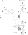
- Fig. 1 is a diagram illustrating an example of a hot water supply system according to each embodiment.
- a hot water supply system 1 includes a heat source machine 2, a hot water storage tank 3, a facility 4, an edge server 100B, and a cloud server 100C.
- the heat source machine 2 and the hot water storage tank 3 are connected to each other by a pipe 9B, and the hot water storage tank 3 and the facility 4 are connected to each other by a pipe 9C.
- Supplied water is supplied to the heat source machine 2 through a pipe 9A.
- the heat source machine 2 includes, for example, a refrigerant circuit including a compressor, a condenser, an expansion valve, and an evaporator, and exchanges heat using the condenser to heat supplied water and to generate hot water.
- a temperature sensor 5 that measures the temperature of the supplied water is provided on an inlet side of the heat source machine 2, and a temperature sensor 6 that measures the temperature of the heated hot water, that is, the temperature of the hot water to be supplied to the hot water storage tank 3 is provided on an outlet side of the heat source machine 2.
- a temperature sensor 6 that measures the temperature of the heated hot water, that is, the temperature of the hot water to be supplied to the hot water storage tank 3 is provided on an outlet side of the heat source machine 2.
- Fig. 1 only one heat source machine 2 is illustrated, but a plurality of heat source machines 2 may be provided.
- One or a plurality of heat source machines 2 send the generated hot water to the hot water storage tank 3 through the pipe 9B.
- the hot water storage tank 3 stores the sent hot water.
- a water level sensor 7 that measures a hot water storage amount is provided in the hot water storage tank 3.
- a controller 100A is provided in the heat source machine 2, and the controller 100A controls the heat source machine 2 such that the hot water storage amount measured by the water level sensor 7 becomes a target value. Then, the hot water in an amount corresponding to the demand of the facility 4 is supplied from the hot water storage tank 3 to the facility 4 through the pipe 9C.
- the hot water supply system 1 is provided with a sensor 8 that measures an outside air temperature.
- the controller 100A, the edge server 100B, and the cloud server 100C are computers including a processor.
- the controller 100A and the edge server 100B, and the edge server 100B and the cloud server 100C are connected to be able to communicate with each other.
- the cloud server 100C is a server that is provided outside a facility in which the heat source machine 2 and the hot water storage tank 3 are provided, for example, is present in a data center.
- the cloud server 100C performs the demand prediction of hot water, creation of a hot water storage plan in which the hot water storage amount of the hot water storage tank 3 is determined for each predetermined time, and the like. For example, a method of the demand prediction and a creation method of the hot water storage plan are disclosed in PTL 1.
- the edge server 100B is disposed in a facility in which the heat source machine 2 or the like is provided, and performs mediation between the controller 100A and the cloud server 100C, such as transmitting information (measured values of various sensors or the like) related to the heat source machine 2 and the hot water storage tank 3 to the cloud server 100C and receiving the hot water storage plan from the cloud server 100C.
- the pipe 9C is not provided with a flow rate sensor 99 that measures the amount of hot water to be supplied to the facility 4. Therefore, in the first embodiment, the measured values of the sensors 5 to 8 are acquired, and the flow rate of hot water to be supplied to the facility 4 through the pipe 9C is estimated. Then, the cloud server 100C performs the demand prediction of hot water on the basis of the estimated flow rate, and calculates a target value (hot water storage plan) of the hot water storage amount in accordance with the demand prediction. Then, the controller 100A operates the heat source machine 2 on the basis of the hot water storage plan. In a second embodiment and subsequent embodiments, the flow rate sensor 99 is illustrated by a broken line in Fig.
- the first embodiment relates to the method of measuring (estimating) the flow rate of hot water flowing through the pipe 9C in the same manner as the flow rate sensor 99 even without the flow rate sensor 99, but it is possible to apply the flow rate estimation method of the first embodiment even in a case where the flow rate sensor 99 is provided.
- Fig. 2 is a block diagram illustrating an example of the flow rate estimation device according to each embodiment.
- a flow rate estimation device 10 illustrated in the drawing is mounted on any of the controller 100A, the edge server 100B, and the cloud server 100C.
- Fig. 1 illustrates a configuration in which the cloud server 100C includes the flow rate estimation device 10.
- the flow rate estimation device 10 includes a data acquisition unit 11, a flow rate estimation unit 12, an output unit 13, and a storage unit 14.
- the data acquisition unit 11 acquires various kinds of information necessary for estimating the flow rate of hot water. For example, the data acquisition unit 11 acquires the measured values measured by the various sensors 5 to 8.
- the flow rate estimation unit 12 estimates the flow rate of hot water to be supplied to the facility 4 from the hot water storage tank 3 on the basis of the measured values or the like measured by the sensors 5 to 8.
- the output unit 13 outputs the flow rate estimated by the flow rate estimation unit 12 or transmits the flow rate to another device. For example, the output unit 13 outputs an estimated value of the flow rate of hot water to a hot water demand prediction unit (not illustrated) provided in the cloud server 100C.
- the storage unit 14 stores data and the like acquired by the data acquisition unit 11.
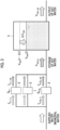
- Fig. 3 is a diagram illustrating the flow rate estimation method according to the first embodiment.
- Fig. 3 is a schematic view of a hot water supply system in which a plurality of (N H ) heat source machines 2 are provided.
- N H heat source machines 2
- an outflow rate of hot water from the hot water storage tank 3 can be calculated as a difference between the "amount of inflow into the tank” and the "change in the hot water storage amount".
- Outflow rate from hot water storage tank inflow rate to hot water storage tank - increase in hot water storage amount ...
- ⁇ Vtank Vtank t ⁇ Vtank t ⁇ ⁇ t
- V 1 F 1 / min ⁇ ⁇ t min
- T H, i, out is the temperature of hot water on the outlet side of the heat source machine 2 (measured value of the temperature sensor 6)
- T H, i, in is the temperature of the supplied water on the inlet side of the heat source machine 2 (measured value of the temperature sensor 5)
- Cp is the low-pressure specific heat of water (4.187 (kJ/kg•°C))
- G is the outflow rate of hot water flowing out from the heat source machine 2, that is, the inflow rate Vtank, in into the hot water storage tank 3 which is a problem.
- Q is a heating capacity of the heat source machine 2, and is a value determined from the temperature of the supplied water on the inlet side and the temperature of the hot water on the outlet side of the heat source machine 2 and the outside air temperature.
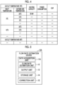
- a characteristic table related to the heating capacity illustrated in Fig. 4 is generally given.
- an inlet temperature (measured value of the temperature sensor 5), an outlet temperature (measured value of the temperature sensor 6), the outside air temperature (measured value of the temperature sensor 8), and the heating capacity Q are associated with each other.
- the value of the heating capacity Q is determined from the characteristic table of Fig.
- the flow rate estimation unit 12 estimates Vtank, out(1) by Expression (7) and Expression (1'), and estimates the flow rate (l/s) of hot water flowing through the pipe 9C by using Expression (3) from the estimated outflow rate (1).
- the output unit 13 outputs the flow rate estimated by the flow rate estimation unit 12.
- the present embodiment it is possible to estimate the flow rate of hot water to the facility 4 from the hot water storage tank 3 of the hot water supply system 1 in which the flow rate sensor 99 is not provided. As a result, it is possible to perform the demand prediction of hot water or create the hot water storage plan for the hot water supply system 1 in which the flow rate sensor 99 is not mounted. Since there is no need to install a flowmeter, it is possible to reduce the cost of installing the flowmeter, the labor and costs required for additions and maintenance, the labor required for repairs to flowmeter failures, and complaints.
- the flow rate can be estimated without depending on the system configuration (tank type, number of tanks, number of heat source machines, pipe length, pipe diameter, pipe height, and the like) of the customer side, and as described in the following embodiments, in the hot water supply system provided with the flow rate sensor 99, the system can also be used as a backup in the event of failure or deterioration of the flow rate sensor 99.
- a flow rate estimation device according to a second embodiment of the present disclosure will be described with reference to Figs. 5 to 8 .
- the flow rate sensor 99 is provided in Fig. 1 .
- Fig. 5 is a block diagram illustrating an example of the flow rate estimation device according to the second embodiment.
- a flow rate estimation device 10A includes a data acquisition unit 11A, the flow rate estimation unit 12, the output unit 13, the storage unit 14, and a correction unit 15.
- the data acquisition unit 11A acquires a measured value of the flow rate sensor 99 in addition to the sensors 5 to 8.
- the correction unit 15 corrects the estimated value of the outflow rate such that the estimated value approaches the actually measured value, on the basis of the relationship between the actually measured value and the estimated value of the outflow rate from the hot water storage tank 3.
- the vertical axis of is the estimated value (1/s) of the flow rate estimated by the flow rate estimation unit 12 using the method of the first embodiment
- the horizontal axis is the actually measured value (1/s) of the flow rate of hot water supplied from the hot water storage tank 3 to the facility 4 measured by the flow rate sensor 99.
- One point in the scatter graph of Fig. 6 illustrates a relationship between the estimated value and the actually measured value for the flow rate at a certain point in time.
- the data acquisition unit 11A acquires the measured value of the sensor 99 in addition to the sensors 5 to 8, and records the actually measured value of the flow rate of hot water in the storage unit 14 in association with the time point.
- the flow rate estimation unit 12 calculates the estimated value of the flow rate of hot water using the method described in the first embodiment on the basis of the measured values of the sensors 5 to 8, and records the estimated value in the storage unit 14 in association with the time point.
- the correction unit 15 creates a scatter graph illustrated in Fig. 6 on the basis of the estimated values and the actually measured values of the flow rate of hot water at the same time point recorded in the storage unit 14. In the case of the data illustrated in Fig. 6 , the estimated values are slightly greater values than the actually measured values.
- the correction unit 15 calculates a function of the estimated value and the actually measured value on the basis of the distribution of the scatter graph.
- f is a function representing a relationship between the actually measured value and the estimated value of the flow rate of hot water calculated by the correction unit 15.
- the correction unit 15 derives an inverse function f' of the function f, that is, a function f' for obtaining the actually measured value from the estimated value.
- the correction unit 15 substitutes the estimated value of the flow rate of hot water estimated by the flow rate estimation unit 12 into the inverse function f' derived in advance.
- Fig. 7 illustrates a relationship between the corrected estimated value and the actually measured value of the flow rate of hot water.
- the vertical axis illustrates the corrected estimated value
- the horizontal axis illustrates the actually measured value.
- Fig. 8 is a flowchart illustrating an example of the flow rate estimation processing according to the second embodiment.
- the flow rate estimation device 10A accumulates the estimated value and the actually measured value of the flow rate of hot water (step S1).
- the data acquisition unit 11A accumulates the measured value of the flow rate sensor 99 and the measurement time point in the storage unit 14, and the flow rate estimation unit 12 accumulates the estimated value of the flow rate and the estimation time point in the storage unit 14.
- the correction unit 15 derives a function for obtaining an actually measured value from the estimated value of the flow rate (step S2).
- the correction unit 15 may derive the function f for obtaining the estimated value from the actually measured value of the flow rate on the basis of the distribution shape of the scatter graph and then derive the inverse function f', or may derive the function corresponding to the inverse function f' from the beginning.
- the data acquisition unit 11A acquires the measured values of the sensors 5 to 8 (step S3), and stores the measured values in the storage unit 14.
- the flow rate estimation unit 12 estimates the flow rate of hot water supplied from the hot water storage tank 3 to the facility 4 by using the measured values stored in the storage unit 14, the characteristic table of Fig. 4 , and the above-described Expression (7), Expression (1'), and Expression (3) (step S4).
- the flow rate estimation unit 12 outputs the estimated flow rate to the correction unit 15.
- the correction unit 15 corrects the estimated value of the flow rate (step S5).
- the correction unit 15 substitutes the estimated value of the flow rate acquired from the flow rate estimation unit 12 into the function derived in step S2 to obtain the corrected estimated value of the flow rate.
- the output unit 13 outputs the flow rate corrected by the correction unit 15. Thereafter, the processing of step S3 and thereafter is repeatedly executed.
- the estimated value of the flow rate can be corrected on the basis of the actually measured value.
- the characteristic table illustrated in Fig. 4 is used, but the value of the characteristic table is a design value, and thus a difference occurs from the heating capacity Q in a case in which hot water is generated in an actual environment.
- the correction unit 15 By substituting the estimated value into the function of the actually measured value and the estimated value by the correction unit 15, it is possible to correct the error of the estimated value of the flow rate due to the difference.
- the function to be approximated is the quadratic function, but the function to be calculated by the correction unit 15 may not be the quadratic function.
- a flow rate estimation device 10B according to a third embodiment of the present disclosure will be described with reference to Figs. 9 to 12 .
- the flow rate sensor 99 is provided.
- the same correction as in the second embodiment is performed.
- Fig. 9 is a block diagram illustrating an example of the flow rate estimation device according to the third embodiment.
- the flow rate estimation device 10B includes a data acquisition unit 11B, the flow rate estimation unit 12, the output unit 13, the storage unit 14, a correction unit 15B, and a selection unit 16.
- the same configurations as those in the flow rate estimation device 10A will be denoted by the same reference numerals and the description thereof will be omitted.
- the data acquisition unit 11B acquires property information in addition to the measured values of the various sensors 5 to 8, and stores the property information in the storage unit 14.
- the property is a hot water supply system introduced in another facility.
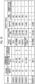
- Fig. 10 illustrates an example of the property information.
- the property information includes information such as the presence or absence of the flow rate sensor for each property, a specimen size of the actually measured value of the flow rate used to derive a correction expression, the correction expression (function used for the correction described in the second embodiment), and the property profile (the type of industry, the installation area, the type of tank, the volume of the tank, and the number of heat source machines).
- the hot water supply system 1 does not include the flow rate sensor 99, it is not possible to derive the function used for the correction by the method described in the second embodiment. Therefore, in the present embodiment, it is considered to select a property having a similar property profile from among properties provided with the flowmeter with reference to the property information illustrated in Fig. 10 , and to reuse the correction expression (function) of the selected property in the hot water supply system 1.
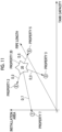
- the selection unit 16 selects a property having a similar property profile from among the properties provided with the flowmeter with reference to the property information acquired by the data acquisition unit 11. The processing of selecting the similar property by the selection unit 16 will be described with reference to Fig. 11 . For example, it is assumed that the hot water supply system 1 is a property 20 (bottom row) of the property information in Fig. 10 .
- the selection unit 16 selects, as a subset, for example, a representative similar property: B_similar from the viewpoints of the following (a) and/or (b).
- the correction unit 15B acquires the correction expression of the property selected by the selection unit 16 with reference to the property information acquired by the data acquisition unit 11, and corrects the estimated value of the flow rate estimation unit 12 by using the correction expression. For example, in a case where the selection unit 16 selects the properties 2, 3, and 5, the correction unit 15B substitutes the estimated value x of the flow rate estimation unit 12 into a correction expression f2 of the property 2 to calculate the corrected estimated value y2. Similarly, the correction unit 15B substitutes the estimated value x of the flow rate estimation unit 12 into a correction expression f3 of the property 3 and a correction expression f5 of the property 5, respectively to calculate the corrected estimation values y3 and y5.
- the correction unit 15B calculates an average value of y2, y3, and y5, and sets this average value as the corrected flow rate.
- the correction unit 15B may weight y2, y3, and y5 by the inverse number of the specimen size of the actually measured value of the flow rate and/or the distance D_i on the feature space ( Fig. 11 ) used for the derivation of the correction expression.
- An outline of the correction processing according to the present embodiment is illustrated in Fig. 12 . In Fig.
- N2, N3, and N5 are a specimen size of the property 2, a specimen size of the property 3, and a specimen size of the property 5, respectively, and D_2, D_3, and D_5 are a distance D_i between the property 20 and the property 2, a distance D_i between the property 20 and the property 3, and a distance D_i between the property 20 and the property 5, respectively.
- the corrected flow rate is calculated by the following expression, for example.
- the weight may be, for example, a logarithm of N2 or (1/D_2).
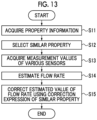
- Fig. 13 is a flowchart illustrating an example of the flow rate estimation processing according to the third embodiment.
- the data acquisition unit 11B acquires the property information (step S11).
- the data acquisition unit 11B stores the property information in the storage unit 14.
- the selection unit 16 selects a property similar to the hot water supply system 1 as an evaluation target with reference to the property information of the storage unit 14 (step S12).
- the selection unit 16 (a) selects a property having the same type of industry, or selects a similar property using, for example, a method of (b) comparing parameters that characterize the characteristics of the properties, such as the installation area, the pipe length, the tank capacity, the tank type, and the number of heat source machines and selecting properties similar to the property (hot water supply system 1) as the evaluation target.
- the selection unit 16 stores identification information of the selected property in the storage unit 14.
- the selection unit 16 stores the distance D_i calculated in the case of selecting the similar property, in the storage unit 14. This is the preparation stage.
- the data acquisition unit 11B acquires the measured values of the sensors 5 to 8 (step S13), and stores the measured values in the storage unit 14.
- the flow rate estimation unit 12 estimates the flow rate of hot water supplied from the hot water storage tank 3 to the facility 4 by using the measured values stored in the storage unit 14, the characteristic table of Fig. 4 , and the above-described Expression (7), Expression (1'), and Expression (3) (step S14).
- the flow rate estimation unit 12 outputs the estimated flow rate to the correction unit 15B.
- the correction unit 15B corrects the estimated value of the flow rate by using the correction expression of the similar property (step S15).
- the correction unit 15B acquires the correction expression of the property selected by the selection unit 16 with reference to the property information, and calculates an average or a weighted average of the values (in the example described above, y2, y3, and y5) obtained by correcting the flow rate using each correction expression.
- the weight for example, the inverse number of the specimen size Ni or the distance D_i
- the data acquisition unit 11B receives the setting and stores the setting in the storage unit 14.
- the correction unit 15B corrects the flow rate estimated by the flow rate estimation unit 12, for example, by (N2•y2 + N3•y3 + N5•y5) ⁇ (N2 + N3 + N5).
- the output unit 13 outputs the flow rate corrected by the correction unit 15B. Thereafter, the processing of step S13 and thereafter is repeatedly executed.
- the same correction as that of the second embodiment can be performed. Therefore, it is possible to improve the estimation accuracy of the flow rate, and to improve the accuracy of the demand prediction and the hot water storage plan.
- a flow rate estimation device according to a fourth embodiment of the present disclosure will be described with reference to Figs. 14 and 15 .
- the fourth embodiment can be combined with the first embodiment or the second embodiment.
- a configuration in a case where the fourth embodiment is combined with the second embodiment will be described as an example.
- the hot water supply system 1 includes the flow rate sensor 99.
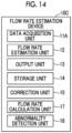
- Fig. 14 is a block diagram illustrating an example of the flow rate estimation device according to the fourth embodiment.
- a flow rate estimation device 10C includes the data acquisition unit 11A, the flow rate estimation unit 12, the output unit 13, the storage unit 14, the correction unit 15, a flow rate calculation unit 17, and an abnormality detection unit 18.
- the same configurations as those in the flow rate estimation device 10A will be denoted by the same reference numerals and the description thereof will be omitted.
- the data acquisition unit 11A acquires the measured value of the flow rate sensor 99 in addition to the measured values of the various sensors 5 to 8.
- the flow rate calculation unit 17 calculates the weighted average (including an arithmetic mean) of the corrected estimated values of the flow rate corrected by the correction unit 15 and the actually measured values of the flow rate acquired by the data acquisition unit 11A, as the flow rate of hot water.
- the average of the estimated values and the actually measured values is taken to stabilize the accuracy and improve the reliability.
- the flow rate calculation unit 17 calculates the weighted average of the estimated values of the flow rate estimated by the flow rate estimation unit 12 and the actually measured value of the flow rate acquired by the data acquisition unit 11A, as the flow rate of hot water.
- the abnormality detection unit 18 detects the abnormality of the flow rate sensor 99 on the basis of the difference between the estimated value of the flow rate of hot water estimated by the flow rate estimation unit 12 or the corrected estimated value of the flow rate corrected by the correction unit 15 and the actually measured value of the flow rate measured by the flow rate sensor 99.
- the abnormality detection unit 18 continuously monitors the difference between the (corrected) estimated value and the actually measured value, or in a case where the difference is equal to or greater than the threshold value, or in a case where the state continues for a predetermined time or more or the difference between is equal to or greater than the threshold value a predetermined number of times or more within a predetermined time, the abnormality detection unit 18 determines that an abnormality such as a failure or deterioration occurs in the flow rate sensor 99, and outputs an alert.
- the flow rate calculation unit 17 may calculate the flow rate by setting the weighting for the estimated value to be greater than before. This is because it is considered that the estimated value has higher accuracy and reliability in a case where the abnormality of the flow rate sensor 99 occurs.
- Fig. 15 is a flowchart illustrating an example of the flow rate estimation processing according to the fourth embodiment.
- the flow rate estimation device 10C repeatedly executes the following processing.
- the data acquisition unit 11A acquires the measured values of the various sensors (step S21).
- the data acquisition unit 11A acquires the measured values of the sensors 5 to 8 and 99, and stores the measured values in the storage unit 14.
- the flow rate estimation unit 12 estimates the flow rate by the processing described in the first embodiment
- the correction unit 15 corrects the estimated value of the flow rate by the processing described in the second embodiment (step S22). In the case of a configuration in which the correction unit 15 is not provided (in a case where the fourth embodiment is combined with the first embodiment), only the estimation of the flow rate is executed.
- the flow rate calculation unit 17 calculates the weighted average of the actually measured value of the flow rate acquired in step S21 and the estimated value or corrected estimated value of the flow rate calculated in step S22 (step S23).
- the output unit 13 outputs the calculated value as the flow rate of hot water.
- the abnormality detection unit 18 calculates the difference between the actually measured value of the flow rate acquired in step S21 and the estimated value or the corrected estimated value of the flow rate calculated in step S22, and determines whether or not the difference is equal to or greater than the threshold value (step S24). In a case where the difference is less than the threshold value (step S24; No), the processing flow of Fig. 15 ends, and the processing from step S21 is repeatedly executed again.
- the abnormality detection unit 18 issues an alert for notifying that the abnormality of the flow rate sensor 99 is detected (step S25).
- the flow rate calculation unit 17 sets the weighting for the estimated value or the corrected estimated value to be greater than before (step S26). For example, in a situation where the abnormality of the flow rate sensor 99 is not detected, weighting may be performed equally on the estimated value and the actually measured value, and after the abnormality of the flow rate sensor 99 is detected, the weighting for the estimated value or the corrected estimated value may be set to be larger at a ratio of 7:3, for example. Alternatively, the weighting after the abnormality is detected may be set by the user, and appropriate weighting may be performed in accordance with the degree of abnormality of the flow rate sensor 99.
- the determination in step S24 may be that a state where the difference between the actually measured value and the (corrected) estimated value is equal to or larger than the threshold value continues for a predetermined time or more, or that the difference between the actually measured value and the (corrected) estimated value is equal to or greater than the threshold value a predetermined number of times or more within a predetermined time.
- the reliability of the calculated flow rate can be improved by calculating the flow rate using both the estimated value and actually measured value of the flow rate.
- the accuracy of the calculated flow rate value can be maintained by giving a greater weight on the estimated value and calculating the flow rate.
- the flow rate sensor 99 fails and needs to be replaced or repaired, the hot water supply system 1 cannot be operated until the repair is completed in general, but the flow rate can be estimated by the flow rate estimation unit 12, so that the operation of the hot water supply system 1 can be continued.
- Fig. 16 is a diagram illustrating an example of a hardware configuration of the flow rate estimation device according to each embodiment.
- a computer 900 includes a CPU 901, a main storage device 902, an auxiliary storage device 903, an input and output interface 904, and a communication interface 905.
- the flow rate estimation devices 10 to 10C described above are mounted on the computer 900. Then, each of the functions described above is stored in the auxiliary storage device 903 in the form of a program.
- the CPU 901 reads out the program from the auxiliary storage device 903, expands the program in the main storage device 902, and executes the above-described processing according to the program.
- the CPU 901 allocates a storage area in the main storage device 902 according to the program.
- the CPU 901 allocates a storage area for storing data being processed, in the auxiliary storage device 903 according to the program.
- a program for realizing all or a part of the functions of the flow rate estimation devices 10 to 10C is recorded on a computer-readable recording medium, and the program recorded on the recording medium is read into a computer system and executed, whereby processing by each functional unit may be performed.
- the "computer system” herein includes an OS and hardware such as peripheral devices.
- the “computer system” also includes a homepage providing environment (or display environment) in a case where a WWW system is used.
- the "computer-readable recording medium” refers to a portable medium such as a CD, a DVD, or a USB, or a storage device such as a hard disk built into the computer system.
- the computer 900 to which the program is distributed may expand the program in the main storage device 902 and execute the processing described above.
- the program described above may be for realizing a part of the above functions, or may further realize the above-described functions in combination with a program already recorded in the computer system.
- the flow rate estimation device, the flow rate estimation method, and the program described in each embodiment are understood as follows, for example.
- the flow rate estimation device According to the flow rate estimation device, the flow rate estimation method, and the program described above, it is possible to estimate the flow rate of hot water supplied from the hot water supply system to the load.
Landscapes
- Engineering & Computer Science (AREA)
- Physics & Mathematics (AREA)
- Thermal Sciences (AREA)
- Chemical & Material Sciences (AREA)
- Combustion & Propulsion (AREA)
- Mechanical Engineering (AREA)
- General Engineering & Computer Science (AREA)
- Computer Hardware Design (AREA)
- Fluid Mechanics (AREA)
- General Physics & Mathematics (AREA)
- Automation & Control Theory (AREA)
- Heat-Pump Type And Storage Water Heaters (AREA)
Abstract
Description
- The present disclosure relates to a flow rate estimation device, a flow rate estimation method, and a program. The present disclosure claims priority based on
Japanese Patent Application No. 2022-131090, filed in Japan on August 19, 2022 - A hot water supply system is used to supply hot water to kitchens and bath facilities of restaurants, hotels, schools, hospitals, welfare facilities, and the like. In the hot water supply system, a water heater heats supplied water and stores the heated hot water in a hot water storage tank. Then, the hot water stored in the hot water storage tank is supplied to the kitchens, bath facilities, and the like. For efficient operation of the hot water supply system, a method of creating a hot water storage plan that can predict future demand for hot water and avoid hot water outage while satisfying daily demand prediction has been proposed (for example, PTL 1). In order to create such a hot water storage plan, it is essential to accurately predict the demand for hot water. For example, in a case where a sensor that measures the flow rate of hot water supplied from a hot water storage tank to a facility on the demand side is provided in the hot water supply system, the demand prediction can be performed by recording the daily flow rate measured by the sensor and learning the recorded data.
- [PTL 1]
Japanese Unexamined Patent Application Publication No. 2021-181852 - As described above, there is a hot water supply system in which a sensor that measures the amount of hot water supplied from the hot water storage tank is not provided. In such a hot water supply system, it is not possible to perform demand prediction on the basis of the amount of hot water measured by the sensor. A method of estimating the amount of hot water supplied from the hot water supply system in which the sensor for measuring the amount of hot water is not provided, to the facility is required.
- The present disclosure provides a flow rate estimation device, a flow rate estimation method, and a program capable of solving the problems described above. Solution to Problem
- A flow rate estimation device according to an aspect of the present disclosure is a flow rate estimation device that estimates a flow rate of hot water supplied from a hot water supply system including a heat source machine and a hot water storage tank that stores hot water created by the heat source machine, the flow rate estimation device including a flow rate estimation unit configured to estimate an inflow rate of hot water to the hot water storage tank, from a first temperature that is a temperature of water flowing into the heat source machine, a second temperature that is a temperature of hot water supplied from the heat source machine to the hot water storage tank, and a heating capacity of the heat source machine calculated on a basis of the first temperature, the second temperature, and an outside air temperature, and to estimate a flow rate of hot water supplied from the hot water storage tank, from the inflow rate and a change in a hot water storage amount of the hot water storage tank.
- A flow rate estimation method according to another aspect of the present disclosure is a flow rate estimation method of estimating a flow rate of hot water supplied from a hot water supply system including a heat source machine and a hot water storage tank that stores hot water created by the heat source machine, the flow rate estimation method including estimating an inflow rate of hot water to the hot water storage tank, from a first temperature that is a temperature of water flowing into the heat source machine, a second temperature that is a temperature of hot water supplied from the heat source machine to the hot water storage tank, and a heating capacity of the heat source machine calculated on a basis of the first temperature, the second temperature, and an outside air temperature, and estimating a flow rate of hot water supplied from the hot water storage tank, from the inflow rate and a change in a hot water storage amount of the hot water storage tank.
- A program according to another aspect of the present disclosure is a program for causing a computer to execute processing of estimating a flow rate of hot water supplied from a hot water supply system including a heat source machine and a hot water storage tank that stores hot water created by the heat source machine, the processing including estimating an inflow rate of hot water to the hot water storage tank, from a first temperature that is a temperature of water flowing into the heat source machine, a second temperature that is a temperature of hot water supplied from the heat source machine to the hot water storage tank, and a heating capacity of the heat source machine calculated on a basis of the first temperature, the second temperature, and an outside air temperature, and estimating a flow rate of hot water supplied from the hot water storage tank, from the inflow rate and a change in a hot water storage amount of the hot water storage tank.
- According to the flow rate estimation device, the flow rate estimation method, and the program described above, it is possible to estimate the flow rate of hot water supplied from the hot water supply system to the load.
-
-
Fig. 1 is a diagram illustrating an example of a hot water supply system according to each embodiment. -
Fig. 2 is a block diagram illustrating an example of a flow rate estimation device according to a first embodiment. -
Fig. 3 is a diagram illustrating a flow rate estimation method according to the first embodiment. -
Fig. 4 is a diagram illustrating an example of a characteristic table of a heat source machine according to the first embodiment. -
Fig. 5 is a block diagram illustrating an example of a flow rate estimation device according to a second embodiment. -
Fig. 6 is a diagram illustrating correction processing of a flow rate according to the second embodiment. -
Fig. 7 is a diagram illustrating an example of a relationship between a corrected flow rate estimated value and an actually measured value according to the second embodiment. -
Fig. 8 is a flowchart illustrating an example of flow rate estimation processing according to the second embodiment. -
Fig. 9 is a block diagram illustrating an example of a flow rate estimation device according to a third embodiment. -
Fig. 10 is a diagram illustrating an example of property information according to the third embodiment. -
Fig. 11 is a diagram illustrating a selection method of similar properties according to the third embodiment. -
Fig. 12 is a diagram illustrating correction processing according to the third embodiment. -
Fig. 13 is a flowchart illustrating an example of flow rate estimation processing according to the third embodiment. -
Fig. 14 is a block diagram illustrating an example of a flow rate estimation device according to a fourth embodiment. -
Fig. 15 is a flowchart illustrating an example of flow rate estimation processing according to the fourth embodiment. -
Fig. 16 is a diagram illustrating an example of a hardware configuration of the flow rate estimation device according to each embodiment. - Hereinafter, a flow rate estimation method of the present disclosure will be described with reference to the drawings.
-
Fig. 1 is a diagram illustrating an example of a hot water supply system according to each embodiment. - As illustrated in the figure, a hot
water supply system 1 includes aheat source machine 2, a hotwater storage tank 3, afacility 4, anedge server 100B, and acloud server 100C. Theheat source machine 2 and the hotwater storage tank 3 are connected to each other by apipe 9B, and the hotwater storage tank 3 and thefacility 4 are connected to each other by apipe 9C. Supplied water is supplied to theheat source machine 2 through apipe 9A. Theheat source machine 2 includes, for example, a refrigerant circuit including a compressor, a condenser, an expansion valve, and an evaporator, and exchanges heat using the condenser to heat supplied water and to generate hot water. Atemperature sensor 5 that measures the temperature of the supplied water is provided on an inlet side of theheat source machine 2, and atemperature sensor 6 that measures the temperature of the heated hot water, that is, the temperature of the hot water to be supplied to the hotwater storage tank 3 is provided on an outlet side of theheat source machine 2. InFig. 1 , only oneheat source machine 2 is illustrated, but a plurality ofheat source machines 2 may be provided. One or a plurality ofheat source machines 2 send the generated hot water to the hotwater storage tank 3 through thepipe 9B. The hotwater storage tank 3 stores the sent hot water. Awater level sensor 7 that measures a hot water storage amount is provided in the hotwater storage tank 3. Acontroller 100A is provided in theheat source machine 2, and thecontroller 100A controls theheat source machine 2 such that the hot water storage amount measured by thewater level sensor 7 becomes a target value. Then, the hot water in an amount corresponding to the demand of thefacility 4 is supplied from the hotwater storage tank 3 to thefacility 4 through thepipe 9C. The hotwater supply system 1 is provided with asensor 8 that measures an outside air temperature. - The
controller 100A, theedge server 100B, and thecloud server 100C are computers including a processor. Thecontroller 100A and theedge server 100B, and theedge server 100B and thecloud server 100C are connected to be able to communicate with each other. Thecloud server 100C is a server that is provided outside a facility in which theheat source machine 2 and the hotwater storage tank 3 are provided, for example, is present in a data center. Thecloud server 100C performs the demand prediction of hot water, creation of a hot water storage plan in which the hot water storage amount of the hotwater storage tank 3 is determined for each predetermined time, and the like. For example, a method of the demand prediction and a creation method of the hot water storage plan are disclosed inPTL 1. Theedge server 100B is disposed in a facility in which theheat source machine 2 or the like is provided, and performs mediation between thecontroller 100A and thecloud server 100C, such as transmitting information (measured values of various sensors or the like) related to theheat source machine 2 and the hotwater storage tank 3 to thecloud server 100C and receiving the hot water storage plan from thecloud server 100C. - Here, the
pipe 9C is not provided with aflow rate sensor 99 that measures the amount of hot water to be supplied to thefacility 4. Therefore, in the first embodiment, the measured values of thesensors 5 to 8 are acquired, and the flow rate of hot water to be supplied to thefacility 4 through thepipe 9C is estimated. Then, thecloud server 100C performs the demand prediction of hot water on the basis of the estimated flow rate, and calculates a target value (hot water storage plan) of the hot water storage amount in accordance with the demand prediction. Then, thecontroller 100A operates theheat source machine 2 on the basis of the hot water storage plan. In a second embodiment and subsequent embodiments, theflow rate sensor 99 is illustrated by a broken line inFig. 1 in order to describe an application example in a case where theflow rate sensor 99 is provided. The first embodiment relates to the method of measuring (estimating) the flow rate of hot water flowing through thepipe 9C in the same manner as theflow rate sensor 99 even without theflow rate sensor 99, but it is possible to apply the flow rate estimation method of the first embodiment even in a case where theflow rate sensor 99 is provided. - Next, a flow rate estimation device that estimates the flow rate of hot water will be described with reference to
Fig. 2 . -
Fig. 2 is a block diagram illustrating an example of the flow rate estimation device according to each embodiment. - A flow
rate estimation device 10 illustrated in the drawing is mounted on any of thecontroller 100A, theedge server 100B, and thecloud server 100C. As an example,Fig. 1 illustrates a configuration in which thecloud server 100C includes the flowrate estimation device 10. As illustrated inFig. 2 , the flowrate estimation device 10 includes adata acquisition unit 11, a flowrate estimation unit 12, anoutput unit 13, and astorage unit 14. - The
data acquisition unit 11 acquires various kinds of information necessary for estimating the flow rate of hot water. For example, thedata acquisition unit 11 acquires the measured values measured by thevarious sensors 5 to 8. - The flow
rate estimation unit 12 estimates the flow rate of hot water to be supplied to thefacility 4 from the hotwater storage tank 3 on the basis of the measured values or the like measured by thesensors 5 to 8. - The
output unit 13 outputs the flow rate estimated by the flowrate estimation unit 12 or transmits the flow rate to another device. For example, theoutput unit 13 outputs an estimated value of the flow rate of hot water to a hot water demand prediction unit (not illustrated) provided in thecloud server 100C. - The
storage unit 14 stores data and the like acquired by thedata acquisition unit 11. - Next, the method of estimating the flow rate of hot water supplied to be supplied to the
facility 4 from the hotwater storage tank 3 by the flowrate estimation unit 12 will be described with reference toFigs. 3 and4 .Fig. 3 is a diagram illustrating the flow rate estimation method according to the first embodiment.Fig. 3 is a schematic view of a hot water supply system in which a plurality of (NH)heat source machines 2 are provided. As in Expression (1), an outflow rate of hot water from the hotwater storage tank 3 can be calculated as a difference between the "amount of inflow into the tank" and the "change in the hot water storage amount".Outflow rate from hot water storage tank = inflow rate to hot water storage tank - increase in hot water storage amount ... - The change in hot water storage amount of the second term on the right side of Expression (1) can be measured by the
water level sensor 7. Then, the problem is how to estimate the inflow rate into the hotwater storage tank 3. Here, in a case where the outflow rate is represented by Vtank, out(1), the inflow rate is represented by Vtank, in(1), and a change in the hot water storage amount is represented by ΔVtank(1), Expression (1) can be represented as follows.
- Here, ΔVtank is a change in the hot water storage amount in the infinitesimal time Δt as illustrated in Expression (2).

- The relationship between the volume V(1) and the flow rate F(1/min) that represent the outflow rate and the inflow rate can be represented as follows.

- As thermodynamic formulae related to the hot
water supply system 1, the following Expressions (4) and (5) are known to be established.

- Here, TH, i, out is the temperature of hot water on the outlet side of the heat source machine 2 (measured value of the temperature sensor 6), TH, i, in is the temperature of the supplied water on the inlet side of the heat source machine 2 (measured value of the temperature sensor 5), Cp is the low-pressure specific heat of water (4.187 (kJ/kg•°C)), and G is the outflow rate of hot water flowing out from the
heat source machine 2, that is, the inflow rate Vtank, in into the hotwater storage tank 3 which is a problem. Q is a heating capacity of theheat source machine 2, and is a value determined from the temperature of the supplied water on the inlet side and the temperature of the hot water on the outlet side of theheat source machine 2 and the outside air temperature. Specifically, as specification data of theheat source machine 2, a characteristic table related to the heating capacity illustrated inFig. 4 is generally given. In the characteristic table, an inlet temperature (measured value of the temperature sensor 5), an outlet temperature (measured value of the temperature sensor 6), the outside air temperature (measured value of the temperature sensor 8), and the heating capacity Q are associated with each other. The value of the heating capacity Q is determined from the characteristic table ofFig. 4 and the measured values of thetemperature sensors temperature sensors water storage tank 3 can be further calculated from Expression (1'). - It is assumed that the outflow rate from the i-th
heat source machine 2 among the NHheat source machines 2 is represented by GH, i, the heating capacity of the i-thheat source machine 2 is represented by QH, i, the temperature of the supplied water on the inlet side is represented by TH, i, in, and the temperature of the supplied water on the outlet side is represented by TH, i, out. In a case where Expression (4) is modified, the following Expression (6) is obtained.
- Therefore, the inflow rate Vtank, in into the hot
water storage tank 3 in the unit time Δt can be obtained by Expression (7).
[Equation 1]
- The flow
rate estimation unit 12 estimates Vtank, out(1) by Expression (7) and Expression (1'), and estimates the flow rate (l/s) of hot water flowing through thepipe 9C by using Expression (3) from the estimated outflow rate (1). Theoutput unit 13 outputs the flow rate estimated by the flowrate estimation unit 12. - As described above, according to the present embodiment, it is possible to estimate the flow rate of hot water to the
facility 4 from the hotwater storage tank 3 of the hotwater supply system 1 in which theflow rate sensor 99 is not provided. As a result, it is possible to perform the demand prediction of hot water or create the hot water storage plan for the hotwater supply system 1 in which theflow rate sensor 99 is not mounted. Since there is no need to install a flowmeter, it is possible to reduce the cost of installing the flowmeter, the labor and costs required for additions and maintenance, the labor required for repairs to flowmeter failures, and complaints. The flow rate can be estimated without depending on the system configuration (tank type, number of tanks, number of heat source machines, pipe length, pipe diameter, pipe height, and the like) of the customer side, and as described in the following embodiments, in the hot water supply system provided with theflow rate sensor 99, the system can also be used as a backup in the event of failure or deterioration of theflow rate sensor 99. - Hereinafter, a flow rate estimation device according to a second embodiment of the present disclosure will be described with reference to
Figs. 5 to 8 . In the hot water supply system according to the second embodiment, theflow rate sensor 99 is provided inFig. 1 . -
Fig. 5 is a block diagram illustrating an example of the flow rate estimation device according to the second embodiment. - Among the configurations according to the second embodiment, the same configurations as those in the flow
rate estimation device 10 according to the first embodiment will be denoted by the same reference numerals and the description thereof will be omitted. A flowrate estimation device 10A includes adata acquisition unit 11A, the flowrate estimation unit 12, theoutput unit 13, thestorage unit 14, and acorrection unit 15. - The
data acquisition unit 11A acquires a measured value of theflow rate sensor 99 in addition to thesensors 5 to 8. - The
correction unit 15 corrects the estimated value of the outflow rate such that the estimated value approaches the actually measured value, on the basis of the relationship between the actually measured value and the estimated value of the outflow rate from the hotwater storage tank 3. - Next, correction processing of the flow rate according to the second embodiment will be described with reference to
Fig. 6 . - In the scatter graph of
Fig. 6 , the vertical axis of is the estimated value (1/s) of the flow rate estimated by the flowrate estimation unit 12 using the method of the first embodiment, and the horizontal axis is the actually measured value (1/s) of the flow rate of hot water supplied from the hotwater storage tank 3 to thefacility 4 measured by theflow rate sensor 99. One point in the scatter graph ofFig. 6 illustrates a relationship between the estimated value and the actually measured value for the flow rate at a certain point in time. Thedata acquisition unit 11A acquires the measured value of thesensor 99 in addition to thesensors 5 to 8, and records the actually measured value of the flow rate of hot water in thestorage unit 14 in association with the time point. The flowrate estimation unit 12 calculates the estimated value of the flow rate of hot water using the method described in the first embodiment on the basis of the measured values of thesensors 5 to 8, and records the estimated value in thestorage unit 14 in association with the time point. Thecorrection unit 15 creates a scatter graph illustrated inFig. 6 on the basis of the estimated values and the actually measured values of the flow rate of hot water at the same time point recorded in thestorage unit 14. In the case of the data illustrated inFig. 6 , the estimated values are slightly greater values than the actually measured values. Thecorrection unit 15 calculates a function of the estimated value and the actually measured value on the basis of the distribution of the scatter graph. Here, in a case where the estimated value is y and the actually measured value is x, thecorrection unit 15 approximates the relationship between the estimated value and the actually measured value by, for example, a quadratic function y = ax2 + bx + c. InFig. 6 , f is a function representing a relationship between the actually measured value and the estimated value of the flow rate of hot water calculated by thecorrection unit 15. Thecorrection unit 15 derives an inverse function f' of the function f, that is, a function f' for obtaining the actually measured value from the estimated value. Next, thecorrection unit 15 substitutes the estimated value of the flow rate of hot water estimated by the flowrate estimation unit 12 into the inverse function f' derived in advance. Then, the corrected estimated value of the flow rate of hot water is obtained.Fig. 7 illustrates a relationship between the corrected estimated value and the actually measured value of the flow rate of hot water. In the scatter graph ofFig. 7 , the vertical axis illustrates the corrected estimated value, and the horizontal axis illustrates the actually measured value. As illustrated inFig. 7 , the corrected estimated values of the flow rate and the actually measured values are distributed substantially on the line of y = x. That is, by the correction by thecorrection unit 15, it is possible to estimate the flow rate closer to the actually measured value. -
Fig. 8 is a flowchart illustrating an example of the flow rate estimation processing according to the second embodiment. - The flow
rate estimation device 10A accumulates the estimated value and the actually measured value of the flow rate of hot water (step S1). Thedata acquisition unit 11A accumulates the measured value of theflow rate sensor 99 and the measurement time point in thestorage unit 14, and the flowrate estimation unit 12 accumulates the estimated value of the flow rate and the estimation time point in thestorage unit 14. Next, thecorrection unit 15 derives a function for obtaining an actually measured value from the estimated value of the flow rate (step S2). As described usingFig. 6 , thecorrection unit 15 may derive the function f for obtaining the estimated value from the actually measured value of the flow rate on the basis of the distribution shape of the scatter graph and then derive the inverse function f', or may derive the function corresponding to the inverse function f' from the beginning. Thecorrection unit 15 stores the derived function or the coefficients of the function (in a case where the inverse function f' is y = a'x2 + b'x + c', the coefficients are a', b', and c') in thestorage unit 14. This is the preparation stage. - Next, the flow rate estimation processing during the operation will be described. First, the
data acquisition unit 11A acquires the measured values of thesensors 5 to 8 (step S3), and stores the measured values in thestorage unit 14. Next, the flowrate estimation unit 12 estimates the flow rate of hot water supplied from the hotwater storage tank 3 to thefacility 4 by using the measured values stored in thestorage unit 14, the characteristic table ofFig. 4 , and the above-described Expression (7), Expression (1'), and Expression (3) (step S4). The flowrate estimation unit 12 outputs the estimated flow rate to thecorrection unit 15. Next, thecorrection unit 15 corrects the estimated value of the flow rate (step S5). Thecorrection unit 15 substitutes the estimated value of the flow rate acquired from the flowrate estimation unit 12 into the function derived in step S2 to obtain the corrected estimated value of the flow rate. Theoutput unit 13 outputs the flow rate corrected by thecorrection unit 15. Thereafter, the processing of step S3 and thereafter is repeatedly executed. - According to the present embodiment, the estimated value of the flow rate can be corrected on the basis of the actually measured value. For example, in the estimation method of the flow rate described in the first embodiment, the characteristic table illustrated in
Fig. 4 is used, but the value of the characteristic table is a design value, and thus a difference occurs from the heating capacity Q in a case in which hot water is generated in an actual environment. By substituting the estimated value into the function of the actually measured value and the estimated value by thecorrection unit 15, it is possible to correct the error of the estimated value of the flow rate due to the difference. In the above description, the function to be approximated is the quadratic function, but the function to be calculated by thecorrection unit 15 may not be the quadratic function. - Hereinafter, a flow
rate estimation device 10B according to a third embodiment of the present disclosure will be described with reference toFigs. 9 to 12 . In the second embodiment, it is assumed that theflow rate sensor 99 is provided. However, in the third embodiment, even in the case of the hotwater supply system 1 in which theflow rate sensor 99 is not provided, the same correction as in the second embodiment is performed. -
Fig. 9 is a block diagram illustrating an example of the flow rate estimation device according to the third embodiment. - The flow
rate estimation device 10B according to the third embodiment includes adata acquisition unit 11B, the flowrate estimation unit 12, theoutput unit 13, thestorage unit 14, acorrection unit 15B, and aselection unit 16. Among the configurations of the flowrate estimation device 10B, the same configurations as those in the flowrate estimation device 10A will be denoted by the same reference numerals and the description thereof will be omitted. - The
data acquisition unit 11B acquires property information in addition to the measured values of thevarious sensors 5 to 8, and stores the property information in thestorage unit 14. The property is a hot water supply system introduced in another facility.Fig. 10 illustrates an example of the property information. The property information includes information such as the presence or absence of the flow rate sensor for each property, a specimen size of the actually measured value of the flow rate used to derive a correction expression, the correction expression (function used for the correction described in the second embodiment), and the property profile (the type of industry, the installation area, the type of tank, the volume of the tank, and the number of heat source machines). Since the hotwater supply system 1 according to the present embodiment does not include theflow rate sensor 99, it is not possible to derive the function used for the correction by the method described in the second embodiment. Therefore, in the present embodiment, it is considered to select a property having a similar property profile from among properties provided with the flowmeter with reference to the property information illustrated inFig. 10 , and to reuse the correction expression (function) of the selected property in the hotwater supply system 1. - The
selection unit 16 selects a property having a similar property profile from among the properties provided with the flowmeter with reference to the property information acquired by thedata acquisition unit 11. The processing of selecting the similar property by theselection unit 16 will be described with reference toFig. 11 . For example, it is assumed that the hotwater supply system 1 is a property 20 (bottom row) of the property information inFig. 10 . - (Procedure 1) The set of properties having the flow rate sensor is denoted by B_observable. Assume that the following conditions are satisfied. B_observable = {
property 2,property 3,property 5,property 7,property 11, property 16} (properties - (Procedure 2) Among these, the
selection unit 16 selects, as a subset, for example, a representative similar property: B_similar from the viewpoints of the following (a) and/or (b). - (a) A set of properties having the same type of industry is selected. In the case of the example in
Fig. 10 , B_similar = {property 2, property 11}. - (b) Other property profiles (installation area, tank type, tank volume, pipe length, and the like) of the property (property 20) are compared at a distance D_i (i is a property number) on a feature space, and k properties having a high degree of similarity are selected.
Fig. 11 illustrates a diagram in which three parameters of the property profile, that is, the location, the tank capacity, and the pipe length are taken on each coordinate axis of a three-dimensional coordinate space as an example, and each property is plotted in the coordinate space. As illustrated in the drawing, theproperties property 20, theproperty 3 is positioned at a slightly separated position, and theproperty 7 is positioned at a separated position. Theselection unit 16 calculates the distance D_i between the properties, and selects k properties in order from the property having the shortest distance. InFig. 11 , in a case where k = 3, B_similar = {property 2,property 3, and property 5}. InFig. 11 , only three parameters are used for convenience of illustration, but theselection unit 16 may calculate the distance D_i between the properties in a case where the properties are plotted in a multi-dimensional space by using all the parameters (five types of parameters in the example ofFig. 10 ) of the property profiles. Theselection unit 16 may select the property (in this case, the property 2) selected from both the viewpoints (a) and (b), or may select all the properties selected by any of the viewpoints (a) and (b). Alternatively, theselection unit 16 may select the property only from the viewpoint of one of (a) or (b). - The
correction unit 15B acquires the correction expression of the property selected by theselection unit 16 with reference to the property information acquired by thedata acquisition unit 11, and corrects the estimated value of the flowrate estimation unit 12 by using the correction expression. For example, in a case where theselection unit 16 selects theproperties correction unit 15B substitutes the estimated value x of the flowrate estimation unit 12 into a correction expression f2 of theproperty 2 to calculate the corrected estimated value y2. Similarly, thecorrection unit 15B substitutes the estimated value x of the flowrate estimation unit 12 into a correction expression f3 of theproperty 3 and a correction expression f5 of theproperty 5, respectively to calculate the corrected estimation values y3 and y5. Then, thecorrection unit 15B calculates an average value of y2, y3, and y5, and sets this average value as the corrected flow rate. Thecorrection unit 15B may weight y2, y3, and y5 by the inverse number of the specimen size of the actually measured value of the flow rate and/or the distance D_i on the feature space (Fig. 11 ) used for the derivation of the correction expression. An outline of the correction processing according to the present embodiment is illustrated inFig. 12 . InFig. 12 , N2, N3, and N5 are a specimen size of theproperty 2, a specimen size of theproperty 3, and a specimen size of theproperty 5, respectively, and D_2, D_3, and D_5 are a distance D_i between theproperty 20 and theproperty 2, a distance D_i between theproperty 20 and theproperty 3, and a distance D_i between theproperty 20 and theproperty 5, respectively. In a case where weighting is performed by both the inverse number of the specimen size Ni and the distance Di, the corrected flow rate is calculated by the following expression, for example.Corrected flow rate = {N2 × (1/D_2) × y2 + N3 × (1/D_3) × y3 + N5 × (1/D_5) × y5} ÷ {N2 × (1/D_2) + N3 × (1/D_3) + N5 × (1/D_5)} - The weight may be, for example, a logarithm of N2 or (1/D_2).
-
Fig. 13 is a flowchart illustrating an example of the flow rate estimation processing according to the third embodiment. - The
data acquisition unit 11B acquires the property information (step S11). Thedata acquisition unit 11B stores the property information in thestorage unit 14. Next, theselection unit 16 selects a property similar to the hotwater supply system 1 as an evaluation target with reference to the property information of the storage unit 14 (step S12). For example, with reference to the property profile, the selection unit 16 (a) selects a property having the same type of industry, or selects a similar property using, for example, a method of (b) comparing parameters that characterize the characteristics of the properties, such as the installation area, the pipe length, the tank capacity, the tank type, and the number of heat source machines and selecting properties similar to the property (hot water supply system 1) as the evaluation target. Theselection unit 16 stores identification information of the selected property in thestorage unit 14. Theselection unit 16 stores the distance D_i calculated in the case of selecting the similar property, in thestorage unit 14. This is the preparation stage. - Next, the flow rate estimation processing during the operation will be described. First, the
data acquisition unit 11B acquires the measured values of thesensors 5 to 8 (step S13), and stores the measured values in thestorage unit 14. Next, the flowrate estimation unit 12 estimates the flow rate of hot water supplied from the hotwater storage tank 3 to thefacility 4 by using the measured values stored in thestorage unit 14, the characteristic table ofFig. 4 , and the above-described Expression (7), Expression (1'), and Expression (3) (step S14). The flowrate estimation unit 12 outputs the estimated flow rate to thecorrection unit 15B. Next, thecorrection unit 15B corrects the estimated value of the flow rate by using the correction expression of the similar property (step S15). Thecorrection unit 15B acquires the correction expression of the property selected by theselection unit 16 with reference to the property information, and calculates an average or a weighted average of the values (in the example described above, y2, y3, and y5) obtained by correcting the flow rate using each correction expression. In a case of performing the correction using the weighted average, the weight (for example, the inverse number of the specimen size Ni or the distance D_i) to be given may be set by a user. For example, in a case where the user sets to perform weighting using the specimen size Ni as the weight, thedata acquisition unit 11B receives the setting and stores the setting in thestorage unit 14. In a case where weighting using the specimen size Ni is set in thestorage unit 14, thecorrection unit 15B corrects the flow rate estimated by the flowrate estimation unit 12, for example, by (N2•y2 + N3•y3 + N5•y5) ÷ (N2 + N3 + N5). Theoutput unit 13 outputs the flow rate corrected by thecorrection unit 15B. Thereafter, the processing of step S13 and thereafter is repeatedly executed. - According to the present embodiment, even in the hot
water supply system 1 in which theflow rate sensor 99 is not provided, the same correction as that of the second embodiment can be performed. Therefore, it is possible to improve the estimation accuracy of the flow rate, and to improve the accuracy of the demand prediction and the hot water storage plan. - Hereinafter, a flow rate estimation device according to a fourth embodiment of the present disclosure will be described with reference to
Figs. 14 and15 . The fourth embodiment can be combined with the first embodiment or the second embodiment. However, here, a configuration in a case where the fourth embodiment is combined with the second embodiment will be described as an example. In the fourth embodiment, it is assumed that the hotwater supply system 1 includes theflow rate sensor 99. -
Fig. 14 is a block diagram illustrating an example of the flow rate estimation device according to the fourth embodiment. - A flow
rate estimation device 10C according to the fourth embodiment includes thedata acquisition unit 11A, the flowrate estimation unit 12, theoutput unit 13, thestorage unit 14, thecorrection unit 15, a flowrate calculation unit 17, and anabnormality detection unit 18. Among the configurations of the flowrate estimation device 10C, the same configurations as those in the flowrate estimation device 10A will be denoted by the same reference numerals and the description thereof will be omitted. - The
data acquisition unit 11A acquires the measured value of theflow rate sensor 99 in addition to the measured values of thevarious sensors 5 to 8. - The flow
rate calculation unit 17 calculates the weighted average (including an arithmetic mean) of the corrected estimated values of the flow rate corrected by thecorrection unit 15 and the actually measured values of the flow rate acquired by thedata acquisition unit 11A, as the flow rate of hot water. In theflow rate sensor 99, there is a possibility that the accuracy of the measured value may be decreased due to deterioration, failure, noise, and the like. Therefore, in the fourth embodiment, the average of the estimated values and the actually measured values is taken to stabilize the accuracy and improve the reliability. In a case where the fourth embodiment is combined with the first embodiment, the flowrate calculation unit 17 calculates the weighted average of the estimated values of the flow rate estimated by the flowrate estimation unit 12 and the actually measured value of the flow rate acquired by thedata acquisition unit 11A, as the flow rate of hot water. - The
abnormality detection unit 18 detects the abnormality of theflow rate sensor 99 on the basis of the difference between the estimated value of the flow rate of hot water estimated by the flowrate estimation unit 12 or the corrected estimated value of the flow rate corrected by thecorrection unit 15 and the actually measured value of the flow rate measured by theflow rate sensor 99. For example, theabnormality detection unit 18 continuously monitors the difference between the (corrected) estimated value and the actually measured value, or in a case where the difference is equal to or greater than the threshold value, or in a case where the state continues for a predetermined time or more or the difference between is equal to or greater than the threshold value a predetermined number of times or more within a predetermined time, theabnormality detection unit 18 determines that an abnormality such as a failure or deterioration occurs in theflow rate sensor 99, and outputs an alert. In a case where theabnormality detection unit 18 detects the abnormality of theflow rate sensor 99, the flowrate calculation unit 17 may calculate the flow rate by setting the weighting for the estimated value to be greater than before. This is because it is considered that the estimated value has higher accuracy and reliability in a case where the abnormality of theflow rate sensor 99 occurs. -
Fig. 15 is a flowchart illustrating an example of the flow rate estimation processing according to the fourth embodiment. - The flow
rate estimation device 10C repeatedly executes the following processing. - The
data acquisition unit 11A acquires the measured values of the various sensors (step S21). Thedata acquisition unit 11A acquires the measured values of thesensors 5 to 8 and 99, and stores the measured values in thestorage unit 14. Next, the flowrate estimation unit 12 estimates the flow rate by the processing described in the first embodiment, and thecorrection unit 15 corrects the estimated value of the flow rate by the processing described in the second embodiment (step S22). In the case of a configuration in which thecorrection unit 15 is not provided (in a case where the fourth embodiment is combined with the first embodiment), only the estimation of the flow rate is executed. Next, the flowrate calculation unit 17 calculates the weighted average of the actually measured value of the flow rate acquired in step S21 and the estimated value or corrected estimated value of the flow rate calculated in step S22 (step S23). Theoutput unit 13 outputs the calculated value as the flow rate of hot water. - Next, the
abnormality detection unit 18 calculates the difference between the actually measured value of the flow rate acquired in step S21 and the estimated value or the corrected estimated value of the flow rate calculated in step S22, and determines whether or not the difference is equal to or greater than the threshold value (step S24). In a case where the difference is less than the threshold value (step S24; No), the processing flow ofFig. 15 ends, and the processing from step S21 is repeatedly executed again. - In a case where the difference is equal to or greater than the threshold value (step S24; Yes), the
abnormality detection unit 18 issues an alert for notifying that the abnormality of theflow rate sensor 99 is detected (step S25). In a case where the alert is issued, the flowrate calculation unit 17 sets the weighting for the estimated value or the corrected estimated value to be greater than before (step S26). For example, in a situation where the abnormality of theflow rate sensor 99 is not detected, weighting may be performed equally on the estimated value and the actually measured value, and after the abnormality of theflow rate sensor 99 is detected, the weighting for the estimated value or the corrected estimated value may be set to be larger at a ratio of 7:3, for example. Alternatively, the weighting after the abnormality is detected may be set by the user, and appropriate weighting may be performed in accordance with the degree of abnormality of theflow rate sensor 99. - The determination in step S24 may be that a state where the difference between the actually measured value and the (corrected) estimated value is equal to or larger than the threshold value continues for a predetermined time or more, or that the difference between the actually measured value and the (corrected) estimated value is equal to or greater than the threshold value a predetermined number of times or more within a predetermined time.
- According to the present embodiment, the reliability of the calculated flow rate can be improved by calculating the flow rate using both the estimated value and actually measured value of the flow rate. By comparing the estimated value and the actually measured value of the flow rate with each other, it is possible to detect the abnormality of the
flow rate sensor 99, and after the abnormality is detected, the accuracy of the calculated flow rate value can be maintained by giving a greater weight on the estimated value and calculating the flow rate. In a case where theflow rate sensor 99 fails and needs to be replaced or repaired, the hotwater supply system 1 cannot be operated until the repair is completed in general, but the flow rate can be estimated by the flowrate estimation unit 12, so that the operation of the hotwater supply system 1 can be continued. -
Fig. 16 is a diagram illustrating an example of a hardware configuration of the flow rate estimation device according to each embodiment. - A
computer 900 includes aCPU 901, amain storage device 902, anauxiliary storage device 903, an input andoutput interface 904, and acommunication interface 905. - The flow
rate estimation devices 10 to 10C described above are mounted on thecomputer 900. Then, each of the functions described above is stored in theauxiliary storage device 903 in the form of a program. TheCPU 901 reads out the program from theauxiliary storage device 903, expands the program in themain storage device 902, and executes the above-described processing according to the program. TheCPU 901 allocates a storage area in themain storage device 902 according to the program. TheCPU 901 allocates a storage area for storing data being processed, in theauxiliary storage device 903 according to the program. - A program for realizing all or a part of the functions of the flow
rate estimation devices 10 to 10C is recorded on a computer-readable recording medium, and the program recorded on the recording medium is read into a computer system and executed, whereby processing by each functional unit may be performed. The "computer system" herein includes an OS and hardware such as peripheral devices. The "computer system" also includes a homepage providing environment (or display environment) in a case where a WWW system is used. The "computer-readable recording medium" refers to a portable medium such as a CD, a DVD, or a USB, or a storage device such as a hard disk built into the computer system. In a case where the program is distributed to thecomputer 900 by a communication line, thecomputer 900 to which the program is distributed may expand the program in themain storage device 902 and execute the processing described above. The program described above may be for realizing a part of the above functions, or may further realize the above-described functions in combination with a program already recorded in the computer system. - While certain embodiments according to the present disclosure have been described, these embodiments have been presented by way of example only, and are not intended to limit the scope of the inventions. These embodiments can be implemented in various other forms, and various omissions, replacements, and changes can be made without departing from the gist of the invention. These embodiments and modifications thereof are included in the scope of the invention described in the claims and the equivalent scope thereof, as well as in the scope and gist of the invention.
- The flow rate estimation device, the flow rate estimation method, and the program described in each embodiment are understood as follows, for example.
- (1) A flow rate estimation device according to a first aspect is a flow rate estimation device that estimates a flow rate of hot water supplied from a hot water supply system including a heat source machine and a hot water storage tank that stores hot water created by the heat source machine, the flow rate estimation device including: a flow rate estimation unit configured to estimate an inflow rate of hot water to the hot water storage tank, from a first temperature that is a temperature of water flowing into the heat source machine, a second temperature that is a temperature of hot water supplied from the heat source machine to the hot water storage tank, and a heating capacity of the heat source machine calculated on a basis of the first temperature, the second temperature, and an outside air temperature, and to estimate a flow rate of hot water supplied from the hot water storage tank, from the inflow rate and a change in a hot water storage amount of the hot water storage tank.
Accordingly, the flow rate can be measured (estimated) even in a case where a flowmeter that measures the flow rate of hot water supplied from the hot water storage tank is not provided. - (2) A flow rate estimation device according to a second aspect is the flow rate estimation device of (1), and further includes: a correction unit configured to derive a function for obtaining an actually measured value of the flow rate of hot water, from the estimated value of the flow rate of hot water estimated by the flow rate estimation unit, and to correct the estimated value of the flow rate of hot water estimated by the flow rate estimation unit, on a basis of the function.
As a result, the accuracy of the estimated value of the flow rate can be improved. - (3) A flow rate estimation device according to a third aspect is the flow rate estimation device of (2), and further includes: a selection unit configured to select, from among property information including the function calculated for other hot water supply systems other than the hot water supply system as an evaluation target and characteristic information of the other hot water supply systems, the other hot water supply systems having similar characteristic information to the hot water supply system as the evaluation target, wherein the correction unit corrects the estimated value of the flow rate of hot water in the hot water supply system as the evaluation target, on the basis of the function derived for the other hot water supply systems selected by the selection unit, the estimated value being estimated by the flow rate estimation unit.
Accordingly, even in the case of the hot water supply system in which the flow rate sensor is not provided, the correction of the estimated value of the flow rate can be performed by using the function of correcting the estimated value of the flow rate derived in the other hot water supply systems. - (4) A flow rate estimation device according to a fourth aspect is the flow rate estimation device of (3), in which the selection unit calculates a degree of similarity between the characteristic information of the other hot water supply systems and characteristic information of the hot water supply system as the evaluation target, and the correction unit corrects the estimated value of the flow rate of hot water estimated by the flow rate estimation unit by performing weighting in accordance with the degree of similarity on the function selected by the selection unit.
As a result, the correction of the estimated value can be performed by performing weighting with a greater weight by the function derived from the other hot water supply systems having a high degree of similarity. - (5) A flow rate estimation device according to a fifth aspect is the flow rate estimation device of (3) and (4), in which the correction unit corrects the estimated value of the flow rate of hot water estimated by the flow rate estimation unit by performing weighting in accordance with numbers of the estimated value of the flow rate and the actually measured value of the flow rate that are used for deriving the function included in the property information.
As a result, the correction of the estimated value can be performed by giving a greater weight to the function having a large number of samples (specimen size) of the actually measured value and a high degree of reliability. - (6) A flow rate estimation device according to a sixth aspect is the flow rate estimation device of (1) to (5), and further includes: a flow rate calculation unit configured to calculate a weighted average of the estimated value of the flow rate of hot water estimated by the flow rate estimation unit and an actually measured value of the flow rate of hot water, as the flow rate of hot water.
By calculating the flow rate on the basis of the estimated value and the actually measured value, it is possible to expect improvement and stabilization of accuracy. - (7) A flow rate estimation device according to a seventh aspect is the flow rate estimation device of (2) to (5), and further includes: a flow rate calculation unit configured to calculate a weighted average of the corrected estimated value of the flow rate of hot water corrected by the correction unit and the actually measured value of the flow rate of hot water, as the flow rate of hot water.
By calculating the flow rate on the basis of the corrected estimated value and the actually measured value, it is possible to expect improvement and stabilization of accuracy. - (8) A flow rate estimation device according to an eighth aspect is the flow rate estimation device of (1) to (7), and further includes: an abnormality detection unit configured to detect an abnormality of a sensor that measures an actually measured value of the flow rate of hot water, on a basis of a difference between the estimated value of the flow rate of hot water estimated by the flow rate estimation unit and the actually measured value.
Accordingly, it is possible to detect an abnormality of the flow rate sensor. - (9) A flow rate estimation device according to a ninth aspect is the flow rate estimation device of (1) to (7), and further includes: a flow rate calculation unit configured to calculate a weighted average of the estimated value of the flow rate of hot water estimated by the flow rate estimation unit and an actually measured value of the flow rate of hot water, as the flow rate of hot water; and an abnormality detection unit configured to detect an abnormality of a sensor that measures the actually measured value, on a basis of a difference between the estimated value and the actually measured value, wherein in a case where the abnormality detection unit detects an abnormality, the flow rate calculation unit sets weighting to the estimated value to be greater than before.
Accordingly, in a case where an abnormality of the flow rate sensor is detected, it is possible to calculate the flow rate by giving a larger weight on the estimated value. - (10) A flow rate estimation method according to a tenth aspect is a flow rate estimation method of estimating a flow rate of hot water supplied from a hot water supply system including a heat source machine and a hot water storage tank that stores hot water created by the heat source machine, the flow rate estimation method including: estimating an inflow rate of hot water to the hot water storage tank, from a first temperature that is a temperature of water flowing into the heat source machine, a second temperature that is a temperature of hot water supplied from the heat source machine to the hot water storage tank, and a heating capacity of the heat source machine calculated on a basis of the first temperature, the second temperature, and an outside air temperature, and estimating a flow rate of hot water supplied from the hot water storage tank, from the inflow rate and a change in a hot water storage amount of the hot water storage tank.
- (11) A program according to an eleventh aspect is a program for causing a
computer 900 to execute processing of estimating a flow rate of hot water supplied from a hot water supply system including a heat source machine and a hot water storage tank that stores hot water created by the heat source machine, the processing including: estimating an inflow rate of hot water to the hot water storage tank, from a first temperature that is a temperature of water flowing into the heat source machine, a second temperature that is a temperature of hot water supplied from the heat source machine to the hot water storage tank, and a heating capacity of the heat source machine calculated on a basis of the first temperature, the second temperature, and an outside air temperature, and estimating a flow rate of hot water supplied from the hot water storage tank, from the inflow rate and a change in a hot water storage amount of the hot water storage tank. - According to the flow rate estimation device, the flow rate estimation method, and the program described above, it is possible to estimate the flow rate of hot water supplied from the hot water supply system to the load.
-
- 1: hot water supply system
- 2: heat source machine
- 3: hot water storage tank
- 4: facility
- 5, 6, 8: temperature sensor
- 7: water level sensor
- 99: flow rate sensor
- 100A: controller
- 100B: edge server
- 100C: cloud server
- 10: flow rate estimation device
- 11: data acquisition unit
- 12: flow rate estimation unit
- 13: output unit
- 14: storage unit
- 15: correction unit
- 900: computer
- 901: CPU
- 902: main storage device
- 903: auxiliary storage device
- 904: input and output interface
- 905: communication interface
Claims (11)
- A flow rate estimation device that estimates a flow rate of hot water supplied from a hot water supply system including a heat source machine and a hot water storage tank that stores hot water created by the heat source machine, the flow rate estimation device comprising:
a flow rate estimation unit configured to estimate an inflow rate of hot water to the hot water storage tank, from a first temperature that is a temperature of water flowing into the heat source machine, a second temperature that is a temperature of hot water supplied from the heat source machine to the hot water storage tank, and a heating capacity of the heat source machine calculated on a basis of the first temperature, the second temperature, and an outside air temperature, and to estimate a flow rate of hot water supplied from the hot water storage tank, from the inflow rate and a change in a hot water storage amount of the hot water storage tank. - The flow rate estimation device according to claim 1, further comprising:
a correction unit configured to derive a function for obtaining an actually measured value of the flow rate of hot water, from the estimated value of the flow rate of hot water estimated by the flow rate estimation unit, and to correct the estimated value of the flow rate of hot water estimated by the flow rate estimation unit, on a basis of the function. - The flow rate estimation device according to claim 2, further comprising:a selection unit configured to select, from among property information including the function calculated for other hot water supply systems other than the hot water supply system as an evaluation target and characteristic information of the other hot water supply systems, the other hot water supply systems having similar characteristic information to the hot water supply system as the evaluation target,wherein the correction unit corrects the estimated value of the flow rate of hot water in the hot water supply system as the evaluation target, on the basis of the function derived for the other hot water supply systems selected by the selection unit, the estimated value being estimated by the flow rate estimation unit.
- The flow rate estimation device according to claim 3,wherein the selection unit calculates a degree of similarity between the characteristic information of the other hot water supply systems and characteristic information of the hot water supply system as the evaluation target, andthe correction unit corrects the estimated value of the flow rate of hot water estimated by the flow rate estimation unit by performing weighting in accordance with the degree of similarity on the function selected by the selection unit.
- The flow rate estimation device according to claim 3 or 4,
wherein the correction unit corrects the estimated value of the flow rate of hot water estimated by the flow rate estimation unit by performing weighting in accordance with numbers of the estimated value of the flow rate and the actually measured value of the flow rate that are used for deriving the function included in the property information. - The flow rate estimation device according to claim 1, further comprising:
a flow rate calculation unit configured to calculate a weighted average of the estimated value of the flow rate of hot water estimated by the flow rate estimation unit and an actually measured value of the flow rate of hot water, as the flow rate of hot water. - The flow rate estimation device according to claim 2, further comprising:
a flow rate calculation unit configured to calculate a weighted average of the corrected estimated value of the flow rate of hot water corrected by the correction unit and the actually measured value of the flow rate of hot water, as the flow rate of hot water. - The flow rate estimation device according to claim 1 or 2, further comprising:
an abnormality detection unit configured to detect an abnormality of a sensor that measures an actually measured value of the flow rate of hot water, on a basis of a difference between the estimated value of the flow rate of hot water estimated by the flow rate estimation unit and the actually measured value. - The flow rate estimation device according to claim 1 or 2, further comprising:a flow rate calculation unit configured to calculate a weighted average of the estimated value of the flow rate of hot water estimated by the flow rate estimation unit and an actually measured value of the flow rate of hot water, as the flow rate of hot water; andan abnormality detection unit configured to detect an abnormality of a sensor that measures the actually measured value, on a basis of a difference between the estimated value and the actually measured value,wherein in a case where the abnormality detection unit detects an abnormality, the flow rate calculation unit sets weighting to the estimated value to be greater than before.
- A flow rate estimation method of estimating a flow rate of hot water supplied from a hot water supply system including a heat source machine and a hot water storage tank that stores hot water created by the heat source machine, the flow rate estimation method comprising:
estimating an inflow rate of hot water to the hot water storage tank, from a first temperature that is a temperature of water flowing into the heat source machine, a second temperature that is a temperature of hot water supplied from the heat source machine to the hot water storage tank, and a heating capacity of the heat source machine calculated on a basis of the first temperature, the second temperature, and an outside air temperature, and estimating a flow rate of hot water supplied from the hot water storage tank, from the inflow rate and a change in a hot water storage amount of the hot water storage tank. - A program for causing a computer to execute processing of estimating a flow rate of hot water supplied from a hot water supply system including a heat source machine and a hot water storage tank that stores hot water created by the heat source machine, the processing comprising:
estimating an inflow rate of hot water to the hot water storage tank, from a first temperature that is a temperature of water flowing into the heat source machine, a second temperature that is a temperature of hot water supplied from the heat source machine to the hot water storage tank, and a heating capacity of the heat source machine calculated on a basis of the first temperature, the second temperature, and an outside air temperature, and estimating a flow rate of hot water supplied from the hot water storage tank, from the inflow rate and a change in a hot water storage amount of the hot water storage tank.
Applications Claiming Priority (2)
| Application Number | Priority Date | Filing Date | Title |
|---|---|---|---|
| JP2022131090A JP2024027909A (en) | 2022-08-19 | 2022-08-19 | Flow rate estimation device, flow rate estimation method and program |
| PCT/JP2023/029458 WO2024038851A1 (en) | 2022-08-19 | 2023-08-14 | Flow rate estimation device, flow rate estimation method, and program |
Publications (2)
| Publication Number | Publication Date |
|---|---|
| EP4567346A1 true EP4567346A1 (en) | 2025-06-11 |
| EP4567346A4 EP4567346A4 (en) | 2025-10-22 |
Family
ID=89941710
Family Applications (1)
| Application Number | Title | Priority Date | Filing Date |
|---|---|---|---|
| EP23854885.3A Pending EP4567346A4 (en) | 2022-08-19 | 2023-08-14 | FLOW RATE ESTIMATION DEVICE, FLOW RATE ESTIMATION METHOD AND PROGRAM |
Country Status (3)
| Country | Link |
|---|---|
| EP (1) | EP4567346A4 (en) |
| JP (1) | JP2024027909A (en) |
| WO (1) | WO2024038851A1 (en) |
Family Cites Families (8)
| Publication number | Priority date | Publication date | Assignee | Title |
|---|---|---|---|---|
| JPH0387562A (en) * | 1989-08-29 | 1991-04-12 | Kyocera Corp | Storage type hot-water supply apparatus |
| JP3001961B2 (en) * | 1990-11-09 | 2000-01-24 | 株式会社ガスター | Flow rate detection method, flow rate control method, and flow rate detection device for reheating circuit |
| CN103562645A (en) * | 2011-06-03 | 2014-02-05 | 瑞姆澳大利亚控股有限公司 | A water heater controller or system |
| JP6191531B2 (en) * | 2014-04-17 | 2017-09-06 | 三菱電機株式会社 | Hot water storage water heater |
| US10302312B2 (en) * | 2014-12-22 | 2019-05-28 | Battelle Memorial Institute | Estimation of unknown states for an electric water heater with thermal stratification and use of same in demand response and condition-based maintenance |
| JP2020165608A (en) * | 2019-03-29 | 2020-10-08 | 三菱重工サーマルシステムズ株式会社 | Outflow amount estimation device, demand amount prediction device, control device, inflow amount estimation device, inflow amount estimation model creation device, outflow amount estimation method and program |
| JP7531308B2 (en) | 2020-05-19 | 2024-08-09 | 三菱重工サーマルシステムズ株式会社 | Hot water storage plan creation system, hot water storage plan creation method and program |
| JP7572049B2 (en) | 2021-02-26 | 2024-10-23 | 国立研究開発法人物質・材料研究機構 | Composition, member, and protective equipment |
-
2022
- 2022-08-19 JP JP2022131090A patent/JP2024027909A/en active Pending
-
2023
- 2023-08-14 WO PCT/JP2023/029458 patent/WO2024038851A1/en not_active Ceased
- 2023-08-14 EP EP23854885.3A patent/EP4567346A4/en active Pending
Also Published As
| Publication number | Publication date |
|---|---|
| JP2024027909A (en) | 2024-03-01 |
| WO2024038851A1 (en) | 2024-02-22 |
| EP4567346A4 (en) | 2025-10-22 |
Similar Documents
| Publication | Publication Date | Title |
|---|---|---|
| AU2022250941B2 (en) | Air conditioning system, abnormality estimation method for air conditioning system, air conditioner and abnormality estimation method for air conditioner | |
| Yoon et al. | Hidden factors and handling strategies on virtual in-situ sensor calibration in building energy systems: Prior information and cancellation effect | |
| JP6856443B2 (en) | Equipment abnormality diagnosis system | |
| JP5525965B2 (en) | Refrigeration cycle equipment | |
| US12411479B2 (en) | Method and apparatus for determining cause of abnormality in a semiconductor manufacturing chamber | |
| EP3431893B1 (en) | Air-conditioner blowout temperature estimation device and program | |
| WO2016163163A1 (en) | Threshold value calculation system, and threshold value calculation method | |
| JP2016177676A (en) | Diagnostic device, diagnostic method, diagnostic system, and diagnostic program | |
| JP7466788B2 (en) | Equipment maintenance support device and its operation method | |
| CN105659176A (en) | Detection of faults when determining concentrations of chemical components in a distillation column | |
| Sun et al. | Online sensor fault diagnosis for robust chiller sequencing control | |
| EP4490393B1 (en) | Operational optimization of industrial steam and power utility systems | |
| US12578065B2 (en) | Management system and management method, and computer-readable storage medium | |
| CN110462538A (en) | Information processing apparatus, information processing method, and program | |
| JP5350684B2 (en) | Failure diagnosis device used for refrigeration cycle equipment | |
| Huang et al. | Fusion of redundant measurements for enhancing the reliability of total cooling load based chiller sequencing control | |
| WO2024038851A1 (en) | Flow rate estimation device, flow rate estimation method, and program | |
| JP6559598B2 (en) | Plant evaluation apparatus and plant evaluation method | |
| CN113557397A (en) | Refrigerant amount estimation device, method and program | |
| JP6245653B2 (en) | Liquid leakage detection device, liquid leakage detection method, and recording medium | |
| KR20220119939A (en) | Apparatus and method for estimating main feed water flow rate | |
| JP2010025474A (en) | Failure diagnostic device used in refrigerating cycle equipment | |
| JP7292674B2 (en) | State estimation device, state estimation program, state estimation method | |
| JP2026037851A (en) | Flow rate estimation device, flow rate estimation method and program | |
| US12072094B2 (en) | Intelligent prediction of boiler blowdown |
Legal Events
| Date | Code | Title | Description |
|---|---|---|---|
| STAA | Information on the status of an ep patent application or granted ep patent |
Free format text: STATUS: THE INTERNATIONAL PUBLICATION HAS BEEN MADE |
|
| PUAI | Public reference made under article 153(3) epc to a published international application that has entered the european phase |
Free format text: ORIGINAL CODE: 0009012 |
|
| STAA | Information on the status of an ep patent application or granted ep patent |
Free format text: STATUS: REQUEST FOR EXAMINATION WAS MADE |
|
| 17P | Request for examination filed |
Effective date: 20250305 |
|
| AK | Designated contracting states |
Kind code of ref document: A1 Designated state(s): AL AT BE BG CH CY CZ DE DK EE ES FI FR GB GR HR HU IE IS IT LI LT LU LV MC ME MK MT NL NO PL PT RO RS SE SI SK SM TR |
|
| A4 | Supplementary search report drawn up and despatched |
Effective date: 20250919 |
|
| RIC1 | Information provided on ipc code assigned before grant |
Ipc: F24H 15/148 20220101AFI20250915BHEP Ipc: F24H 1/18 20220101ALI20250915BHEP Ipc: F24H 15/215 20220101ALI20250915BHEP Ipc: F24H 15/219 20220101ALI20250915BHEP Ipc: F24H 15/258 20220101ALI20250915BHEP Ipc: G05D 23/19 20060101ALI20250915BHEP |
|
| DAV | Request for validation of the european patent (deleted) | ||
| DAX | Request for extension of the european patent (deleted) |