EP4566893A1 - Work vehicle - Google Patents
Work vehicle Download PDFInfo
- Publication number
- EP4566893A1 EP4566893A1 EP23849677.2A EP23849677A EP4566893A1 EP 4566893 A1 EP4566893 A1 EP 4566893A1 EP 23849677 A EP23849677 A EP 23849677A EP 4566893 A1 EP4566893 A1 EP 4566893A1
- Authority
- EP
- European Patent Office
- Prior art keywords
- opening
- lid member
- recessed portion
- work vehicle
- battery
- Prior art date
- Legal status (The legal status is an assumption and is not a legal conclusion. Google has not performed a legal analysis and makes no representation as to the accuracy of the status listed.)
- Pending
Links
Images



Classifications
-
- B—PERFORMING OPERATIONS; TRANSPORTING
- B60—VEHICLES IN GENERAL
- B60R—VEHICLES, VEHICLE FITTINGS, OR VEHICLE PARTS, NOT OTHERWISE PROVIDED FOR
- B60R16/00—Electric or fluid circuits specially adapted for vehicles and not otherwise provided for; Arrangement of elements of electric or fluid circuits specially adapted for vehicles and not otherwise provided for
- B60R16/02—Electric or fluid circuits specially adapted for vehicles and not otherwise provided for; Arrangement of elements of electric or fluid circuits specially adapted for vehicles and not otherwise provided for electric constitutive elements
- B60R16/04—Arrangement of batteries
Definitions
- the present invention relates to a work vehicle.
- Patent Document 1 there is a work vehicle (electric tractor) that includes an electric motor that drives a travel device, a battery room formed by an openable and closable cover member (hood), and a battery that is provided in the battery room and supplies power to the electric motor.
- a work vehicle electric tractor
- hood openable and closable cover member
- Patent Document 1 JP 2022-60665A
- the above-described work vehicle includes a service plug configured to shut off a power source circuit that uses the battery as a power source.
- a service plug configured to shut off a power source circuit that uses the battery as a power source.
- the power source circuit will be shut off and the travel device will not be able to be driven.
- the present invention provides a work vehicle including a service plug that is not likely to be operated by mistake and is not likely to be soiled by mud and the like.
- a work vehicle includes: an electric motor configured to drive a travel device; a battery room formed by an openable and closable cover member; a battery provided in the battery room and configured to supply power to the electric motor; and a service plug configured to shut off a power source circuit that uses the battery as a power source, in which a recessed portion and a lid member configured to open and close the recessed portion are provided on an upper surface portion of the battery, and the service plug is accommodated in the recessed portion and is covered from above by the lid member.
- the service plug is in the recessed portion of the battery and is covered and hidden by the lid member. Therefore, the service plug can be made less likely to be operated by mistake. Since mud and the like that is splashed up by the travel device is not likely to reach the upper surface portion of the battery where the recess is, the service plug can be made less likely to be soiled by mud and the like.
- the cover member is supported in such a manner as to be swingable up and down to be opened and closed using, as a swing support point, an opening and closing axis that is at an end portion on a body rearward side of the cover member and extends along a body lateral direction, and the end portion on the body rearward side of the opening of the recessed portion is below the opening and closing axis.
- an interval between the cover member and the opening when the cover member is opened is narrower than in a case where the opening is on a body frontward side relative to the opening and closing axis. That is, even if the cover member is opened, the interval between the cover member and the lid member is narrow, and therefore the service plug can be made less likely to be operated by mistake.
- the opening is non-circular, and a peripheral edge of the opening includes a first peripheral edge portion that corresponds to the end portion on the body rearward side of the opening and extends in the body lateral direction along the opening and closing axis, and the peripheral edge of the opening includes a second peripheral edge portion that corresponds to an end portion on a body frontward side of the opening and extends in the body lateral direction parallel to the first peripheral edge portion.
- the opening compared to a case where the opening is circular, the opening can be made wider while preventing the interval between the cover member and the opening from becoming too wide when the cover member is opened. Therefore, it is easier to operate the service plug when it is necessary to shut off the power source circuit.
- the opening has an octagonal shape.
- the area of the part of the opening on the body frontward side relative to the opening and closing axis can be made larger, and therefore it is easier to operate the service plug.
- both sides of the opening include screw members configured to fasten the lid member to the upper surface portion, and the screw members are provided on a body front side relative to the opening and closing axis.
- the screw members can be operated at a location on the body front side relative to the opening and closing axis, that is, at a location where the cover member is unlikely to interfere with operation, and therefore it is easier to operate the screw members.
- a power source fuse is provided adjacent to the service plug.
- the fuse is on the body front side relative to the service plug.
- the upper surface portion is provided with a second recessed portion separate from the recessed portion, and a second lid member that is configured to open and close the second recessed portion and is separate from the lid member, and the fuse is accommodated in the second recessed portion and is covered from above by the second lid member.
- the fuse when the service plug is operated, the fuse can be kept covered by the second lid member and the fuse can be prevented from being touched.
- a hexalobular screw configured to fasten the second lid member to the upper surface portion.
- the fuse can be made less likely to be operated by mistake.
- FIGS. 1 and 2 An electric tractor is shown in FIGS. 1 and 2 .
- This electric tractor is included in various types of working machines, such as a riding tiller formed by coupling a rotary tilling device (not shown) to the body rear portion, or a riding grass cutter formed by coupling a grass cutting device (not shown) to the body lower portion.
- the front-rear direction of the travel body of the electric tractor is defined along the body forward travel direction when in the working state, and the left-right direction of the travel body is defined as viewed in the forward travel direction of the travel body. That is, the direction indicated by the symbol (F) in FIGS. 1 , 2 , and the like is a body front side, and the direction indicated by the symbol (B) in FIGS. 1 , 2 , and the like is a body rear side.
- the direction indicated by the symbol (L) in FIG. 2 and the like is a body left side, and the direction indicated by the symbol (R) in FIG. 2 and the like is a body right side. Accordingly, the body left-right direction corresponds to a body lateral direction.
- the direction indicated by the symbol (U) in FIG. 1 and the like is a body upper side
- the direction indicated by the symbol (D) in FIG. 1 and the like is a body lower side.
- the electric tractor includes a travel body 3 supported by steerable and drivable front wheels 1 serving as a pair of left and right travel devices, and drivable rear wheels 2 serving as a pair of left and right travel devices.
- a motor section 5 including an electric motor 4 for driving the front wheels 1 and the rear wheels 2 is provided at a front portion of the travel body 3.
- a driving section 6 in which an operator sits is provided at a rear portion of the travel body 3.
- the driving section 6 includes a driver's seat 7, a steering wheel 8 for steering the front wheels 1, and a ROPS 9 serving as a driver protection device.
- a body frame 10 includes, for example, a front frame 11a that supports the front wheels 1 and the like, and a transmission case 11 whose front portion is coupled to the rear portion of the front frame 11a and that supports the rear wheels 2 and the like.
- the motor section 5 includes a battery room 13 formed by a cover member 12.
- the battery room 13 is provided with a battery 14.
- the electric motor 4 that drives the front wheels 1 and the rear wheels 2 and an inverter 15 that converts DC power from the battery 14 into AC power and supplies the AC power to the electric motor 4 are provided below the battery 14.
- the electric motor 4 and the inverter 15 are arranged in the body front-rear direction with the electric motor 4 on the body rearward side relative to the inverter 15.
- the electric motor 4 is supported by the front frame 11a.
- the output of the electric motor 4 is input to a hydrostatic continuously variable transmission 17 (see FIG. 1 ) provided at a front portion of the transmission case 11 via a rotary shaft 16 (see FIG. 1 ) extending from the electric motor 4 toward the body rear side, and is then input from the continuously variable transmission 17 to the transmission case 11.
- the input power is transmitted to a driving transmission (not shown) and then transmitted from the driving transmission to the rear wheels 2 and the front wheels 1. Power is transmitted from the driving transmission to the front wheels 1 via a rotary shaft 18 extending from the transmission case 11 toward the body front.
- the battery 14 is placed on a battery placement platform 19 (see FIG. 1 ) supported by the front frame 11a.
- the battery 14 is provided with a service plug 20 (see FIGS. 3 and 5 ) and two fuses 21 (see FIGS. 3 and 5 ) by which a power source circuit that uses the battery 14 as a power source can be shut off.
- the inverter 15 is supported by the front frame 11a below the battery placement platform 19.
- the cover member 12 has an opening and closing axis P that is at the end portion on the body rearward side of the cover member 12 and extends in the body lateral direction, and the cover member 12 is supported by a support frame 22 while being swingable up and down to be opened and closed, with the opening and closing axis P serving as a swing support point.
- the support frame 22 has a gate shape as viewed from the front, the gate shape surrounding the upper portion of the rear end portion of the battery 14, and the support frame 22 is supported by the front frame 11a via support members 23 provided across intermediate portions of the support frame 22 and the front frame 11a. Both end portions 22b of the support frame 22 are engaged with lateral end portions of the battery 14 and are supported by the battery 14.
- a reinforcing member 24 is coupled to the inside of the end portion on the body rearward side of the cover member 12.
- the reinforcing member 24 has two coupling portions 24a provided at the left and right sides thereof, and the coupling portions 24a are supported in such a manner as to be rotatable via support point shafts 25 by supporting portions 22a provided at the left and right sides of the support frame 22.
- the axis of the support point shaft 25 corresponds to the opening and closing axis P.
- the battery 14 includes an upper cover portion 14a provided on the upper portion of the battery 14.
- the upper cover portion 14a is configured to cover an electric circuit portion 14b of the battery 14.
- a first recessed portion 27 having a first opening 26 and a first lid member 28 that opens and closes the first recessed portion 27 by opening and closing the first opening 26 are provided at the end portion on the body rearward side of the upper cover portion 14a, which serves as the upper surface portion of the battery 14.
- a box-shaped member 29 that forms a peripheral wall and a bottom wall of the first recessed portion 27 is provided inside the upper cover portion 14a.
- the service plug 20 configured to shut off a power source circuit that uses the battery 14 as a power source is accommodated in the first recessed portion 27 and is covered from above by the first lid member 28.
- the first recessed portion 27 is provided at the end portion on the body rearward side of the upper cover portion 14a, but it can also be provided at any part of the upper cover portion 14a, such as the end portion on the body frontward side of the upper cover portion 14a, or the center in the body front-rear direction of the upper cover portion 14a.
- the first lid member 28 is configured to be attached to and detached from the upper cover portion 14a by first coupling bolts 30 serving as four first screw members.
- first coupling bolts 30 serving as four first screw members.
- two of the four first coupling bolts 30 are configured to fasten and couple the first lid member 28 to the upper cover portion 14a by engaging with the part on the left side of the first opening 26 in the upper cover portion 14a.
- the other two of the four first coupling bolts 30 are configured to fasten and couple the first lid member 28 to the upper cover portion 14a by engaging with the part on the right side of the first opening 26 in the upper cover portion 14a.
- the first coupling bolts 30 are engaged with the upper cover portion 14a by being engaged with screw hole members fixed to the underside of the upper cover portion 14a.
- a sealing gasket 31 (see FIG. 5 ) is interposed between the first lid member 28 and the upper cover portion 14a.
- the service plug 20 is accommodated in the first recessed portion 27 and is covered and hidden by the first lid member 28 in such a manner as to prevent it from being operated by mistake and to prevent mud and the like splashed up by the front wheels 1 from adhering thereto.
- the service plug 20 can be removed upward through the first opening 26 by removing the first lid member 28 to open the first opening 26.
- the first opening 26 is provided with an end portion 26a on the body rearward side of the first opening 26 located below the opening and closing axis P of the cover member 12.
- the interval between the cover member 12 and the first opening 26 when the cover member 12 is opened can be made narrower. That is, even if the cover member 12 is opened, the interval between the cover member 12 and the first lid member 28 is narrow. Therefore, the service plug 20 can be made more difficult to operate.
- the first opening 26 has an octagonal shape.
- a peripheral edge 32 of the first opening 26 includes a first peripheral edge portion 32a that corresponds to the end portion 26a on the body rearward side of the first opening 26 and extends along the opening and closing axis P in the body lateral direction.
- the peripheral edge 32 of the first opening 26 includes a second peripheral edge portion 32b that corresponds to an end portion 26b on the body frontward side of the first opening 26 and extends parallel to the first peripheral edge portion 32a in the body lateral direction.
- the interval between the cover member 12 and the first opening 26 when the cover member 12 is opened can be made narrower, while the first opening 26 can be made wider so that the service plug 20 is easily operated.
- the four first coupling bolts 30 are provided on the body front side relative to the opening and closing axis P of the cover member 12.
- the first coupling bolts 30 can be operated at a location on the body frontward side relative to the opening and closing axis P, that is, at a location where the cover member 12 is unlikely to interfere with operation.
- first coupling bolts 30 are provided on both sides of the first opening 26, but it is possible to provide three or more first coupling bolts 30 on both sides of the first opening 26.
- the first coupling bolts 30 are used, but it is possible to use a bolt fixed to the upper cover portion 14a and a screw hole member that engages with this bolt to fasten the first lid member 28 to the upper cover portion 14a instead of the first coupling bolts 30.
- the two fuses 21 are provided in a part of the upper cover portion 14a of the battery 14 that is adjacent to the service plug 20. Since the two fuses 21 and the service plug 20 are close to each other, when performing maintenance work on the two fuses 21, it is easy to operate the service plug 20 and shut off the power source circuit.
- a second recessed portion 33 separate from the first recessed portion 27 is provided in a part of the upper cover portion 14a adjacent to the front of the first recessed portion 27.
- the second recessed portion 33 is provided with a second opening 34 separate from the first opening 26.
- the second recessed portion 33 is opened and closed by opening and closing the second opening 34 with a second lid member 35 separate from the first lid member 28.
- the two fuses 21 are accommodated in the second recessed portion 33 and are covered from above by a second lid member 35.
- the two fuses 21 can remain covered by the second lid member 35 while the service plug 20 is operated.
- the two fuses 21 are accommodated in the second recessed portion 33 by attaching the two fuses 21 to a fuse support platform 36 provided in the second recessed portion 33.
- the second lid member 35 is configured to be attached to and detached from the upper cover portion 14a by second coupling bolts 37 serving as four second screw members.
- second coupling bolts 37 serving as four second screw members.
- two of the four second coupling bolts 37 are configured to fasten and couple the second lid member 35 to the upper cover portion 14a by engaging with parts on both sides of the end portion on the body rearward side of the second opening 34 in the upper cover portion 14a.
- the other two of the four second coupling bolts 37 are configured to fasten and couple the second lid member 35 to the upper cover portion 14a by engaging with parts on both sides of the end portion on the body frontward side of the second opening 34 in the upper cover portion 14a.
- the second coupling bolt 37 is engaged with the upper cover portion 14a due to the second coupling bolts 37 engaging with screw hole members fixed to the underside of the upper cover portion 14a.
- a sealing gasket 41 (see FIG. 5 ) is interposed between the second lid member 35 and the upper cover portion 14a.
- Three second coupling bolts 37a of the four second coupling bolts 37 are constituted by coupling bolts having hexagonal heads 38 as shown in FIG. 7 .
- Another second coupling bolt 37b of the four second coupling bolts 37 is constituted by a hexalobular screw having a head 39 provided with a hexagonal attachment hole 40, as shown in FIG. 8 .
- the hexalobular screw is used to fasten the end portion on the body frontward side of the second lid member 35, that is, the end portion farther from the opening and closing axis P of the cover member 12.
- second coupling bolts 37 are provided. However, six or more second coupling bolts 37 can be provided. In this embodiment, the second coupling bolts 37 are used, but it is possible to use a screw shaft fixed to the upper cover portion 14a and a screw hole member that engages with this screw shaft to fasten the second lid member 35 to the upper cover portion 14a instead of the second coupling bolts 37.
- the present invention can be applied to a work vehicle including an electric motor that drives a travel device, a battery room formed by an openable and closable cover member, and a battery that is provided in the battery room and supplies power to the electric motor.
Landscapes
- Engineering & Computer Science (AREA)
- Mechanical Engineering (AREA)
- Body Structure For Vehicles (AREA)
Abstract
An upper surface portion 14a of a battery 14 is provided with a recessed portion 27 and a lid member 28 configured to open and close the recessed portion 27. A service plug 20 is accommodated in the recessed portion 27 and is covered from above by the lid member 28.
Description
- The present invention relates to a work vehicle.
- As shown in
Patent Document 1, there is a work vehicle (electric tractor) that includes an electric motor that drives a travel device, a battery room formed by an openable and closable cover member (hood), and a battery that is provided in the battery room and supplies power to the electric motor. - Patent Document 1:
JP 2022-60665A - The above-described work vehicle includes a service plug configured to shut off a power source circuit that uses the battery as a power source. However, if the service plug is operated by mistake, the power source circuit will be shut off and the travel device will not be able to be driven.
- The present invention provides a work vehicle including a service plug that is not likely to be operated by mistake and is not likely to be soiled by mud and the like.
- A work vehicle according to the present invention includes: an electric motor configured to drive a travel device; a battery room formed by an openable and closable cover member; a battery provided in the battery room and configured to supply power to the electric motor; and a service plug configured to shut off a power source circuit that uses the battery as a power source, in which a recessed portion and a lid member configured to open and close the recessed portion are provided on an upper surface portion of the battery, and the service plug is accommodated in the recessed portion and is covered from above by the lid member.
- According to this configuration, the service plug is in the recessed portion of the battery and is covered and hidden by the lid member. Therefore, the service plug can be made less likely to be operated by mistake. Since mud and the like that is splashed up by the travel device is not likely to reach the upper surface portion of the battery where the recess is, the service plug can be made less likely to be soiled by mud and the like.
- In the present invention, it is preferable that the cover member is supported in such a manner as to be swingable up and down to be opened and closed using, as a swing support point, an opening and closing axis that is at an end portion on a body rearward side of the cover member and extends along a body lateral direction, and the end portion on the body rearward side of the opening of the recessed portion is below the opening and closing axis.
- According to this configuration, an interval between the cover member and the opening when the cover member is opened is narrower than in a case where the opening is on a body frontward side relative to the opening and closing axis. That is, even if the cover member is opened, the interval between the cover member and the lid member is narrow, and therefore the service plug can be made less likely to be operated by mistake.
- In the present invention, it is preferable that the opening is non-circular, and a peripheral edge of the opening includes a first peripheral edge portion that corresponds to the end portion on the body rearward side of the opening and extends in the body lateral direction along the opening and closing axis, and the peripheral edge of the opening includes a second peripheral edge portion that corresponds to an end portion on a body frontward side of the opening and extends in the body lateral direction parallel to the first peripheral edge portion.
- According to this configuration, compared to a case where the opening is circular, the opening can be made wider while preventing the interval between the cover member and the opening from becoming too wide when the cover member is opened. Therefore, it is easier to operate the service plug when it is necessary to shut off the power source circuit.
- In the present invention, it is preferable that the opening has an octagonal shape.
- According to this configuration, the area of the part of the opening on the body frontward side relative to the opening and closing axis can be made larger, and therefore it is easier to operate the service plug.
- In the present invention, it is preferable that both sides of the opening include screw members configured to fasten the lid member to the upper surface portion, and the screw members are provided on a body front side relative to the opening and closing axis.
- According to this configuration, the screw members can be operated at a location on the body front side relative to the opening and closing axis, that is, at a location where the cover member is unlikely to interfere with operation, and therefore it is easier to operate the screw members.
- In the present invention, it is preferable that a power source fuse is provided adjacent to the service plug.
- According to this configuration, while performing maintenance work such as inspection of the fuse, the fuse and the service plug are close to each other, making it easier to operate the service plug. Therefore, it is easier to shut off the power source circuit.
- In the present invention, it is preferable that the fuse is on the body front side relative to the service plug.
- According to this configuration, since it is possible to inspect the fuse and the like on the body front side relative to the service plug, it is easier to perform maintenance work on the fuse.
- In the present invention, it is preferable that the upper surface portion is provided with a second recessed portion separate from the recessed portion, and a second lid member that is configured to open and close the second recessed portion and is separate from the lid member, and the fuse is accommodated in the second recessed portion and is covered from above by the second lid member.
- According to this configuration, when the service plug is operated, the fuse can be kept covered by the second lid member and the fuse can be prevented from being touched.
- In the present invention, it is preferable to include a hexalobular screw configured to fasten the second lid member to the upper surface portion.
- According to this configuration, since the second lid member is fastened to the top surface portion by the hexalobular screw, which is difficult to operate, the fuse can be made less likely to be operated by mistake.
-
-
FIG. 1 is a side view of an electric tractor. -
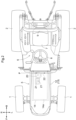
FIG. 2 is a plan view of the electric tractor. -
FIG. 3 is a plan view showing a service plug, a fuse, a first recessed portion in an open state, and a second recessed portion in an open state. -
FIG. 4 is a plan view showing the first recessed portion in a closed state and the second recessed portion in a closed state. -
FIG. 5 is a cross-sectional view taken along line V-V ofFIG. 3 . -
FIG. 6 is a cross-sectional view taken along line VI-VI ofFIG. 3 . -
FIG. 7 is a perspective view of a second coupling bolt. -
FIG. 8 is a perspective view of a hexalobular screw. -
FIG. 9 is a plan view showing a first recessed portion of another embodiment. - An embodiment of an electric tractor, which is an example of a work vehicle according to the present invention, will be described below with reference to the drawings.
- An electric tractor is shown in
FIGS. 1 and2 . This electric tractor is included in various types of working machines, such as a riding tiller formed by coupling a rotary tilling device (not shown) to the body rear portion, or a riding grass cutter formed by coupling a grass cutting device (not shown) to the body lower portion. - The front-rear direction of the travel body of the electric tractor is defined along the body forward travel direction when in the working state, and the left-right direction of the travel body is defined as viewed in the forward travel direction of the travel body. That is, the direction indicated by the symbol (F) in
FIGS. 1 ,2 , and the like is a body front side, and the direction indicated by the symbol (B) inFIGS. 1 ,2 , and the like is a body rear side. The direction indicated by the symbol (L) inFIG. 2 and the like is a body left side, and the direction indicated by the symbol (R) inFIG. 2 and the like is a body right side. Accordingly, the body left-right direction corresponds to a body lateral direction. In addition, the direction indicated by the symbol (U) inFIG. 1 and the like is a body upper side, and the direction indicated by the symbol (D) inFIG. 1 and the like is a body lower side. - The electric tractor includes a
travel body 3 supported by steerable and drivablefront wheels 1 serving as a pair of left and right travel devices, and drivablerear wheels 2 serving as a pair of left and right travel devices. Amotor section 5 including an electric motor 4 for driving thefront wheels 1 and therear wheels 2 is provided at a front portion of thetravel body 3. Adriving section 6 in which an operator sits is provided at a rear portion of thetravel body 3. Thedriving section 6 includes a driver'sseat 7, asteering wheel 8 for steering thefront wheels 1, and aROPS 9 serving as a driver protection device. Abody frame 10 includes, for example, afront frame 11a that supports thefront wheels 1 and the like, and atransmission case 11 whose front portion is coupled to the rear portion of thefront frame 11a and that supports therear wheels 2 and the like. - As shown in
FIGS. 1 ,2 , and6 , themotor section 5 includes abattery room 13 formed by acover member 12. Thebattery room 13 is provided with abattery 14. The electric motor 4 that drives thefront wheels 1 and therear wheels 2 and aninverter 15 that converts DC power from thebattery 14 into AC power and supplies the AC power to the electric motor 4 are provided below thebattery 14. The electric motor 4 and theinverter 15 are arranged in the body front-rear direction with the electric motor 4 on the body rearward side relative to theinverter 15. - The electric motor 4 is supported by the
front frame 11a. The output of the electric motor 4 is input to a hydrostatic continuously variable transmission 17 (seeFIG. 1 ) provided at a front portion of thetransmission case 11 via a rotary shaft 16 (seeFIG. 1 ) extending from the electric motor 4 toward the body rear side, and is then input from the continuouslyvariable transmission 17 to thetransmission case 11. The input power is transmitted to a driving transmission (not shown) and then transmitted from the driving transmission to therear wheels 2 and thefront wheels 1. Power is transmitted from the driving transmission to thefront wheels 1 via arotary shaft 18 extending from thetransmission case 11 toward the body front. - The
battery 14 is placed on a battery placement platform 19 (seeFIG. 1 ) supported by thefront frame 11a. Thebattery 14 is provided with a service plug 20 (seeFIGS. 3 and5 ) and two fuses 21 (seeFIGS. 3 and5 ) by which a power source circuit that uses thebattery 14 as a power source can be shut off. Theinverter 15 is supported by thefront frame 11a below thebattery placement platform 19. - As shown in
FIGS. 1 and2 , thecover member 12 has an opening and closing axis P that is at the end portion on the body rearward side of thecover member 12 and extends in the body lateral direction, and thecover member 12 is supported by asupport frame 22 while being swingable up and down to be opened and closed, with the opening and closing axis P serving as a swing support point. - Specifically, as shown in
FIGS. 3 ,5 , and6 , thesupport frame 22 has a gate shape as viewed from the front, the gate shape surrounding the upper portion of the rear end portion of thebattery 14, and thesupport frame 22 is supported by thefront frame 11a viasupport members 23 provided across intermediate portions of thesupport frame 22 and thefront frame 11a. Bothend portions 22b of thesupport frame 22 are engaged with lateral end portions of thebattery 14 and are supported by thebattery 14. A reinforcingmember 24 is coupled to the inside of the end portion on the body rearward side of thecover member 12. The reinforcingmember 24 has twocoupling portions 24a provided at the left and right sides thereof, and thecoupling portions 24a are supported in such a manner as to be rotatable viasupport point shafts 25 by supportingportions 22a provided at the left and right sides of thesupport frame 22. The axis of thesupport point shaft 25 corresponds to the opening and closing axis P. - As shown in
FIGS. 1 ,5 , and6 , thebattery 14 includes anupper cover portion 14a provided on the upper portion of thebattery 14. Theupper cover portion 14a is configured to cover anelectric circuit portion 14b of thebattery 14. - As shown in
FIGS. 3 ,4 , and5 , a first recessedportion 27 having afirst opening 26 and afirst lid member 28 that opens and closes the first recessedportion 27 by opening and closing thefirst opening 26 are provided at the end portion on the body rearward side of theupper cover portion 14a, which serves as the upper surface portion of thebattery 14. A box-shapedmember 29 that forms a peripheral wall and a bottom wall of the first recessedportion 27 is provided inside theupper cover portion 14a. The service plug 20 configured to shut off a power source circuit that uses thebattery 14 as a power source is accommodated in the first recessedportion 27 and is covered from above by thefirst lid member 28. - In this embodiment, the first recessed
portion 27 is provided at the end portion on the body rearward side of theupper cover portion 14a, but it can also be provided at any part of theupper cover portion 14a, such as the end portion on the body frontward side of theupper cover portion 14a, or the center in the body front-rear direction of theupper cover portion 14a. - As shown in
FIG. 4 , thefirst lid member 28 is configured to be attached to and detached from theupper cover portion 14a byfirst coupling bolts 30 serving as four first screw members. Specifically, two of the fourfirst coupling bolts 30 are configured to fasten and couple thefirst lid member 28 to theupper cover portion 14a by engaging with the part on the left side of thefirst opening 26 in theupper cover portion 14a. The other two of the fourfirst coupling bolts 30 are configured to fasten and couple thefirst lid member 28 to theupper cover portion 14a by engaging with the part on the right side of thefirst opening 26 in theupper cover portion 14a. Thefirst coupling bolts 30 are engaged with theupper cover portion 14a by being engaged with screw hole members fixed to the underside of theupper cover portion 14a. A sealing gasket 31 (seeFIG. 5 ) is interposed between thefirst lid member 28 and theupper cover portion 14a. - The service plug 20 is accommodated in the first recessed
portion 27 and is covered and hidden by thefirst lid member 28 in such a manner as to prevent it from being operated by mistake and to prevent mud and the like splashed up by thefront wheels 1 from adhering thereto. The service plug 20 can be removed upward through thefirst opening 26 by removing thefirst lid member 28 to open thefirst opening 26. - As shown in
FIGS. 3 and5 , thefirst opening 26 is provided with anend portion 26a on the body rearward side of thefirst opening 26 located below the opening and closing axis P of thecover member 12. Compared to a case in which thefirst opening 26 is on the body frontward side relative to the opening and closing axis P, the interval between thecover member 12 and thefirst opening 26 when thecover member 12 is opened can be made narrower. That is, even if thecover member 12 is opened, the interval between thecover member 12 and thefirst lid member 28 is narrow. Therefore, theservice plug 20 can be made more difficult to operate. - As shown in
FIG. 3 , thefirst opening 26 has an octagonal shape. Aperipheral edge 32 of thefirst opening 26 includes a firstperipheral edge portion 32a that corresponds to theend portion 26a on the body rearward side of thefirst opening 26 and extends along the opening and closing axis P in the body lateral direction. Theperipheral edge 32 of thefirst opening 26 includes a secondperipheral edge portion 32b that corresponds to anend portion 26b on the body frontward side of thefirst opening 26 and extends parallel to the firstperipheral edge portion 32a in the body lateral direction. Compared to a case where the first opening is circular, the interval between thecover member 12 and thefirst opening 26 when thecover member 12 is opened can be made narrower, while thefirst opening 26 can be made wider so that theservice plug 20 is easily operated. - As shown in
FIG. 4 , the fourfirst coupling bolts 30 are provided on the body front side relative to the opening and closing axis P of thecover member 12. When opening and closing thefirst lid member 28, thefirst coupling bolts 30 can be operated at a location on the body frontward side relative to the opening and closing axis P, that is, at a location where thecover member 12 is unlikely to interfere with operation. - In this embodiment, two
first coupling bolts 30 are provided on both sides of thefirst opening 26, but it is possible to provide three or morefirst coupling bolts 30 on both sides of thefirst opening 26. In this embodiment, thefirst coupling bolts 30 are used, but it is possible to use a bolt fixed to theupper cover portion 14a and a screw hole member that engages with this bolt to fasten thefirst lid member 28 to theupper cover portion 14a instead of thefirst coupling bolts 30. - As shown in
FIG. 3 , the twofuses 21 are provided in a part of theupper cover portion 14a of thebattery 14 that is adjacent to theservice plug 20. Since the twofuses 21 and theservice plug 20 are close to each other, when performing maintenance work on the twofuses 21, it is easy to operate theservice plug 20 and shut off the power source circuit. - Specifically, as shown in
FIGS. 3 and5 , a second recessedportion 33 separate from the first recessedportion 27 is provided in a part of theupper cover portion 14a adjacent to the front of the first recessedportion 27. The second recessedportion 33 is provided with asecond opening 34 separate from thefirst opening 26. The second recessedportion 33 is opened and closed by opening and closing thesecond opening 34 with asecond lid member 35 separate from thefirst lid member 28. The two fuses 21 are accommodated in the second recessedportion 33 and are covered from above by asecond lid member 35. The two fuses 21 can remain covered by thesecond lid member 35 while theservice plug 20 is operated. The two fuses 21 are accommodated in the second recessedportion 33 by attaching the twofuses 21 to afuse support platform 36 provided in the second recessedportion 33. - As shown in
FIG. 4 , thesecond lid member 35 is configured to be attached to and detached from theupper cover portion 14a bysecond coupling bolts 37 serving as four second screw members. Specifically, two of the foursecond coupling bolts 37 are configured to fasten and couple thesecond lid member 35 to theupper cover portion 14a by engaging with parts on both sides of the end portion on the body rearward side of thesecond opening 34 in theupper cover portion 14a. The other two of the foursecond coupling bolts 37 are configured to fasten and couple thesecond lid member 35 to theupper cover portion 14a by engaging with parts on both sides of the end portion on the body frontward side of thesecond opening 34 in theupper cover portion 14a. Thesecond coupling bolt 37 is engaged with theupper cover portion 14a due to thesecond coupling bolts 37 engaging with screw hole members fixed to the underside of theupper cover portion 14a. A sealing gasket 41 (seeFIG. 5 ) is interposed between thesecond lid member 35 and theupper cover portion 14a. - Three
second coupling bolts 37a of the foursecond coupling bolts 37 are constituted by coupling bolts havinghexagonal heads 38 as shown inFIG. 7 . Anothersecond coupling bolt 37b of the foursecond coupling bolts 37 is constituted by a hexalobular screw having ahead 39 provided with ahexagonal attachment hole 40, as shown inFIG. 8 . The hexalobular screw is used to fasten the end portion on the body frontward side of thesecond lid member 35, that is, the end portion farther from the opening and closing axis P of thecover member 12. - In this embodiment, four
second coupling bolts 37 are provided. However, six or moresecond coupling bolts 37 can be provided. In this embodiment, thesecond coupling bolts 37 are used, but it is possible to use a screw shaft fixed to theupper cover portion 14a and a screw hole member that engages with this screw shaft to fasten thesecond lid member 35 to theupper cover portion 14a instead of thesecond coupling bolts 37. -
- (1)
FIG. 9 is a plan view showing a first recessedportion 27 of an alternative embodiment. In the first recessedportion 27 of the alternative embodiment, thefirst opening 26 of the first recessedportion 27 has a quadrangular shape. Theperipheral edge 32 of thefirst opening 26 includes the firstperipheral edge portion 32a that corresponds to one rearward side of thefirst opening 26 and is located below the opening and closing axis P along the opening and closing axis P. Thefirst coupling bolts 30 for fastening and coupling thefirst lid member 28 are respectively attached to theupper cover portion 14a at locations corresponding to the four corners of thefirst opening 26. In this embodiment, thefirst opening 26 has a rectangular shape with four chamfered corners, but the corners need not be chamfered. Note that the non-circular shape of thefirst opening 26 is not limited to an octagonal shape or a quadrangular shape, and can have a hexagonal shape or the like. - (2) In the above embodiment, an example was shown in which the first recessed
portion 27 was provided at the end portion on the body rearward side of theupper cover portion 14a. However, the first recessedportion 27 may be provided at any part of theupper cover portion 14a, such as the end portion on the body frontward side of theupper cover portion 14a or an intermediate portion in the body front-rear direction of theupper cover portion 14a. - (3) In the above embodiment, an example was shown in which the
first opening 26 had an octagonal shape. However, the shape is not limited to this, and it is possible to employ a first opening that has a non-circular shape, such as a hexagonal shape. - (4) In the above embodiment, an example was shown in which two
fuses 21 were provided. However, it is also possible to provide only one fuse or three or more fuses. - (5) In the above embodiment, an example was shown in which the
fuse 21 was adjacent to the front of theservice plug 20. However, thefuse 21 may also be adjacent to the side of theservice plug 20. - (6) In the above embodiment, an example was shown in which the first recessed
portion 27 and the second recessedportion 33 were provided separately from each other and thefirst lid member 28 and thesecond lid member 35 were provided separately from each other. However, there is no limitation to this. For example, theservice plug 20 and thefuse 21 may also be accommodated in the same recessed portion. Also, the first recessedportion 27 and the second recessedportion 33 may be provided separately from each other, and thefirst opening 26 of the first recessedportion 27 and thesecond opening 34 of the second recessedportion 33 may be opened and closed by the same lid member. - (7) In the above embodiment, an example was shown in which a hexalobular screw was used, but a configuration in which a hexalobular screw is not used is also possible.
- (8) In the above embodiment, an example was shown in which the
front wheels 1 and therear wheels 2 were provided, but a crawler travel device or a mini crawler may also be provided as the travel device. - The present invention can be applied to a work vehicle including an electric motor that drives a travel device, a battery room formed by an openable and closable cover member, and a battery that is provided in the battery room and supplies power to the electric motor.
-
- 1: front wheel (travel device)
- 2: rear wheel (travel device)
- 4: electric motor
- 12: cover member
- 13: battery room
- 14: battery
- 14a: upper cover portion (upper surface portion)
- 20: service plug
- 21: fuse
- 26: first opening (opening)
- 26a: end portion
- 26b: end portion
- 27: first recessed portion (recessed portion)
- 28: first lid member (lid member)
- 30: first coupling bolt (screw member)
- 32: peripheral edge
- 32a: first peripheral edge portion
- 32b: second peripheral edge portion
- 33: second recessed portion
- 34: second opening
- 35: second lid member
- 37b: second coupling bolt (hexalobular screw)
Claims (9)
- A work vehicle comprising:an electric motor configured to drive a travel device;a battery room formed by an openable and closable cover member;a battery provided in the battery room and configured to supply power to the electric motor; anda service plug configured to shut off a power source circuit that uses the battery as a power source,wherein a recessed portion and a lid member configured to open and close the recessed portion are provided on an upper surface portion of the battery, andthe service plug is accommodated in the recessed portion and is covered from above by the lid member.
- The work vehicle according to claim 1,wherein the cover member is supported in such a manner as to be swingable up and down to be opened and closed using, as a swing support point, an opening and closing axis that is at an end portion on a body rearward side of the cover member and extends along a body lateral direction, andthe end portion on the body rearward side of the opening of the recessed portion is below the opening and closing axis.
- The work vehicle according to claim 2,wherein the opening is non-circular, anda peripheral edge of the opening includes a first peripheral edge portion that corresponds to the end portion on the body rearward side of the opening and extends in the body lateral direction along the opening and closing axis, and the peripheral edge of the opening includes a second peripheral edge portion that corresponds to an end portion on a body frontward side of the opening and extends in the body lateral direction parallel to the first peripheral edge portion.
- The work vehicle according to claim 2 or 3,
wherein the opening has an octagonal shape. - The work vehicle according to any one of claims 2 to 4,wherein both sides of the opening include screw members configured to fasten the lid member to the upper surface portion, andthe screw members are provided on a body front side relative to the opening and closing axis.
- The work vehicle according to any one of claims 1 to 5,
wherein a power source fuse is provided adjacent to the service plug. - The work vehicle according to claim 6,
wherein the fuse is on the body front side relative to the service plug. - The work vehicle according to claim 6 or 7,wherein the upper surface portion is provided with a second recessed portion separate from the recessed portion, and a second lid member that is configured to open and close the second recessed portion and is separate from the lid member, andthe fuse is accommodated in the second recessed portion and is covered from above by the second lid member.
- The work vehicle according to claim 8, further comprising
a hexalobular screw configured to fasten the second lid member to the upper surface portion.
Applications Claiming Priority (2)
| Application Number | Priority Date | Filing Date | Title |
|---|---|---|---|
| JP2022124179A JP7809029B2 (en) | 2022-08-03 | 2022-08-03 | Work vehicle |
| PCT/JP2023/004877 WO2024029109A1 (en) | 2022-08-03 | 2023-02-14 | Work vehicle |
Publications (1)
| Publication Number | Publication Date |
|---|---|
| EP4566893A1 true EP4566893A1 (en) | 2025-06-11 |
Family
ID=89848951
Family Applications (1)
| Application Number | Title | Priority Date | Filing Date |
|---|---|---|---|
| EP23849677.2A Pending EP4566893A1 (en) | 2022-08-03 | 2023-02-14 | Work vehicle |
Country Status (4)
| Country | Link |
|---|---|
| EP (1) | EP4566893A1 (en) |
| JP (1) | JP7809029B2 (en) |
| CN (1) | CN119630560A (en) |
| WO (1) | WO2024029109A1 (en) |
Family Cites Families (9)
| Publication number | Priority date | Publication date | Assignee | Title |
|---|---|---|---|---|
| JP2015050034A (en) | 2013-09-02 | 2015-03-16 | コベルコ建機株式会社 | Power storage device |
| JP5854012B2 (en) | 2013-09-13 | 2016-02-09 | トヨタ自動車株式会社 | Service hole cover and vehicle unit mounting structure |
| JP6392718B2 (en) | 2015-09-07 | 2018-09-19 | トヨタ自動車株式会社 | Protective cover for vehicle battery pack service plug |
| JP6267749B2 (en) | 2016-07-04 | 2018-01-24 | 中島特殊鋼株式会社 | Nuts and special tools |
| JP7093700B2 (en) | 2018-08-30 | 2022-06-30 | 矢崎総業株式会社 | Battery cover |
| JP7020370B2 (en) | 2018-10-30 | 2022-02-16 | トヨタ自動車株式会社 | Battery pack |
| JP7176939B2 (en) | 2018-12-07 | 2022-11-22 | 矢崎総業株式会社 | Power supply unit |
| JP2021030962A (en) | 2019-08-28 | 2021-03-01 | トヨタ自動車株式会社 | Electric vehicle |
| JP7524020B2 (en) | 2020-10-05 | 2024-07-29 | 株式会社クボタ | Electric Tractor |
-
2022
- 2022-08-03 JP JP2022124179A patent/JP7809029B2/en active Active
-
2023
- 2023-02-14 EP EP23849677.2A patent/EP4566893A1/en active Pending
- 2023-02-14 WO PCT/JP2023/004877 patent/WO2024029109A1/en not_active Ceased
- 2023-02-14 CN CN202380056675.5A patent/CN119630560A/en active Pending
Also Published As
| Publication number | Publication date |
|---|---|
| JP7809029B2 (en) | 2026-01-30 |
| JP2024021386A (en) | 2024-02-16 |
| WO2024029109A1 (en) | 2024-02-08 |
| CN119630560A (en) | 2025-03-14 |
Similar Documents
| Publication | Publication Date | Title |
|---|---|---|
| CN111194371B (en) | Electric construction machine | |
| EP3470583B1 (en) | Tractor | |
| JP7675643B2 (en) | electric work vehicle | |
| WO2024142480A1 (en) | Electric work vehicle | |
| US20250289333A1 (en) | Electric work vehicle | |
| US20250286321A1 (en) | Electric work vehicle | |
| JP7720960B2 (en) | electric work vehicle | |
| JP7789124B2 (en) | electric work vehicle | |
| JP7809029B2 (en) | Work vehicle | |
| JP2024101025A5 (en) | ||
| JP7675642B2 (en) | electric work vehicle | |
| EP4364988A1 (en) | Electric work vehicle | |
| EP4454915A1 (en) | Electric work vehicle | |
| JP7546543B2 (en) | Electric work vehicle | |
| EP3289851B1 (en) | Work vehicle | |
| JP3132768U (en) | Protective plate | |
| JP7565908B2 (en) | Electric work vehicle | |
| JP6507119B2 (en) | Work vehicle | |
| JP6606463B2 (en) | Work vehicle | |
| JP7550744B2 (en) | Electric work vehicle | |
| JP4370876B2 (en) | Tractor | |
| US20250289334A1 (en) | Electric work vehicle | |
| JP7519982B2 (en) | Electric work vehicle | |
| WO2023119936A1 (en) | Electric work vehicle | |
| JP2007309267A (en) | Working vehicle |
Legal Events
| Date | Code | Title | Description |
|---|---|---|---|
| STAA | Information on the status of an ep patent application or granted ep patent |
Free format text: STATUS: THE INTERNATIONAL PUBLICATION HAS BEEN MADE |
|
| PUAI | Public reference made under article 153(3) epc to a published international application that has entered the european phase |
Free format text: ORIGINAL CODE: 0009012 |
|
| STAA | Information on the status of an ep patent application or granted ep patent |
Free format text: STATUS: REQUEST FOR EXAMINATION WAS MADE |
|
| 17P | Request for examination filed |
Effective date: 20250206 |
|
| AK | Designated contracting states |
Kind code of ref document: A1 Designated state(s): AL AT BE BG CH CY CZ DE DK EE ES FI FR GB GR HR HU IE IS IT LI LT LU LV MC ME MK MT NL NO PL PT RO RS SE SI SK SM TR |
|
| DAV | Request for validation of the european patent (deleted) | ||
| DAX | Request for extension of the european patent (deleted) |