EP4566866A1 - Schnellladestation für elektrofahrzeuge - Google Patents
Schnellladestation für elektrofahrzeuge Download PDFInfo
- Publication number
- EP4566866A1 EP4566866A1 EP24211619.2A EP24211619A EP4566866A1 EP 4566866 A1 EP4566866 A1 EP 4566866A1 EP 24211619 A EP24211619 A EP 24211619A EP 4566866 A1 EP4566866 A1 EP 4566866A1
- Authority
- EP
- European Patent Office
- Prior art keywords
- power
- module
- modules
- charging station
- control
- Prior art date
- Legal status (The legal status is an assumption and is not a legal conclusion. Google has not performed a legal analysis and makes no representation as to the accuracy of the status listed.)
- Pending
Links
Images



Classifications
-
- B—PERFORMING OPERATIONS; TRANSPORTING
- B60—VEHICLES IN GENERAL
- B60L—PROPULSION OF ELECTRICALLY-PROPELLED VEHICLES; SUPPLYING ELECTRIC POWER FOR AUXILIARY EQUIPMENT OF ELECTRICALLY-PROPELLED VEHICLES; ELECTRODYNAMIC BRAKE SYSTEMS FOR VEHICLES IN GENERAL; MAGNETIC SUSPENSION OR LEVITATION FOR VEHICLES; MONITORING OPERATING VARIABLES OF ELECTRICALLY-PROPELLED VEHICLES; ELECTRIC SAFETY DEVICES FOR ELECTRICALLY-PROPELLED VEHICLES
- B60L53/00—Methods of charging batteries, specially adapted for electric vehicles; Charging stations or on-board charging equipment therefor; Exchange of energy storage elements in electric vehicles
- B60L53/10—Methods of charging batteries, specially adapted for electric vehicles; Charging stations or on-board charging equipment therefor; Exchange of energy storage elements in electric vehicles characterised by the energy transfer between the charging station and the vehicle
- B60L53/11—DC charging controlled by the charging station, e.g. mode 4
-
- B—PERFORMING OPERATIONS; TRANSPORTING
- B60—VEHICLES IN GENERAL
- B60L—PROPULSION OF ELECTRICALLY-PROPELLED VEHICLES; SUPPLYING ELECTRIC POWER FOR AUXILIARY EQUIPMENT OF ELECTRICALLY-PROPELLED VEHICLES; ELECTRODYNAMIC BRAKE SYSTEMS FOR VEHICLES IN GENERAL; MAGNETIC SUSPENSION OR LEVITATION FOR VEHICLES; MONITORING OPERATING VARIABLES OF ELECTRICALLY-PROPELLED VEHICLES; ELECTRIC SAFETY DEVICES FOR ELECTRICALLY-PROPELLED VEHICLES
- B60L53/00—Methods of charging batteries, specially adapted for electric vehicles; Charging stations or on-board charging equipment therefor; Exchange of energy storage elements in electric vehicles
- B60L53/30—Constructional details of charging stations
-
- B—PERFORMING OPERATIONS; TRANSPORTING
- B60—VEHICLES IN GENERAL
- B60L—PROPULSION OF ELECTRICALLY-PROPELLED VEHICLES; SUPPLYING ELECTRIC POWER FOR AUXILIARY EQUIPMENT OF ELECTRICALLY-PROPELLED VEHICLES; ELECTRODYNAMIC BRAKE SYSTEMS FOR VEHICLES IN GENERAL; MAGNETIC SUSPENSION OR LEVITATION FOR VEHICLES; MONITORING OPERATING VARIABLES OF ELECTRICALLY-PROPELLED VEHICLES; ELECTRIC SAFETY DEVICES FOR ELECTRICALLY-PROPELLED VEHICLES
- B60L53/00—Methods of charging batteries, specially adapted for electric vehicles; Charging stations or on-board charging equipment therefor; Exchange of energy storage elements in electric vehicles
- B60L53/60—Monitoring or controlling charging stations
- B60L53/62—Monitoring or controlling charging stations in response to charging parameters, e.g. current, voltage or electrical charge
-
- B—PERFORMING OPERATIONS; TRANSPORTING
- B60—VEHICLES IN GENERAL
- B60L—PROPULSION OF ELECTRICALLY-PROPELLED VEHICLES; SUPPLYING ELECTRIC POWER FOR AUXILIARY EQUIPMENT OF ELECTRICALLY-PROPELLED VEHICLES; ELECTRODYNAMIC BRAKE SYSTEMS FOR VEHICLES IN GENERAL; MAGNETIC SUSPENSION OR LEVITATION FOR VEHICLES; MONITORING OPERATING VARIABLES OF ELECTRICALLY-PROPELLED VEHICLES; ELECTRIC SAFETY DEVICES FOR ELECTRICALLY-PROPELLED VEHICLES
- B60L53/00—Methods of charging batteries, specially adapted for electric vehicles; Charging stations or on-board charging equipment therefor; Exchange of energy storage elements in electric vehicles
- B60L53/60—Monitoring or controlling charging stations
- B60L53/67—Controlling two or more charging stations
-
- Y—GENERAL TAGGING OF NEW TECHNOLOGICAL DEVELOPMENTS; GENERAL TAGGING OF CROSS-SECTIONAL TECHNOLOGIES SPANNING OVER SEVERAL SECTIONS OF THE IPC; TECHNICAL SUBJECTS COVERED BY FORMER USPC CROSS-REFERENCE ART COLLECTIONS [XRACs] AND DIGESTS
- Y02—TECHNOLOGIES OR APPLICATIONS FOR MITIGATION OR ADAPTATION AGAINST CLIMATE CHANGE
- Y02T—CLIMATE CHANGE MITIGATION TECHNOLOGIES RELATED TO TRANSPORTATION
- Y02T10/00—Road transport of goods or passengers
- Y02T10/60—Other road transportation technologies with climate change mitigation effect
- Y02T10/70—Energy storage systems for electromobility, e.g. batteries
-
- Y—GENERAL TAGGING OF NEW TECHNOLOGICAL DEVELOPMENTS; GENERAL TAGGING OF CROSS-SECTIONAL TECHNOLOGIES SPANNING OVER SEVERAL SECTIONS OF THE IPC; TECHNICAL SUBJECTS COVERED BY FORMER USPC CROSS-REFERENCE ART COLLECTIONS [XRACs] AND DIGESTS
- Y02—TECHNOLOGIES OR APPLICATIONS FOR MITIGATION OR ADAPTATION AGAINST CLIMATE CHANGE
- Y02T—CLIMATE CHANGE MITIGATION TECHNOLOGIES RELATED TO TRANSPORTATION
- Y02T10/00—Road transport of goods or passengers
- Y02T10/60—Other road transportation technologies with climate change mitigation effect
- Y02T10/7072—Electromobility specific charging systems or methods for batteries, ultracapacitors, supercapacitors or double-layer capacitors
-
- Y—GENERAL TAGGING OF NEW TECHNOLOGICAL DEVELOPMENTS; GENERAL TAGGING OF CROSS-SECTIONAL TECHNOLOGIES SPANNING OVER SEVERAL SECTIONS OF THE IPC; TECHNICAL SUBJECTS COVERED BY FORMER USPC CROSS-REFERENCE ART COLLECTIONS [XRACs] AND DIGESTS
- Y02—TECHNOLOGIES OR APPLICATIONS FOR MITIGATION OR ADAPTATION AGAINST CLIMATE CHANGE
- Y02T—CLIMATE CHANGE MITIGATION TECHNOLOGIES RELATED TO TRANSPORTATION
- Y02T90/00—Enabling technologies or technologies with a potential or indirect contribution to GHG emissions mitigation
- Y02T90/10—Technologies relating to charging of electric vehicles
- Y02T90/12—Electric charging stations
Definitions
- the present invention relates to a rapid charging station for electric vehicles according to the preamble of claim 1, a method for controlling a rapid charging station according to the preamble of claim 13 and a power module configured for use in a rapid charging station according to claim 14.
- Fast charging stations also known as high-performance chargers, are direct current charging stations for electric vehicles, especially automobiles, but also trucks, ships and the like.
- Fast charging stations such as the Hypercharger from Alpitronic, are known to have multiple power modules.
- Each power module has a converter arrangement that converts an AC voltage at the input into a DC voltage at the output. Instead of one converter arrangement for the entire fast charging station, several are used. This allows, for example, flexible distribution of the power modules across connection points, smaller and possibly more efficient power electronics, and the like.
- the power modules have output connections to which the power module delivers electrical power with controlled output parameters.
- the output connections of at least two power modules are connected in parallel to form a first group to deliver electrical power to at least one connection point of the fast charging station.
- the challenge is to improve the known state of the art and to provide an efficient and cost-effective control concept.
- the invention is based on the problem of designing and developing the known fast charging stations in such a way that further optimization is achieved with regard to the aforementioned challenge.
- the fundamental idea is that one power module can be used as the primary module and at least one other, usually all, power modules as the secondary module.
- the primary module is assigned the task of providing overall control for at least one electrical parameter, usually voltage, current, or power, of the connection point, while the secondary modules control their own parameters.
- the primary module takes over the first reaction and ensures that the electrical parameters at the connection point are adapted to the new power requirement.
- Any existing power control unit can thus be connected with less computing power and a slower communication connection, as it is not involved in the initial reaction. Communication between the power modules, if any, is also possible. present, does not have to be fast enough to react to sudden changes at the connection point.
- the first group in particular always exactly, has a primary module and at least one secondary module, that the power modules each have a control module which controls the converter arrangement of the respective power module, that the control module of the primary module takes over an overall control for the connection point, that the control module or the control modules of the secondary module or the secondary modules control at least one of their output parameters.
- the primary module regulates the total voltage by regulating its own output voltage and/or the secondary module regulates its output current. Changes at the connection point are thus easily compensated for by the primary module alone, while the secondary modules simply continue to provide their current at the initial moment.
- Claim 3 relates to preferred embodiments of the power module as a unit with its control module. If the control module is not separated from the rest of the power module, the entire power module can be easily replaced, and delays due to communication paths for measured values and manipulated variables are very minimal.
- Claims 4 to 10 relate to embodiments of the rapid charging station with a central power control unit.
- the power control unit can create control specifications for the power modules and thus, in particular, assign an output current to each of the secondary modules.
- Such a configuration simplifies the overall control and allows, for example, the primary module and the secondary modules to be identical without each having to exhibit the functionality of the power control unit.
- the power control unit can distribute a target output current specified by the electric vehicle.
- the primary module also participates in current regulation, albeit in a different manner.
- a total current sensor may be provided that measures the output current of the connection point. These measured values are then preferably forwarded by the power control unit to the primary module, so that the primary module can also regulate the total current.
- the power control unit creates the control specifications in such a way that the primary module has a high control reserve for abrupt changes at the connection point.
- the efficiency of the allocation of power modules to the connection point is taken into account. For example, using two power modules at 50% of their power may be more efficient than using one power module at 100% of its power.
- the allocation can be adjusted during the charging process based on efficiency considerations.
- Claim 9 relates to an embodiment in which the power control unit is connected to the power modules via a bus, in particular a CAN bus. Communication preferably occurs more slowly than would be necessary for control by the power control unit.
- the power control unit can also take an ageing metric into account when assigning the power modules to the connection point, so that, for example, an older power module is subjected to less load (claim 10).
- a particularly preferred embodiment according to claim 11 relates to the possibility of freely selecting the primary module from the power modules, whereby the rapid charging station can continue to be used even if a power module fails.
- connection point can be provided.
- the first group in particular always exactly, has a primary module and at least one secondary module, that the power modules each have a control module that controls the converter arrangement of the respective power module, that the control module of the primary module takes over an overall control for the connection point, that the control module or the control modules of the secondary module or the secondary modules control at least one of their output parameters.
- a power module is claimed which is designed for use in a rapid charging station according to the proposal.
- Fig. 1 shows an external view of a proposed rapid charging station 1 for electric vehicles 2.
- This station has at least one connection point 3 for an electric vehicle 2, in this case a permanently attached charging cable.
- the rapid charging station 1 has at least, in this case precisely two, connection points 3.
- a rapid charging station 1 is used to charge an electric vehicle 2 using direct current and a power output of usually at least 50 kW.
- the rapid charging station 1 is typically connected to an alternating current network for this purpose.
- the rapid charging station 1 has at least one individually manageable power module 4.
- the rapid charging station 1 has seven power modules 4, each of which provides a portion of the total power of the rapid charging station 1, for example, 30 kW each.
- the power modules 4 can be distributed here, preferably flexibly, among the connection points 3.
- Power module 4 for example, weighs approximately 39 kg, making it difficult to handle. However, it can be removed individually, and the components of power module 4 are not installed individually in fast charging station 1.
- the exemplary embodiment illustrated in the figures and thus preferred relates to a rapid charging station 1 for electric vehicles 2, wherein the rapid charging station 1 has a plurality of power modules 4, wherein the power modules 4 each have a power converter arrangement 5, in particular for converting an alternating voltage as the input voltage of the rapid charging station 1 into a direct voltage as the output voltage of the rapid charging station 1. It is also conceivable that an AC/DC converter is provided for all power modules and separate DC/DC converters are provided in the power module 4.
- the power modules 4 have output connections 6, at which the power module 4 delivers electrical power with regulated output parameters.
- the regulated output parameters can in particular comprise the voltage and/or the current.
- the output connections 6 of at least two power modules 4 are connected in parallel to a first group 7 to deliver electrical power to at least one connection point 3 of the rapid charging station 1.
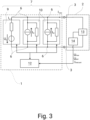
- Fig. 3 shows this parallel connection schematically for three power modules 4. In some constellations, particularly during some charging processes or at the end of a charging process, it may happen that only one power module 4 delivers power to a connection point 3. This case is possible with the proposed rapid charging station 1, but the following considers the control of the power modules 4 when at least two power modules 4 deliver power to the connection point 3. In the parallel connection, the currents of the power modules 4 add up, while the voltages must generally be approximately equal.
- the power electronics comprise a rectifier and a downstream DC-DC converter, which are not shown in detail. Visible in the upper area of the rapid charging station 1 are DC voltage rails 8 for distributing the output power of the power modules 4 to the connection points 3. The AC voltage input is located in the lower area and is not shown.
- the first group 7 has a primary module 9 and at least one secondary module 10.
- the first group 7 always has exactly one primary module 9.
- no secondary module 10 is necessary, but for the cases considered, at least one is present.
- the power modules 4 each have a control module 11 that controls the power converter arrangement 5 of the respective power module 4.
- the control module 11 of the primary module 9 assumes overall control for the connection point 3, and the control module 11 or the control modules 11 of the secondary module 10 or the secondary modules 10 control at least one of their output parameters.
- the control of the output parameter of the secondary module 10 or the secondary modules 10 is preferably carried out such that this output parameter is not an output parameter of the connection point 3.
- the primary module 9 regulates the total voltage of connection point 3, in particular by regulating its output voltage, and thus functions as a voltage source, and/or the secondary module 10 regulates its output current and thus functions as a current source, or the secondary modules 10 regulate their output current and thus function as current sources.
- the primary module 9 therefore regulates its voltage, which, in a parallel connection, essentially corresponds to the voltage of connection point 3.
- the secondary modules 10 regulate the current, which is added to the current of the other secondary modules 10 and the primary module 9 and is therefore not an output parameter of connection point 3.
- control module 11 of the respective power module 4 forms a unit with the power module 4, in particular is arranged in the power module 4. It is conceivable that the control module 11 has its own housing, which is connected to a housing of the power electronics. Preferably, however, the power module 4 has an outer housing in which the control module 11 and the power electronics are arranged. This makes the signal paths particularly short. The unit can be handled individually as such.
- the power modules 4 each have an output current sensor and an output voltage sensor, which form a unit with the power module 4.
- the data flow between the output current sensor and/or the output voltage sensor and the control module 11 runs within the unit, in particular within the power module 4.
- the rapid charging station 1 has a power control unit 12.
- the rapid charging station 1 has exactly one power control unit 12, which manages all power modules 4 and all connection points 3.
- the power control unit 12 creates control specifications for the power modules 4. Preferably, the power control unit 12 distributes an output power at the connection point 3 via the control specification to the Power modules 4. It can be provided that the power control unit 12 indirectly distributes the output power at connection point 3 and creates an output current per secondary module 10 as a reference variable for the secondary modules 10. If the secondary modules 10 operate as a power source as mentioned above, they preferably implement this reference variable directly via their control modules 11, unless safety mechanisms such as voltage limitation or the like preclude this.
- Control variables of the control modules 11 of both the secondary modules 10 and the primary module 9 are here and preferably parameters of a PWM, in particular a phase angle and a duty cycle of a phase shift control, in particular a dual active bridge, of a DC/DC converter of the power converter arrangement 5.
- Fig. 3 a battery 13 of the electric vehicle 2 and a battery management system 14 of the electric vehicle 2, which can communicate with the fast charging station 1.
- the power control unit 12 receives a target output current from the electric vehicle 2, and preferably a target voltage and a maximum voltage.
- the power control unit 12 distributes the target output current to the power modules 4, at least in one operating mode.
- the rapid charging station 1 then maintains a current control based on the target current until the maximum voltage is reached.
- the target voltage can be informative and used for safety purposes and/or to start the controls of the control modules 11.
- the power control unit 12 preferably assigns an output current as a reference variable to the secondary module(s) 10 and communicates the total current to the primary module 9. The latter will be explained in more detail below.
- the primary module 9 additionally regulates the total current of the connection point 3.
- the rapid charging station 1 has a total current sensor 15 per connection point 3, which is connected to the power control unit 12 and that the power control unit 12 forwards a sensor signal of the total current sensor 15, in particular directly or as a control deviation, to the primary module 9.
- the primary module 9 derives the reference variable for the control of the total voltage as a manipulated variable from the control of the total current.
- FIG. 5 A look at Fig. 5 allows an explanation of this control principle.
- the index P for current (I) and voltage (U) stands for the primary module 9, and the index S for the secondary modules 10, of which two are present here as an example (S1, S2).
- the secondary modules 10 regulate their current
- the primary module 9 regulates the total voltage.
- the primary module 9 receives measured values from the total current sensor 15 via the power control unit 12 and compensates for control deviations of the total current by adjusting the voltage.
- the fact that the path via the power control unit 12 is considerably slower than the internal control of the power module 4 is irrelevant. Slow changes in the current requirement can thus be implemented.
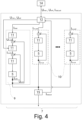
- Fig. 4 In primary module 9, after the voltage regulation, a current regulation is shown, which is provided here and preferably and ensures, for example, compliance with a maximum current. However, this is optional; its function can also be implemented differently.
- this request may become effective electrically directly at the rapid charging station 1 without any timely communication. Regulation via the power control unit 12 would be significantly delayed in this case and could lead to the termination of the charging process. Initially, this request may lead to a drop in the voltage at connection point 3. However, the voltage regulation of the primary module 9 then immediately compensates for this drop in voltage (Phase III). At this point in time, the current setpoint coming from the power control unit 12 may still be at the previous level due to the slower response, so that the overall current regulation of the primary module 9 does not intervene. The total current at connection point 3 is thus briefly increased by the voltage regulation.
- the power control unit 12 reacts subsequently or during this time with a delay, either by forwarding the measured value from the total current sensor 15, whereby the overall current regulation in the primary module 9 reduces the voltage setpoint. and the total current is regulated back to the original value, or the power control unit 12 increases the total current setting, for example, due to communication with electric vehicle 2 (Phase IV).
- the total current regulation could, in principle, also be arranged in the power control unit 12.
- the secondary modules 10 do not respond or hardly respond.
- the power control unit 12 creates the control specifications in such a way that the primary module 9 has a higher two-sided control reserve than the secondary module or modules 10.
- the primary module 9 has, for example, when utilizing 60% to 80%, preferably 40% to 80%, more preferably 20% to 90% of the total power of the rapid charging station 1 at one connection point 3, while the other is unoccupied, a higher control reserve than each secondary module 10. If the primary module 9 is already at the limit of its power, it cannot react in one direction.
- each power module 4 can provide, for example, 60 A and a total of 160 A are required from three power modules 4, the secondary modules 10 would each provide, for example, 60 A and the primary module 9 would provide 40 A, whereby the primary module 9 still has a control reserve of 20 A upwards and 40 A downwards.
- the power control unit 12 establishes the control specifications such that the primary module 9 has the same control reserve plus or minus a maximum of 5%, preferably a maximum of 2%, in both directions in the event of an abrupt increase or decrease in the electrical power demanded by the electric vehicle 2.
- the control reserve can relate to the current and/or the voltage and/or the power, here and preferably the power or the current.
- the power control unit 12 selects a subset from the available power modules 4 according to an efficiency algorithm and assigns it to the connection point 3. For example, it may be more efficient to operate four power modules 4 at approximately 50% of their maximum power than two power modules 4 at approximately 100% of their maximum power.
- Fig. 5 shows a decrease in the charging current in phase V and, at the beginning of phase VI, the switching off of one power module 4 and simultaneous increase of the other power modules 4 (idealized).
- the power control unit 12 adjusts the subset during the charging process according to an efficiency algorithm.
- the power control unit 12 communicates with the power modules 4 via a bus, in particular a CAN bus, and preferably that the control specifications and/or the sensor signal of the total current sensor 15 are transmitted via the bus.
- a CAN bus in particular, is relatively slow, robust against electrical interference fields, and inexpensive, and therefore well suited for use in this case.
- the power control unit 12 may select a subset of the available power modules 4 based on an aging metric of the power modules 4 and assign it to the connection point 3, and/or for the power control unit 12 to determine the control specifications based on the aging metric of the power modules 4, preferably in such a way that the power control unit 12 assigns different output currents to the secondary modules 10 as reference variables. Older power modules 4 can thus be protected, for example to enable joint maintenance or joint replacement.
- the aging metric here and preferably refers to the operating hours, in particular relative to the load during operation.
- control modules 11 of the power modules 4 are similar, in particular identical, such that the primary module 9 can be freely selected from the power modules 4 selected for a connection point 3.
- no dedicated primary module 9 is provided that differs in any way from the other power modules 4, but rather that each power module 4 can function as a primary module 9.
- a power module 4 that was used as the primary module 9 fails, another power module 4 is used as the primary module 9.
- the rapid charging station 1 can continue to be used even if one or more power modules 4 are defective.
- the rapid charging station 1 has at least one further connection point 3, that the output connections 6 of at least two power modules 4 for delivering electrical Power at the further connection point 3 of the rapid charging station 1 can be connected in parallel to a second group, that at least one power module 4, preferably all power modules 4, can be assigned optionally to the first group 7 or the second group, and that the second group, in particular always has exactly one primary module 9 and at least one secondary module 10.
- a method for controlling a proposed rapid charging station 1 for electric vehicles 2 is proposed, wherein the rapid charging station 1 has a plurality of power modules 4, wherein the power modules 4 each have a power converter arrangement 5, in particular for converting an alternating voltage as the input voltage of the rapid charging station 1 into a direct voltage as the output voltage of the rapid charging station 1, wherein the power modules 4 have output connections 6, at which the power module 4 delivers electrical power with regulated output parameters, wherein the output connections 6 of at least two power modules 4 are connected in parallel to form a first group 7 for delivering electrical power to at least one connection point 3 of the rapid charging station 1.
- the first group 7 in particular always exactly, has a primary module 9 and at least one secondary module 10, that the power modules 4 each have a control module 11 which controls the power converter arrangement 5 of the respective power module 4, that the control module 11 of the primary module 9 takes over an overall control for the connection point 3, that the control module 11 or the control modules 11 of the secondary module 10 or the secondary modules 10 control at least one of their output parameters.
- a power module 4 is set up for use in a proposed rapid charging station 1.
- the power module 4 has a control module 11 which is configured such that the power module 4 can be used as a primary module 9 and as a secondary module 10.
Landscapes
- Engineering & Computer Science (AREA)
- Power Engineering (AREA)
- Transportation (AREA)
- Mechanical Engineering (AREA)
- Charge And Discharge Circuits For Batteries Or The Like (AREA)
- Electric Propulsion And Braking For Vehicles (AREA)
Abstract
Die Erfindung betrifft eine Schnellladestation für Elektrofahrzeuge (2), wobei die Schnellladestation (1) mehrere Leistungsmodule (4) aufweist, wobei die Leistungsmodule (4) jeweils eine Stromrichteranordnung (5) insbesondere zur Wandlung einer Wechselspannung als Eingangsspannung der Schnellladestation (1) in eine Gleichspannung als Ausgangsspannung der Schnellladestation (1) aufweisen, wobei die Leistungsmodule (4) Ausgangsanschlüsse (6) aufweisen, an denen das Leistungsmodul (4) elektrische Leistung mit geregelten Ausgangsparametern abgibt, wobei die Ausgangsanschlüsse (6) von mindestens zwei Leistungsmodulen (4) zur Abgabe elektrischer Leistung an mindestens einem Anschlusspunkt (3) der Schnellladestation (1) zu einer ersten Gruppe (7) parallel geschaltet werden. Es wird vorgeschlagen, dass die erste Gruppe (7), insbesondere immer genau, ein Primärmodul (9) und mindestens ein Sekundärmodul (10) aufweist, dass die Leistungsmodule (4) jeweils ein Regelungsmodul (11) aufweisen, das die Stromrichteranordnung (5) des jeweiligen Leistungsmoduls (4) regelt, dass das Regelungsmodul (11) des Primärmoduls (9) eine Gesamtregelung für den Anschlusspunkt (3) übernimmt, dass das Regelungsmodul (11) oder die Regelungsmodule (11) des Sekundärmoduls (10) oder der Sekundärmodule (10) mindestens einen ihrer Ausgangsparameter regeln.
Description
- Die vorliegende Erfindung betrifft eine Schnellladestation für Elektrofahrzeuge gemäß dem Oberbegriff von Anspruch 1, ein Verfahren zur Steuerung einer Schnellladestation gemäß dem Oberbegriff von Anspruch 13 sowie ein Leistungsmodul eingerichtet zur Verwendung in einer Schnellladestation gemäß Anspruch 14.
- Schnellladestationen, auch bekannt als high performance charger, sind Gleichstromladestationen für elektrische Fahrzeuge, insbesondere Automobile, aber auch Lastkraftfahrzeuge, Schiffe und dergleichen.
- Es sind Schnellladestationen bekannt, beispielsweise der Hypercharger von Alpitronic, die mehrere Leistungsmodule aufweisen. Leistungsmodule weisen jeweils eine Stromrichteranordnung auf, die hier eine Wechselspannung am Eingang in eine Gleichspannung am Ausgang umwandelt. Statt einer Stromrichteranordnung für die gesamte Schnellladestation werden also mehrere verwendet. Das ermöglicht zum Beispiel eine flexible Verteilung der Leistungsmodule auf Anschlusspunkte, kleinere und ggf. effizientere Leistungselektronik und dergleichen.
- Bei Schnellladestationen mit Leistungsmodulen ist denkbar, die Leistungsmodule parallel oder in Reihe zu schalten, oder komplexere Misch-Verschaltungen zu wählen. Bei der Entscheidung für die Verschaltung handelt es sich um eine grundsätzliche Entscheidung, da die sich daraus ergebenden Herausforderungen für die Regelung der Leistungsmodule naturgemäß sehr unterschiedlich sind. Bei einer bekannten Schnellladestation weisen die Leistungsmodule Ausgangsanschlüsse auf, an denen das Leistungsmodul elektrische Leistung mit geregelten Ausgangsparametern abgibt, wobei die Ausgangsanschlüsse von mindestens zwei Leistungsmodulen zur Abgabe elektrischer Leistung an mindestens einem Anschlusspunkt der Schnellladestation zu einer ersten Gruppe parallel geschaltet werden.
- In einer solchen Konfiguration sind mehrere Regelungskonzepte für die Leistungsmodule denkbar. Denkbar ist zum Beispiel, dass eine zentrale Leistungssteuereinheit die Leistungsmodule regelt. Problematisch dabei ist allerdings, dass die zentrale Steuereinheit dann eine sehr schnelle Kommunikation mit den Leistungsmodulen und eine hohe Verarbeitungsgeschwindigkeit aufweisen muss. Denkbar ist auch, dass jedes Leistungsmodul sich selbst regelt. Dann stellt sich jedoch die Frage, wie die Leistungsmodule aufeinander abgestimmt werden können.
- Es ist dabei eine Herausforderung, den bekannten Stand der Technik zu verbessern und ein effizientes und kostengünstiges Regelungskonzept anzugeben.
- Der Erfindung liegt das Problem zugrunde, die bekannten Schnellladestationen derart auszugestalten und weiterzubilden, dass hinsichtlich der genannten Herausforderung eine weitere Optimierung erreicht wird.
- Das obige Problem wird durch die Merkmale des kennzeichnenden Teils von Anspruch 1 gelöst.
- Wesentlich ist die grundsätzliche Überlegung, dass ein Leistungsmodul als Primärmodul und mindestens ein weiteres, zumeist alle weiteren, Leistungsmodul als Sekundärmodul genutzt werden kann. Dem Primärmodul wird die Aufgabe zuteil, mindestens eine Gesamtregelung für einen elektrischen Parameter, zumeist Spannung, Strom oder Leistung, des Anschlusspunktes zu übernehmen, während die Sekundärmodule ihre eigenen Parameter regeln.
- Ändert sich die Leistungsanforderung eines Elektrofahrzeugs abrupt, beispielsweise weil ein Verbraucher wie eine Heizung eingeschaltet wird, übernimmt das Primärmodul die erste Reaktion und stellt sicher, dass die elektrischen Parameter am Anschlusspunkt an die neue Leistungsanforderung angepasst werden.
- Eine eventuell vorhandene Leistungssteuereinheit kann somit mit weniger Rechenkapazität und einer langsameren Kommunikationsanbindung angeschlossen werden, da sie in die erste Reaktion nicht eingebunden ist. Auch eine Kommunikation zwischen den Leistungsmodulen, sofern überhaupt vorhanden, muss nicht schnell genug sein, um auf schlagartige Änderungen am Anschlusspunkt zu reagieren.
- Im Einzelnen wird vorgeschlagen, dass die erste Gruppe, insbesondere immer genau, ein Primärmodul und mindestens ein Sekundärmodul aufweist, dass die Leistungsmodule jeweils ein Regelungsmodul aufweisen, das die Stromrichteranordnung des jeweiligen Leistungsmoduls regelt, dass das Regelungsmodul des Primärmoduls eine Gesamtregelung für den Anschlusspunkt übernimmt, dass das Regelungsmodul oder die Regelungsmodule des Sekundärmoduls oder der Sekundärmodule mindestens einen ihrer Ausgangsparameter regeln.
- Bei einer besonders bevorzugten Ausgestaltung gemäß Anspruch 2 regelt das Primärmodul die Gesamtspannung, indem es seine eigene Ausgangsspannung regelt und/oder das Sekundärmodul regelt seinen Ausgangsstrom. Änderungen am Anschlusspunkt werden so auf einfache Art und Weise nur von dem Primärmodul ausgeregelt, während im ersten Moment die Sekundärmodule schlicht weiter ihren Strom stellen.
- Anspruch 3 betrifft bevorzugte Ausgestaltungen des Leistungsmoduls als Einheit mit ihrem Regelungsmodul. Ist das Regelungsmodul nicht abgesetzt vom Rest des Leistungsmoduls ist ein Austausch des gesamten Leistungsmoduls einfach möglich und Verzögerungen durch Kommunikationsstrecken für Messwerte und Stellgrößen sind sehr gering.
- Die Ansprüche 4 bis 10 betreffen Ausgestaltungen der Schnellladestation mit einer zentralen Leistungssteuereinheit. Die Leistungssteuereinheit kann gemäß Anspruch 4 Regelungsvorgaben für die Leistungsmodule erstellen und so insbesondere den Sekundärmodulen jeweils einen Ausgangsstrom zuweisen. Eine solche Konfiguration vereinfacht die Gesamtregelung und ermöglicht beispielsweise, dass das Primärmodul und die Sekundärmodule identisch sind, ohne jeweils die Funktionalität der Leistungssteuereinheit aufweisen zu müssen.
- Gemäß Anspruch 5 kann die Leistungssteuereinheit dafür einen vom Elektrofahrzeug vorgegebenen Soll-Ausgangsstrom verteilen. Bei Ausgestaltungen gemäß Anspruch 5 und/oder 6 beteiligt sich auch das Primärmodul an einer Stromregelung, allerdings auf andere Art und Weise. Es kann vorgesehen sein, dass ein Gesamtstromsensor vorgesehen ist, der den Ausgangsstrom des Anschlusspunktes misst. Diese Messwerte werden dann vorzugsweise von der Leistungssteuereinheit an das Primärmodul weitergegeben, sodass das Primärmodul auch den Gesamtstrom regeln kann.
- Bei einer Ausgestaltung gemäß Anspruch 7 erstellt die Leistungssteuereinheit die Regelungsvorgaben so, dass das Primärmodul eine hohe Regelreserve für abrupte Änderungen am Anschlusspunkt aufweist.
- Bei Ausgestaltungen gemäß Anspruch 8 wird bei der Zuteilung von Leistungsmodulen zum Anschlusspunkt berücksichtigt, wie effizient diese Zuteilung ist. Beispielsweise kann die Verwendung von zwei Leistungsmodulen mit 50 % ihrer Leistung effizienter sein als die Verwendung eines Leistungsmoduls mit 100 % seiner Leistung. Die Zuteilung kann während des Ladevorgangs nach Effizienzgesichtspunkten angepasst werden.
- Anspruch 9 betrifft eine Ausgestaltung bei der die Leistungssteuereinheit über einen Bus, insbesondere CAN-Bus, mit den Leistungsmodulen verbunden ist. Die Kommunikation läuft dabei vorzugsweise langsamer ab als für eine Regelung durch die Leistungssteuereinheit notwendig wäre.
- Ebenfalls kann durch die Leistungssteuereinheit bei der Zuordnung der Leistungsmodule zu dem Anschlusspunkt eine Alterungsmetrik berücksichtigt werden, sodass zum Beispiel ein älteres Leistungsmodul weniger belastet wird (Anspruch 10).
- Eine besonders bevorzugte Ausgestaltung gemäß Anspruch 11 betrifft die Möglichkeit, das Primärmodul frei aus den Leistungsmodulen auszuwählen, wodurch die Schnellladestation selbst bei Ausfall eines Leistungsmoduls weiter benutzt werden kann.
- Gemäß Anspruch 12 kann ein weiterer Anschlusspunkt vorgesehen sein.
- Nach einer weiteren Lehre gemäß Anspruch 13, der eigenständige Bedeutung zukommt, wird ein Verfahren zur Steuerung einer Schnellladestation beansprucht.
- Dabei ist wesentlich, dass die erste Gruppe, insbesondere immer genau, ein Primärmodul und mindestens ein Sekundärmodul aufweist, dass die Leistungsmodule jeweils ein Regelungsmodul aufweisen, das die Stromrichteranordnung des jeweiligen Leistungsmoduls regelt, dass das Regelungsmodul des Primärmoduls eine Gesamtregelung für den Anschlusspunkt übernimmt, dass das Regelungsmodul oder die Regelungsmodule des Sekundärmoduls oder der Sekundärmodule mindestens einen ihrer Ausgangsparameter regeln.
- Auf alle Ausführungen zu der vorschlagsgemäßen Schnellladestation darf verwiesen werden.
- Nach einer weiteren Lehre gemäß Anspruch 14, der ebenfalls eigenständige Bedeutung zukommt, wird ein Leistungsmodul eingerichtet zur Verwendung in einer vorschlagsgemäßen Schnellladestation beansprucht.
- Auf alle Ausführungen zu der vorschlagsgemäßen Schnellladestation und dem vorschlagsgemäßen Verfahren darf verwiesen werden.
- Im Folgenden wird die Erfindung anhand einer lediglich Ausführungsbeispiele darstellenden Zeichnung näher erläutert. In der Zeichnung zeigt
- Fig. 1
- eine vorschlagsgemäße Schnellladestation,
- Fig. 2
- Leistungsmodule in der Schnellladestation,
- Fig. 3
- schematisch die Abgabe elektrischer Leistung durch mehrere Leistungsmodule,
- Fig. 4
- eine bevorzugte Ausgestaltung der Regelungen der verschiedenen Leistungsmodule und die Einbindung der Leistungssteuereinheit und
- Fig. 5
- exemplarische Strom- und Spannungskurven eines Ladevorgangs.
-
Fig. 1 zeigt eine Außenansicht einer vorschlagsgemäßen Schnellladestation 1 für Elektrofahrzeuge 2. Diese weist mindestens einen Anschlusspunkt 3 für ein Elektrofahrzeug 2, hier ein fest angeschlagenes Ladekabel, auf. Vorzugsweise weist die Schnellladestation 1 mindestens, hier genau, zwei Anschlusspunkte 3 auf. Eine Schnellladestation 1 dient zum Laden eines Elektrofahrzeugs 2 mittels Gleichstroms und einer Leistung von zumeist mindestens 50 kW. Üblicherweise ist die Schnellladestation 1 dafür an ein Wechselstromnetz angeschlossen. - Wie in der geöffneten Ansicht in
Fig. 2 erkennbar ist, weist die Schnellladestation 1 mindestens ein einzeln handhabbares Leistungsmodul 4 auf. Hier weist die Schnellladestation 1 sieben Leistungsmodule 4 auf, die jeweils einen Teil der Gesamtleistung der Schnellladestation 1 zur Verfügung stellen, hier beispielsweise jeweils 30 kW. Die Leistungsmodule 4 können hier und vorzugsweise flexibel auf die Anschlusspunkte 3 aufgeteilt werden. - Der Begriff "einzeln handhabbar" ist hier breit zu verstehen. Das Leistungsmodul 4 wiegt hier beispielsweise etwa 39 kg, ist also nicht leicht handhabbar. Es ist jedoch einzeln herausnehmbar und die Komponenten des Leistungsmoduls 4 sind gerade nicht einzeln in der Schnellladestation 1 verbaut.
- Das in den Figuren dargestellte und insoweit bevorzugte Ausführungsbeispiel betrifft eine Schnellladestation 1 für Elektrofahrzeuge 2, wobei die Schnellladestation 1 mehrere Leistungsmodule 4 aufweist, wobei die Leistungsmodule 4 jeweils eine Stromrichteranordnung 5 insbesondere zur Wandlung einer Wechselspannung als Eingangsspannung der Schnellladestation 1 in eine Gleichspannung als Ausgangsspannung der Schnellladestation 1 aufweisen. Denkbar ist auch, dass ein AC/DC Wandler für alle Leistungsmodule und getrennte DC/DC Wandler im Leistungsmodul 4 vorgesehen sind. Die Leistungsmodule 4 weisen Ausgangsanschlüsse 6 auf, an denen das Leistungsmodul 4 elektrische Leistung mit geregelten Ausgangsparametern abgibt. Die geregelten Ausgangsparameter können insbesondere die Spannung und/oder den Strom umfassen.
- Die Ausgangsanschlüsse 6 von mindestens zwei Leistungsmodulen 4 werden zur Abgabe elektrischer Leistung an mindestens einem Anschlusspunkt 3 der Schnellladestation 1 zu einer ersten Gruppe 7 parallel geschaltet.
Fig. 3 zeigt diese Parallelschaltung schematisch für drei Leistungsmodule 4. In manchen Konstellationen, insbesondere bei manchen Ladevorgängen oder zum Ende eines Ladevorgangs kann der Fall eintreten, dass nur ein Leistungsmodul 4 Leistung an einen Anschlusspunkt 3 abgibt. Dieser Fall ist mit der vorschlagsgemäßen Schnellladestation 1 möglich, im Folgenden wird jedoch die Regelung der Leistungsmodule 4 betrachtet, wenn mindestens zwei Leistungsmodule 4 Leistung an den Anschlusspunkt 3 abgeben. Bei der Parallelschaltung addieren sich die Ströme der Leistungsmodule 4 während die Spannungen in der Regel annähernd gleich sein müssen. - Hier und vorzugsweise weist die Leistungselektronik einen Gleichrichter und einen nachgeschalteten Gleichspannungswandler auf, die nicht im Detail dargestellt sind. Erkennbar sind im oberen Bereich der Schnellladestation 1 Gleichspannungsschienen 8 zur Verteilung der Ausgangsleistung der Leistungsmodule 4 auf die Anschlusspunkte 3. Der Wechselspannungseingang ist hier im unteren Bereich angeordnet und nicht dargestellt.
- Wesentlich ist nun, dass die erste Gruppe 7 ein Primärmodul 9 und mindestens ein Sekundärmodul 10 aufweist. Bevorzugt weist die erste Gruppe 7 immer genau ein Primärmodul 9 auf. Wie erwähnt ist manchmal kein Sekundärmodul 10 nötig, für die betrachteten Fälle ist jedoch mindestens eines vorhanden.
- Die Leistungsmodule 4 weisen jeweils ein Regelungsmodul 11 auf, das die Stromrichteranordnung 5 des jeweiligen Leistungsmoduls 4 regelt. Vorschlagsgemäß ist es dabei so, dass das Regelungsmodul 11 des Primärmoduls 9 eine Gesamtregelung für den Anschlusspunkt 3 übernimmt, und, dass das Regelungsmodul 11 oder die Regelungsmodule 11 des Sekundärmoduls 10 oder der Sekundärmodule 10 mindestens einen ihrer Ausgangsparameter regeln. Die Regelung des Ausgangsparameters des Sekundärmoduls 10 oder der Sekundärmodule 10 erfolgt dabei hier und vorzugsweise so, dass dieser Ausgangsparameter kein Ausgangsparameter des Anschlusspunktes 3 ist.
- Besonders bevorzugt und in
Fig. 3 dargestellt verhält es sich so, dass das Primärmodul 9 die Gesamtspannung des Anschlusspunkts 3 regelt, insbesondere indem es seine Ausgangsspannung regelt, und so als Spannungsquelle funktioniert, und/oder, dass das Sekundärmodul 10 seinen Ausgangsstrom regelt und so als Stromquelle funktioniert, oder, dass die Sekundärmodule 10 ihren Ausgangsstrom regeln und so als Stromquellen funktionieren. Das Primärmodul 9 regelt also seine Spannung, die bei einer Parallelschaltung im Wesentlichen der Spannung des Anschlusspunktes 3 entspricht. Die Sekundärmodule 10 regeln den Strom, der sich mit dem Strom der anderen Sekundärmodule 10 und des Primärmoduls 9 addiert und somit kein Ausgangsparameter des Anschlusspunktes 3 ist. - Weiter ist hier und vorzugsweise vorgesehen, dass das Regelungsmodul 11 des jeweiligen Leistungsmoduls 4 mit dem Leistungsmodul 4 eine Einheit bildet, insbesondere in dem Leistungsmodul 4 angeordnet ist. Denkbar ist, dass das Regelungsmodul 11 ein eigenes Gehäuse aufweist, das mit einem Gehäuse der Leistungselektronik verbunden ist. Bevorzugt weist das Leistungsmodul 4 jedoch ein äußeres Gehäuse auf, in dem das Regelungsmodul 11 und die Leistungselektronik angeordnet sind. So sind die Signalwege besonders kurz. Die Einheit ist als solche einzeln handhabbar.
- Vorzugsweise weisen die Leistungsmodule 4 jeweils einen Ausgangsstromsensor und einen Ausgangsspannungssensor auf, die mit dem Leistungsmodul 4 eine Einheit bilden. Der Datenfluss zwischen dem Ausgangsstromsensor und/oder dem Ausgangsspannungssensor und dem Regelungsmodul 11 verläuft innerhalb der Einheit, insbesondere innerhalb des Leistungsmoduls 4.
- Ebenfalls in
Fig. 3 dargestellt und hier und vorzugsweise ist es so, dass die Schnellladestation 1 eine Leistungssteuereinheit 12 aufweist. Hier und vorzugsweise weist die Schnellladestation 1 genau eine Leistungssteuereinheit 12 auf, die alle Leistungsmodule 4 und alle Anschlusspunkte 3 betreut. - Die Leistungssteuereinheit 12 erstellt Regelungsvorgaben für die Leistungsmodule 4. Vorzugsweise verteilt die Leistungssteuereinheit 12 eine Ausgangsleistung am Anschlusspunkt 3 über die Regelungsvorgabe auf die Leistungsmodule 4. Dabei kann vorgesehen sein, dass die Leistungssteuereinheit 12 die Ausgangsleistung am Anschlusspunkt 3 indirekt verteilt und einen Ausgangsstrom pro Sekundärmodul 10 als Führungsgröße für die Sekundärmodule 10 erstellt. Wenn die Sekundärmodule 10 wie erwähnt als Stromquelle arbeiten, setzen sie diese Führungsgröße vorzugsweise über ihre Regelungsmodule 11 direkt um, sofern nicht Sicherheitsmechanismen wie eine Spannungsbegrenzung oder dergleichen dagegen sprechen.
- Stellgrößen der Regelungsmodule 11 sowohl der Sekundärmodule 10 als auch des Primärmoduls 9 sind hier und vorzugsweise Parameter einer PWM, insbesondere ein Phasenwinkel und ein Duty Cycle einer Phase Shift Steuerung, insbesondere einer Dual Active Bridge, eines DC/DC Wandlers der Stromrichteranordnung 5. Zusätzlich zeigt
Fig. 3 noch eine Batterie 13 des Elektrofahrzeugs 2 und ein Batteriemanagementsystem 14 des Elektrofahrzeugs 2, das mit der Schnellladestation 1 kommunizieren kann. - Hier und vorzugsweise erhält die Leistungssteuereinheit 12 vom Elektrofahrzeug 2 einen Soll-Ausgangsstrom, und vorzugsweise eine Soll-Spannung und eine Maximal-Spannung. Die Leistungssteuereinheit 12 verteilt, zumindest in einem Betriebsmodus, den Soll-Ausgangsstrom auf die Leistungsmodule 4. Vorzugsweise ist es dann so, dass die Schnellladestation 1 bis zum Erreichen der Maximal-Spannung insgesamt eine Stromregelung auf den Soll-Strom verfolgt. Die Soll-Spannung kann dabei eher informativ sein und zu Sicherheitszwecken und/oder zum Starten der Regelungen der Regelungsmodule 11 verwendet werden. Vorzugsweise weist die Leistungssteuereinheit 12 dem oder den Sekundärmodulen 10 einen Ausgangsstrom als Führungsgröße zu und teilt dem Primärmodul 9 den Gesamtstrom mit. Letzteres wird im Folgenden näher erläutert.
- Wie sich aus
Fig. 4 ergibt ist es hier und vorzugsweise so, dass das Primärmodul 9 zusätzlich den Gesamtstrom des Anschlusspunkts 3 regelt. Dafür ist vorzugsweise vorgesehen, dass die Schnellladestation 1 einen Gesamtstromsensor 15 pro Anschlusspunkt 3 aufweist, der mit der Leistungssteuereinheit 12 verbunden ist und dass die Leistungssteuereinheit 12 ein Sensorsignal des Gesamtstromsensors 15, insbesondere direkt oder als Regelabweichung, an das Primärmodul 9 weitergibt. Wie sich ebenfalls ausFig. 4 ergibt ist es dabei vorzugsweise so, dass das Primärmodul 9 aus der Regelung des Gesamtstroms die Führungsgröße für die Regelung der Gesamtspannung als Stellgröße ableitet. - Ein Blick auf
Fig. 5 ermöglicht die Erläuterung dieses Regelprinzips. Der Index P an Strom (I) und Spannung (U) steht dabei für das Primärmodul 9 und der Index S für die Sekundärmodule 10, von denen hier beispielhaft zwei vorhanden sind (S1, S2). In einem eingeschwungenen Zustand (Phase II nach einer Startphase I) regeln die Sekundärmodule 10 ihren Strom und das Primärmodul 9 regelt die Gesamtspannung. Das Primärmodul 9 erhält Messwerte des Gesamtstromsensors 15 über die Leistungssteuereinheit 12 und regelt Regelabweichungen des Gesamtstroms aus, indem es die Spannung anpasst. Dass der Weg über die Leistungssteuereinheit 12 erheblich langsamer ist, als die interne Regelung des Leistungsmoduls 4, ist dabei nicht relevant. Langsame Änderungen an der Stromanforderung können so umgesetzt werden. InFig. 4 ist im Primärmodul 9 nach der Spannungsregelung noch eine Stromregelung gezeigt, die hier und vorzugsweise vorgesehen ist und beispielsweise für die Einhaltung eines Maximalstroms sorgt. Diese ist allerdings optional, ihre Funktion kann auch anders umgesetzt werden. - Benötigt das Elektrofahrzeug 2 nun abrupt mehr Leistung, weil zum Beispiel eine Heizung angeschaltet wird, kann es sein, dass diese Anforderung elektrisch direkt an der Schnellladestation 1 wirksam wird, ohne, dass eine Kommunikation rechtzeitig erfolgt wäre. Eine Regelung über die Leistungssteuereinheit 12 wäre in diesem Fall erheblich verzögert und könnte zum Abbruch des Ladevorgangs führen. Im ersten Moment kann diese Anforderung zu einem Einbrechen der Spannung am Anschlusspunkt 3 führen. Die Spannungsregelung des Primärmoduls 9 regelt diesen Spannungseinbruch dann allerdings sofort aus (Phase III). Zu diesem Zeitpunkt kann die von der Leistungssteuereinheit 12 kommende Stromvorgabe aufgrund der langsameren Reaktion noch auf dem vorherigen Stand sein, sodass die Gesamtstromregelung des Primärmoduls 9 nicht eingreift. Kurzzeitig wird der Gesamtstrom am Anschlusspunkt 3 durch die Spannungsregelung also erhöht. Anschließend oder währenddessen jedoch verzögert reagiert die Leistungssteuereinheit 12, die entweder den Messwert des Gesamtstromsensors 15 weiterleitet, wodurch die Gesamtstromregelung im Primärmodul 9 die Spannungsvorgabe reduziert und der Gesamtstrom wieder auf den ursprünglichen Wert geregelt wird oder die Leistungssteuereinheit 12 erhöht die Gesamtstromvorgabe beispielsweise aufgrund einer Kommunikation mit dem Elektrofahrzeug 2 (Phase IV). Die Gesamtstromregelung könnte grundsätzlich auch in der Leistungssteuereinheit 12 angeordnet sein. Die Sekundärmodule 10 reagieren nicht oder kaum.
- Weiter ist hier und vorzugsweise vorgesehen, dass die Leistungssteuereinheit 12 die Regelungsvorgaben so erstellt, dass das Primärmodul 9 eine höhere zweiseitige Regelreserve aufweist als das oder die Sekundärmodule 10. Hier und vorzugsweise weist das Primärmodul 9 beispielsweise bei Ausnutzung von 60 % bis 80 %, vorzugsweise 40 % bis 80 %, weiter vorzugsweise 20 % bis 90 % der Gesamtleistung der Schnellladestation 1 an einem Anschlusspunkt 3, während der andere nicht belegt ist, eine höhere Regelreserve auf als jedes Sekundärmodul 10. Ist das Primärmodul 9 bereits am Limit seiner Leistung kann es in eine Richtung nicht reagieren. Kann jedes Leistungsmodul 4 bei gegebener Spannung also beispielsweise 60 A stellen und sind von drei Leistungsmodulen 4 gesamt 160 A gefordert, würden die Sekundärmodule 10 beispielsweise je 60 A stellen und das Primärmodul 9 40 A, wodurch dieses noch eine Regelreserve von 20 A nach oben und 40 A nach unten hat.
- Vorzugsweise erstellt die Leistungssteuereinheit 12 die Regelungsvorgaben so, dass das Primärmodul 9 bei abrupter Erhöhung oder Absenkung der von dem Elektrofahrzeug 2 elektrisch angeforderten Leistung in beide Richtungen die gleiche Regelreserve plus-minus höchstens 5 %, vorzugsweise höchstens 2 %, aufweist. Die Regelreserve kann den Strom und/oder die Spannung und/oder die Leistung betreffen, hier und vorzugsweise die Leistung oder den Strom.
- Weiter ist hier und vorzugsweise vorgesehen, dass die Leistungssteuereinheit 12 nach einem Effizienzalgorithmus aus den verfügbaren Leistungsmodulen 4 eine Untermenge auswählt und dem Anschlusspunkt 3 zuordnet. Es kann beispielsweise effizienter sein, vier Leistungsmodule 4 bei etwa 50 % ihrer Maximalleistung zu betreiben als zwei Leistungsmodule 4 bei etwa 100 % ihrer Maximalleistung.
Fig. 5 zeigt in Phase V ein Abnehmen des Ladestroms und beim Beginn von Phase VI das Abschalten eines Leistungsmoduls 4 und gleichzeitiges Hochregeln der anderen Leistungsmodule 4 (idealisiert). Hier und vorzugsweise ist es nämlich so, dass die Leistungssteuereinheit 12 die Untermenge während des Ladevorgangs nach einem Effizienzalgorithmus anpasst. - Weiter ist hier und vorzugsweise vorgesehen, dass die Leistungssteuereinheit 12 über einen Bus, insbesondere CAN-Bus, mit den Leistungsmodulen 4 kommuniziert, vorzugsweise, dass die Regelungsvorgaben und/oder das Sensorsignal des Gesamtstromsensors 15 über den Bus übertragen werden. Insbesondere ein CAN-Bus ist relativ langsam, robust gegenüber elektrischen Störfeldern und günstig und daher vorliegend gut verwendbar.
- Auch denkbar ist, dass die Leistungssteuereinheit 12 auf Basis einer Alterungsmetrik der Leistungsmodule 4 aus den verfügbaren Leistungsmodulen 4 eine Untermenge auswählt und dem Anschlusspunkt 3 zuordnet, und/oder, dass die Leistungssteuereinheit 12 auf Basis der Alterungsmetrik der Leistungsmodule 4 die Regelungsvorgaben ermittelt, vorzugsweise derart, dass die Leistungssteuereinheit 12 den Sekundärmodulen 10 unterschiedliche Ausgangsströme als Führungsgrößen zuweist. Ältere Leistungsmodule 4 können so geschont werden, um beispielsweise eine gemeinsame Wartung oder einen gemeinsamen Austausch zu ermöglichen. Die Alterungsmetrik bezieht sich dabei hier und vorzugsweise auf die Betriebsstunden insbesondere relativ zur Last während des Betriebs.
- Bevorzugt ist es so, dass die Regelungsmodule 11 der Leistungsmodule 4 derart gleich, insbesondere identisch, sind, dass das Primärmodul 9 aus den einem Anschlusspunkt 3 gewählten Leistungsmodulen 4 frei gewählt werden kann. Es ist also hier und vorzugsweise so, dass kein dediziertes Primärmodul 9 vorgesehen ist, das sich irgendwie von den anderen Leistungsmodulen 4 unterscheidet, sondern dass jedes Leistungsmodul 4 als Primärmodul 9 fungieren kann. Vorzugsweise wird bei einem Ausfall eines Leistungsmoduls 4, das als Primärmodul 9 verwendet wurde, ein anderes Leistungsmodul 4 als Primärmodul 9 verwendet wird. So kann die Schnellladestation 1 auch bei Defekt eines oder mehrerer Leistungsmodule 4 weiter verwendet werden.
- Weiter ist hier und vorzugsweise vorgesehen, dass die Schnellladestation 1 mindestens einen weiteren Anschlusspunkt 3 aufweist, dass die Ausgangsanschlüsse 6 von mindestens zwei Leistungsmodulen 4 zur Abgabe elektrischer Leistung an dem weiteren Anschlusspunkt 3 der Schnellladestation 1 zu einer zweiten Gruppe parallel geschaltet werden, dass mindestens ein Leistungsmodul 4, vorzugsweise alle Leistungsmodule 4, wahlweise der ersten Gruppe 7 oder der zweiten Gruppe zugeordnet werden kann oder können, und, dass die zweite Gruppe, insbesondere immer genau, ein Primärmodul 9 und mindestens ein Sekundärmodul 10 aufweist.
- Vorgeschlagen wird gemäß einer weiteren Lehre ein Verfahren zur Steuerung einer vorschlagsgemäßen Schnellladestation 1 für Elektrofahrzeuge 2, wobei die Schnellladestation 1 mehrere Leistungsmodule 4 aufweist, wobei die Leistungsmodule 4 jeweils eine Stromrichteranordnung 5 insbesondere zur Wandlung einer Wechselspannung als Eingangsspannung der Schnellladestation 1 in eine Gleichspannung als Ausgangsspannung der Schnellladestation 1 aufweisen, wobei die Leistungsmodule 4 Ausgangsanschlüsse 6 aufweisen, an denen das Leistungsmodul 4 elektrische Leistung mit geregelten Ausgangsparametern abgibt, wobei die Ausgangsanschlüsse 6 von mindestens zwei Leistungsmodulen 4 zur Abgabe elektrischer Leistung an mindestens einem Anschlusspunkt 3 der Schnellladestation 1 zu einer ersten Gruppe 7 parallel geschaltet werden.
- Wesentlich nach dieser weiteren Lehre ist, dass die erste Gruppe 7, insbesondere immer genau, ein Primärmodul 9 und mindestens ein Sekundärmodul 10 aufweist, dass die Leistungsmodule 4 jeweils ein Regelungsmodul 11 aufweisen, das die Stromrichteranordnung 5 des jeweiligen Leistungsmoduls 4 regelt, dass das Regelungsmodul 11 des Primärmoduls 9 eine Gesamtregelung für den Anschlusspunkt 3 übernimmt, dass das Regelungsmodul 11 oder die Regelungsmodule 11 des Sekundärmoduls 10 oder der Sekundärmodule 10 mindestens einen ihrer Ausgangsparameter regeln.
- Auf alle Ausführungen zu der vorschlagsgemäßen Schnellladestation 1 darf verwiesen werden.
- Vorgeschlagen wird gemäß einer weiteren Lehre ein Leistungsmodul 4 eingerichtet zur Verwendung in einer vorschlagsgemäßen Schnellladestation 1.
- Auf alle Ausführungen zu der vorschlagsgemäßen Schnellladestation 1 und dem vorschlagsgemäßen Verfahren darf verwiesen werden.
- Weiter ist hier und vorzugsweise vorgesehen, dass das Leistungsmodul 4 ein Regelungsmodul 11 aufweist, das so eingerichtet ist, dass das Leistungsmodul 4 als Primärmodul 9 und als Sekundärmodul 10 verwendet werden kann.
-
- 1
- Schnellladestation
- 2
- Elektrofahrzeug
- 3
- Anschlusspunkt
- 4
- Leistungsmodule
- 5
- Stromrichteranordnung
- 6
- Ausgangsanschluss
- 7
- erste Gruppe
- 8
- Gleichspannungsschiene
- 9
- Primärmodul
- 10
- Sekundärmodul
- 11
- Regelungsmodul
- 12
- Leistungssteuereinheit
- 13
- Batterie
- 14
- Batteriemanagementsystem
- 15
- Gesamtstromsensor
Claims (15)
- Schnellladestation für Elektrofahrzeuge (2), wobei die Schnellladestation (1) mehrere Leistungsmodule (4) aufweist, wobei die Leistungsmodule (4) jeweils eine Stromrichteranordnung (5) insbesondere zur Wandlung einer Wechselspannung als Eingangsspannung der Schnellladestation (1) in eine Gleichspannung als Ausgangsspannung der Schnellladestation (1) aufweisen, wobei die Leistungsmodule (4) Ausgangsanschlüsse (6) aufweisen, an denen das Leistungsmodul (4) elektrische Leistung mit geregelten Ausgangsparametern abgibt, wobei die Ausgangsanschlüsse (6) von mindestens zwei Leistungsmodulen (4) zur Abgabe elektrischer Leistung an mindestens einem Anschlusspunkt (3) der Schnellladestation (1) zu einer ersten Gruppe (7) parallel geschaltet werden,
dadurch gekennzeichnet,
dass die erste Gruppe (7), insbesondere immer genau, ein Primärmodul (9) und mindestens ein Sekundärmodul (10) aufweist, dass die Leistungsmodule (4) jeweils ein Regelungsmodul (11) aufweisen, das die Stromrichteranordnung (5) des jeweiligen Leistungsmoduls (4) regelt, dass das Regelungsmodul (11) des Primärmoduls (9) eine Gesamtregelung für den Anschlusspunkt (3) übernimmt, dass das Regelungsmodul (11) oder die Regelungsmodule (11) des Sekundärmoduls (10) oder der Sekundärmodule (10) mindestens einen ihrer Ausgangsparameter regeln. - Schnellladestation nach Anspruch 1, dadurch gekennzeichnet, dass das Primärmodul (9) die Gesamtspannung des Anschlusspunkts (3) regelt, insbesondere indem es seine Ausgangsspannung regelt, und so als Spannungsquelle funktioniert, und/oder,
dass das Sekundärmodul (10) seinen Ausgangsstrom regelt und so als Stromquelle funktioniert, oder, dass die Sekundärmodule (10) ihren Ausgangsstrom regeln und so als Stromquellen funktionieren. - Schnellladestation nach Anspruch 1 oder 2, dadurch gekennzeichnet, dass das Regelungsmodul (11) des jeweiligen Leistungsmoduls (4) mit dem Leistungsmodul (4) eine Einheit bildet, insbesondere in dem Leistungsmodul (4) angeordnet ist, vorzugsweise, dass die Leistungsmodule (4) jeweils einen Ausgangsstromsensor und einen Ausgangsspannungssensor aufweisen, die mit dem Leistungsmodul (4) eine Einheit bilden, und der Datenfluss zwischen dem Ausgangsstromsensor und/oder dem Ausgangsspannungssensor und dem Regelungsmodul (11) innerhalb der Einheit, insbesondere innerhalb des Leistungsmoduls (4), verläuft.
- Schnellladestation nach einem der vorhergehenden Ansprüche, dadurch gekennzeichnet, dass die Schnellladestation (1) eine Leistungssteuereinheit (12) aufweist, dass die Leistungssteuereinheit (12) Regelungsvorgaben für die Leistungsmodule (4) erstellt, vorzugsweise, dass die Leistungssteuereinheit (12) eine Ausgangsleistung am Anschlusspunkt (3) über die Regelungsvorgabe auf die Leistungsmodule (4) verteilt, weiter vorzugsweise, dass die Leistungssteuereinheit (12) die Ausgangsleistung am Anschlusspunkt (3) indirekt verteilt und einen Ausgangsstrom pro Sekundärmodul (10) als Führungsgröße für die Sekundärmodule (10) erstellt.
- Schnellladestation nach Anspruch 4, dadurch gekennzeichnet, dass die Leistungssteuereinheit (12) vom Elektrofahrzeug (2) einen Soll-Ausgangsstrom, und vorzugsweise eine Soll-Spannung und eine Maximal-Spannung, erhält, dass die Leistungssteuereinheit (12) den Soll-Ausgangsstrom auf die Leistungsmodule (4) verteilt, vorzugsweise, dass die Leistungssteuereinheit (12) dem oder den Sekundärmodulen (10) einen Ausgangsstrom als Führungsgröße zuweist und dem Primärmodul (9) den Gesamtstrom mitteilt.
- Schnellladestation nach einem der Ansprüche 2 bis 5, dadurch gekennzeichnet, dass das Primärmodul (9) zusätzlich den Gesamtstrom des Anschlusspunkts (3) regelt, vorzugsweise, dass die Schnellladestation (1) einen Gesamtstromsensor (15) pro Anschlusspunkt (3) aufweist, der mit der Leistungssteuereinheit (12) verbunden ist, dass die Leistungssteuereinheit (12) ein Sensorsignal des Gesamtstromsensors (15), insbesondere direkt oder als Regelabweichung, an das Primärmodul (9) weitergibt, weiter vorzugsweise, dass das Primärmodul (9) aus der Regelung des Gesamtstroms die Führungsgröße für die Regelung der Gesamtspannung als Stellgröße ableitet.
- Schnellladestation nach einem der Ansprüche 4 bis 6, dadurch gekennzeichnet, dass die Leistungssteuereinheit (12) die Regelungsvorgaben so erstellt, dass das Primärmodul (9) eine höhere zweiseitige Regelreserve aufweist als das oder die Sekundärmodule (10), vorzugsweise, dass die Leistungssteuereinheit (12) die Regelungsvorgaben so erstellt, dass das Primärmodul (9) bei abrupter Erhöhung oder Absenkung der von dem Elektrofahrzeug (2) elektrisch angeforderten Leistung in beide Richtungen die gleiche Regelreserve plus-minus höchstens 5 %, vorzugsweise höchstens 2 %, aufweist.
- Schnellladestation nach einem der Ansprüche 4 bis 7, dadurch gekennzeichnet, dass die Leistungssteuereinheit (12) nach einem Effizienzalgorithmus aus den verfügbaren Leistungsmodulen (4) eine Untermenge auswählt und dem Anschlusspunkt (3) zuordnet, vorzugsweise, dass die Leistungssteuereinheit (12) die Untermenge während des Ladevorgangs nach einem Effizienzalgorithmus anpasst.
- Schnellladestation nach einem der Ansprüche 4 bis 8, dadurch gekennzeichnet, dass die Leistungssteuereinheit (12) über einen Bus, insbesondere CAN-Bus, mit den Leistungsmodulen (4) kommuniziert, vorzugsweise, dass die Regelungsvorgaben und/oder das Sensorsignal des Gesamtstromsensors (15) über den Bus übertragen werden.
- Schnellladestation nach einem der Ansprüche 4 bis 9, dadurch gekennzeichnet, dass die Leistungssteuereinheit (12) auf Basis einer Alterungsmetrik der Leistungsmodule (4) aus den verfügbaren Leistungsmodulen (4) eine Untermenge auswählt und dem Anschlusspunkt (3) zuordnet, und/oder, dass die Leistungssteuereinheit (12) auf Basis der Alterungsmetrik der Leistungsmodule (4) die Regelungsvorgaben ermittelt, vorzugsweise derart, dass die Leistungssteuereinheit (12) den Sekundärmodulen (10) unterschiedliche Ausgangsströme als Führungsgrößen zuweist.
- Schnellladestation nach einem der vorhergehenden Ansprüche, dadurch gekennzeichnet, dass die Regelungsmodule (11) der Leistungsmodule (4) derart gleich, insbesondere identisch, sind, dass das Primärmodul (9) aus den einem Anschlusspunkt (3) gewählten Leistungsmodulen (4) frei gewählt werden kann, vorzugsweise, dass bei einem Ausfall eines Leistungsmoduls (4), das als Primärmodul (9) verwendet wurde, ein anderes Leistungsmodul (4) als Primärmodul (9) verwendet wird.
- Schnellladestation nach einem der vorhergehenden Ansprüche, dadurch gekennzeichnet, dass die Schnellladestation (1) mindestens einen weiteren Anschlusspunkt (3) aufweist, dass die Ausgangsanschlüsse (6) von mindestens zwei Leistungsmodulen (4) zur Abgabe elektrischer Leistung an dem weiteren Anschlusspunkt (3) der Schnellladestation (1) zu einer zweiten Gruppe parallel geschaltet werden, dass mindestens ein Leistungsmodul (4), vorzugsweise alle Leistungsmodule (4), wahlweise der ersten Gruppe (7) oder der zweiten Gruppe zugeordnet werden kann oder können, dass die zweite Gruppe, insbesondere immer genau, ein Primärmodul (9) und mindestens ein Sekundärmodul (10) aufweist.
- Verfahren zur Steuerung einer Schnellladestation (1) für Elektrofahrzeuge (2) nach einem der vorhergehenden Ansprüche, wobei die Schnellladestation (1) mehrere Leistungsmodule (4) aufweist, wobei die Leistungsmodule (4) jeweils eine Stromrichteranordnung (5) insbesondere zur Wandlung einer Wechselspannung als Eingangsspannung der Schnellladestation (1) in eine Gleichspannung als Ausgangsspannung der Schnellladestation (1) aufweisen, wobei die Leistungsmodule (4) Ausgangsanschlüsse (6) aufweisen, an denen das Leistungsmodul (4) elektrische Leistung mit geregelten Ausgangsparametern abgibt, wobei die Ausgangsanschlüsse (6) von mindestens zwei Leistungsmodulen (4) zur Abgabe elektrischer Leistung an mindestens einem Anschlusspunkt (3) der Schnellladestation (1) zu einer ersten Gruppe (7) parallel geschaltet werden,
dadurch gekennzeichnet,
dass die erste Gruppe (7), insbesondere immer genau, ein Primärmodul (9) und mindestens ein Sekundärmodul (10) aufweist, dass die Leistungsmodule (4) jeweils ein Regelungsmodul (11) aufweisen, das die Stromrichteranordnung (5) des jeweiligen Leistungsmoduls (4) regelt, dass das Regelungsmodul (11) des Primärmoduls (9) eine Gesamtregelung für den Anschlusspunkt (3) übernimmt, dass das Regelungsmodul (11) oder die Regelungsmodule (11) des Sekundärmoduls (10) oder der Sekundärmodule (10) mindestens einen ihrer Ausgangsparameter regeln. - Leistungsmodul eingerichtet zur Verwendung in einer Schnellladestation (1) nach einem der Ansprüche 1 bis 12.
- Leistungsmodul nach Anspruch 14, dadurch gekennzeichnet, dass das Leistungsmodul (4) ein Regelungsmodul (11) aufweist, das so eingerichtet ist, dass das Leistungsmodul (4) als Primärmodul (9) und als Sekundärmodul (10) verwendet werden kann.
Applications Claiming Priority (1)
| Application Number | Priority Date | Filing Date | Title |
|---|---|---|---|
| DE102023130911.0A DE102023130911A1 (de) | 2023-11-08 | 2023-11-08 | Schnellladestation für Elektrofahrzeuge |
Publications (1)
| Publication Number | Publication Date |
|---|---|
| EP4566866A1 true EP4566866A1 (de) | 2025-06-11 |
Family
ID=93460460
Family Applications (1)
| Application Number | Title | Priority Date | Filing Date |
|---|---|---|---|
| EP24211619.2A Pending EP4566866A1 (de) | 2023-11-08 | 2024-11-08 | Schnellladestation für elektrofahrzeuge |
Country Status (2)
| Country | Link |
|---|---|
| EP (1) | EP4566866A1 (de) |
| DE (1) | DE102023130911A1 (de) |
Citations (3)
| Publication number | Priority date | Publication date | Assignee | Title |
|---|---|---|---|---|
| US20040189251A1 (en) * | 2003-03-28 | 2004-09-30 | Kutkut Nasser H. | Modular and reconfigurable rapid battery charger |
| US20140340041A1 (en) * | 2012-02-06 | 2014-11-20 | Abb Technology Ag | Converter for a battery charging station |
| DE102020213788A1 (de) * | 2020-11-03 | 2022-05-05 | Siemens Aktiengesellschaft | Ring-Switching-Matrix |
Family Cites Families (1)
| Publication number | Priority date | Publication date | Assignee | Title |
|---|---|---|---|---|
| DE102018105841B4 (de) * | 2018-03-14 | 2024-01-25 | Dr. Ing. H.C. F. Porsche Aktiengesellschaft | Verfahren zum Laden eines Energiespeichers eines Fahrzeugs mit einer modularen Ladevorrichtung bei hohem Gesamtwirkungsgrad |
-
2023
- 2023-11-08 DE DE102023130911.0A patent/DE102023130911A1/de active Pending
-
2024
- 2024-11-08 EP EP24211619.2A patent/EP4566866A1/de active Pending
Patent Citations (3)
| Publication number | Priority date | Publication date | Assignee | Title |
|---|---|---|---|---|
| US20040189251A1 (en) * | 2003-03-28 | 2004-09-30 | Kutkut Nasser H. | Modular and reconfigurable rapid battery charger |
| US20140340041A1 (en) * | 2012-02-06 | 2014-11-20 | Abb Technology Ag | Converter for a battery charging station |
| DE102020213788A1 (de) * | 2020-11-03 | 2022-05-05 | Siemens Aktiengesellschaft | Ring-Switching-Matrix |
Also Published As
| Publication number | Publication date |
|---|---|
| DE102023130911A1 (de) | 2025-05-08 |
Similar Documents
| Publication | Publication Date | Title |
|---|---|---|
| EP1784910B1 (de) | Spannungsregler mit überspannungsschutz | |
| DE112018002551T5 (de) | Stromversorgungsgerät für Fahrzeuge | |
| EP2758268B1 (de) | Steuervorrichtung für einen gleichspannungswandler eines elektrischen antriebssystems und verfahren zum betreiben eines gleichspannungswandlers | |
| EP3022835B1 (de) | Wechselrichter mit mindestens zwei gleichstromeingängen, photovoltaikanlage mit einem derartigen wechselrichter und verfahren zur ansteuerung eines wechselrichters | |
| DE102019116254B4 (de) | Verfahren zum Betrieb einer Energieerzeugungsanlage | |
| EP2457299A1 (de) | Energiebereitstellungsanordnung | |
| EP3743305A1 (de) | Verfahren zur regelung eines batteriestroms einer traktionsbatterie | |
| EP3276768B1 (de) | Elektrisches bordnetzsystem für kraftfahrzeuge mit einem konverter und einem hochlastverbraucher | |
| EP3526891B1 (de) | Regelvorrichtung für einen gleichspannungskonverter, gleichspannungskonverter und verfahren zur regelung eines gleichspannungskonverters | |
| EP3470259B1 (de) | Energiespeichersystem mit mehreren parallel verschalteten energiespeichern und verfahren zum betrieb eines energiespeichersystems | |
| WO2018192754A1 (de) | Isolierter dc/dc wandler zum steuern von leistungsflüssen zwischen drei dc anschlüssen | |
| DE102012218738A1 (de) | Ladesystem und Verfahren zum gleichzeitigen Laden mehrerer Fahrzeugbatterien | |
| DE102022122973A1 (de) | Verfahren und System zum Abgleich paralleler Gleichspannungswandler | |
| EP4252340A1 (de) | Gleichspannungswandleranordnung, bordnetz für ein elektrofahrzeug und verfahren zum betreiben einer gleichspannungswandleranordnung | |
| EP3753086A1 (de) | Verfahren zur leistungsregelung in einem unterwasserfahrzeug und unterwasserfahrzeug | |
| CH715078A2 (de) | Elektronische Schaltung zum Durchführen eines Ladezustandsausgleichs zwischen Batteriezellen eines Batteriesystems. | |
| EP4566866A1 (de) | Schnellladestation für elektrofahrzeuge | |
| WO2014095233A2 (de) | Batterie mit mindestens einem batteriestrang sowie verfahren zur regelung einer batteriespannung | |
| EP3759783A1 (de) | Vorrichtung zur verbindung eines teilnetzes mit einem wechselspannungsnetz und verfahren zur regelung einer elektrischen leistung | |
| DE102014203716A1 (de) | Vorrichtung und Verfahren zum Ansteuern eines Gleichspannungswandlers | |
| EP4563403A2 (de) | Schnellladestation für elektrofahrzeuge | |
| DE102013209383A1 (de) | Batterie mit mindestens einem Batteriestrang mit mehreren Batteriemodulen sowie Verfahren zur Regelung einer Batteriespannung | |
| EP3668745B1 (de) | Energiespeicheranordnung und verfahren zum betreiben einer solchen energiespeicheranordnung | |
| EP3264577A1 (de) | Spannungsregeleinheit, fahrzeugsteuergerät und verfahren zum vorregeln einer versorgungsspannung | |
| DE102018213008A1 (de) | Fahrzeugseitige Ladeschaltung und Verfahren zum Laden eines fahrzeugseitigen Energiespeichers |
Legal Events
| Date | Code | Title | Description |
|---|---|---|---|
| PUAI | Public reference made under article 153(3) epc to a published international application that has entered the european phase |
Free format text: ORIGINAL CODE: 0009012 |
|
| STAA | Information on the status of an ep patent application or granted ep patent |
Free format text: STATUS: THE APPLICATION HAS BEEN PUBLISHED |
|
| AK | Designated contracting states |
Kind code of ref document: A1 Designated state(s): AL AT BE BG CH CY CZ DE DK EE ES FI FR GB GR HR HU IE IS IT LI LT LU LV MC ME MK MT NL NO PL PT RO RS SE SI SK SM TR |
|
| STAA | Information on the status of an ep patent application or granted ep patent |
Free format text: STATUS: THE APPLICATION IS DEEMED TO BE WITHDRAWN |