EP4566828A1 - Printer system and control method for printer system - Google Patents
Printer system and control method for printer system Download PDFInfo
- Publication number
- EP4566828A1 EP4566828A1 EP23849727.5A EP23849727A EP4566828A1 EP 4566828 A1 EP4566828 A1 EP 4566828A1 EP 23849727 A EP23849727 A EP 23849727A EP 4566828 A1 EP4566828 A1 EP 4566828A1
- Authority
- EP
- European Patent Office
- Prior art keywords
- printer
- operated
- control software
- operating
- gui
- Prior art date
- Legal status (The legal status is an assumption and is not a legal conclusion. Google has not performed a legal analysis and makes no representation as to the accuracy of the status listed.)
- Withdrawn
Links
Images





Classifications
-
- G—PHYSICS
- G06—COMPUTING OR CALCULATING; COUNTING
- G06F—ELECTRIC DIGITAL DATA PROCESSING
- G06F3/00—Input arrangements for transferring data to be processed into a form capable of being handled by the computer; Output arrangements for transferring data from processing unit to output unit, e.g. interface arrangements
- G06F3/12—Digital output to print unit, e.g. line printer, chain printer
- G06F3/1201—Dedicated interfaces to print systems
- G06F3/1223—Dedicated interfaces to print systems specifically adapted to use a particular technique
- G06F3/1229—Printer resources management or printer maintenance, e.g. device status, power levels
-
- G—PHYSICS
- G06—COMPUTING OR CALCULATING; COUNTING
- G06F—ELECTRIC DIGITAL DATA PROCESSING
- G06F3/00—Input arrangements for transferring data to be processed into a form capable of being handled by the computer; Output arrangements for transferring data from processing unit to output unit, e.g. interface arrangements
- G06F3/12—Digital output to print unit, e.g. line printer, chain printer
- G06F3/1201—Dedicated interfaces to print systems
- G06F3/1202—Dedicated interfaces to print systems specifically adapted to achieve a particular effect
- G06F3/1203—Improving or facilitating administration, e.g. print management
- G06F3/1204—Improving or facilitating administration, e.g. print management resulting in reduced user or operator actions, e.g. presetting, automatic actions, using hardware token storing data
-
- G—PHYSICS
- G06—COMPUTING OR CALCULATING; COUNTING
- G06F—ELECTRIC DIGITAL DATA PROCESSING
- G06F3/00—Input arrangements for transferring data to be processed into a form capable of being handled by the computer; Output arrangements for transferring data from processing unit to output unit, e.g. interface arrangements
- G06F3/12—Digital output to print unit, e.g. line printer, chain printer
- G06F3/1201—Dedicated interfaces to print systems
- G06F3/1278—Dedicated interfaces to print systems specifically adapted to adopt a particular infrastructure
- G06F3/1285—Remote printer device, e.g. being remote from client or server
-
- B—PERFORMING OPERATIONS; TRANSPORTING
- B41—PRINTING; LINING MACHINES; TYPEWRITERS; STAMPS
- B41J—TYPEWRITERS; SELECTIVE PRINTING MECHANISMS, i.e. MECHANISMS PRINTING OTHERWISE THAN FROM A FORME; CORRECTION OF TYPOGRAPHICAL ERRORS
- B41J2/00—Typewriters or selective printing mechanisms characterised by the printing or marking process for which they are designed
- B41J2/005—Typewriters or selective printing mechanisms characterised by the printing or marking process for which they are designed characterised by bringing liquid or particles selectively into contact with a printing material
- B41J2/01—Ink jet
- B41J2/07—Ink jet characterised by jet control
- B41J2/075—Ink jet characterised by jet control for many-valued deflection
- B41J2/08—Ink jet characterised by jet control for many-valued deflection charge-control type
Definitions
- the present invention relates to a printer system and a control method for a printer system.
- An industrial printer for example, an inkjet printer
- an operator of the industrial printer inputs information or data such as print contents to a control unit from a display operation unit (for example, a touch panel) attached to a main body, and then operates the printer to perform a printing operation while referring to images displayed on a screen of the display operation unit and giving an instruction for an image for performing a desired operation through an operation with a finger or the like. That is, the operator inputs an operation command to the printer through a so-called graphical user interface (GUI), and the printer executes a printing operation according to the operation command.
- GUI graphical user interface
- Patent Document 1 introduces a technology that specifies a plurality of devices and draws (displays on a screen) a GUI corresponding to the devices in order to facilitate a linked operation of the plurality of devices.
- Patent Document 1 describes a "configuration including a device information management unit that acquires device information that specifies first and second devices connected to a network, a device linkage service information management unit that acquires linkage information that specifies a linked operation realized by a first function provided in the first device and a second function provided in the second device, and a GUI generation and drawing unit that associates and draws first and second GUI parts that indicate the first and second devices specified by the device information, and a third GUI part that indicates the linked operation specified by the linkage information".
- Patent Document 1 WO2013/014874
- an object of the invention is to provide a printer system and a control method for a printer system which makes it easy to operate other printers from one printer in a printer system including a plurality of printers.
- a printer system including a plurality of printers provided with a print mechanism part control software that controls a printing operation unit by a GUI displayed on a display operation unit, the plurality of printers being connected to a network. At least one printer among the plurality of printers is an operating-side printer that operates the other printers.
- the operating-side printer is provided with a GUI file for a host device, and control software that gives a command to the print mechanism part control software.
- the operating-side printer constructs a GUI file and control software for operating an operated-side printer.
- the operated-side printer is operated on the basis of the constructed GUI file and control software of the operated-side printer.
- a control method for a printer system including a plurality of printers provided with a print mechanism part control software that controls a printing operation unit by a GUI displayed on a display operation unit, the plurality of printers being connected to a network.
- An operating-side printer that operates another printer is provided with a GUI file for a host device, and control software that gives a command to the print mechanism part control software.
- a GUI file and control software for operating an operated-side printer are constructed. The operated-side printer is operated on the basis of the constructed GUI file and control software of the operated-side printer.
- a printer system and a control method for a printer system which are capable of simply operating other printers from one printer.
- a position, a size, a shape, a range, and the like of respective configurations shown in the drawings do not represent a position, a size, a shape, a range, and the like of device configurations in an actual product. Therefore, the invention is not limited to the position, the size, the shape, the range, and the like of the device components disclosed in the drawings.
- Example 1 of the invention will be described with reference to Fig. 1 to Fig. 4 .
- Fig. 1 is a view illustrating an external appearance of a printer system in Example 1 of the invention.
- Fig. 2 is a view illustrating a printing operation of the inkjet printer.
- Fig. 3 is a view illustrating a configuration of the printer system in Example 1 of the invention.
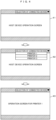
- Fig. 4 is a view illustrating an example of an initial screen of a GUI when operating the other printers.
- Example 1 shows a printer system including two printers (inkjet printers).
- a printer 101 (inkjet printer) and a printer 102 (inkjet printer) includes a device main body 1, a print head 2, a control unit 3, a display operation unit 4, and a cable 5. That is, the printer 101 and the printer 102 are printers having the same configuration.
- the device main body 1 includes a device that supplies ink that is used in printing to the print head 2 and recovers ink that is not used in printing from the print head 2.
- the print head 2 of each printer prints characters set in advance on an object 7 to be printed such as a product that is conveyed by a conveyor line 6.
- the control unit 3 is provided to control the device main body 1 and the print head 2.
- the control unit 3 has a function of operating a printer that is another device from a printer that is a host device as to be described later.
- the display operation unit 4 is a device having an operation function and a display function so that an operator can execute an operation while viewing a GUI screen, and use a touch panel or the like. Note that, an example in which the display operation unit 4 is provided on an upward portion on a front surface of the device main body 1 is illustrated, but a portable device such as a tablet may be used.
- the cable 5 connects between the device main body 1 and the print head 2, and forms a flow passage of ink.
- an electric wire through which a control signal and the like of the control unit 3 is transmitted to the print head 2, and the like also exists inside the cable 5.
- the printer 101 and the printer 102 are connected by a network line 9 such as a cable or a wireless LAN, thereby forming a communication network that enables mutual information communication between the devices.
- a network line 9 such as a cable or a wireless LAN
- FIG. 2 In Fig. 2 , only the printer 101 in Fig. 1 is shown, but the printer 102 also has a similar configuration.
- the printer 101 includes the device main body 1, the print head 2, and the control unit 3.
- a print mechanism part 10 represents an entire mechanism including the device main body 1 and the print head 2. Note that, in Fig. 2 , the display operation unit 4 is omitted.
- the device main body 1 includes an ink tank 11 that stores (accommodates) ink 80, an ink supply pump 12 that supplies the ink 80 to the print head 2, an ink recovery pump 13 that recovers ink collected by the gutter 25 of the print head 2 into the ink tank 11, and a path for ink circulation.
- the print head 2 includes an ink nozzle 21 for making the ink supplied from the device main body 1 into droplets (ink particles).
- the ink nozzle 21 has a piezoelectric element and a periodic excitation voltage is applied to the piezoelectric element. According to this, the ink supplied to the ink nozzle 21 is vibrated, and after the ink is ejected (spouted) from the ink nozzle 21 as an ink column 81, continuous ink droplets are generated. The generated ink droplets travel straight at high speed.
- the print head 2 includes a charging electrode 22, a deflection electrode (including a deflection electrode (positive electrode) 23 and a deflection electrode (negative electrode) 24), and the gutter 25.
- the charging electrode 22 applies a charging voltage corresponding to print contents to the flying ink droplets, thereby charging the ink droplets.
- the deflection electrode causes the charged ink droplets to be deflected in correspondence with a charging amount, and causes the ink droplets 82 to fly toward an object 7 to be printed. As a result, the ink droplets 82 reach and land on the object 7 to be printed. Due to landing of the ink droplets, printing is performed on the object 7 to be printed.
- ink droplets 83 which are not used for printing travel straight without being deflected in the deflection electrode, and are collected (captured) by the gutter 25.
- the ink collected by the gutter 25 is recovered into the ink tank 11 by the ink recovery pump 13.
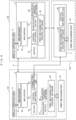
- a configuration of the printer system in Example 1 of the invention will be described with reference to Fig. 3 .
- the printer 101 and the printer 102 are connected to each other by the network line 9, thereby forming a communication network that enables mutual information communication therebetween.
- description will be given of a case where the printer 102 is operated from the printer 101.
- the printer 101 displays a GUI screen on the display operation unit 4 by using an installed web browser 31, and an operator operates the other printer 102 by operating the display operation unit 4 while viewing the screen.
- the web browser 31 installed in the control unit 3 of the printer 101 accesses a web server 32.
- the web server 32 transmits a GUI file 33 to the web browser 31 in response to access from the browser. Examples of the GUI file include an HTML file written in a hyper text markup language (HTML).
- the control software 34 has a special URL, and when the URL is accessed from the web browser 31, the web server 32 transfers the access to the control software 34, and the control software 34 performs processing corresponding to the access.
- a print mechanism part control software 35 is software that controls the print mechanism part 10 of the printer 101 as shown in Fig. 2 .
- the control software 34 communicates with the print mechanism part control software 35 as necessary, and issues a command related to the control of the print mechanism part 10. Note that, the control software 34 and the print mechanism part control software 35 may be implemented in different CPUs. A detailed description of the configuration of the printer 102 will be omitted.
- the printer 101 which is the operating side
- the printer 102 which is an operated side
- the printer 102 is provided with the web server 32, the GUI file 33, the control software 34, and the print mechanism part control software 35.
- the roles of these in the printer 102, which is the operated side, are the same as those described for the printer 101 that is the operating side.
- the printer 102, which is the operated side is also provided with the web browser 31 for displaying the GUI of a host device. Both the printers are connected by the network line 9, and the web browser 31 of the printer 101 can access the web server 32 of the printer 102 that is the operated side.
- the web server 32 of the printer 102 In response to the access from the web browser 31 of the printer 101, the web server 32 of the printer 102, which is the operated side, transmits the GUI file 33 and transfers the access to the control software 34.
- the operating-side printer 101 can access the operated-side printer 102, and the print mechanism part control software 35 of the operated-side printer 102 is activated by an operation command of the display operation unit 4 of the operating-side printer 101, thereby operating the print mechanism part 10 of the printer 102.
- the printer 102 can also drive the printer 101.
- FIG. 4 An example of an initial screen when activating the operated-side printer 102 on the display operation unit 4 of the operating-side printer 101 will be described with reference to Fig. 4 .
- a pull-down menu for selecting a connected device is provided on a screen 41 in Fig. 4 .
- a list of connected devices is displayed as shown on a screen 42.
- the screen is switched to an operation screen for the printer as shown on a screen 43.
- Example 1 it is possible to operate an operated-side printer by a GUI of an operating-side printer.
- the printers 101 and 102 in this example are provided with software having a similar function in the control unit 3, the operating side and the operated side can be switched.
- Example 2 has a basically similar configuration as in Example 1, but a configuration of an operated-side printer 103 is different from the configuration of the printer 102 of Example 1.
- the operated-side printer 103 in Example 2 is a simplified printer that is provided with the print mechanism part control software 35 but is not provided with the other configurations.
- the simplified printer 103 is not provided with a GUI file or control software, and is not capable of operating independently.
- the operation of this printer 103 is performed by the operating-side printer 101 via a network.
- the web browser 31 executes an access to the URL associated with the printer 103 (simplified printer) with respect to the web server 32.
- the web server 32 detects that the printer 103 is accessed based on the URL, and makes a request for the GUI duplication unit 36 to duplicate the GUI file and the control software.
- the GUI duplication unit 36 duplicates the GUI file 33 for operating a host device and the control software 34 for controlling the host device, and constructs (creates) a duplicated GUI file 37 for operating the printer 103 and the duplicated control software 38 for controlling the printer 103.
- the web server 32 transmits the duplicated GUI file 37 and transfers access to the duplicated control software 38 in response to the access from the web browser 31.
- the duplicated control software 38 accesses the print mechanism part control software 35 installed in the printer 103 via the network line 9 as necessary. According to this, the print mechanism part control software 35 of the printer 103 drives the print mechanism part 10 and executes (operates) the printing operation.
- the operating-side printer can execute not only an operation of a host device but also an operation of the simplified printer.
- the simplified printer can be made inexpensive since the functions of the operating-side printer are not provided, and thus a reduction in the cost of the entire printer system is realized.
- Example 3 illustrates a system in which the printer 101 as an operating-side printer operates the printer 103 in a case where the simplified printer 103 as shown in Example 2 is already being operated by the other printer 102. In other words, this is a case where the printer 101 is switched to operate the simplified printer 103 that is already being operated by another device.
- the switching of operation is performed as follows. Note that, each component within the printer has already been described, and thus description thereof will be omitted here.
- the web browser 31 of the printer 101 executes an access to the printer 103 with respect to the web server 32.
- the web server 32 makes a request for a connection confirmation unit 39 to confirm information of a connection destination indicated by URL.
- the connection confirmation unit 39 makes a request for the print mechanism part control software 35 of the printer 103 to transmit device information.
- the print mechanism part control software 35 retains a control information file 40 and provides information based on the control information file 40.
- the control information file 40 retains a true/false value as to whether a host device is controlled by another device and URL information of the another device that controls the host device in a case where the host device is controlled.
- the control information file 40 retains true for the true/false value as to whether the printer is controlled and a URL of the printer 102 as a URL of the another device. Since the printer 102 operates the printer 103, the printer 102 retains the duplicated GUI file 37 and the duplicated control software 38, which are copies of the host device, with respect to the printer 103, as described in Example 2.
- the connection confirmation unit 39 of the printer 101 transmits the URL of the printer 102, which is a connection destination, to the web server 32 on the basis of the information acquired from the print mechanism part control software 35 of the printer 103.
- the web server 32 transfers the access of the web browser 31 to the web server 32 of the printer 102 on the basis of the acquired URL.
- the web server 32 of the printer 102 transmits the duplicated GUI file 37 and the duplicated control software 38 for operating the printer 103, which has been used to operate the printer 103, to the printer 101.
- the printer 101 retains the duplicated GUI file 37 and the duplicated control software 38.
- the printer 101 can execute the operation of the printer 103.
- the printer 101 may generate the duplicated GUI file 37 and the duplicated control software 38 as in Example 2.
- Example 3 of the invention even in a case where the other printer is already operating a simplified printer, a host printer can execute an operation of the simplified printer.
- Example 4 of the invention will be described with reference to Fig. 7 and Fig. 8 .
- Fig. 7 is a view illustrating a configuration of a printer system in Example 4.
- Fig. 8 is a view illustrating a flow of connected device confirmation in Example 4.
- Example 4 the difference when accessing an operated-side printer is absorbed, and it is possible to access the other printer without being aware of the difference on an operator side.
- description will be made on the assumption that an operating-side printer is printer 101.
- the web browser 31 of the printer 101 issues an access to a URL of a desired operated-side device with respect to the web server 32.
- the web server 32 issues a connection confirmation request to the connection confirmation unit 39.
- the connection confirmation unit 39 performs a connected device confirmation for a URL of an access destination.
- connection confirmation S81 A flow of the connection confirmation is shown in Fig. 8 .
- a connected device confirmation is performed in connected device confirmation S81.
- connection destination information of GUI is acquired from the web server 32 of the printer 105 in GUI connection information acquisition S82.
- control information is confirmed in control information confirmation S83.
- true/false value data as to whether or not a printer is being controlled is false in the control information file 40 acquired from the print mechanism part control software 35 of the printer 104, and it can be seen that the simplified printer is not being controlled by the other device.
- a GUI duplication request is issued to the GUI duplication unit 36 of the printer 101 in control duplication 84.
- the GUI duplication unit 36 of the printer 101 duplicates the GUI file 33 and the control software 34 of the host device, and creates the duplicated GUI file 37 and the duplicated control software 38.
- the connection confirmation unit 39 of the printer 101 transmits the URI of the duplicated GUI file 37 to the web server 32 of the printer 105.
- the connection destination is the simplified printer 103 that is being controlled by the other printer 102
- the true/false value data as to whether or not a printer is being controlled is true in the control information file 40 acquired from the print mechanism part control software 35, and it can be seen that the printer is being controlled by the other device (printer 102).
- a value of a URL of the duplicated GUI file 37 of the printer 102 that is being controlled is acquired from the control information file 40 of the printer 103 in control device information acquisition S85, and is transmitted to the web server 32 of the printer 101.
- the web server 32 of the printer 101 is finally able to acquire the URL of the GUI, and can display the GUI on the display operation unit 4 of the printer 101 in GUI display S86.
- This method allows an operator to perform an operation without being aware of the difference between a device to be connected and an operating-side printer.
- An example of a GUI for the operator in this case is as shown in Fig. 4 . That is, the initial screen 41 in Fig. 4 is provided with a pull-down menu for selecting a device to be connected. A device list of a printer to be operated is displayed in the pull-down menu as shown on the screen 42. When the desired printer is selected from the device list, the screen switches to an operation screen for the printer as shown on the screen 43. On the screen, each printer shown in the pull-down menu may be the same device as the operating printer or may be a simplified printer, but the operator does not need to be aware of the difference.
- Example 4 of the invention an operator can smoothly operate a printer to be connected (operated) without being aware of whether the printer to be connected (operated) is a normal printer or a simplified printer.
- Fig. 9 is a view illustrating a configuration of a printer system according to Example 5 of the invention.
- Example 5 enables an operating-side printer to display the GUI even in a case where the GUI exists on a different network. That is, as in the example described in Example 3 ( Fig. 6 ), in a case of accessing the simplified printer 103 that is being controlled by the other printer 102, the other printer 102 may exist on a different network, and thus the printer 102 may not be directly accessed from a host device (printer 101). Even in such a case, a configuration in which connection is possible is shown in Fig. 9 . Even in this example, description will be made on the assumption that the operating-side printer that operates the other printer is the printer 101.
- Example 5 illustrated in Fig. 9 in a case where the printer 102 is operating the simplified printer 103, the printer 101 switches to operate the simplified printer 103.
- the host printer (printer 101) and the other printer 102 exist on different networks, the operating-side printer 101 cannot directly access the other printer 102.
- the operation switching is performed as follows.
- the web browser 31 of the printer 101 accesses the web server 32, and the web server 32 makes a request for the connection confirmation unit 39 to confirm connection.
- the connection confirmation unit 39 accesses the print mechanism part control software 35 of the printer 103.
- the control information file 40 of the printer 103 stores a URL of a router 50 provided in the host device instead of a URL of the printer 102.
- the connection confirmation unit 39 of the printer 101 receives the URL from the printer 103 and transmits the URL to the web server 32.
- the web server 32 that has received the URL accesses the router 50 of the printer 103.
- the router 50 knows the URL of the web server 32 of the printer 102 that controls the host device, and transfers the access transmitted thereto. According to this, the web server 32 of the printer 101 can access the web server 32 of another network via the router 50.
- the printer 101 can obtain the duplicated GUI file 37 and the duplicated control software 38 of the printer 102 that exists on a network different from that of the printer 101 via the router 50. Then, the printer 101 can operate the printer 103 by using the duplicated GUI file 37 and the duplicated control software 38 which are obtained.
- Example 5 of the invention described above it is possible to obtain the duplicated GUI file 37 and the duplicated control software 38 of a printer connected to another network, and to control a printer that is operated by a host device.
- Fig. 10 is a view illustrating a configuration of a printer system in Example 6 of the invention.
- Example 6 has a basically similar configuration as in Example 4 (the printer system illustrated in Fig. 7 ), and the basic operation is similar as in Example 4.
- Example 6 is different from Example 4 in that a connected device operated by the printer 101 is not a printer, but print inspection devices 201 and 202 installed as a part of the printer system.
- the print inspection devices 201 and 202 are provided to set print information and inspect whether a printed state is normal or not.
- description will be made on the assumption that the print inspection devices 201 and 202 have a similar software configuration as in the simplified printer.
- the printer 101 includes a web server 32, a host device GUI file 33, and the control software 34. A method of displaying the GUI is similar as in Example 1, and thus description thereof will be omitted here.
- Example 6 information of an information providing unit 45 of the printer 101 that is a host device is provided to the print inspection devices 201 and 202 which are devices to be connected by the connection confirmation unit 39.
- This configuration is used, for example, to provide character information that is being currently printed to the print inspection devices 201 and 202 so as to eliminate the need to set print information for inspection in the print inspection devices 201 and 202.
- a device that is a connection destination print inspection device 201 or 202
- the information providing unit 45 changes the provided information in correspondence with the connection destination information from the connection confirmation unit 39.
- Example 6 of the invention described above it is possible to operate a device to be connected other than a printer (in this example, the print inspection device) from the printer 101 in a similar manner as in the operation of other printers.
Landscapes
- Engineering & Computer Science (AREA)
- Theoretical Computer Science (AREA)
- Human Computer Interaction (AREA)
- Physics & Mathematics (AREA)
- General Engineering & Computer Science (AREA)
- General Physics & Mathematics (AREA)
- Accessory Devices And Overall Control Thereof (AREA)
- User Interface Of Digital Computer (AREA)
Abstract
Description
- The present invention relates to a printer system and a control method for a printer system.
- An industrial printer (for example, an inkjet printer) is used as a printer that prints a product name, a manufacturing date, an expiration date, and the like on a manufactured product and the like (an object to be printed). In general, an operator of the industrial printer inputs information or data such as print contents to a control unit from a display operation unit (for example, a touch panel) attached to a main body, and then operates the printer to perform a printing operation while referring to images displayed on a screen of the display operation unit and giving an instruction for an image for performing a desired operation through an operation with a finger or the like. That is, the operator inputs an operation command to the printer through a so-called graphical user interface (GUI), and the printer executes a printing operation according to the operation command. When a plurality of production lines are installed, a plurality of printers are installed in many cases, and a plurality of operators are required to operate the printers.
- By the way, although not related to a printer,
WO2013/014874 (Patent Document 1) introduces a technology that specifies a plurality of devices and draws (displays on a screen) a GUI corresponding to the devices in order to facilitate a linked operation of the plurality of devices. That is,Patent Document 1 describes a "configuration including a device information management unit that acquires device information that specifies first and second devices connected to a network, a device linkage service information management unit that acquires linkage information that specifies a linked operation realized by a first function provided in the first device and a second function provided in the second device, and a GUI generation and drawing unit that associates and draws first and second GUI parts that indicate the first and second devices specified by the device information, and a third GUI part that indicates the linked operation specified by the linkage information". - Patent Document 1:
WO2013/014874 - As described above, when a plurality of printers are installed on a production line, many people are required to operate the plurality of printers at the same time. However, this is not easy. Therefore, when a plurality of printers are installed, there is a demand for one operator to be able to operate the other printers from one of the printers. If it is possible to operate the plurality of printers from one printer, since one operator can perform an operation (printing operation with the printers) without moving to installation positions of the other printers, it is possible to operate the printers efficiently with a small number of people.
- Here, an object of the invention is to provide a printer system and a control method for a printer system which makes it easy to operate other printers from one printer in a printer system including a plurality of printers.
- To accomplish the object, according to an aspect of the invention, there is provided a printer system including a plurality of printers provided with a print mechanism part control software that controls a printing operation unit by a GUI displayed on a display operation unit, the plurality of printers being connected to a network. At least one printer among the plurality of printers is an operating-side printer that operates the other printers. The operating-side printer is provided with a GUI file for a host device, and control software that gives a command to the print mechanism part control software. The operating-side printer constructs a GUI file and control software for operating an operated-side printer. The operated-side printer is operated on the basis of the constructed GUI file and control software of the operated-side printer.
- In addition, according to another aspect of the invention, there is provided a control method for a printer system including a plurality of printers provided with a print mechanism part control software that controls a printing operation unit by a GUI displayed on a display operation unit, the plurality of printers being connected to a network. An operating-side printer that operates another printer is provided with a GUI file for a host device, and control software that gives a command to the print mechanism part control software. A GUI file and control software for operating an operated-side printer are constructed. The operated-side printer is operated on the basis of the constructed GUI file and control software of the operated-side printer.
- According to the invention, in a print system including a plurality of printers, it is possible to provide a printer system and a control method for a printer system which are capable of simply operating other printers from one printer.
-
-
Fig. 1 is a view illustrating an external appearance of a printer system in Example 1 of the invention. -
Fig. 2 is a view illustrating a printing operation of an inkjet printer. -
Fig. 3 is a view illustrating a configuration of the printer system in Example 1 of the invention. -
Fig. 4 is a view illustrating an example of an initial screen of a GUI when operating other printers. -
Fig. 5 is a view illustrating a configuration of a printer system in Example 2 of the invention. -
Fig. 6 is a view illustrating a configuration of a printer system in Example 3. -
Fig. 7 is a view illustrating a configuration of a printer system in Example 4. -
Fig. 8 is a view illustrating a flow of connected device confirmation in Example 4. -
Fig. 9 is a view illustrating a configuration of a printer system in Example 5 of the invention. -
Fig. 10 is a view illustrating a configuration of a printer system in Example 6. - Hereinafter, examples of the invention will be described in detail with reference to the accompanying drawings. Note that, the invention should not be construed as being limited to description of the following examples. That is, it is easily understood by those skilled in the art that the configuration can be changed without departing from the technical idea or gist of the invention. For example, the invention can be realized not only in a printer system using an inkjet printer, but also in a printer system using other printers.
- In addition, in configurations of the following examples, the same reference numeral will be given to portions having the same or similar function, and redundant description will be omitted.
- In addition, in order to facilitate understanding of the invention, a position, a size, a shape, a range, and the like of respective configurations shown in the drawings do not represent a position, a size, a shape, a range, and the like of device configurations in an actual product. Therefore, the invention is not limited to the position, the size, the shape, the range, and the like of the device components disclosed in the drawings.
- Hereinafter, Example 1 of the invention will be described with reference to
Fig. 1 to Fig. 4 . Note that, in this example, description will be given with reference to an inkjet printer that is often used as an industrial printer as an example. Note that, in the following description, the inkjet printer may be simply referred to as a printer.Fig. 1 is a view illustrating an external appearance of a printer system in Example 1 of the invention.Fig. 2 is a view illustrating a printing operation of the inkjet printer.Fig. 3 is a view illustrating a configuration of the printer system in Example 1 of the invention.Fig. 4 is a view illustrating an example of an initial screen of a GUI when operating the other printers. - First, an overall configuration of the printer system in Example 1 will be described with reference to
Fig. 1 . InFig. 1 , Example 1 shows a printer system including two printers (inkjet printers). Each of a printer 101 (inkjet printer) and a printer 102 (inkjet printer) includes a devicemain body 1, aprint head 2, acontrol unit 3, adisplay operation unit 4, and acable 5. That is, theprinter 101 and theprinter 102 are printers having the same configuration. - The device
main body 1 includes a device that supplies ink that is used in printing to theprint head 2 and recovers ink that is not used in printing from theprint head 2. Theprint head 2 of each printer prints characters set in advance on anobject 7 to be printed such as a product that is conveyed by aconveyor line 6. - The
control unit 3 is provided to control the devicemain body 1 and theprint head 2. In Example 1, thecontrol unit 3 has a function of operating a printer that is another device from a printer that is a host device as to be described later. - The
display operation unit 4 is a device having an operation function and a display function so that an operator can execute an operation while viewing a GUI screen, and use a touch panel or the like. Note that, an example in which thedisplay operation unit 4 is provided on an upward portion on a front surface of the devicemain body 1 is illustrated, but a portable device such as a tablet may be used. - The
cable 5 connects between the devicemain body 1 and theprint head 2, and forms a flow passage of ink. In addition, an electric wire through which a control signal and the like of thecontrol unit 3 is transmitted to theprint head 2, and the like also exists inside thecable 5. - In addition, the
printer 101 and theprinter 102 are connected by anetwork line 9 such as a cable or a wireless LAN, thereby forming a communication network that enables mutual information communication between the devices. - Here, in respective drawings used in description of examples, different reference numerals (numbers) are given to clarify that a plurality of printers are provided, but constituent devices in the respective printers may have a similar configuration. Therefore, with regard to configurations in the printers illustrated in the respective drawings, the same reference numeral (number) is used for the same constituent element (a device, software, or the like). Therefore, redundant description of a constituent element that has already been described is basically omitted. This is also true of other examples to be described below.
- Next, an overview of a printing operation of the inkjet printer in Example 1 will be described with reference to
Fig. 2 . InFig. 2 , only theprinter 101 inFig. 1 is shown, but theprinter 102 also has a similar configuration. InFig. 2 , theprinter 101 includes the devicemain body 1, theprint head 2, and thecontrol unit 3. Aprint mechanism part 10 represents an entire mechanism including the devicemain body 1 and theprint head 2. Note that, inFig. 2 , thedisplay operation unit 4 is omitted. - First, the device
main body 1 includes anink tank 11 that stores (accommodates)ink 80, anink supply pump 12 that supplies theink 80 to theprint head 2, anink recovery pump 13 that recovers ink collected by thegutter 25 of theprint head 2 into theink tank 11, and a path for ink circulation. - The
print head 2 includes anink nozzle 21 for making the ink supplied from the devicemain body 1 into droplets (ink particles). Theink nozzle 21 has a piezoelectric element and a periodic excitation voltage is applied to the piezoelectric element. According to this, the ink supplied to theink nozzle 21 is vibrated, and after the ink is ejected (spouted) from theink nozzle 21 as anink column 81, continuous ink droplets are generated. The generated ink droplets travel straight at high speed. - Furthermore, the
print head 2 includes a chargingelectrode 22, a deflection electrode (including a deflection electrode (positive electrode) 23 and a deflection electrode (negative electrode) 24), and thegutter 25. The chargingelectrode 22 applies a charging voltage corresponding to print contents to the flying ink droplets, thereby charging the ink droplets. The deflection electrode causes the charged ink droplets to be deflected in correspondence with a charging amount, and causes theink droplets 82 to fly toward anobject 7 to be printed. As a result, theink droplets 82 reach and land on theobject 7 to be printed. Due to landing of the ink droplets, printing is performed on theobject 7 to be printed. On the other hand,ink droplets 83 which are not used for printing (ink droplets not charged by the charging electrode 22) travel straight without being deflected in the deflection electrode, and are collected (captured) by thegutter 25. The ink collected by thegutter 25 is recovered into theink tank 11 by theink recovery pump 13. - Next, a configuration of the printer system in Example 1 of the invention will be described with reference to
Fig. 3 . InFig. 3 , theprinter 101 and theprinter 102 are connected to each other by thenetwork line 9, thereby forming a communication network that enables mutual information communication therebetween. Here, description will be given of a case where theprinter 102 is operated from theprinter 101. - The
printer 101 displays a GUI screen on thedisplay operation unit 4 by using an installedweb browser 31, and an operator operates theother printer 102 by operating thedisplay operation unit 4 while viewing the screen. Theweb browser 31 installed in thecontrol unit 3 of theprinter 101 accesses aweb server 32. Theweb server 32 transmits aGUI file 33 to theweb browser 31 in response to access from the browser. Examples of the GUI file include an HTML file written in a hyper text markup language (HTML). In addition, thecontrol software 34 has a special URL, and when the URL is accessed from theweb browser 31, theweb server 32 transfers the access to thecontrol software 34, and thecontrol software 34 performs processing corresponding to the access. A print mechanismpart control software 35 is software that controls theprint mechanism part 10 of theprinter 101 as shown inFig. 2 . Thecontrol software 34 communicates with the print mechanismpart control software 35 as necessary, and issues a command related to the control of theprint mechanism part 10. Note that, thecontrol software 34 and the print mechanismpart control software 35 may be implemented in different CPUs. A detailed description of the configuration of theprinter 102 will be omitted. - Next, the operation of the
printer 102 from theprinter 101 will be described. Theprinter 101, which is the operating side, is provided with thesame web browser 31 that displays the GUI for operating a host device. Theprinter 102, which is an operated side, is provided with theweb server 32, theGUI file 33, thecontrol software 34, and the print mechanismpart control software 35. The roles of these in theprinter 102, which is the operated side, are the same as those described for theprinter 101 that is the operating side. Theprinter 102, which is the operated side, is also provided with theweb browser 31 for displaying the GUI of a host device. Both the printers are connected by thenetwork line 9, and theweb browser 31 of theprinter 101 can access theweb server 32 of theprinter 102 that is the operated side. In response to the access from theweb browser 31 of theprinter 101, theweb server 32 of theprinter 102, which is the operated side, transmits theGUI file 33 and transfers the access to thecontrol software 34. - By transmitting and receiving information between the operating-side printer and the operated-side printer in this manner, the operating-
side printer 101 can access the operated-side printer 102, and the print mechanismpart control software 35 of the operated-side printer 102 is activated by an operation command of thedisplay operation unit 4 of the operating-side printer 101, thereby operating theprint mechanism part 10 of theprinter 102. Note that, in Example 1, description has been given of a case where theprinter 102 is operated from theprinter 101, but theprinter 102 can also drive theprinter 101. In addition, although description has been given of a case where one printer operates another one printer, there is no problem although two or more operated-side printers exist. - Next, an example of an initial screen when activating the operated-
side printer 102 on thedisplay operation unit 4 of the operating-side printer 101 will be described with reference toFig. 4 . A pull-down menu for selecting a connected device is provided on ascreen 41 inFig. 4 . When this is selected, a list of connected devices is displayed as shown on ascreen 42. When a desired printer (operated-side printer) to be switched is selected from this device list, the screen is switched to an operation screen for the printer as shown on ascreen 43. - According to Example 1 described above, it is possible to operate an operated-side printer by a GUI of an operating-side printer. In addition, since the
printers control unit 3, the operating side and the operated side can be switched. - Next, Example 2 of the invention will be described with reference to
Fig. 5 . Example 2 has a basically similar configuration as in Example 1, but a configuration of an operated-side printer 103 is different from the configuration of theprinter 102 of Example 1. Specifically, the operated-side printer 103 in Example 2 is a simplified printer that is provided with the print mechanismpart control software 35 but is not provided with the other configurations. In other words, thesimplified printer 103 is not provided with a GUI file or control software, and is not capable of operating independently. The operation of thisprinter 103 is performed by the operating-side printer 101 via a network. - As illustrated in
Fig. 5 , in theprinter 101 that is an operating-side printer, theweb browser 31 executes an access to the URL associated with the printer 103 (simplified printer) with respect to theweb server 32. Theweb server 32 detects that theprinter 103 is accessed based on the URL, and makes a request for theGUI duplication unit 36 to duplicate the GUI file and the control software. TheGUI duplication unit 36 duplicates theGUI file 33 for operating a host device and thecontrol software 34 for controlling the host device, and constructs (creates) a duplicatedGUI file 37 for operating theprinter 103 and the duplicatedcontrol software 38 for controlling theprinter 103. Theweb server 32 transmits the duplicatedGUI file 37 and transfers access to the duplicatedcontrol software 38 in response to the access from theweb browser 31. The duplicatedcontrol software 38 accesses the print mechanismpart control software 35 installed in theprinter 103 via thenetwork line 9 as necessary. According to this, the print mechanismpart control software 35 of theprinter 103 drives theprint mechanism part 10 and executes (operates) the printing operation. - According to Example 2 of the invention, the operating-side printer can execute not only an operation of a host device but also an operation of the simplified printer. In this case, the simplified printer can be made inexpensive since the functions of the operating-side printer are not provided, and thus a reduction in the cost of the entire printer system is realized.
- Next, a printer system according to Example 3 of the invention will be described with reference to
Fig. 6 . Example 3 illustrates a system in which theprinter 101 as an operating-side printer operates theprinter 103 in a case where thesimplified printer 103 as shown in Example 2 is already being operated by theother printer 102. In other words, this is a case where theprinter 101 is switched to operate thesimplified printer 103 that is already being operated by another device. The switching of operation is performed as follows. Note that, each component within the printer has already been described, and thus description thereof will be omitted here. - First, the
web browser 31 of theprinter 101 executes an access to theprinter 103 with respect to theweb server 32. Theweb server 32 makes a request for aconnection confirmation unit 39 to confirm information of a connection destination indicated by URL. According to this, theconnection confirmation unit 39 makes a request for the print mechanismpart control software 35 of theprinter 103 to transmit device information. The print mechanismpart control software 35 retains acontrol information file 40 and provides information based on thecontrol information file 40. Thecontrol information file 40 retains a true/false value as to whether a host device is controlled by another device and URL information of the another device that controls the host device in a case where the host device is controlled. In this case, since theprinter 103 is controlled from theother printer 102, thecontrol information file 40 retains true for the true/false value as to whether the printer is controlled and a URL of theprinter 102 as a URL of the another device. Since theprinter 102 operates theprinter 103, theprinter 102 retains the duplicatedGUI file 37 and the duplicatedcontrol software 38, which are copies of the host device, with respect to theprinter 103, as described in Example 2. Here, theconnection confirmation unit 39 of theprinter 101 transmits the URL of theprinter 102, which is a connection destination, to theweb server 32 on the basis of the information acquired from the print mechanismpart control software 35 of theprinter 103. Theweb server 32 transfers the access of theweb browser 31 to theweb server 32 of theprinter 102 on the basis of the acquired URL. In response to the access, theweb server 32 of theprinter 102 transmits the duplicatedGUI file 37 and the duplicatedcontrol software 38 for operating theprinter 103, which has been used to operate theprinter 103, to theprinter 101. According to this, theprinter 101 retains the duplicatedGUI file 37 and the duplicatedcontrol software 38. As a result, theprinter 101 can execute the operation of theprinter 103. Note that, in this case, instead of the case where theprinter 101 is provided with the duplicatedGUI file 37 and the duplicatedcontrol software 38 from theprinter 102, theprinter 101 may generate the duplicatedGUI file 37 and the duplicatedcontrol software 38 as in Example 2. - According to Example 3 of the invention, even in a case where the other printer is already operating a simplified printer, a host printer can execute an operation of the simplified printer.
- Next, Example 4 of the invention will be described with reference to
Fig. 7 andFig. 8 .Fig. 7 is a view illustrating a configuration of a printer system in Example 4.Fig. 8 is a view illustrating a flow of connected device confirmation in Example 4. - As is clear from the above-described examples, there are a number of cases where a printer accesses another printer to perform an operation, and there is a difference depending on a printer to be accessed and a state of the printer. In Example 4, the difference when accessing an operated-side printer is absorbed, and it is possible to access the other printer without being aware of the difference on an operator side. In the example illustrated in
Fig. 7 , description will be made on the assumption that an operating-side printer isprinter 101. - The
web browser 31 of theprinter 101 issues an access to a URL of a desired operated-side device with respect to theweb server 32. In a case where an object to be accessed is an external device, theweb server 32 issues a connection confirmation request to theconnection confirmation unit 39. Theconnection confirmation unit 39 performs a connected device confirmation for a URL of an access destination. - A flow of the connection confirmation is shown in
Fig. 8 . First, a connected device confirmation is performed in connected device confirmation S81. In a case where a connection destination is theprinter 105, connection destination information of GUI is acquired from theweb server 32 of theprinter 105 in GUI connection information acquisition S82. In a case where the connection destination is a simplified printer, control information is confirmed in control information confirmation S83. In a case where the connection destination is asimplified printer 104 that is not being operated by the other device, true/false value data as to whether or not a printer is being controlled is false in thecontrol information file 40 acquired from the print mechanismpart control software 35 of theprinter 104, and it can be seen that the simplified printer is not being controlled by the other device. In this case, a GUI duplication request is issued to theGUI duplication unit 36 of theprinter 101 in control duplication 84. - According to this, the
GUI duplication unit 36 of theprinter 101 duplicates theGUI file 33 and thecontrol software 34 of the host device, and creates the duplicatedGUI file 37 and the duplicatedcontrol software 38. - The
connection confirmation unit 39 of theprinter 101 transmits the URI of the duplicatedGUI file 37 to theweb server 32 of theprinter 105. In a case where the connection destination is thesimplified printer 103 that is being controlled by theother printer 102, the true/false value data as to whether or not a printer is being controlled is true in thecontrol information file 40 acquired from the print mechanismpart control software 35, and it can be seen that the printer is being controlled by the other device (printer 102). A value of a URL of the duplicatedGUI file 37 of theprinter 102 that is being controlled is acquired from thecontrol information file 40 of theprinter 103 in control device information acquisition S85, and is transmitted to theweb server 32 of theprinter 101. In any case, theweb server 32 of theprinter 101 is finally able to acquire the URL of the GUI, and can display the GUI on thedisplay operation unit 4 of theprinter 101 in GUI display S86. - This method allows an operator to perform an operation without being aware of the difference between a device to be connected and an operating-side printer. An example of a GUI for the operator in this case is as shown in
Fig. 4 . That is, theinitial screen 41 inFig. 4 is provided with a pull-down menu for selecting a device to be connected. A device list of a printer to be operated is displayed in the pull-down menu as shown on thescreen 42. When the desired printer is selected from the device list, the screen switches to an operation screen for the printer as shown on thescreen 43. On the screen, each printer shown in the pull-down menu may be the same device as the operating printer or may be a simplified printer, but the operator does not need to be aware of the difference. - As described above, according to Example 4 of the invention, an operator can smoothly operate a printer to be connected (operated) without being aware of whether the printer to be connected (operated) is a normal printer or a simplified printer.
- Next, Example 5 of the invention will be described with reference to
Fig. 9. Fig. 9 is a view illustrating a configuration of a printer system according to Example 5 of the invention. - Example 5 enables an operating-side printer to display the GUI even in a case where the GUI exists on a different network. That is, as in the example described in Example 3 (
Fig. 6 ), in a case of accessing thesimplified printer 103 that is being controlled by theother printer 102, theother printer 102 may exist on a different network, and thus theprinter 102 may not be directly accessed from a host device (printer 101). Even in such a case, a configuration in which connection is possible is shown inFig. 9 . Even in this example, description will be made on the assumption that the operating-side printer that operates the other printer is theprinter 101. - As in Example 3 illustrated in
Fig. 6 , in Example 5 illustrated inFig. 9 , in a case where theprinter 102 is operating thesimplified printer 103, theprinter 101 switches to operate thesimplified printer 103. In Example 5, since the host printer (printer 101) and theother printer 102 exist on different networks, the operating-side printer 101 cannot directly access theother printer 102. - In this case, the operation switching is performed as follows. First, the
web browser 31 of theprinter 101 accesses theweb server 32, and theweb server 32 makes a request for theconnection confirmation unit 39 to confirm connection. Theconnection confirmation unit 39 accesses the print mechanismpart control software 35 of theprinter 103. In this case, thecontrol information file 40 of theprinter 103 stores a URL of arouter 50 provided in the host device instead of a URL of theprinter 102. Theconnection confirmation unit 39 of theprinter 101 receives the URL from theprinter 103 and transmits the URL to theweb server 32. Theweb server 32 that has received the URL accesses therouter 50 of theprinter 103. Therouter 50 knows the URL of theweb server 32 of theprinter 102 that controls the host device, and transfers the access transmitted thereto. According to this, theweb server 32 of theprinter 101 can access theweb server 32 of another network via therouter 50. - In this way, the
printer 101 can obtain the duplicatedGUI file 37 and the duplicatedcontrol software 38 of theprinter 102 that exists on a network different from that of theprinter 101 via therouter 50. Then, theprinter 101 can operate theprinter 103 by using the duplicatedGUI file 37 and the duplicatedcontrol software 38 which are obtained. - According to Example 5 of the invention described above, it is possible to obtain the duplicated
GUI file 37 and the duplicatedcontrol software 38 of a printer connected to another network, and to control a printer that is operated by a host device. - Next, Example 6 of the invention will be described with reference to
Fig. 10. Fig. 10 is a view illustrating a configuration of a printer system in Example 6 of the invention. Example 6 has a basically similar configuration as in Example 4 (the printer system illustrated inFig. 7 ), and the basic operation is similar as in Example 4. - Example 6 is different from Example 4 in that a connected device operated by the
printer 101 is not a printer, butprint inspection devices print inspection devices print inspection devices printer 101 includes aweb server 32, a hostdevice GUI file 33, and thecontrol software 34. A method of displaying the GUI is similar as in Example 1, and thus description thereof will be omitted here. - In Example 6, information of an
information providing unit 45 of theprinter 101 that is a host device is provided to theprint inspection devices connection confirmation unit 39. - This configuration is used, for example, to provide character information that is being currently printed to the
print inspection devices print inspection devices print inspection device 201 or 202), in a case where theprint inspection device 201 is being operated by theother printer 102, it is assumed that the print information for inspection has already been provided from theother printer 102, and thus no information is provided. In this way, theinformation providing unit 45 changes the provided information in correspondence with the connection destination information from theconnection confirmation unit 39. - According to Example 6 of the invention described above, it is possible to operate a device to be connected other than a printer (in this example, the print inspection device) from the
printer 101 in a similar manner as in the operation of other printers. -
- 1
- Device main body
- 2
- Print head
- 3
- Control unit
- 4
- Display operation unit
- 5
- Cable
- 6
- Conveyor line
- 7
- Object to be printed
- 9
- Network line
- 10
- Print mechanism part
- 11
- Ink tank
- 12
- Pump
- 13
- Pump
- 21
- Ink nozzle
- 22
- Charging electrode
- 23
- Deflection electrode (positive electrode)
- 24
- Deflection electrode (negative electrode)
- 25
- Gutter
- 31
- Web browser
- 32
- Web server
- 33
- GUI file
- 34
- Control software
- 35
- Print mechanism part control software
- 36
- GUI duplication unit
- 37
- Duplicated GUI file
- 38
- Duplicated control software
- 39
- Connection confirmation unit
- 40
- Control information file
- 45
- Information providing unit
- 80
- Ink
- 81
- Ink column
- 82
- Ink droplets
- 83
- Ink droplets
- 101
- Printer
- 102
- Printer
- 103
- Printer
- 104
- Printer
- 105
- Printer
- 201
- Print inspection device
- 202
- Print inspection device
Claims (14)
- A printer system comprising:a plurality of printers provided with a print mechanism part control software that controls a printing operation unit by a GUI displayed on a display operation unit, the plurality of printers being connected to a network,wherein at least one printer among the plurality of printers is an operating-side printer that operates the other printers,the operating-side printer is provided with a GUI file for a host device, and control software that gives a command to the print mechanism part control software,the operating-side printer constructs a GUI file and control software for operating an operated-side printer, andthe operated-side printer is operated on the basis of the constructed GUI file and the control software of the operated-side printer.
- The printer system according to claim 1,
wherein in a case where the operated-side printer is provided with the GUI file and the control software, the GUI file and the control software which are constructed by the operating-side printer to operate the operated-side printer are constructed by taking in the GUI file and the control software of the operated-side printer via the network. - The printer system according to claim 1,
wherein in a case where the operated-side printer is not provided with the GUI file and the control software and is not operated by the other printer, the GUI file and the control software which are constructed by the operating-side printer to operate the operated-side printer are constructed by duplicating the GUI file and the control software of the operating-side printer. - The printer system according to claim 1,
wherein in a case where the operated-side printer is not provided with the GUI file and the control software and is operated by another printer, the GUI file and the control software which are constructed by the operating-side printer to operate the operated-side printer are constructed by acquiring the GUI file and the control software of the operated-side printer which are provided in the another printer. - The printer system according to claim 1,wherein the operated-side printer is a simplified printer provided with only the print mechanism part control software, andin a case where the simplified printer is not operated by another printer, the operating-side printer duplicates the GUI file of the host device to duplicate a GUI file for the simplified printer, and operates the simplified printer by using the duplicated GUI file.
- The printer system according to claim 1,
wherein the operated-side printer has a function of transmitting whether or not the operated-side printer has already been operated by the other printer to the operating-side printer through access from the operating-side printer. - The printer system according to claim 1, further comprising:a print inspection device configured to inspect a printed state,wherein the operating-side printer duplicates the GUI file and the control software of the host device to construct a GUI file and control software for operating the print inspection device, andthe print inspection device is operated by using the constructed GUI file and the control software.
- A control method for a printer system including a plurality of printers provided with a print mechanism part control software that controls a printing operation unit by a GUI displayed on a display operation unit, the plurality of printers being connected to a network,wherein an operating-side printer that operates another printer is provided with a GUI file for a host device, and control software that gives a command to the print mechanism part control software,a GUI file and control software for operating an operated-side printer are constructed, andthe operated-side printer is operated on the basis of the constructed GUI file and the control software of the operated-side printer.
- The control method for a printer system according to claim 8,
wherein in a case where the operated-side printer is provided with the GUI file and the control software, the GUI file and the control software which are constructed by the operating-side printer to operate the operated-side printer are constructed by taking in the GUI file and the control software of the operated-side printer via the network. - The control method for a printer system according to claim 8,
wherein in a case where the operated-side printer is not provided with the GUI file and the control software and is not operated by the other printer, the GUI file and the control software which are constructed by the operating-side printer to operate the operated-side printer are constructed by duplicating the GUI file and the control software of the operating-side printer. - The control method for a printer system according to claim 8,
wherein in a case where the operated-side printer is not provided with the GUI file and the control software and is operated by another printer, the GUI file and the control software which are constructed by the operating-side printer to operate the operated-side printer are constructed by acquiring the GUI file and the control software of the operated-side printer which are provided in the another printer. - The control method for a printer system according to claim 8,wherein a simplified printer provided with only the print mechanism part control software is disposed as the operated-side printer, andin a case where the simplified printer is not operated by another printer, the operating-side printer duplicates the GUI file of the host device to duplicate a GUI file for the simplified printer, and operates the simplified printer by using the duplicated GUI file.
- The control method for a printer system according to claim 8,
wherein the operated-side printer transmits whether or not the operated-side printer has already been operated by the other printer to the operating-side printer through access from the operating-side printer. - The control method for a printer system according to claim 8,wherein the printer system further includes a print inspection device configured to inspect a printed state,the operating-side printer duplicates the GUI file and the control software of the host device to construct a GUI file and the control software for operating the print inspection device, andthe print inspection device is operated by using the constructed GUI file and control software.
Applications Claiming Priority (2)
| Application Number | Priority Date | Filing Date | Title |
|---|---|---|---|
| JP2022125128A JP2024021923A (en) | 2022-08-04 | 2022-08-04 | Printer system and printer system control method |
| PCT/JP2023/018961 WO2024029164A1 (en) | 2022-08-04 | 2023-05-22 | Printer system and control method for printer system |
Publications (1)
| Publication Number | Publication Date |
|---|---|
| EP4566828A1 true EP4566828A1 (en) | 2025-06-11 |
Family
ID=89849168
Family Applications (1)
| Application Number | Title | Priority Date | Filing Date |
|---|---|---|---|
| EP23849727.5A Withdrawn EP4566828A1 (en) | 2022-08-04 | 2023-05-22 | Printer system and control method for printer system |
Country Status (4)
| Country | Link |
|---|---|
| EP (1) | EP4566828A1 (en) |
| JP (1) | JP2024021923A (en) |
| CN (1) | CN119384361A (en) |
| WO (1) | WO2024029164A1 (en) |
Family Cites Families (13)
| Publication number | Priority date | Publication date | Assignee | Title |
|---|---|---|---|---|
| JP4802557B2 (en) * | 2005-06-06 | 2011-10-26 | コニカミノルタビジネステクノロジーズ株式会社 | Image forming system and image forming apparatus |
| JP2008027224A (en) * | 2006-07-21 | 2008-02-07 | Brother Ind Ltd | Printing system, printing device, program |
| US9665383B2 (en) * | 2008-12-30 | 2017-05-30 | Sharp Laboratories Of America, Inc. | Methods and systems for interacting with an imaging device |
| JP5487792B2 (en) * | 2009-08-11 | 2014-05-07 | 株式会社リコー | Image forming apparatus, information processing system, information processing method, and information processing program |
| CN103329087A (en) | 2011-07-28 | 2013-09-25 | 松下电器产业株式会社 | GUI generator, integrated circuit, GUI generating method, and GUI generating program |
| JP5954536B2 (en) * | 2012-08-21 | 2016-07-20 | コニカミノルタ株式会社 | Image forming apparatus and image forming system |
| JP6244937B2 (en) * | 2014-01-23 | 2017-12-13 | コニカミノルタ株式会社 | Image forming apparatus, image forming system, and program |
| CA2937922C (en) * | 2014-02-07 | 2024-06-25 | Kik Interactive Inc. | Method and system for replicating a communication application on an auxiliary computing device |
| JP6326971B2 (en) * | 2014-05-27 | 2018-05-23 | コニカミノルタ株式会社 | Relay device, relay method, and relay program |
| JP6206436B2 (en) * | 2015-03-26 | 2017-10-04 | コニカミノルタ株式会社 | Image forming system, image forming apparatus, and program |
| JP6561532B2 (en) * | 2015-03-27 | 2019-08-21 | コニカミノルタ株式会社 | Image forming system, image forming apparatus, and program |
| JP7089593B2 (en) * | 2018-08-10 | 2022-06-22 | 株式会社日立産機システム | Printing inspection device and printing equipment with print inspection function |
| JP7299136B2 (en) * | 2019-11-12 | 2023-06-27 | 株式会社日立産機システム | Printer system and printer system control method |
-
2022
- 2022-08-04 JP JP2022125128A patent/JP2024021923A/en active Pending
-
2023
- 2023-05-22 EP EP23849727.5A patent/EP4566828A1/en not_active Withdrawn
- 2023-05-22 WO PCT/JP2023/018961 patent/WO2024029164A1/en not_active Ceased
- 2023-05-22 CN CN202380046425.3A patent/CN119384361A/en active Pending
Also Published As
| Publication number | Publication date |
|---|---|
| JP2024021923A (en) | 2024-02-16 |
| CN119384361A (en) | 2025-01-28 |
| WO2024029164A1 (en) | 2024-02-08 |
Similar Documents
| Publication | Publication Date | Title |
|---|---|---|
| EP1176500A1 (en) | Method and apparatus for job preview in printer device | |
| US6369905B1 (en) | Information processing apparatus and output apparatus | |
| US7177040B2 (en) | Remote printer control | |
| US20060120616A1 (en) | Equipment and image forming system | |
| US7180614B1 (en) | Distributed rendering of print jobs | |
| US20020105671A1 (en) | Printing system | |
| JP2007317088A (en) | Information processing apparatus, print control method, program, and computer-readable storage medium | |
| US8904288B2 (en) | Image forming device, user-interface image creating method, and computer-readable recording medium | |
| US20080238971A1 (en) | Method of Selecting Objects To Be Printed For A Hand-Held Printer | |
| CN114237522A (en) | Information processing system, information processing apparatus, information processing method, recording medium, program, and device | |
| JP2024021923A (en) | Printer system and printer system control method | |
| US6603565B1 (en) | Printer and method for control thereof | |
| JP2009018489A (en) | Printer system and printer system control method | |
| JP2017114121A (en) | Image forming apparatus, image forming apparatus control method, and program | |
| CN100410814C (en) | Electrophotographic printing or copying system and method, operating unit and operating method thereof | |
| JP3689445B2 (en) | Printing apparatus and system, and control method | |
| JP7526577B2 (en) | Information processing system, information processing method, and program | |
| JP2006252297A (en) | Printing system | |
| JP3207051B2 (en) | Output device and printing environment transfer control method | |
| JP2000330757A (en) | Document processing system and printing device | |
| US20250294102A1 (en) | Maintenance assistance method, information processing apparatus, and medium | |
| JPH10187390A (en) | Information processing apparatus, data processing method for information processing apparatus, and storage medium storing computer readable program | |
| JP2009163634A (en) | Printing apparatus, printing system, printing management method, printing management program, and recording medium | |
| JP5723193B2 (en) | Electronic calibration system and electronic calibration method | |
| JPH08161134A (en) | Printing apparatus and maintenance method thereof |
Legal Events
| Date | Code | Title | Description |
|---|---|---|---|
| STAA | Information on the status of an ep patent application or granted ep patent |
Free format text: STATUS: THE INTERNATIONAL PUBLICATION HAS BEEN MADE |
|
| PUAI | Public reference made under article 153(3) epc to a published international application that has entered the european phase |
Free format text: ORIGINAL CODE: 0009012 |
|
| STAA | Information on the status of an ep patent application or granted ep patent |
Free format text: STATUS: REQUEST FOR EXAMINATION WAS MADE |
|
| 17P | Request for examination filed |
Effective date: 20250304 |
|
| AK | Designated contracting states |
Kind code of ref document: A1 Designated state(s): AL AT BE BG CH CY CZ DE DK EE ES FI FR GB GR HR HU IE IS IT LI LT LU LV MC ME MK MT NL NO PL PT RO RS SE SI SK SM TR |
|
| DAV | Request for validation of the european patent (deleted) | ||
| DAX | Request for extension of the european patent (deleted) | ||
| STAA | Information on the status of an ep patent application or granted ep patent |
Free format text: STATUS: THE APPLICATION HAS BEEN WITHDRAWN |
|
| 18W | Application withdrawn |
Effective date: 20251208 |