EP4566825A1 - Inkjet image forming apparatus - Google Patents
Inkjet image forming apparatus Download PDFInfo
- Publication number
- EP4566825A1 EP4566825A1 EP24216746.8A EP24216746A EP4566825A1 EP 4566825 A1 EP4566825 A1 EP 4566825A1 EP 24216746 A EP24216746 A EP 24216746A EP 4566825 A1 EP4566825 A1 EP 4566825A1
- Authority
- EP
- European Patent Office
- Prior art keywords
- image forming
- base material
- forming apparatus
- ink
- white ink
- Prior art date
- Legal status (The legal status is an assumption and is not a legal conclusion. Google has not performed a legal analysis and makes no representation as to the accuracy of the status listed.)
- Pending
Links
Images



Classifications
-
- B—PERFORMING OPERATIONS; TRANSPORTING
- B41—PRINTING; LINING MACHINES; TYPEWRITERS; STAMPS
- B41J—TYPEWRITERS; SELECTIVE PRINTING MECHANISMS, i.e. MECHANISMS PRINTING OTHERWISE THAN FROM A FORME; CORRECTION OF TYPOGRAPHICAL ERRORS
- B41J11/00—Devices or arrangements of selective printing mechanisms, e.g. ink-jet printers or thermal printers, for supporting or handling copy material in sheet or web form
- B41J11/0015—Devices or arrangements of selective printing mechanisms, e.g. ink-jet printers or thermal printers, for supporting or handling copy material in sheet or web form for treating before, during or after printing or for uniform coating or laminating the copy material before or after printing
-
- B—PERFORMING OPERATIONS; TRANSPORTING
- B41—PRINTING; LINING MACHINES; TYPEWRITERS; STAMPS
- B41J—TYPEWRITERS; SELECTIVE PRINTING MECHANISMS, i.e. MECHANISMS PRINTING OTHERWISE THAN FROM A FORME; CORRECTION OF TYPOGRAPHICAL ERRORS
- B41J2/00—Typewriters or selective printing mechanisms characterised by the printing or marking process for which they are designed
- B41J2/005—Typewriters or selective printing mechanisms characterised by the printing or marking process for which they are designed characterised by bringing liquid or particles selectively into contact with a printing material
- B41J2/01—Ink jet
- B41J2/21—Ink jet for multi-colour printing
- B41J2/2103—Features not dealing with the colouring process per se, e.g. construction of printers or heads, driving circuit adaptations
-
- B—PERFORMING OPERATIONS; TRANSPORTING
- B41—PRINTING; LINING MACHINES; TYPEWRITERS; STAMPS
- B41J—TYPEWRITERS; SELECTIVE PRINTING MECHANISMS, i.e. MECHANISMS PRINTING OTHERWISE THAN FROM A FORME; CORRECTION OF TYPOGRAPHICAL ERRORS
- B41J2/00—Typewriters or selective printing mechanisms characterised by the printing or marking process for which they are designed
- B41J2/005—Typewriters or selective printing mechanisms characterised by the printing or marking process for which they are designed characterised by bringing liquid or particles selectively into contact with a printing material
- B41J2/01—Ink jet
- B41J2/21—Ink jet for multi-colour printing
- B41J2/2107—Ink jet for multi-colour printing characterised by the ink properties
- B41J2/2114—Ejecting specialized liquids, e.g. transparent or processing liquids
-
- B—PERFORMING OPERATIONS; TRANSPORTING
- B41—PRINTING; LINING MACHINES; TYPEWRITERS; STAMPS
- B41J—TYPEWRITERS; SELECTIVE PRINTING MECHANISMS, i.e. MECHANISMS PRINTING OTHERWISE THAN FROM A FORME; CORRECTION OF TYPOGRAPHICAL ERRORS
- B41J2/00—Typewriters or selective printing mechanisms characterised by the printing or marking process for which they are designed
- B41J2/005—Typewriters or selective printing mechanisms characterised by the printing or marking process for which they are designed characterised by bringing liquid or particles selectively into contact with a printing material
- B41J2/01—Ink jet
- B41J2/21—Ink jet for multi-colour printing
- B41J2/2107—Ink jet for multi-colour printing characterised by the ink properties
- B41J2/2114—Ejecting specialized liquids, e.g. transparent or processing liquids
- B41J2/2117—Ejecting white liquids
-
- B—PERFORMING OPERATIONS; TRANSPORTING
- B41—PRINTING; LINING MACHINES; TYPEWRITERS; STAMPS
- B41J—TYPEWRITERS; SELECTIVE PRINTING MECHANISMS, i.e. MECHANISMS PRINTING OTHERWISE THAN FROM A FORME; CORRECTION OF TYPOGRAPHICAL ERRORS
- B41J3/00—Typewriters or selective printing or marking mechanisms characterised by the purpose for which they are constructed
- B41J3/407—Typewriters or selective printing or marking mechanisms characterised by the purpose for which they are constructed for marking on special material
-
- C—CHEMISTRY; METALLURGY
- C09—DYES; PAINTS; POLISHES; NATURAL RESINS; ADHESIVES; COMPOSITIONS NOT OTHERWISE PROVIDED FOR; APPLICATIONS OF MATERIALS NOT OTHERWISE PROVIDED FOR
- C09D—COATING COMPOSITIONS, e.g. PAINTS, VARNISHES OR LACQUERS; FILLING PASTES; CHEMICAL PAINT OR INK REMOVERS; INKS; CORRECTING FLUIDS; WOODSTAINS; PASTES OR SOLIDS FOR COLOURING OR PRINTING; USE OF MATERIALS THEREFOR
- C09D11/00—Inks
- C09D11/02—Printing inks
- C09D11/03—Printing inks characterised by features other than the chemical nature of the binder
- C09D11/037—Printing inks characterised by features other than the chemical nature of the binder characterised by the pigment
-
- C—CHEMISTRY; METALLURGY
- C09—DYES; PAINTS; POLISHES; NATURAL RESINS; ADHESIVES; COMPOSITIONS NOT OTHERWISE PROVIDED FOR; APPLICATIONS OF MATERIALS NOT OTHERWISE PROVIDED FOR
- C09D—COATING COMPOSITIONS, e.g. PAINTS, VARNISHES OR LACQUERS; FILLING PASTES; CHEMICAL PAINT OR INK REMOVERS; INKS; CORRECTING FLUIDS; WOODSTAINS; PASTES OR SOLIDS FOR COLOURING OR PRINTING; USE OF MATERIALS THEREFOR
- C09D11/00—Inks
- C09D11/02—Printing inks
- C09D11/10—Printing inks based on artificial resins
- C09D11/102—Printing inks based on artificial resins containing macromolecular compounds obtained by reactions other than those only involving unsaturated carbon-to-carbon bonds
-
- C—CHEMISTRY; METALLURGY
- C09—DYES; PAINTS; POLISHES; NATURAL RESINS; ADHESIVES; COMPOSITIONS NOT OTHERWISE PROVIDED FOR; APPLICATIONS OF MATERIALS NOT OTHERWISE PROVIDED FOR
- C09D—COATING COMPOSITIONS, e.g. PAINTS, VARNISHES OR LACQUERS; FILLING PASTES; CHEMICAL PAINT OR INK REMOVERS; INKS; CORRECTING FLUIDS; WOODSTAINS; PASTES OR SOLIDS FOR COLOURING OR PRINTING; USE OF MATERIALS THEREFOR
- C09D11/00—Inks
- C09D11/30—Inkjet printing inks
- C09D11/32—Inkjet printing inks characterised by colouring agents
- C09D11/322—Pigment inks
Definitions
- the present disclosure relates to an inkjet image forming apparatus which forms an image on a printing base material by an inkjet method.
- a corona treatment in which the printing base material is corona-discharged may be performed.
- the white ink is easily peeled off from the printing base material. This is because it is necessary to increase a particle size of a pigment in order to increase a contrast ratio of the white color, and but in this case, the pigment cannot be completely coated with a binder resin, resulting in poor adhesion to the printing base material. This tendency is particularly strong in the case of a printing base material having a smooth surface such as a plastic film.
- An inkjet image forming apparatus includes a plurality of head units, a corona treatment unit, and a control part.
- the head units are provided for inks of a plurality of colors including white, and ejects the ink to a printing base material which is conveyed along a predetermined conveyance direction.
- the corona treatment unit is arranged on an upstream side of the head units in the conveyance direction and applies corona discharge to the printing base material.
- the control part controls a discharge amount of the corona discharge applied by the corona treatment unit.
- the control part controls the discharge amount so that W1 ⁇ W2 when the discharge amount in a case of a print job for ejecting the white ink is set to W1 (W ⁇ min/m 2 ) and the discharge amount in a case of a print job for not ejecting the white ink is set to W2 (W ⁇ min/m 2 ).
- FIG. 1 is a front view schematically showing an internal configuration of the inkjet image forming apparatus 1.
- the inkjet image forming apparatus 1 includes a feed roller 3 around which a long printing base material M is wound, a corona treatment unit 5 which performs a corona treatment in which the printing base material M fed from the feed roller 3 is corona-discharged, an image forming part 7 which forms an image on the printing base material M subjected to the corona treatment by an inkjet method, a drying part 9 which dries the image formed by the image forming part 7, and a rewinding roller 11 which rewinds the printing base material M dried by the drying part 9.
- the printing base material M is wound and mounted on the feed roller 3.
- the feed roller 3 is rotated, the printing base material M is fed out in a predetermined conveyance direction X.
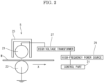
- FIG. 2 is a view schematically showing the corona treatment unit 5.
- the corona treatment unit 5 is arranged on the downstream side of the feed roller 3 in the conveyance direction X.
- the corona treatment unit 5 includes a corona discharge electrode 21 and a counter roller 23.
- the corona discharge electrode 21 is formed of, for example, a rod-shaped ceramic or an aluminum cylinder coated with ceramic, elongated in the width direction Y of the printing base material M.
- the corona discharge electrode 21 is covered with an electrode cover 25 whose lower surface is opened.
- the corona discharge electrode 21 is connected to a high-frequency power source 29 through a high-voltage transformer 27.
- the high frequency power source 29 generates a high frequency AC current.
- the high-frequency AC current is, for example, 5.5 kV to 6.5 kV.
- the higher the discharge power the higher the discharge voltage (discharge amount).
- the discharge voltage is set depending on the environmental conditions when the corona treatment is actually performed.
- the high-voltage transformer 27 amplifies the generated high-frequency AC current, converts it into a discharge power, and applies it to the corona discharge electrode 21.
- the high-frequency power source 29 is electrically connected to a control part 31, and generates a high-frequency AC current based on an instruction from the control part 31.
- the counter roller 23 is formed of, for example, a stainless steel cylinder and is grounded.
- the counter roller 23 is arranged at a predetermined interval from the corona discharge electrode 21.
- the image forming part 7 is disposed on the downstream side of the corona treatment unit 5 in the conveyance direction X.
- the image forming part 7 includes five head units 41W, 41B, 41C, 41M, and 41Y (collectively referred to as a head unit 41) corresponding to inks of five colors (white, black, cyan, magenta, and yellow), and a conveying plate 43 on which the printing base material M is conveyed along the surface.
- FIG. 3 is a plan view showing the head unit 41.
- the head unit 41 includes three print heads 45 and a plate 47 for supporting the three print heads 45.
- the three print heads 45 are arranged in a staggered pattern along the width direction Y (line head system) so as to have the same width as that of the printing base material M, and are supported by the plate 47.
- the print head 45 includes a number of nozzles (not shown). The ejection port of the nozzle is opened on the lower surface of the print head 45.
- the five head units 41W, 41B, 41C, 41M, and 41Y are arranged in order along the conveyance direction X, and the white, black, cyan, magenta, and yellow inks are supplied, respectively.
- the supplied ink is ejected downward from the ejection port of the nozzle of each print head 45.
- Each ink contains a pigment and a binder resin.
- the pigment of the white ink is titanium oxide and the binder resin is polyurethane resin.
- a viscosity ⁇ w (mPa ⁇ s) of the white ink at 25°C is smaller than a viscosity ⁇ c (mPa ⁇ s) of the inks of colors other than white at 25°C.
- an average particle diameter Dw (nm) of the pigment of the white ink is larger than an average particle diameter Dc (nm) of the pigment of the inks of colors other than white.
- the conveying plate 43 is arranged below the five head units 41.
- the upper surface of the conveying plate 43 is formed flat.
- a width of the conveying plate 43 is wider than a width of the printing base material M and all the head units 41.
- a heat source (not shown) is provided below the conveying plate 43 to heat the conveying plate 43 to a predetermined temperature.
- the conveying plate 43 is made of metal, for example.
- the drying part 9 is disposed on the downstream side of the image forming part 7 in the conveyance direction X.
- the drying part 9 includes a heat drum 51, and upstream-side and downstream-side tension rollers 53 and 55 arranged on the upstream side and the downstream side of the heat drum 51.
- the printing base material M passing through the image forming part 7 is wound around the heat drum 51 between the upstream-side and downstream-side tension rollers 53 and 55.
- the heat drum 51 is heated to heat the printing bae material M conveyed along the surface.
- the rewinding roller 11 is disposed on the downstream side of the drying part 9 in the conveyance direction X.
- the end of the printing base material M is fixed to the rewinding roller 11.
- the rewinding roller 11 is connected to a motor (not shown) and rotated. By rotating the rewinding roller 11 in a predetermined direction at a predetermined rotational speed by the motor, the printing base material M is fed out from the feed roller 3.
- the fed printing base material M passes between the corona discharge electrode 21 and the counter roller 23 in the corona treatment unit 5, and is conveyed to the image forming part 7.
- the printing base material M is conveyed toward the drying part 9 along the upper surface of the conveying plate 43 under the five head units 41. Then, after being wound on the heat drum 51 in the drying part 9, it is wound around the rewinding roller 11.
- control part 31 controls the high-frequency power source 29 of the corona treatment unit 5 to generate a high-frequency current of a predetermined intensity.
- data of the image to be printed is input.
- the control part 31 is also electrically connected to the head units 41 and controls the head units 41 based on the input image data.
- control part 31 determines whether a print job to be executed is a print job for ejecting the white ink or a print job for not ejecting the white ink, based on the input image data. Further, the control part 31 controls a discharge amount of the corona discharge electrode 21 of the corona treatment unit 5.
- the control part 31 controls the corona treatment unit 5 so as to perform the corona treatment.
- corona discharge is generated between the corona discharge electrode 21 and the counter roller 23 in the corona treatment unit 5.
- the control part 31 determines whether the print job is a print job for ejecting the white ink or not, and sets an amount of the corona discharge to W1 (W ⁇ min/m 2 ) when the print job for ejecting the white ink is performed, and sets an amount of the corona discharge to W2 (W ⁇ min/m 2 ) when the print job for not ejecting the white ink is performed.
- W1 W ⁇ min/m 2
- W2 W ⁇ min/m 2
- the motor is driven to rotate the rewinding roller 11, and the printing bae material M is fed from the feed roller 3 to the corona treatment unit 5.
- corona discharge is generated between the corona discharge electrode 21 and the counter roller 23 at the set discharge amount, and the corona discharge is applied to the upper surface of the printing base material M.
- the printing base material M is conveyed below the head units 41, and the ink of a predetermined color is ejected from the corresponding head unit 41 based on the image data to form an image on the printing base material M.
- the printing base material M on which the image is formed is conveyed to the drying part 9. In the drying part 9, the ink is completely dried. Thereafter, the printing base material M is rewound by the rewinding roller 11.
- a discharge amount in the corona treatment in the case of the print job in which the white ink is ejected is equal to or greater than a discharge amount of in the corona treatment in the case of the print job in which the white ink is not ejected.
- a discharge amount in the corona treatment in the case of the print job in which the white ink is not ejected is equal to or greater than a discharge amount of in the corona treatment in the case of the print job in which the white ink is not ejected.
- the corona discharge to the printing base material M by applying the corona discharge to the printing base material M with a higher discharge amount, even if it is the white ink, the adhesion to the printing base material M can be improved, and the peeling of the image can be prevented.
- the adhesion between the inks other than the white ink and the printing base material M is also enhanced.
- the pigment of the white ink is titanium oxide and the binder resin is polyurethane resin. Titanium oxide is known as a pigment with good contrast property. Since the polyurethane resin has good compatibility with the printing base material, the adhesion between the white ink and the printing bae material M can be enhanced.
- the white ink generally includes water and high boiling materials that have a higher boiling point than water. Water is easier to dry than the high boiling materials. Therefore, an amount of the high boiling point material contained is decreased and an amount of water is increased accordingly. As a result, a viscosity of the white ink is apparently low.
- a size (average particle diameter) of the pigment of the white ink is large.
- a viscosity of the pigment of the white ink is decreased and an average particle diameter is increased, so that the opacifying property can be improved.
- the peeling test is carried out by the following method. After the printing base material M is subjected to the corona treatment by the corona treatment unit 5, cyan and white solid images are printed on the printing base material M at 600dpi.
- the printing base material M is an OPP film, a width of the printing base material M is 210 mm, and a conveying speed of the printing bae material M is 3 m/min.
- a discharge power of the corona treatment unit 5 is 100 W (discharge voltage is 6.3 kV).
- the printed image is subjected to a peeling test based on JISK5600 (a cross cut is not formed).
- a tape (Product name: CT18, manufactured by NICHIBAN) is firmly rubbed onto the image with a fingertip, and within 5 minutes, the tape is peeled off, or the edge of the tape is grasped at an angle of close to 60 degrees and firmly pulled away within 0.5 to 1.0 seconds.
- FIG. 4A is a photograph showing the cyan solid image after the tape is peeled
- FIG. 4B is a photograph showing the white solid image after the tape is peeled
- FIG. 4C is a comparative photograph of the white solid image without the corona treatment after the tape is peeled off.
- the left side shows the printing base material from which the tape is peeled
- the right side shows the peeled tape.
- FIG. 4A when the corona treatment is applied, no image peeling is observed in the cyan solid image. As shown in FIG. 4B , no image peeling is observed even in the white solid image. On the other hand, as shown in FIG. 4C , the white image peeling is observed when the corona treatment is not performed.
- the adhesion is evaluated by an image density of the peeled tape in the peeling test described above.
- an unused tape and the peeled tape are pasted on a copy paper (Product name C2, manufactured by Fujifilm Business Innovation Co., Ltd.), and the image density is measured by an image densitometer (Product name FD-5, manufactured by Konica Minolta).
- an image densitometer Product name FD-5, manufactured by Konica Minolta
- the opacifying property is evaluated by the following methods.
- the image formed on the printing base material is placed on a black area of a contrast ratio test paper (manufactured by TP Giken Co., Ltd.), and a density of the black color is measured using a spectral colorimeter (Product name CM-25cG, manufactured by Konica Minolta).
- a spectral colorimeter Product name CM-25cG, manufactured by Konica Minolta.
- the corona discharge amount is larger than or equal to the discharge amount of the inks other than the white ink.
- an amount of corona discharge for the white ink is about 1.125 to 1.25 times (or 90 W ⁇ min/m 2 or more) of an amount of corona discharge for the inks other than white ink.
- Example 6 when a viscosity of the white ink is increased, sufficient adhesion is not obtained. This is because a viscosity of the ink is high and the ink could not be sufficiently dried. Further, as shown in Example 7, when a particle size of the white ink is decreased, sufficient opacifying property is not obtained.
- a viscosity of the white ink is preferably less than 6.0 (mPa-s) and an average particle diameter is preferably 200 (nm) or more.
- Comparative Example 1 when a viscosity of the white ink is low and an average particle diameter is large, the adhesion becomes insufficient if the corona discharge amount is low (see also FIG. 4C ).
- a soft-packaged printed matter is formed by laminating a plurality of films on a printing base material on which an image is formed. For this reason, a step of laminating the films is included. In which case, it is preferable from the viewpoint of productivity to perform a front printing after the laminating step.
- the white ink is required in the lowermost layer, and therefore, it is preferable that the head unit 41W for ejecting the white ink is disposed on the upstream side of the head units for ejecting the inks of other colors in the conveyance direction X.
- the drying part 9 is arranged on the downstream side of the five head units 41.
- the drying part for the white ink may be separately provided on the downstream side of the head unit 41W for ejecting the white ink.
- the present disclosure is not limited to five colors, but may be more or less than five colors.
- the head unit 41 is not limited to the line head system. However, the line head system is preferable because the printing speed can be increased. Although a long plastic film (PET film) is used as the printing base material M, a cut film may be used.
- PET film plastic film
Landscapes
- Chemical & Material Sciences (AREA)
- Life Sciences & Earth Sciences (AREA)
- Engineering & Computer Science (AREA)
- Materials Engineering (AREA)
- Wood Science & Technology (AREA)
- Organic Chemistry (AREA)
- Chemical Kinetics & Catalysis (AREA)
- General Chemical & Material Sciences (AREA)
- Ink Jet (AREA)
- Ink Jet Recording Methods And Recording Media Thereof (AREA)
- Particle Formation And Scattering Control In Inkjet Printers (AREA)
Abstract
An inkjet image forming apparatus (1) includes a plurality of head unit (41), a corona treatment unit (5), and a control part (31). The head units (41) are provided for inks of a plurality of colors including white, and eject the ink to a printing base material which is conveyed along a predetermined conveyance direction. The corona treatment unit (5) is arranged on an upstream side of the head units (41) in the conveyance direction and applies corona discharge to the printing base material. The control part (31) controls a discharge amount of the corona discharge applied by the corona treatment unit (5). The control part (31) controls the discharge amount so that W1≧W2 when the discharge amount in a case of a print job for ejecting the white ink is set to W1 (W·min/m<sup>2</sup>) and the discharge amount in a case of a print job for not ejecting the white ink is set to W2 (W·min/m<sup>2</sup>).
Description
- The present disclosure relates to an inkjet image forming apparatus which forms an image on a printing base material by an inkjet method.
- In the inkjet type image forming apparatus, as described in
WO2017/187905 andJP2022-191181 - In the printing apparatus described in
WO2017/18790 JP2022-1911 - In general, it is known that the white ink is easily peeled off from the printing base material. This is because it is necessary to increase a particle size of a pigment in order to increase a contrast ratio of the white color, and but in this case, the pigment cannot be completely coated with a binder resin, resulting in poor adhesion to the printing base material. This tendency is particularly strong in the case of a printing base material having a smooth surface such as a plastic film.
- An inkjet image forming apparatus according to the present disclosure includes a plurality of head units, a corona treatment unit, and a control part. The head units are provided for inks of a plurality of colors including white, and ejects the ink to a printing base material which is conveyed along a predetermined conveyance direction. The corona treatment unit is arranged on an upstream side of the head units in the conveyance direction and applies corona discharge to the printing base material. The control part controls a discharge amount of the corona discharge applied by the corona treatment unit. The control part controls the discharge amount so that W1≧W2 when the discharge amount in a case of a print job for ejecting the white ink is set to W1 (W·min/m2) and the discharge amount in a case of a print job for not ejecting the white ink is set to W2 (W·min/m2).
-
-
FIG. 1 is a front view schematically showing one inkjet image forming apparatus according to one embodiment of the present disclosure. -
FIG. 2 is a view schematically showing a corona treatment unit, in the inkjet image forming apparatus according to one embodiment of the present disclosure. -
FIG. 3 is a plan view showing a head unit, in the inkjet image forming apparatus according to the embodiment of the present disclosure. -
FIG. 4A is a photograph showing a result (magenta image) of a peeling test, in the inkjet image forming apparatus according to the embodiment of the present disclosure. -
FIG. 4B is a photograph showing a result (white image, the corona-treatment is performed) of the peeling test, in the inkjet image forming apparatus according to the embodiment of the present disclosure. -
FIG. 4C is a photograph showing a result (white image, the corona-treatment is not performed) of the peeling test, in the inkjet image forming apparatus according to the embodiment of the present disclosure. -
FIG. 5 is a table showing a result of evaluation test of adhesion and opacifying property, in the inkjet image forming apparatus according to the embodiment of the present disclosure. - Hereinafter, with reference to the drawings, an inkjet image forming apparatus according to one embodiment of the present disclosure will be described.
- With reference to
FIG. 1 , an entire configuration of the inkjetimage forming apparatus 1 will be described.FIG. 1 is a front view schematically showing an internal configuration of the inkjetimage forming apparatus 1. - The inkjet
image forming apparatus 1 includes afeed roller 3 around which a long printing base material M is wound, acorona treatment unit 5 which performs a corona treatment in which the printing base material M fed from thefeed roller 3 is corona-discharged, animage forming part 7 which forms an image on the printing base material M subjected to the corona treatment by an inkjet method, a dryingpart 9 which dries the image formed by theimage forming part 7, and a rewindingroller 11 which rewinds the printing base material M dried by the dryingpart 9. - First, the
feed roller 3 will be described. The printing base material M is wound and mounted on thefeed roller 3. When thefeed roller 3 is rotated, the printing base material M is fed out in a predetermined conveyance direction X. - Next, the
corona treatment unit 5 will be described with reference toFIG. 2. FIG. 2 is a view schematically showing thecorona treatment unit 5. Thecorona treatment unit 5 is arranged on the downstream side of thefeed roller 3 in the conveyance direction X. Thecorona treatment unit 5 includes acorona discharge electrode 21 and acounter roller 23. - The
corona discharge electrode 21 is formed of, for example, a rod-shaped ceramic or an aluminum cylinder coated with ceramic, elongated in the width direction Y of the printing base material M. Thecorona discharge electrode 21 is covered with anelectrode cover 25 whose lower surface is opened. Thecorona discharge electrode 21 is connected to a high-frequency power source 29 through a high-voltage transformer 27. The highfrequency power source 29 generates a high frequency AC current. The high-frequency AC current is, for example, 5.5 kV to 6.5 kV. The higher the discharge power, the higher the discharge voltage (discharge amount). However, since the discharge voltage varies depending on the atmospheric pressure, temperature and humidity, and the others, the discharge voltage is set depending on the environmental conditions when the corona treatment is actually performed. The high-voltage transformer 27 amplifies the generated high-frequency AC current, converts it into a discharge power, and applies it to thecorona discharge electrode 21. The high-frequency power source 29 is electrically connected to acontrol part 31, and generates a high-frequency AC current based on an instruction from thecontrol part 31. - The
counter roller 23 is formed of, for example, a stainless steel cylinder and is grounded. Thecounter roller 23 is arranged at a predetermined interval from thecorona discharge electrode 21. - Next, the
image forming part 7 will be described with reference toFIG. 1 . Theimage forming part 7 is disposed on the downstream side of thecorona treatment unit 5 in the conveyance direction X. Theimage forming part 7 includes fivehead units conveying plate 43 on which the printing base material M is conveyed along the surface. - The
head unit 41 will be described with reference toFIG. 3. FIG. 3 is a plan view showing thehead unit 41. Thehead unit 41 includes threeprint heads 45 and aplate 47 for supporting the threeprint heads 45. - As shown in
FIG. 3 , the threeprint heads 45 are arranged in a staggered pattern along the width direction Y (line head system) so as to have the same width as that of the printing base material M, and are supported by theplate 47. Theprint head 45 includes a number of nozzles (not shown). The ejection port of the nozzle is opened on the lower surface of theprint head 45. - The five
head units print head 45. Each ink contains a pigment and a binder resin. - The pigment of the white ink is titanium oxide and the binder resin is polyurethane resin. A viscosity ρw (mPa·s) of the white ink at 25°C is smaller than a viscosity ρc (mPa·s) of the inks of colors other than white at 25°C. Further, an average particle diameter Dw (nm) of the pigment of the white ink is larger than an average particle diameter Dc (nm) of the pigment of the inks of colors other than white.
- As shown in
FIG. 1 , the conveyingplate 43 is arranged below the fivehead units 41. The upper surface of the conveyingplate 43 is formed flat. As shown inFIG. 3 , a width of the conveyingplate 43 is wider than a width of the printing base material M and all thehead units 41. A heat source (not shown) is provided below the conveyingplate 43 to heat the conveyingplate 43 to a predetermined temperature. The conveyingplate 43 is made of metal, for example. - Next, the drying
part 9 will be described. The dryingpart 9 is disposed on the downstream side of theimage forming part 7 in the conveyance direction X. The dryingpart 9 includes aheat drum 51, and upstream-side and downstream-side tension rollers heat drum 51. The printing base material M passing through theimage forming part 7 is wound around theheat drum 51 between the upstream-side and downstream-side tension rollers heat drum 51 is heated to heat the printing bae material M conveyed along the surface. - Next, the rewinding
roller 11 will be described. The rewindingroller 11 is disposed on the downstream side of the dryingpart 9 in the conveyance direction X. The end of the printing base material M is fixed to the rewindingroller 11. The rewindingroller 11 is connected to a motor (not shown) and rotated. By rotating the rewindingroller 11 in a predetermined direction at a predetermined rotational speed by the motor, the printing base material M is fed out from thefeed roller 3. - The fed printing base material M passes between the
corona discharge electrode 21 and thecounter roller 23 in thecorona treatment unit 5, and is conveyed to theimage forming part 7. In theimage forming part 7, the printing base material M is conveyed toward the dryingpart 9 along the upper surface of the conveyingplate 43 under the fivehead units 41. Then, after being wound on theheat drum 51 in the dryingpart 9, it is wound around the rewindingroller 11. - Next, the
control part 31 will be described. As shown inFIG. 2 , thecontrol part 31 controls the high-frequency power source 29 of thecorona treatment unit 5 to generate a high-frequency current of a predetermined intensity. To thecontrol part 31, data of the image to be printed is input. Thecontrol part 31 is also electrically connected to thehead units 41 and controls thehead units 41 based on the input image data. - Further, the
control part 31 determines whether a print job to be executed is a print job for ejecting the white ink or a print job for not ejecting the white ink, based on the input image data. Further, thecontrol part 31 controls a discharge amount of thecorona discharge electrode 21 of thecorona treatment unit 5. - An image forming operation on a non-absorbent base material (plastic film) in the inkjet
image forming apparatus 1 having the above configuration will be described. In the image forming operation, thecontrol part 31 controls thecorona treatment unit 5 so as to perform the corona treatment. Thus, corona discharge is generated between thecorona discharge electrode 21 and thecounter roller 23 in thecorona treatment unit 5. Here, thecontrol part 31 determines whether the print job is a print job for ejecting the white ink or not, and sets an amount of the corona discharge to W1 (W·min/m2) when the print job for ejecting the white ink is performed, and sets an amount of the corona discharge to W2 (W·min/m2) when the print job for not ejecting the white ink is performed. Here, W1≧W2. Note that W2 may be zero. When the printing base material M is not non-absorbent, the corona treatment by thecorona treatment unit 5 is not performed. - Thereafter, the motor is driven to rotate the rewinding
roller 11, and the printing bae material M is fed from thefeed roller 3 to thecorona treatment unit 5. In thecorona treatment unit 5, corona discharge is generated between thecorona discharge electrode 21 and thecounter roller 23 at the set discharge amount, and the corona discharge is applied to the upper surface of the printing base material M. - Thereafter, the printing base material M is conveyed below the
head units 41, and the ink of a predetermined color is ejected from the correspondinghead unit 41 based on the image data to form an image on the printing base material M. The printing base material M on which the image is formed is conveyed to the dryingpart 9. In the dryingpart 9, the ink is completely dried. Thereafter, the printing base material M is rewound by the rewindingroller 11. - As described above, according to the present disclosure, a discharge amount in the corona treatment in the case of the print job in which the white ink is ejected is equal to or greater than a discharge amount of in the corona treatment in the case of the print job in which the white ink is not ejected. As described above, in order to increase a contrast ratio of the white ink, it is necessary to increase a particle size of the pigment, and in this case, the pigment cannot be completely coated with the binder resin, resulting in poor adhesion to the printing base material M. Therefore, the adhesion between the printing base material M and the ink can be improved by applying the corona discharge to the printing base material M. That is, when the printing base material M is subjected to the corona treatment, fine irregularities are formed on the surface of the printing base material M, and the ink easily enters these irregularities (anchor effect). Further, hydrophilic polar groups such as carbonyl groups, carboxyl groups and nitrides are formed on the surface of the printing base material M. Such a polar group enhances a wettability of the surface of the printing base material M. Therefore, the physical and chemical actions of the corona discharge treatment improve a compatibility (adhesion) between the printing base material M and the ink.
- Therefore, in the case of the print job in which the white ink is ejected, by applying the corona discharge to the printing base material M with a higher discharge amount, even if it is the white ink, the adhesion to the printing base material M can be improved, and the peeling of the image can be prevented. The adhesion between the inks other than the white ink and the printing base material M is also enhanced.
- The pigment of the white ink is titanium oxide and the binder resin is polyurethane resin. Titanium oxide is known as a pigment with good contrast property. Since the polyurethane resin has good compatibility with the printing base material, the adhesion between the white ink and the printing bae material M can be enhanced.
- Further, a large amount of the white ink is ejected in order to improve the contrast property of the white ink. However, when an amount of the ejected ink increases, a dryness of the ejected ink decreases. The white ink generally includes water and high boiling materials that have a higher boiling point than water. Water is easier to dry than the high boiling materials. Therefore, an amount of the high boiling point material contained is decreased and an amount of water is increased accordingly. As a result, a viscosity of the white ink is apparently low.
- In order to improve an opacifying property of the white ink, it is preferable that a size (average particle diameter) of the pigment of the white ink is large. In this embodiment, a viscosity of the pigment of the white ink is decreased and an average particle diameter is increased, so that the opacifying property can be improved.
- Next, a test for evaluating adhesion of the ink in the inkjet
image forming apparatus 1 of this embodiment will be described with reference toFIG. 4A to FIG. 4C . The adhesion is evaluated by a peeling test. - The peeling test is carried out by the following method. After the printing base material M is subjected to the corona treatment by the
corona treatment unit 5, cyan and white solid images are printed on the printing base material M at 600dpi. The printing base material M is an OPP film, a width of the printing base material M is 210 mm, and a conveying speed of the printing bae material M is 3 m/min. A discharge power of thecorona treatment unit 5 is 100 W (discharge voltage is 6.3 kV). - The printed image is subjected to a peeling test based on JISK5600 (a cross cut is not formed). A tape (Product name: CT18, manufactured by NICHIBAN) is firmly rubbed onto the image with a fingertip, and within 5 minutes, the tape is peeled off, or the edge of the tape is grasped at an angle of close to 60 degrees and firmly pulled away within 0.5 to 1.0 seconds.
-
FIG. 4A is a photograph showing the cyan solid image after the tape is peeled, andFIG. 4B is a photograph showing the white solid image after the tape is peeled.FIG. 4C is a comparative photograph of the white solid image without the corona treatment after the tape is peeled off. In each figure, the left side shows the printing base material from which the tape is peeled, and the right side shows the peeled tape. - As shown in
FIG. 4A , when the corona treatment is applied, no image peeling is observed in the cyan solid image. As shown inFIG. 4B , no image peeling is observed even in the white solid image. On the other hand, as shown inFIG. 4C , the white image peeling is observed when the corona treatment is not performed. - Next, a test in which the adhesion and opacifying property of the ink are evaluated in the inkjet
image forming apparatus 1 of this embodiment will be described with reference to the table inFIG. 5 . - The adhesion is evaluated by an image density of the peeled tape in the peeling test described above. In detail, an unused tape and the peeled tape are pasted on a copy paper (Product name C2, manufactured by Fujifilm Business Innovation Co., Ltd.), and the image density is measured by an image densitometer (Product name FD-5, manufactured by Konica Minolta). When a difference between the image density of the unused tape and the image density of the peeled tape is less than 0.05, it is defined as "o", when the difference is less than 0.15, it is defined as "Δ", and when the difference is 0.15 or more, it is defined as "x".
- The opacifying property is evaluated by the following methods. The image formed on the printing base material is placed on a black area of a contrast ratio test paper (manufactured by TP Giken Co., Ltd.), and a density of the black color is measured using a spectral colorimeter (Product name CM-25cG, manufactured by Konica Minolta). When the image density is less than 0.2, it is defined as "o", when the image density is less than 0.3, it is defined as "Δ", and when the image density is 0.3 or more, it is defined as "x".
- As shown in Examples 1 to 5, when a viscosity of the white ink is decreased and an average particle diameter is increased, by performing the corona treatment, good results are obtained in both the adhesion and the opacifying property. In this case, the corona discharge amount is larger than or equal to the discharge amount of the inks other than the white ink. In this example, it is preferable that an amount of corona discharge for the white ink is about 1.125 to 1.25 times (or 90 W·min/m2 or more) of an amount of corona discharge for the inks other than white ink.
- On the other hand, as shown in Example 6, when a viscosity of the white ink is increased, sufficient adhesion is not obtained. This is because a viscosity of the ink is high and the ink could not be sufficiently dried. Further, as shown in Example 7, when a particle size of the white ink is decreased, sufficient opacifying property is not obtained. In this example, a viscosity of the white ink is preferably less than 6.0 (mPa-s) and an average particle diameter is preferably 200 (nm) or more.
- Further, as shown in Comparative Example 1, when a viscosity of the white ink is low and an average particle diameter is large, the adhesion becomes insufficient if the corona discharge amount is low (see also
FIG. 4C ). - Generally, a soft-packaged printed matter is formed by laminating a plurality of films on a printing base material on which an image is formed. For this reason, a step of laminating the films is included. In which case, it is preferable from the viewpoint of productivity to perform a front printing after the laminating step. In the case of front printing, the white ink is required in the lowermost layer, and therefore, it is preferable that the
head unit 41W for ejecting the white ink is disposed on the upstream side of the head units for ejecting the inks of other colors in the conveyance direction X. - In the above embodiment, the drying
part 9 is arranged on the downstream side of the fivehead units 41. However, the drying part for the white ink may be separately provided on the downstream side of thehead unit 41W for ejecting the white ink. - Although the embodiments described above use the
head units 41 of five colors, the present disclosure is not limited to five colors, but may be more or less than five colors. Thehead unit 41 is not limited to the line head system. However, the line head system is preferable because the printing speed can be increased. Although a long plastic film (PET film) is used as the printing base material M, a cut film may be used. - Although the present disclosure has been described with respect to specific embodiments, the present disclosure is not limited to the above embodiments. The above embodiments can be modified by those skilled in the art without departing from the scope and spirit of the present disclosure.
Claims (7)
- An inkjet image forming apparatus (1) comprising:a plurality of head units (41) which are provided for inks of a plurality of colors including white and ejects the ink to a printing base material which is conveyed along a predetermined conveyance direction;a corona treatment unit (5) which is arranged on an upstream side of the head units (41) in the conveyance direction and applies corona discharge to the printing base material; anda control part (31) which controls a discharge amount of the corona discharge applied by the corona treatment unit (5), whereinthe control part (31) controls the discharge amount so that W1≧W2 when the discharge amount in a case of a print job for ejecting the white ink is set to W1 (W· min/m2) and the discharge amount in a case of a print job for not ejecting the white ink is set to W2 (W·min/m2).
- The inkjet image forming apparatus (1) according to claim 1, wherein
the head unit (41W) ejecting the white ink is arranged on the upstream side of the head units (41B), (41C), (41M), (41B) ejecting the ink of other color in the conveyance direction - The inkjet image forming apparatus (1) according to claim 1, wherein
a pigment of the white ink is titanium oxide. - The inkjet image forming apparatus (1) according to claim 1, wherein
a binder resin of the white ink is a polyurethane resin. - The inkjet image forming apparatus (1) according to claim 1, wherein
the printing base material is a plastic film. - The inkjet image forming apparatus (1) according to claim 1, wherein
when a viscosity of the white ink at 25°C is set to ρw (mPa·s) and a viscosity of the inks of colors other than white at 25°C is set to ρc (mPa-s), then ρw<ρc. - The inkjet image forming apparatus (1) according to claim 1, wherein:
when an average particle diameter of the pigment of the white ink is set to Dw (nm) and an average particle diameter of the pigment of the inks of colors other than white is set to Dc (nm), then Dw>Dc.
Applications Claiming Priority (1)
| Application Number | Priority Date | Filing Date | Title |
|---|---|---|---|
| JP2023205304A JP2025090209A (en) | 2023-12-05 | 2023-12-05 | Inkjet image forming device |
Publications (1)
| Publication Number | Publication Date |
|---|---|
| EP4566825A1 true EP4566825A1 (en) | 2025-06-11 |
Family
ID=93743784
Family Applications (1)
| Application Number | Title | Priority Date | Filing Date |
|---|---|---|---|
| EP24216746.8A Pending EP4566825A1 (en) | 2023-12-05 | 2024-12-02 | Inkjet image forming apparatus |
Country Status (3)
| Country | Link |
|---|---|
| US (1) | US20250178361A1 (en) |
| EP (1) | EP4566825A1 (en) |
| JP (1) | JP2025090209A (en) |
Citations (7)
| Publication number | Priority date | Publication date | Assignee | Title |
|---|---|---|---|---|
| JP5313163B2 (en) * | 2006-12-21 | 2013-10-09 | アグファ・グラフィクス・エヌヴィ | Inkjet printing method and inkjet ink set |
| WO2017018790A1 (en) | 2015-07-30 | 2017-02-02 | 엘지이노텍 주식회사 | Substrate unit and substrate assembly, and camera module using same |
| WO2017187905A1 (en) | 2016-04-28 | 2017-11-02 | コニカミノルタ株式会社 | Image forming method and image forming apparatus |
| JP2022001911A (en) | 2020-06-22 | 2022-01-06 | 株式会社ジャパンディスプレイ | Display device |
| EP3730559B1 (en) * | 2017-12-20 | 2022-11-02 | Konica Minolta, Inc. | Active ray-curable inkjet ink set and inkjet recording method |
| JP2022191181A (en) | 2021-06-15 | 2022-12-27 | キヤノン株式会社 | Inkjet recording device and inkjet recording method |
| US20230037226A1 (en) * | 2021-07-30 | 2023-02-02 | Seiko Epson Corporation | Recording device and recording method |
-
2023
- 2023-12-05 JP JP2023205304A patent/JP2025090209A/en active Pending
-
2024
- 2024-12-02 EP EP24216746.8A patent/EP4566825A1/en active Pending
- 2024-12-02 US US18/965,461 patent/US20250178361A1/en active Pending
Patent Citations (7)
| Publication number | Priority date | Publication date | Assignee | Title |
|---|---|---|---|---|
| JP5313163B2 (en) * | 2006-12-21 | 2013-10-09 | アグファ・グラフィクス・エヌヴィ | Inkjet printing method and inkjet ink set |
| WO2017018790A1 (en) | 2015-07-30 | 2017-02-02 | 엘지이노텍 주식회사 | Substrate unit and substrate assembly, and camera module using same |
| WO2017187905A1 (en) | 2016-04-28 | 2017-11-02 | コニカミノルタ株式会社 | Image forming method and image forming apparatus |
| EP3730559B1 (en) * | 2017-12-20 | 2022-11-02 | Konica Minolta, Inc. | Active ray-curable inkjet ink set and inkjet recording method |
| JP2022001911A (en) | 2020-06-22 | 2022-01-06 | 株式会社ジャパンディスプレイ | Display device |
| JP2022191181A (en) | 2021-06-15 | 2022-12-27 | キヤノン株式会社 | Inkjet recording device and inkjet recording method |
| US20230037226A1 (en) * | 2021-07-30 | 2023-02-02 | Seiko Epson Corporation | Recording device and recording method |
Also Published As
| Publication number | Publication date |
|---|---|
| JP2025090209A (en) | 2025-06-17 |
| US20250178361A1 (en) | 2025-06-05 |
Similar Documents
| Publication | Publication Date | Title |
|---|---|---|
| US9108437B2 (en) | Printing apparatus, treatment object modifying apparatus, printing system, and printed material manufacturing method | |
| JP6317664B2 (en) | Inkjet printing apparatus, inkjet printing method, and inkjet printing system | |
| US9643429B2 (en) | Processing object modifying apparatus, printing apparatus, printing system, and method for manufacturing printout | |
| EP2974871B1 (en) | Printing apparatus, printing system, printed material manufacturing method, and computer program product | |
| MX2014000506A (en) | System and method for image surface preparation in an aqueous inkjet printer. | |
| US9242482B2 (en) | pH detecting device, printing system, and method for manufacturing printed material | |
| JP2015180529A (en) | Plasma treatment device, printing device, printing system, program, and printed matter manufacturing method | |
| US8474970B2 (en) | Recording medium conveyance method and apparatus, and image forming apparatus | |
| JP2018051954A (en) | Inkjet printing apparatus and method for setting dry strength thereof | |
| US20250178361A1 (en) | Inkjet image forming apparatus | |
| JP7380173B2 (en) | printing device | |
| US20250100296A1 (en) | Inkjet image forming apparatus | |
| US20250222701A1 (en) | Inkjet image forming apparatus | |
| US20250222703A1 (en) | Inkjet image forming apparatus | |
| JP5363296B2 (en) | Image forming apparatus and image forming method | |
| JP2010158813A (en) | Inkjet recording method and apparatus | |
| US20240383261A1 (en) | Image forming apparatus | |
| JP7307395B2 (en) | Drying device, device for discharging liquid | |
| JP2013215994A (en) | Printer and printing method | |
| JP2025108120A (en) | Inkjet image forming device | |
| US20250010613A1 (en) | Image forming apparatus | |
| US20250100297A1 (en) | Inkjet image forming apparatus | |
| US20220024205A1 (en) | Media assembly including surface treatment | |
| US20260138379A1 (en) | Inkjet image forming apparatus | |
| US20250108627A1 (en) | Inkjet image forming apparatus |
Legal Events
| Date | Code | Title | Description |
|---|---|---|---|
| PUAI | Public reference made under article 153(3) epc to a published international application that has entered the european phase |
Free format text: ORIGINAL CODE: 0009012 |
|
| STAA | Information on the status of an ep patent application or granted ep patent |
Free format text: STATUS: THE APPLICATION HAS BEEN PUBLISHED |
|
| AK | Designated contracting states |
Kind code of ref document: A1 Designated state(s): AL AT BE BG CH CY CZ DE DK EE ES FI FR GB GR HR HU IE IS IT LI LT LU LV MC ME MK MT NL NO PL PT RO RS SE SI SK SM TR |
|
| STAA | Information on the status of an ep patent application or granted ep patent |
Free format text: STATUS: REQUEST FOR EXAMINATION WAS MADE |
|
| 17P | Request for examination filed |
Effective date: 20250804 |