EP4566754A1 - Projection polishing system, projection polishing method, and method for manufacturing steel product - Google Patents
Projection polishing system, projection polishing method, and method for manufacturing steel product Download PDFInfo
- Publication number
- EP4566754A1 EP4566754A1 EP23877087.9A EP23877087A EP4566754A1 EP 4566754 A1 EP4566754 A1 EP 4566754A1 EP 23877087 A EP23877087 A EP 23877087A EP 4566754 A1 EP4566754 A1 EP 4566754A1
- Authority
- EP
- European Patent Office
- Prior art keywords
- grinding
- convex portion
- trajectory
- grinding tool
- control device
- Prior art date
- Legal status (The legal status is an assumption and is not a legal conclusion. Google has not performed a legal analysis and makes no representation as to the accuracy of the status listed.)
- Pending
Links
Images



Classifications
-
- B—PERFORMING OPERATIONS; TRANSPORTING
- B24—GRINDING; POLISHING
- B24B—MACHINES, DEVICES, OR PROCESSES FOR GRINDING OR POLISHING; DRESSING OR CONDITIONING OF ABRADING SURFACES; FEEDING OF GRINDING, POLISHING, OR LAPPING AGENTS
- B24B49/00—Measuring or gauging equipment for controlling the feed movement of the grinding tool or work; Arrangements of indicating or measuring equipment, e.g. for indicating the start of the grinding operation
- B24B49/12—Measuring or gauging equipment for controlling the feed movement of the grinding tool or work; Arrangements of indicating or measuring equipment, e.g. for indicating the start of the grinding operation involving optical means
-
- B—PERFORMING OPERATIONS; TRANSPORTING
- B24—GRINDING; POLISHING
- B24B—MACHINES, DEVICES, OR PROCESSES FOR GRINDING OR POLISHING; DRESSING OR CONDITIONING OF ABRADING SURFACES; FEEDING OF GRINDING, POLISHING, OR LAPPING AGENTS
- B24B19/00—Single-purpose machines or devices for particular grinding operations not covered by any other main group
- B24B19/26—Single-purpose machines or devices for particular grinding operations not covered by any other main group for grinding workpieces with arcuate surfaces, e.g. parts of car bodies, bumpers or magnetic recording heads
-
- B—PERFORMING OPERATIONS; TRANSPORTING
- B24—GRINDING; POLISHING
- B24B—MACHINES, DEVICES, OR PROCESSES FOR GRINDING OR POLISHING; DRESSING OR CONDITIONING OF ABRADING SURFACES; FEEDING OF GRINDING, POLISHING, OR LAPPING AGENTS
- B24B27/00—Other grinding machines or devices
- B24B27/0038—Other grinding machines or devices with the grinding tool mounted at the end of a set of bars
-
- B—PERFORMING OPERATIONS; TRANSPORTING
- B24—GRINDING; POLISHING
- B24B—MACHINES, DEVICES, OR PROCESSES FOR GRINDING OR POLISHING; DRESSING OR CONDITIONING OF ABRADING SURFACES; FEEDING OF GRINDING, POLISHING, OR LAPPING AGENTS
- B24B49/00—Measuring or gauging equipment for controlling the feed movement of the grinding tool or work; Arrangements of indicating or measuring equipment, e.g. for indicating the start of the grinding operation
- B24B49/02—Measuring or gauging equipment for controlling the feed movement of the grinding tool or work; Arrangements of indicating or measuring equipment, e.g. for indicating the start of the grinding operation according to the instantaneous size and required size of the workpiece acted upon, the measuring or gauging being continuous or intermittent
-
- B—PERFORMING OPERATIONS; TRANSPORTING
- B24—GRINDING; POLISHING
- B24B—MACHINES, DEVICES, OR PROCESSES FOR GRINDING OR POLISHING; DRESSING OR CONDITIONING OF ABRADING SURFACES; FEEDING OF GRINDING, POLISHING, OR LAPPING AGENTS
- B24B49/00—Measuring or gauging equipment for controlling the feed movement of the grinding tool or work; Arrangements of indicating or measuring equipment, e.g. for indicating the start of the grinding operation
- B24B49/16—Measuring or gauging equipment for controlling the feed movement of the grinding tool or work; Arrangements of indicating or measuring equipment, e.g. for indicating the start of the grinding operation taking regard of the load
-
- B—PERFORMING OPERATIONS; TRANSPORTING
- B24—GRINDING; POLISHING
- B24B—MACHINES, DEVICES, OR PROCESSES FOR GRINDING OR POLISHING; DRESSING OR CONDITIONING OF ABRADING SURFACES; FEEDING OF GRINDING, POLISHING, OR LAPPING AGENTS
- B24B51/00—Arrangements for automatic control of a series of individual steps in grinding a workpiece
-
- B—PERFORMING OPERATIONS; TRANSPORTING
- B25—HAND TOOLS; PORTABLE POWER-DRIVEN TOOLS; MANIPULATORS
- B25J—MANIPULATORS; CHAMBERS PROVIDED WITH MANIPULATION DEVICES
- B25J11/00—Manipulators not otherwise provided for
- B25J11/005—Manipulators for mechanical processing tasks
- B25J11/0065—Polishing or grinding
-
- B—PERFORMING OPERATIONS; TRANSPORTING
- B25—HAND TOOLS; PORTABLE POWER-DRIVEN TOOLS; MANIPULATORS
- B25J—MANIPULATORS; CHAMBERS PROVIDED WITH MANIPULATION DEVICES
- B25J13/00—Controls for manipulators
- B25J13/08—Controls for manipulators by means of sensing devices, e.g. viewing or touching devices
-
- B—PERFORMING OPERATIONS; TRANSPORTING
- B25—HAND TOOLS; PORTABLE POWER-DRIVEN TOOLS; MANIPULATORS
- B25J—MANIPULATORS; CHAMBERS PROVIDED WITH MANIPULATION DEVICES
- B25J13/00—Controls for manipulators
- B25J13/08—Controls for manipulators by means of sensing devices, e.g. viewing or touching devices
- B25J13/085—Force or torque sensors
-
- B—PERFORMING OPERATIONS; TRANSPORTING
- B25—HAND TOOLS; PORTABLE POWER-DRIVEN TOOLS; MANIPULATORS
- B25J—MANIPULATORS; CHAMBERS PROVIDED WITH MANIPULATION DEVICES
- B25J9/00—Program-controlled manipulators
- B25J9/16—Program controls
- B25J9/1628—Program controls characterised by the control loop
- B25J9/1638—Program controls characterised by the control loop compensation for arm bending/inertia, pay load weight/inertia
-
- B—PERFORMING OPERATIONS; TRANSPORTING
- B25—HAND TOOLS; PORTABLE POWER-DRIVEN TOOLS; MANIPULATORS
- B25J—MANIPULATORS; CHAMBERS PROVIDED WITH MANIPULATION DEVICES
- B25J9/00—Program-controlled manipulators
- B25J9/16—Program controls
- B25J9/1628—Program controls characterised by the control loop
- B25J9/1653—Program controls characterised by the control loop parameters identification, estimation, stiffness, accuracy, error analysis
-
- B—PERFORMING OPERATIONS; TRANSPORTING
- B25—HAND TOOLS; PORTABLE POWER-DRIVEN TOOLS; MANIPULATORS
- B25J—MANIPULATORS; CHAMBERS PROVIDED WITH MANIPULATION DEVICES
- B25J9/00—Program-controlled manipulators
- B25J9/16—Program controls
- B25J9/1656—Program controls characterised by programming, planning systems for manipulators
- B25J9/1664—Program controls characterised by programming, planning systems for manipulators characterised by motion, path, trajectory planning
-
- B—PERFORMING OPERATIONS; TRANSPORTING
- B25—HAND TOOLS; PORTABLE POWER-DRIVEN TOOLS; MANIPULATORS
- B25J—MANIPULATORS; CHAMBERS PROVIDED WITH MANIPULATION DEVICES
- B25J9/00—Program-controlled manipulators
- B25J9/16—Program controls
- B25J9/1694—Program controls characterised by use of sensors other than normal servo-feedback from position, speed or acceleration sensors, perception control, multi-sensor controlled systems, sensor fusion
- B25J9/1697—Vision controlled systems
-
- G—PHYSICS
- G05—CONTROLLING; REGULATING
- G05B—CONTROL OR REGULATING SYSTEMS IN GENERAL; FUNCTIONAL ELEMENTS OF SUCH SYSTEMS; MONITORING OR TESTING ARRANGEMENTS FOR SUCH SYSTEMS OR ELEMENTS
- G05B2219/00—Program-control systems
- G05B2219/30—Nc systems
- G05B2219/40—Robotics, robotics mapping to robotics vision
- G05B2219/40564—Recognize shape, contour of object, extract position and orientation
-
- G—PHYSICS
- G05—CONTROLLING; REGULATING
- G05B—CONTROL OR REGULATING SYSTEMS IN GENERAL; FUNCTIONAL ELEMENTS OF SUCH SYSTEMS; MONITORING OR TESTING ARRANGEMENTS FOR SUCH SYSTEMS OR ELEMENTS
- G05B2219/00—Program-control systems
- G05B2219/30—Nc systems
- G05B2219/40—Robotics, robotics mapping to robotics vision
- G05B2219/40607—Fixed camera to observe workspace, object, workpiece, global
-
- G—PHYSICS
- G05—CONTROLLING; REGULATING
- G05B—CONTROL OR REGULATING SYSTEMS IN GENERAL; FUNCTIONAL ELEMENTS OF SUCH SYSTEMS; MONITORING OR TESTING ARRANGEMENTS FOR SUCH SYSTEMS OR ELEMENTS
- G05B2219/00—Program-control systems
- G05B2219/30—Nc systems
- G05B2219/45—Nc applications
- G05B2219/45058—Grinding, polishing robot
Definitions
- the present disclosure relates to convex portion grinding systems, convex portion grinding methods, and methods of producing steel products.
- the present disclosure relates, in particular, to a convex portion grinding system, a convex portion grinding method, and a method of producing a steel product that remove a harmful convex portion from a surface of a steel product or the like.
- a portion such as a “riser” is added to allow a final cooling process to occur outside the product.
- an unwanted portion is removed by cutting, shearing, hammering, folding under their own weight, or the like during the process of removing the casting product from the mold, but a portion may remain and become a harmful "convex portion" on a casting product surface.
- convex portions are very diverse, and therefore convex portions are often removed by manual grinding with a grinder.
- Such convex portions can be as large as some tens of millimeters high, making the grinding workload burden high and making it difficult to secure necessary workers. Further, carrying out grinding at high speed is difficult when a convex portion is large or when grinding difficult-to-machine material such as high-alloy steel.
- Patent Literature (PTL) 1 proposes a method in which a robot is equipped with a grinder and grinds while applying a constant pressing force along a predetermined machining trajectory.
- PTL 2 proposes a method of grinding steel material at high speed by machining in a non-oxidizing gas atmosphere.
- PTL 1 The technology of PTL 1 is a system that works along a pre-given trajectory and cannot automatically handle a large variety of products.
- PTL 2 requires large-scale line sealing, vacuuming, and the like, resulting in very high facility and running costs.
- the inventors propose a system that executes at least some of the following: (1) measuring shape and orientation of the workpiece using a three-dimensional shape measuring device, (2) recognizing a convex portion position, (3) measuring and controlling grinding reaction force and load, (4) controlling an operation of pressing against the convex portion position wherein a grindstone contact angle can be changed during grinding, and (5) inspecting a remaining convex portion after grinding and determining whether to regrind.
- a convex portion grinding system a convex portion grinding method, and a method of producing a steel product can be provided that automatically grind convex portions that occur on a wide variety of products.
- a convex portion grinding system, a convex portion grinding method, and a method of producing a steel product according to an embodiment of the present disclosure are described below with reference to the drawings.
- FIG. 1 illustrates an example of a schematic diagram of the convex portion grinding system according to the present embodiment.
- a convex portion 2 exists on the surface of a workpiece 1, which is an example of a target material.
- a three-dimensional shape measuring device 3, which is an example of a shape measuring device measures the three-dimensional shape and orientation of the workpiece 1.
- a camera that carries out a three-dimensional scan of the workpiece 1, a shape laser sensor, or the like may be used.
- an image processing device 4 which is an example of a convex portion detection device, detects the convex portion 2 on the surface of the workpiece 1 and recognizes the position and shape of the convex portion 2.
- a robot motion control device 5 which is an example of a grinding tool control device, executes an inverse kinematics calculation based on the measured three-dimensional shape and orientation of the workpiece 1 and the detected position and shape of the convex portion 2 to calculate the trajectory of a grindstone 8 as it moves to be pressed against the position of the convex portion 2.
- the grindstone 8 is a grinding tool for grinding the convex portion 2, and is included in a grinder 7, which is an example of a grinding device.
- the grinder 7 is moved by a robot 6 that has multiple joints.
- the robot 6 is controlled by a robot motion control device 5. That is, the robot motion control device 5 can, via the robot 6, control the grinder 7 so that the grindstone 8 moves along the calculated trajectory. Further, the calculated trajectory along which the grindstone 8 moves also corresponds to a motion trajectory of the robot 6.
- the robot 6 operates based on the generated motion trajectory, and the grindstone 8 comes into contact with the workpiece 1 and the convex portion 2 to grind the convex portion 2.
- a grinding reaction force measuring device 9 measures a grinding reaction force that the grindstone 8 receives from the workpiece 1.
- the robot motion control device 5 controls the motion of the robot 6 to press the grindstone 8 against or move the grindstone 8 away from the workpiece 1 and the convex portion 2 so that the measured grinding reaction force becomes a target grinding reaction force.
- the robot motion control device 5 causes the three-dimensional measuring device to measure the shape of the workpiece 1 after grinding.
- the robot motion control device 5 determines whether a remaining portion of the convex portion 2 has been detected by the image processing device 4, and when the convex portion 2 remains, carries out grinding again.
- the robot motion control device 5 terminates grinding when the convex portion 2 does not remain.
- the convex portion grinding system may include an inspection device that inspects the surface of the workpiece 1 at the location of the convex portion 2 after the convex portion 2 has been ground. At this time, the robot motion control device 5 may carry out grinding again or terminate grinding based on the inspection result from the inspection device.
- the inspection device may comprise the three-dimensional shape measuring device 3 and the image processing device 4.
- the robot motion control device 5 controls the grinder 7 so that the grindstone 8 moves along the calculated trajectory while changing the contact angle of the grindstone 8 with respect to the convex portion 2.
- the grinding carried out by the convex portion grinding system according to the present embodiment while changing the contact angle of the grindstone 8 may be referred to as "variable contact angle grinding”.
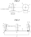
- FIG. 2 is a diagram for explaining a reference point 12 of the grindstone 8.
- the reference point 12 is the point where the convex portion 2 and the grindstone 8 come into contact when the grindstone 8 is in a reference orientation. However, when a portion in contact is not a point, this means the center of the portion of contact.
- the grindstone 8 rotates around an axis of rotation 10. When viewed from a viewpoint where the axis of rotation 10 is perpendicular to the plane of the paper (right-side diagram in FIG. 2 ), the point where the convex portion 2 and the grindstone 8 make contact is the reference point 12. When viewed from the viewpoint where the axis of rotation 10 is parallel to the plane of the paper (left-side diagram in FIG.
- the thickness of the grindstone 8 is t.
- An example of t, which is the thickness of the grindstone 8, is 10 mm to 50 mm.
- FIG. 3 is a diagram for explaining a contact angle ⁇ of the grindstone 8.
- FIG. 3 illustrates a hypothetical cross-section view where a machining trajectory 13 and the axis of rotation 10 are on the plane of the paper (the same plane).
- the machining trajectory 13 is the trajectory along which the grindstone 8 moves, as calculated by the robot motion control device 5.
- an auxiliary line 14 is drawn perpendicular to the machining trajectory 13, and the contact angle ⁇ is the angle between the auxiliary line 14 and the grindstone surface 11.
- the contact angle ⁇ is the angle between the auxiliary line 14 and the grindstone surface 11.
- trajectory start point 15 is ⁇ max.
- the contact angle ⁇ at the trajectory midpoint 16 is 0.
- the contact angle ⁇ at the trajectory end point 17 is ⁇ min, which is equal to - ⁇ max.
- An example of ⁇ max is 5°.
- the grindstone 8 is tilted by the robot motion control device 5 to have a contact angle ⁇ corresponding to displacement from the reference point 12 in one direction (x direction in the example below).
- the robot motion control device 5 controls the grinder 7 so that the axis of rotation 10 tilts according to the position where the grindstone 8 is in contact with the convex portion 2.
- the robot motion control device 5 executes variable contact angle grinding so that ⁇ changes continuously at each position along the machining trajectory 13.
- the grindstone 8 at the trajectory midpoint 16 assumes a reference orientation, and the trajectory midpoint 16 corresponds to the reference point 12 in the thickness direction of the grindstone 8.
- the grindstone 8 is tilted symmetrically around the reference point 12 like a pendulum, but this may be asymmetrical (when ⁇ min is not equal to - ⁇ max).
- variable contact angle grinding the angle at which the grindstone 8 contacts the convex portion 2 changes in various ways to promote grain dropout, resulting in constant grinding with new grains without clogging, thereby achieving high-speed grinding.
- the change pattern of ⁇ is not limited to the example illustrated in FIG. 3 , and may be adjusted in various ways according to grinding conditions such as characteristics of the workpiece 1, characteristics of the grindstone 8, rotation speed, feed rate, and pressing force. For example, by selecting a suitable ⁇ change pattern according to the type of the workpiece 1, even faster machining can be achieved. In the example illustrated in FIG. 3 , for the sake of simplicity, the machining trajectory 13 is represented as a straight line.
- variable contact angle grinding can be executed by mapping the tangent line of a curved trajectory to the straight line of the machining trajectory 13 as in the example illustrated in FIG. 3 .
- FIG. 4 and FIG. 5 illustrate Examples of recognition of the convex portion 2 by shape measurement.
- FIG. 4 illustrates logic for recognizing the convex portion 2 by height.
- the image processing device 4 sets a measurement coordinate system 18 when the three-dimensional shape measuring device 3 measures the shape of the workpiece 1.
- the three-dimensional shape measuring device 3 is a camera.
- the measurement coordinate system 18 is set so that the height direction is the z coordinate.
- Workpiece shape data 19 obtained from the measurement by the three-dimensional shape measuring device 3 is typical three-dimensional point cloud data.
- z-coordinate values in the three-dimensional point cloud data that are at least a certain value are convex portion shape data 20 (point cloud data of the convex portion 2).
- This method has a very simple recognition logic and can execute operations at high speed.
- the convex portion shape data 20 may contain inaccurate data when the height dimension of the workpiece 1 changes frequently and when there is a large variation in orientation, dimensions, and the like.
- FIG. 5 illustrates a method of obtaining the convex portion shape data 20 as a portion that does not exist in comparison CAD data 21, by three-dimensional pattern matching of the measured workpiece shape data 19 and the comparison CAD data 21.
- the comparison CAD data 21 is CAD data of the workpiece 1.
- the image processing device 4 obtains the comparison CAD data 21 from a computer or the like where the workpiece 1 was previously designed. This method is not easily affected by variation in orientation and dimension, or variation in shape, of the workpiece 1. For example, when the workpiece 1 at the time of measurement is tilted, the convex portion shape data 20 can be accurately obtained by comparison to the comparison CAD data 21 by tilting in the same way in the image processing device 4.
- the method illustrated in FIG. 4 and the method illustrated in FIG. 5 may be selected and applied according to the situation.
- the image processing device 4 may switch from the method illustrated in FIG. 4 to the method illustrated in FIG. 5 upon, for example, determining that the workpiece 1 is tilted at the time of measurement, or when the workpiece 1 has multiple types of frequently changing height dimensions.
- the image processing device 4 can increase the precision of recognition of the convex portion 2, accommodate a wide variety of the workpiece 1, and minimize the burden of calculations as much as possible.
- FIG. 6 and FIG. 7 illustrate an example of generation of the machining trajectory 13.
- FIG. 6 illustrates a method of generating the machining trajectory 13 in the x-y plane.
- the x-y plane is a plane perpendicular to the z direction, the height direction.
- the x direction corresponds to the thickness direction of the grindstone 8.
- the robot motion control device 5 acquires the convex portion shape data 20 from the image processing device 4 and generates the machining trajectory 13 for grinding the convex portion 2.
- the robot motion control device 5 generates the machining trajectory 13 in the x-y plane as follows. As illustrated in FIG. 6 , under 1), the robot motion control device 5 determines a trajectory reference line A 0 that passes through a y min position, which has the smallest y-coordinate position in the convex portion shape data 20 and is parallel to the x-coordinate axis, and a trajectory reference line A 1 that passes through y max , which has the largest y-coordinate position and is parallel to the x-coordinate axis.
- N is given by ((y max - y min )/ ⁇ p) - 2.
- the pitch ⁇ p is set according to the shape of the grindstone 8.
- the assumed depth of cut width ba is given by (D - 2ta)tan(cos -1 (1 - 2ta/D)).
- the pitch ⁇ p is 0.1ba ⁇ ⁇ p ⁇ ba.
- the assumed depth of cut ta is determined by conducting grinding experiments in advance, and a range of about 0.1 mm to 8.0 mm is suitable.
- the trajectory interval lines B i have the ends B is and B ie , which are the intersections with the outer circumference of the convex portion 2.
- B is is the intersection with the smaller x-coordinate value and B ie is the intersection with the larger x-coordinate value.
- the robot motion control device 5 sets C is , points that are larger than B is by ⁇ x in the x direction, as illustrated in FIG. 6 under 3). Further, the robot motion control device 5 sets C ie , points that are smaller than B ie by ⁇ x in the x direction.
- ⁇ x is the width of a margin portion provided in order to avoid protruding from the outer circumference of the convex portion 2 when the grindstone 8 moves along the machining trajectory 13.
- ⁇ x may be determined based on the thickness of the grindstone 8. For example, ⁇ x may be defined as t/2, with the thickness of the grindstone 8 being t.
- the robot motion control device 5 determines a grinding path p i from C ie through to C (i+1)s when i is even, as illustrated in FIG. 6 , under 4). Further, when i is odd, the robot motion control device 5 determines the grinding path p i from Cis through to C (i+1)e .
- FIG. 7 illustrates a calculation of the z-coordinate position of the machining trajectory 13.
- the machining path division number Np may be determined according to machining precision and measurement density of the convex portion shape data 20 that is point cloud data.
- the larger the machining path division number Np the higher the machining precision, but the higher the load on the robot motion control device 5, and therefore LBmax/t > Np may be used, depending on the memory resources of the robot motion control device 5 and the size of the convex portion 2.
- the z-coordinate values zg i,j are calculated by weighting the z-coordinate values of the four measurement points according to their deviations in the x-y plane. Thus, the three-dimensional coordinates of all machining trajectory control points pg i,j are determined.
- the number of measurement points used to calculate the z-coordinate value zg i,j is not limited to four. As another example, the z-coordinate value zg i,j may be determined by averaging the z-coordinate values of the closest measurement points.
- FIG. 8 and FIG. 9 illustrate examples of convex portion grinding system configurations controlled according to grinding reaction force.
- the machining trajectory 13 is defined as described above, and the grindstone 8 moves on the machining trajectory 13 to execute variable contact angle grinding, in which the contact angle ⁇ is changed according to the moving position in the x-axis direction.
- a trajectory shift may occur due to changes in the wear of the grindstone 8 and the contact angle ⁇ of the grindstone 8, and it may be necessary to correct the trajectory.
- the convex portion grinding system uses the grinding reaction force measuring device 9 to measure the reaction force and the like during grinding, and executes feedback control by changing the trajectory to achieve a pre-set target load.
- the robot motion control device 5 may correct the trajectory based on the measured grinding reaction force and control the grinder 7 so that the grindstone 8 moves along the corrected trajectory.
- the target load range may be determined, for example, by extracting the load during appropriate grinding from performance data in past grinding.
- measurement data such as the load according to the grinding reaction force measuring device 9 is fed back to the robot motion control device 5 for a planned trajectory 24, which is the machining trajectory 13 calculated as described above.
- the robot motion control device 5 controls the robot 6 in real time through a trajectory control operation 26 to adjust the actual trajectory of the grindstone 8 to be a control trajectory 25.
- the trajectory control operation 26 is considered to be an adjustment operation in the height direction (z-direction).
- the robot motion control device 5 controls the robot 6 that can move in three-dimensional directions, and therefore executes calculations for all three dimension directions, even when the adjustment operation is only in the height direction.
- the load of calculations on the robot motion control device 5 may increase.
- the grinding tool control device may comprise a first grinding tool control device and a second grinding tool control device.
- the first grinding tool control device corrects the trajectory in the height direction based on a height component of the measured grinding reaction force.
- the second grinding tool control device corrects the trajectory in a direction different from the height direction based on a component of the measured grinding reaction force in a direction different from the height direction.
- FIG. 9 illustrates a case in which the grinding tool control device comprises the first grinding tool control device and the second grinding tool control device.
- the grindstone 8 is adjusted by a single axis actuator 27 with respect to the height direction.
- An actuator control device 29, which controls the single-axis actuator 27, adjusts the height of the grindstone 8 in real time by a trajectory control operation 30 based on measured data such as the load measured by the grinding reaction force measuring device 9 that is fed back.
- the actuator control device 29 corresponds to the first grinding tool control device.
- the robot motion control device 5 corresponds to the second grinding tool control device.
- the convex portion grinding system in the configuration illustrated in FIG. 9 corrects trajectory in the height direction and trajectory in a direction different from the height direction with different grinding tool control devices. Therefore, the calculation processing is distributed, avoiding a large calculation load on a single grinding tool control device and enabling high-speed trajectory correction.
- the convex portion grinding system can automatically grind the convex portion 2 that occurs on a wide variety of products through the above configuration. Therefore, the labor of workers who previously performed grinder operations can be allocated to other tasks, thereby improving the work efficiency of production.
- a convex portion grinding method that includes the following processes may be carried out by a convex portion grinding system.
- the convex portion grinding method may include a shape measurement process in which the three-dimensional shape measuring device 3 measures the three-dimensional shape and orientation of the workpiece 1.
- the convex portion grinding method may include a convex portion detection process in which the image processing device 4 detects the convex portion 2 present on the surface of the workpiece 1 and the position and shape of the convex portion 2.
- the convex portion grinding method may include a grinding process in which the robot motion control device 5 calculates a trajectory along which the grindstone 8 moves to grind the convex portion 2 based on the measured three-dimensional shape and orientation of the workpiece 1 and the detected position and shape of the convex portion 2, and moves the grindstone 8 along the trajectory while changing the contact angle ⁇ of the grindstone 8 with respect to the convex portion 2.
- the convex portion grinding method may include an inspection process in which an inspection device inspects the surface of workpiece 1 at the location of the convex portion 2. In the inspection process, the inspection device may carry out a three-dimensional scan or the like on the surface of the workpiece 1, compare the measurement data with the comparison CAD data 21, and when the difference in the height direction is within an acceptable range, judge the workpiece as acceptable.
- the convex portion grinding method executed by the convex portion grinding system realizes a method of producing a steel product, in which a convex portion of the surface of a steel product, which is the target material, is ground.
- This method of producing a steel product can improve steel product productivity by automating grinder operations and the like that are conventionally performed by human workers.
- the image processing device 4, the robot motion control device 5, and the actuator control device 29 are each illustrated as a laptop computer, but may be another type of computer.
- the image processing device 4, the robot motion control device 5, and the actuator control device 29 may be realized by another computing device that is not a computer, as long as they can communicate with each other.
Landscapes
- Engineering & Computer Science (AREA)
- Mechanical Engineering (AREA)
- Robotics (AREA)
- Human Computer Interaction (AREA)
- Constituent Portions Of Griding Lathes, Driving, Sensing And Control (AREA)
- Grinding And Polishing Of Tertiary Curved Surfaces And Surfaces With Complex Shapes (AREA)
- Finish Polishing, Edge Sharpening, And Grinding By Specific Grinding Devices (AREA)
Abstract
Description
- The present disclosure relates to convex portion grinding systems, convex portion grinding methods, and methods of producing steel products. The present disclosure relates, in particular, to a convex portion grinding system, a convex portion grinding method, and a method of producing a steel product that remove a harmful convex portion from a surface of a steel product or the like.
- In casting products, in order to mitigate the effects of "runners" which are paths for molten metal during casting, and "shrinkage cavities" which are harmful defects that can occur inside the product, a portion such as a "riser" is added to allow a final cooling process to occur outside the product. Typically, an unwanted portion is removed by cutting, shearing, hammering, folding under their own weight, or the like during the process of removing the casting product from the mold, but a portion may remain and become a harmful "convex portion" on a casting product surface.
- Particularly in the case of producing a wide variety of products, the positions and shapes of convex portions are very diverse, and therefore convex portions are often removed by manual grinding with a grinder. Such convex portions can be as large as some tens of millimeters high, making the grinding workload burden high and making it difficult to secure necessary workers. Further, carrying out grinding at high speed is difficult when a convex portion is large or when grinding difficult-to-machine material such as high-alloy steel.
- Patent Literature (PTL) 1 proposes a method in which a robot is equipped with a grinder and grinds while applying a constant pressing force along a predetermined machining trajectory. PTL 2 proposes a method of grinding steel material at high speed by machining in a non-oxidizing gas atmosphere.
-
- PTL 1:
JP H03-178766 A - PTL 2:
JP H11-267954 A - The technology of
PTL 1 is a system that works along a pre-given trajectory and cannot automatically handle a large variety of products. - Further, the technology of
PTL 2 requires large-scale line sealing, vacuuming, and the like, resulting in very high facility and running costs. - Regarding convex portions that occur on a wide variety of products, a human worker visually observes the workpiece, presses a grinder against a convex portion position of the workpiece at a pressure that feels appropriate, and stops pressing the grinder at an appropriate time. The worker visually determines whether the convex portion remains and decides whether to regrind or terminate the operation. There was a demand for automating such work.
- In view of these circumstances, it would be helpful to provide a convex portion grinding system, a convex portion grinding method, and a method of producing a steel product that automatically grind convex portions that occur on a wide variety of products.
- The inventors conducted extensive studies on solutions to the problems described above. An analysis of the work of workers revealed that the work included (1) measuring shape and orientation of a workpiece based on visual information, (2) an operation of pressing a grindstone of a grinder against the workpiece, (3) sensing and controlling grinding reaction force and load after pressing the grindstone against the workpiece, based on tactile sense and force sense, (4) changing the grindstone angle during grinding, and (5) inspecting a remaining convex portion after grinding based on visual information.
- Based on the analysis of the work described above, as a method for automating grinding of a convex portion of a workpiece, the inventors propose a system that executes at least some of the following: (1) measuring shape and orientation of the workpiece using a three-dimensional shape measuring device, (2) recognizing a convex portion position, (3) measuring and controlling grinding reaction force and load, (4) controlling an operation of pressing against the convex portion position wherein a grindstone contact angle can be changed during grinding, and (5) inspecting a remaining convex portion after grinding and determining whether to regrind.
- [1] A convex portion grinding system according to an embodiment of the present disclosure comprises:
- a shape measuring device configured to measure three-dimensional shape and orientation of a target material;
- a convex portion detection device configured to detect a convex portion on a surface of the target material and recognize position and shape of the convex portion;
- a grinding device including a grinding tool configured to grind the convex portion; and
- a grinding tool control device configured to calculate a trajectory along which the grinding tool moves based on the measured three-dimensional shape and orientation of the target material and the detected position and shape of the convex portion, and configured to control the grinding device so that the grinding tool moves along the trajectory while changing the contact angle of the grinding tool with respect to the convex portion.
- [2] The convex portion grinding system according to [1], as an embodiment of the present disclosure, further comprising
- a grinding reaction force measuring device configured to measure a grinding reaction force that the grinding tool receives from the target material, wherein
- the grinding tool control device is configured to correct the trajectory based on the measured grinding reaction force and control the grinding device so that the grinding tool moves along the corrected trajectory.
- [3] The convex portion grinding system according to [2], as an embodiment of the present disclosure, wherein
- the grinding tool control device comprises a first grinding tool control device and a second grinding tool control device,
- the first grinding tool control device is configured to correct the trajectory in the height direction based on a height component of the measured grinding reaction force, and
- the second grinding tool control device is configured to correct the trajectory in a direction different from the height direction based on a component of the measured grinding reaction force in a direction different from the height direction.
- [4] The convex portion grinding system according to any one of [1] to [3], as an embodiment of the present disclosure, further comprising
an inspection device configured to inspect a surface of the target material at a position of the convex portion after the convex portion is ground. - [5] The convex portion grinding system according to any one of [1] to [4], as an embodiment of the present disclosure, wherein
- the grinding tool is a grindstone configured to rotate around an axis of rotation, and
- the grinding tool control device is configured to control the grinding device so that the axis of rotation is tilted according to the position where the grindstone comes into contact with the convex portion.
- [6] A convex portion grinding method according to an embodiment of the present disclosure comprises:
- a shape measuring process of measuring three-dimensional shape and orientation of a target material;
- a convex portion detection process of detecting a convex portion on a surface of the target material and detecting position and shape of the convex portion; and
- a grinding process of calculating a trajectory along which a grinding tool moves to grind the convex portion based on the measured three-dimensional shape and orientation of the target material and the detected position and shape of the convex portion, and grinding the convex portion by moving the grinding tool along the trajectory while changing the contact angle of the grinding tool with respect to the convex portion.
- [7] The convex portion grinding method according to [6], as an embodiment of the present disclosure, wherein
the grinding process further comprises measuring a grinding reaction force that the grinding tool receives from the target material, correcting the trajectory based on the measured grinding reaction force, and moving the grinding tool along the corrected trajectory to grind the convex portion. - [8] The convex portion grinding method according to [6] or [7], as an embodiment of the present disclosure, further comprising,
after the grinding process, an inspection process of inspecting a surface of the target material at the position of the convex portion. - [9] A method of producing a steel product according to an embodiment of the present disclosure, the method comprising
grinding a convex portion on a surface of a steel product, which is the target material, using the convex portion grinding method according to any one of [6] to [8]. - According to the present disclosure, a convex portion grinding system, a convex portion grinding method, and a method of producing a steel product can be provided that automatically grind convex portions that occur on a wide variety of products.
- In the accompanying drawings:
-
FIG. 1 is a schematic diagram of a convex portion grinding system according to an embodiment; -
FIG. 2 is a diagram for explaining a reference point of a grindstone; -
FIG. 3 is a diagram for explaining a contact angle of the grindstone; -
FIG. 4 is a diagram illustrating an example of shape measurement and convex portion extraction; -
FIG. 5 is a diagram illustrating another example of shape measurement and convex portion extraction; -
FIG. 6 is a diagram illustrating an example of a method of generating a machining trajectory in the x-y plane; -
FIG. 7 is a diagram illustrating calculation of the z-coordinate position of the machining trajectory; -
FIG. 8 is a diagram illustrating an example configuration of a convex portion grinding system controlled according to grinding reaction force; and -
FIG. 9 is a diagram illustrating another example configuration of the convex portion grinding system controlled according to the grinding reaction force. - A convex portion grinding system, a convex portion grinding method, and a method of producing a steel product according to an embodiment of the present disclosure are described below with reference to the drawings.
-
FIG. 1 illustrates an example of a schematic diagram of the convex portion grinding system according to the present embodiment. Aconvex portion 2 exists on the surface of aworkpiece 1, which is an example of a target material. A three-dimensionalshape measuring device 3, which is an example of a shape measuring device, measures the three-dimensional shape and orientation of theworkpiece 1. As examples of the three-dimensionalshape measuring device 3, a camera that carries out a three-dimensional scan of theworkpiece 1, a shape laser sensor, or the like may be used. Based on a measurement result of the three-dimensionalshape measuring device 3, animage processing device 4, which is an example of a convex portion detection device, detects theconvex portion 2 on the surface of theworkpiece 1 and recognizes the position and shape of theconvex portion 2. A robotmotion control device 5, which is an example of a grinding tool control device, executes an inverse kinematics calculation based on the measured three-dimensional shape and orientation of theworkpiece 1 and the detected position and shape of theconvex portion 2 to calculate the trajectory of agrindstone 8 as it moves to be pressed against the position of theconvex portion 2. Here, thegrindstone 8 is a grinding tool for grinding theconvex portion 2, and is included in a grinder 7, which is an example of a grinding device. The grinder 7 is moved by arobot 6 that has multiple joints. Therobot 6 is controlled by a robotmotion control device 5. That is, the robotmotion control device 5 can, via therobot 6, control the grinder 7 so that thegrindstone 8 moves along the calculated trajectory. Further, the calculated trajectory along which thegrindstone 8 moves also corresponds to a motion trajectory of therobot 6. - The
robot 6 operates based on the generated motion trajectory, and thegrindstone 8 comes into contact with theworkpiece 1 and theconvex portion 2 to grind theconvex portion 2. At this time, a grinding reactionforce measuring device 9 measures a grinding reaction force that thegrindstone 8 receives from theworkpiece 1. The robotmotion control device 5 controls the motion of therobot 6 to press thegrindstone 8 against or move thegrindstone 8 away from theworkpiece 1 and theconvex portion 2 so that the measured grinding reaction force becomes a target grinding reaction force. After grinding theconvex portion 2 for a certain time or after a defined grinding amount is reached, the robotmotion control device 5 causes the three-dimensional measuring device to measure the shape of theworkpiece 1 after grinding. The robotmotion control device 5 determines whether a remaining portion of theconvex portion 2 has been detected by theimage processing device 4, and when theconvex portion 2 remains, carries out grinding again. The robotmotion control device 5 terminates grinding when theconvex portion 2 does not remain. The convex portion grinding system may include an inspection device that inspects the surface of theworkpiece 1 at the location of theconvex portion 2 after theconvex portion 2 has been ground. At this time, the robotmotion control device 5 may carry out grinding again or terminate grinding based on the inspection result from the inspection device. The inspection device may comprise the three-dimensionalshape measuring device 3 and theimage processing device 4. - One of the features of the convex portion grinding system according to the present embodiment is that the robot
motion control device 5 controls the grinder 7 so that thegrindstone 8 moves along the calculated trajectory while changing the contact angle of thegrindstone 8 with respect to theconvex portion 2. The grinding carried out by the convex portion grinding system according to the present embodiment while changing the contact angle of thegrindstone 8 may be referred to as "variable contact angle grinding". -
FIG. 2 is a diagram for explaining areference point 12 of thegrindstone 8. Thereference point 12 is the point where theconvex portion 2 and thegrindstone 8 come into contact when thegrindstone 8 is in a reference orientation. However, when a portion in contact is not a point, this means the center of the portion of contact. According to the present embodiment, thegrindstone 8 rotates around an axis ofrotation 10. When viewed from a viewpoint where the axis ofrotation 10 is perpendicular to the plane of the paper (right-side diagram inFIG. 2 ), the point where theconvex portion 2 and thegrindstone 8 make contact is thereference point 12. When viewed from the viewpoint where the axis ofrotation 10 is parallel to the plane of the paper (left-side diagram inFIG. 2 ), the thickness of thegrindstone 8 is t. The point where theconvex portion 2 and thegrindstone 8 come into contact at t/2 from thegrindstone surface 11, the end surface of thegrindstone 8, is the reference point 12 (thereference point 12 in the thickness direction of the grindstone 8). An example of t, which is the thickness of thegrindstone 8, is 10 mm to 50 mm. -
FIG. 3 is a diagram for explaining a contact angle θ of thegrindstone 8.FIG. 3 illustrates a hypothetical cross-section view where amachining trajectory 13 and the axis ofrotation 10 are on the plane of the paper (the same plane). Themachining trajectory 13 is the trajectory along which thegrindstone 8 moves, as calculated by the robotmotion control device 5. InFIG. 3 , anauxiliary line 14 is drawn perpendicular to themachining trajectory 13, and the contact angle θ is the angle between theauxiliary line 14 and thegrindstone surface 11. In the example inFIG. 3 , the point where thegrindstone 8 started moving, the point where thegrindstone 8 advanced to the midpoint of themachining trajectory 13, and the point where thegrindstone 8 finished moving are indicated as trajectory startpoint 15,trajectory midpoint 16, andtrajectory end point 17, respectively. The contact angle θ at thetrajectory start point 15 is θmax. The contact angle θ at thetrajectory midpoint 16 is 0. The contact angle θ at thetrajectory end point 17 is θmin, which is equal to -θmax. An example of θmax is 5°. Thegrindstone 8 is tilted by the robotmotion control device 5 to have a contact angle θ corresponding to displacement from thereference point 12 in one direction (x direction in the example below). In other words, the robotmotion control device 5 controls the grinder 7 so that the axis ofrotation 10 tilts according to the position where thegrindstone 8 is in contact with theconvex portion 2. The robotmotion control device 5 executes variable contact angle grinding so that θ changes continuously at each position along themachining trajectory 13. In the example illustrated inFIG. 3 , thegrindstone 8 at thetrajectory midpoint 16 assumes a reference orientation, and thetrajectory midpoint 16 corresponds to thereference point 12 in the thickness direction of thegrindstone 8. In the example illustrated inFIG. 3 , thegrindstone 8 is tilted symmetrically around thereference point 12 like a pendulum, but this may be asymmetrical (when θmin is not equal to -θmax). - In variable contact angle grinding, the angle at which the
grindstone 8 contacts theconvex portion 2 changes in various ways to promote grain dropout, resulting in constant grinding with new grains without clogging, thereby achieving high-speed grinding. The change pattern of θ is not limited to the example illustrated inFIG. 3 , and may be adjusted in various ways according to grinding conditions such as characteristics of theworkpiece 1, characteristics of thegrindstone 8, rotation speed, feed rate, and pressing force. For example, by selecting a suitable θ change pattern according to the type of theworkpiece 1, even faster machining can be achieved. In the example illustrated inFIG. 3 , for the sake of simplicity, themachining trajectory 13 is represented as a straight line. Although themachining trajectory 13 is often a complex curve that matches the shape of theconvex portion 2, variable contact angle grinding can be executed by mapping the tangent line of a curved trajectory to the straight line of themachining trajectory 13 as in the example illustrated inFIG. 3 . -
FIG. 4 and FIG. 5 illustrate Examples of recognition of theconvex portion 2 by shape measurement.FIG. 4 illustrates logic for recognizing theconvex portion 2 by height. First, theimage processing device 4 sets a measurement coordinatesystem 18 when the three-dimensionalshape measuring device 3 measures the shape of theworkpiece 1. The three-dimensionalshape measuring device 3 is a camera. The measurement coordinatesystem 18 is set so that the height direction is the z coordinate.Workpiece shape data 19 obtained from the measurement by the three-dimensionalshape measuring device 3 is typical three-dimensional point cloud data. z-coordinate values in the three-dimensional point cloud data that are at least a certain value are convex portion shape data 20 (point cloud data of the convex portion 2). This method has a very simple recognition logic and can execute operations at high speed. However, the convexportion shape data 20 may contain inaccurate data when the height dimension of theworkpiece 1 changes frequently and when there is a large variation in orientation, dimensions, and the like. -
FIG. 5 illustrates a method of obtaining the convexportion shape data 20 as a portion that does not exist incomparison CAD data 21, by three-dimensional pattern matching of the measuredworkpiece shape data 19 and thecomparison CAD data 21. Thecomparison CAD data 21 is CAD data of theworkpiece 1. Theimage processing device 4 obtains thecomparison CAD data 21 from a computer or the like where theworkpiece 1 was previously designed. This method is not easily affected by variation in orientation and dimension, or variation in shape, of theworkpiece 1. For example, when theworkpiece 1 at the time of measurement is tilted, the convexportion shape data 20 can be accurately obtained by comparison to thecomparison CAD data 21 by tilting in the same way in theimage processing device 4. - Here, the method illustrated in
FIG. 4 and the method illustrated inFIG. 5 may be selected and applied according to the situation. Theimage processing device 4 may switch from the method illustrated inFIG. 4 to the method illustrated inFIG. 5 upon, for example, determining that theworkpiece 1 is tilted at the time of measurement, or when theworkpiece 1 has multiple types of frequently changing height dimensions. By selecting the method according to the situation, theimage processing device 4 can increase the precision of recognition of theconvex portion 2, accommodate a wide variety of theworkpiece 1, and minimize the burden of calculations as much as possible. -
FIG. 6 andFIG. 7 illustrate an example of generation of themachining trajectory 13.FIG. 6 illustrates a method of generating themachining trajectory 13 in the x-y plane. The x-y plane is a plane perpendicular to the z direction, the height direction. In the example illustrated inFIG. 6 , the x direction corresponds to the thickness direction of thegrindstone 8. - The robot
motion control device 5 acquires the convexportion shape data 20 from theimage processing device 4 and generates themachining trajectory 13 for grinding theconvex portion 2. The robotmotion control device 5 generates themachining trajectory 13 in the x-y plane as follows. As illustrated inFIG. 6 , under 1), the robotmotion control device 5 determines a trajectory reference line A0 that passes through a ymin position, which has the smallest y-coordinate position in the convexportion shape data 20 and is parallel to the x-coordinate axis, and a trajectory reference line A1 that passes through ymax, which has the largest y-coordinate position and is parallel to the x-coordinate axis. - The robot
motion control device 5 determines trajectory interval lines Bi (i = 0 to N) that are drawn at equal intervals at pitch Δp from the trajectory reference line A0 and are parallel to the x-coordinate axis, as illustrated inFIG. 6 under 2). Here, N is given by ((ymax - ymin)/Δp) - 2. - The pitch Δp is set according to the shape of the
grindstone 8. When the diameter of thegrindstone 8 is D and the assumed depth of cut is ta, the assumed depth of cut width ba is given by (D - 2ta)tan(cos-1(1 - 2ta/D)). In this case, the pitch Δp is 0.1ba ≤ Δp ≤ ba. Here, the assumed depth of cut ta is determined by conducting grinding experiments in advance, and a range of about 0.1 mm to 8.0 mm is suitable. - The trajectory interval lines Bi have the ends Bis and Bie, which are the intersections with the outer circumference of the
convex portion 2. Here, Bis is the intersection with the smaller x-coordinate value and Bie is the intersection with the larger x-coordinate value. - The robot
motion control device 5 sets Cis, points that are larger than Bis by Δx in the x direction, as illustrated inFIG. 6 under 3). Further, the robotmotion control device 5 sets Cie, points that are smaller than Bie by Δx in the x direction. Δx is the width of a margin portion provided in order to avoid protruding from the outer circumference of theconvex portion 2 when thegrindstone 8 moves along themachining trajectory 13. Δx may be determined based on the thickness of thegrindstone 8. For example, Δx may be defined as t/2, with the thickness of thegrindstone 8 being t. - The robot
motion control device 5 determines a grinding path pi from Cie through to C(i+1)s when i is even, as illustrated inFIG. 6 , under 4). Further, when i is odd, the robotmotion control device 5 determines the grinding path pi from Cis through to C(i+1)e. -
FIG. 7 illustrates a calculation of the z-coordinate position of themachining trajectory 13. The robotmotion control device 5 divides each grinding path pi by a machining path division number Np, and sets each division point as a machining path control point pgij (j = 0 to Np). The machining path division number Np may be determined according to machining precision and measurement density of the convexportion shape data 20 that is point cloud data. - As an example, the machining path division number Np is suitable in a range where LBmax is the largest dimension (maximum value) among the x-direction dimensions LBi = √(Bic - Bis)2 (i = 0 to N) of the
convex portion 2, and LBmax/t ≤ Np. However, the larger the machining path division number Np, the higher the machining precision, but the higher the load on the robotmotion control device 5, and therefore LBmax/t > Np may be used, depending on the memory resources of the robotmotion control device 5 and the size of theconvex portion 2. - The robot
motion control device 5 determines machining trajectory control points pgi,j from the four closest measurement points (four point cloud data). For example, as illustrated inFIG. 7 , when the four closest measurement points are Pmk = (xk, yk, zk), Pmk+1 = (xk+1, yk+1, zk+1), Pmk+2 = (xk+2, yk+2, zk+2), and Pmk+3 = (xk+3, yk+3, zk+3), the z coordinate value of pgi,j, zgi,j is expressed by the following.
- The z-coordinate values zgi,j are calculated by weighting the z-coordinate values of the four measurement points according to their deviations in the x-y plane. Thus, the three-dimensional coordinates of all machining trajectory control points pgi,j are determined. The number of measurement points used to calculate the z-coordinate value zgi,j is not limited to four. As another example, the z-coordinate value zgi,j may be determined by averaging the z-coordinate values of the closest measurement points.
-
FIG. 8 and FIG. 9 illustrate examples of convex portion grinding system configurations controlled according to grinding reaction force. Themachining trajectory 13 is defined as described above, and thegrindstone 8 moves on themachining trajectory 13 to execute variable contact angle grinding, in which the contact angle θ is changed according to the moving position in the x-axis direction. Here, in actual grinding, a trajectory shift may occur due to changes in the wear of thegrindstone 8 and the contact angle θ of thegrindstone 8, and it may be necessary to correct the trajectory. The convex portion grinding system according to the present embodiment uses the grinding reactionforce measuring device 9 to measure the reaction force and the like during grinding, and executes feedback control by changing the trajectory to achieve a pre-set target load. For example, the robotmotion control device 5 may correct the trajectory based on the measured grinding reaction force and control the grinder 7 so that thegrindstone 8 moves along the corrected trajectory. Here, the target load range may be determined, for example, by extracting the load during appropriate grinding from performance data in past grinding. - For example, as illustrated in
FIG. 8 , measurement data such as the load according to the grinding reactionforce measuring device 9 is fed back to the robotmotion control device 5 for a plannedtrajectory 24, which is themachining trajectory 13 calculated as described above. The robotmotion control device 5 controls therobot 6 in real time through atrajectory control operation 26 to adjust the actual trajectory of thegrindstone 8 to be acontrol trajectory 25. - According to the present embodiment, the
trajectory control operation 26 is considered to be an adjustment operation in the height direction (z-direction). However, the robotmotion control device 5 controls therobot 6 that can move in three-dimensional directions, and therefore executes calculations for all three dimension directions, even when the adjustment operation is only in the height direction. As a result, the load of calculations on the robotmotion control device 5 may increase. Accordingly, the grinding tool control device may comprise a first grinding tool control device and a second grinding tool control device. The first grinding tool control device corrects the trajectory in the height direction based on a height component of the measured grinding reaction force. The second grinding tool control device corrects the trajectory in a direction different from the height direction based on a component of the measured grinding reaction force in a direction different from the height direction. -
FIG. 9 illustrates a case in which the grinding tool control device comprises the first grinding tool control device and the second grinding tool control device. Thegrindstone 8 is adjusted by asingle axis actuator 27 with respect to the height direction. Anactuator control device 29, which controls the single-axis actuator 27, adjusts the height of thegrindstone 8 in real time by atrajectory control operation 30 based on measured data such as the load measured by the grinding reactionforce measuring device 9 that is fed back. Theactuator control device 29 corresponds to the first grinding tool control device. Further, the robotmotion control device 5 corresponds to the second grinding tool control device. The convex portion grinding system in the configuration illustrated inFIG. 9 corrects trajectory in the height direction and trajectory in a direction different from the height direction with different grinding tool control devices. Therefore, the calculation processing is distributed, avoiding a large calculation load on a single grinding tool control device and enabling high-speed trajectory correction. - As described above, the convex portion grinding system can automatically grind the
convex portion 2 that occurs on a wide variety of products through the above configuration. Therefore, the labor of workers who previously performed grinder operations can be allocated to other tasks, thereby improving the work efficiency of production. - Although embodiments of the present disclosure have been described based on the drawings and examples, it should be noted that a person skilled in the art may make variations and modifications based on the present disclosure. Therefore, it should be noted that such variations and modifications are included within the scope of the present disclosure. For example, functions and the like included in each component and step may be rearranged, and a plurality of components and steps may be combined into one or divided, as long as no logical inconsistency results. Although embodiments of the present disclosure have been described with a focus on devices, an embodiment of the present disclosure may also be realized as a method that includes steps executed by components of devices. An embodiment of the present disclosure may be realized as a method, a program executed by a processor provided to a device, or a storage medium on which the program is stored. The scope of the present disclosure should be understood to include these examples.
- For example, a convex portion grinding method that includes the following processes may be carried out by a convex portion grinding system. The convex portion grinding method may include a shape measurement process in which the three-dimensional
shape measuring device 3 measures the three-dimensional shape and orientation of theworkpiece 1. The convex portion grinding method may include a convex portion detection process in which theimage processing device 4 detects theconvex portion 2 present on the surface of theworkpiece 1 and the position and shape of theconvex portion 2. The convex portion grinding method may include a grinding process in which the robotmotion control device 5 calculates a trajectory along which thegrindstone 8 moves to grind theconvex portion 2 based on the measured three-dimensional shape and orientation of theworkpiece 1 and the detected position and shape of theconvex portion 2, and moves thegrindstone 8 along the trajectory while changing the contact angle θ of thegrindstone 8 with respect to theconvex portion 2. The convex portion grinding method may include an inspection process in which an inspection device inspects the surface ofworkpiece 1 at the location of theconvex portion 2. In the inspection process, the inspection device may carry out a three-dimensional scan or the like on the surface of theworkpiece 1, compare the measurement data with thecomparison CAD data 21, and when the difference in the height direction is within an acceptable range, judge the workpiece as acceptable. - For example, the convex portion grinding method executed by the convex portion grinding system realizes a method of producing a steel product, in which a convex portion of the surface of a steel product, which is the target material, is ground. This method of producing a steel product can improve steel product productivity by automating grinder operations and the like that are conventionally performed by human workers.
- Further, according to the embodiments described above, the
image processing device 4, the robotmotion control device 5, and theactuator control device 29 are each illustrated as a laptop computer, but may be another type of computer. Theimage processing device 4, the robotmotion control device 5, and theactuator control device 29 may be realized by another computing device that is not a computer, as long as they can communicate with each other. -
- 1 workpiece (example of target material)
- 2 convex portion
- 3 three-dimensional shape measuring device (example of shape measuring device)
- 4 image processing device (example of convex portion detection device)
- 5 robot motion control device (example of grinding tool control device)
- 6 robot
- 7 grinder (example of grinding device)
- 8 grindstone (example of grinding tool)
- 9 grinding reaction force measuring device
- 10 axis of rotation
- 11 grindstone surface
- 12 reference point
- 13 machining trajectory
- 14 auxiliary line
- 15 trajectory start point
- 16 trajectory midpoint
- 17 trajectory end point
- 18 measurement coordinate system
- 19 workpiece shape data
- 20 convex portion shape data
- 21 comparison CAD data
- 24 planned trajectory
- 25 control trajectory
- 26 trajectory control operation
- 27 single-axis actuator
- 29 actuator control device
- 30 trajectory control operation
Claims (9)
- A convex portion grinding system comprising:a shape measuring device configured to measure three-dimensional shape and orientation of a target material;a convex portion detection device configured to detect a convex portion on a surface of the target material and recognize position and shape of the convex portion;a grinding device including a grinding tool configured to grind the convex portion; anda grinding tool control device configured to calculate a trajectory along which the grinding tool moves based on the measured three-dimensional shape and orientation of the target material and the detected position and shape of the convex portion, and configured to control the grinding device so that the grinding tool moves along the trajectory while changing the contact angle of the grinding tool with respect to the convex portion.
- The convex portion grinding system according to claim 1, further comprising a grinding reaction force measuring device configured to measure a grinding reaction force that the grinding tool receives from the target material, wherein
the grinding tool control device is configured to correct the trajectory based on the measured grinding reaction force and control the grinding device so that the grinding tool moves along the corrected trajectory. - The convex portion grinding system according to claim 2, wherein the grinding tool control device comprises a first grinding tool control device and a second grinding tool control device,the first grinding tool control device is configured to correct the trajectory in the height direction based on a height component of the measured grinding reaction force, andthe second grinding tool control device is configured to correct the trajectory in a direction different from the height direction based on a component of the measured grinding reaction force in a direction different from the height direction.
- The convex portion grinding system according to any one of claims 1 to 3, further comprising an inspection device configured to inspect a surface of the target material at a position of the convex portion after the convex portion is ground.
- The convex portion grinding system according to any one of claims 1 to 4, wherein the grinding tool is a grindstone configured to rotate around an axis of rotation, and
the grinding tool control device is configured to control the grinding device so that the axis of rotation is tilted according to the position where the grindstone comes into contact with the convex portion. - A convex portion grinding method comprising:a shape measuring process of measuring three-dimensional shape and orientation of a target material;a convex portion detection process of detecting a convex portion on a surface of the target material and detecting position and shape of the convex portion; anda grinding process of calculating a trajectory along which a grinding tool moves to grind the convex portion based on the measured three-dimensional shape and orientation of the target material and the detected position and shape of the convex portion, and grinding the convex portion by moving the grinding tool along the trajectory while changing the contact angle of the grinding tool with respect to the convex portion.
- The convex portion grinding method according to claim 6, wherein the grinding process further comprises measuring a grinding reaction force that the grinding tool receives from the target material, correcting the trajectory based on the measured grinding reaction force, and moving the grinding tool along the corrected trajectory to grind the convex portion.
- The convex portion grinding method according to claim 6 or 7, further comprising, after the grinding process, an inspection process of inspecting a surface of the target material at the position of the convex portion.
- A method of producing a steel product, the method comprising grinding a convex portion on a surface of a steel product, which is the target material, using the convex portion grinding method according to any one of claims 6 to 8.
Applications Claiming Priority (2)
| Application Number | Priority Date | Filing Date | Title |
|---|---|---|---|
| JP2022163537 | 2022-10-11 | ||
| PCT/JP2023/033779 WO2024080081A1 (en) | 2022-10-11 | 2023-09-15 | Projection polishing system, projection polishing method, and method for manufacturing steel product |
Publications (2)
| Publication Number | Publication Date |
|---|---|
| EP4566754A1 true EP4566754A1 (en) | 2025-06-11 |
| EP4566754A4 EP4566754A4 (en) | 2025-12-10 |
Family
ID=90669115
Family Applications (1)
| Application Number | Title | Priority Date | Filing Date |
|---|---|---|---|
| EP23877087.9A Pending EP4566754A4 (en) | 2022-10-11 | 2023-09-15 | Projection polishing system, projection polishing process and method for manufacturing a steel product |
Country Status (6)
| Country | Link |
|---|---|
| US (1) | US20260084317A1 (en) |
| EP (1) | EP4566754A4 (en) |
| JP (1) | JP7613614B2 (en) |
| KR (1) | KR20250050095A (en) |
| CN (1) | CN119947854A (en) |
| WO (1) | WO2024080081A1 (en) |
Family Cites Families (12)
| Publication number | Priority date | Publication date | Assignee | Title |
|---|---|---|---|---|
| JP2676793B2 (en) * | 1988-06-30 | 1997-11-17 | トヨタ自動車株式会社 | Copy control robot |
| JPH07276206A (en) * | 1994-04-12 | 1995-10-24 | Daido Steel Co Ltd | Work surface automatic processing equipment |
| JP3670700B2 (en) * | 1994-04-27 | 2005-07-13 | 株式会社日立製作所 | Robot mechanism control method |
| JPH11267954A (en) | 1998-03-20 | 1999-10-05 | Kenichi Ishikawa | Grinding method |
| JP4033377B2 (en) | 2001-12-11 | 2008-01-16 | 日立マクセル株式会社 | Non-aqueous electrolyte battery |
| JP2004050326A (en) * | 2002-07-18 | 2004-02-19 | Mitsubishi Heavy Ind Ltd | Three-dimensional curved surface grinding device |
| JP4216557B2 (en) * | 2002-09-30 | 2009-01-28 | 株式会社エーエスエー・システムズ | Polishing apparatus and polishing method |
| JP5127524B2 (en) * | 2008-03-25 | 2013-01-23 | 株式会社東芝 | 3D curved surface processing apparatus and 3D curved surface processing method |
| JP6323744B2 (en) * | 2014-01-27 | 2018-05-16 | 株式会社Ihi | Polishing robot and its control method |
| JP2018062044A (en) * | 2016-10-14 | 2018-04-19 | 株式会社和井田製作所 | Workpiece swivel table, profile grinder including the same, workpiece process method by profile grinder |
| JP6977640B2 (en) * | 2018-03-19 | 2021-12-08 | 株式会社Ihi | Processing equipment and processing method |
| CN116323099A (en) * | 2020-10-14 | 2023-06-23 | 杰富意钢铁株式会社 | Scar Grinding System, Scar Grinding Method, and Manufacturing Method of Steel Products Using the Same |
-
2023
- 2023-09-15 US US19/110,423 patent/US20260084317A1/en active Pending
- 2023-09-15 CN CN202380069455.6A patent/CN119947854A/en active Pending
- 2023-09-15 KR KR1020257008641A patent/KR20250050095A/en active Pending
- 2023-09-15 WO PCT/JP2023/033779 patent/WO2024080081A1/en not_active Ceased
- 2023-09-15 EP EP23877087.9A patent/EP4566754A4/en active Pending
- 2023-09-15 JP JP2023576225A patent/JP7613614B2/en active Active
Also Published As
| Publication number | Publication date |
|---|---|
| CN119947854A (en) | 2025-05-06 |
| EP4566754A4 (en) | 2025-12-10 |
| WO2024080081A1 (en) | 2024-04-18 |
| JP7613614B2 (en) | 2025-01-15 |
| US20260084317A1 (en) | 2026-03-26 |
| JPWO2024080081A1 (en) | 2024-04-18 |
| KR20250050095A (en) | 2025-04-14 |
Similar Documents
| Publication | Publication Date | Title |
|---|---|---|
| CA2725277C (en) | Method for cutting a material layer by means of a cutting beam | |
| US12377521B2 (en) | Autonomous modification of waterjet cutting systems | |
| CN107529334B (en) | Method and device for machining a tool by removing material | |
| US6772039B2 (en) | NC program generating method, NC program generating apparatus, computer memory product, and computer program product | |
| KR102800666B1 (en) | Defect grinding system, defect grinding method and method for manufacturing steel products using the same | |
| CN119871091B (en) | A high-precision multi-axis machining composite CNC machine tool control system | |
| CN102452042B (en) | Machining method and device | |
| EP0627283B1 (en) | Method of controlling a grinder robot | |
| JP3378834B2 (en) | Finishing method and equipment | |
| EP4566754A1 (en) | Projection polishing system, projection polishing method, and method for manufacturing steel product | |
| Jung et al. | Chip load prediction in ball-end milling | |
| JP3972920B2 (en) | NC machine tool and correction processing method | |
| CN106681278A (en) | Cutter and workpiece instantaneous contact contour extraction method during five-axis side-milling machining | |
| JPH07136903A (en) | Free curved surface processing method | |
| CN109041572B (en) | Wire electric discharge machine and wire electric discharge machining method | |
| Chang et al. | A new mathematical method of modeling parts in virtual CNC lathing and its application on accurate tool path generation | |
| Wan et al. | 5-axis grinding path generation for free-form surface based on plane instantaneous grinding engagements | |
| Li et al. | A study on variable curvature trajectory planning method for robotic weld grinding based on line-structured light vision guidance | |
| CN108107836A (en) | A kind of method for establishing the mismachining tolerance model M EM for free form surface | |
| Shchegol’kov | Shaping of noncylindrical helical chip-channel surfaces in complex mills | |
| CN120816027A (en) | A processing method and system for ensuring the dimensional accuracy of hole seat stop | |
| CN119589500A (en) | A RMI intelligent processing method, system, electronic device and storage medium |
Legal Events
| Date | Code | Title | Description |
|---|---|---|---|
| STAA | Information on the status of an ep patent application or granted ep patent |
Free format text: STATUS: THE INTERNATIONAL PUBLICATION HAS BEEN MADE |
|
| PUAI | Public reference made under article 153(3) epc to a published international application that has entered the european phase |
Free format text: ORIGINAL CODE: 0009012 |
|
| STAA | Information on the status of an ep patent application or granted ep patent |
Free format text: STATUS: REQUEST FOR EXAMINATION WAS MADE |
|
| 17P | Request for examination filed |
Effective date: 20250305 |
|
| AK | Designated contracting states |
Kind code of ref document: A1 Designated state(s): AL AT BE BG CH CY CZ DE DK EE ES FI FR GB GR HR HU IE IS IT LI LT LU LV MC ME MK MT NL NO PL PT RO RS SE SI SK SM TR |
|
| A4 | Supplementary search report drawn up and despatched |
Effective date: 20251106 |
|
| RIC1 | Information provided on ipc code assigned before grant |
Ipc: B24B 49/12 20060101AFI20251031BHEP Ipc: B24B 27/00 20060101ALI20251031BHEP Ipc: B24B 49/16 20060101ALI20251031BHEP Ipc: B25J 13/08 20060101ALI20251031BHEP Ipc: B24B 19/26 20060101ALI20251031BHEP |
|
| DAV | Request for validation of the european patent (deleted) | ||
| DAX | Request for extension of the european patent (deleted) |