EP4566742A1 - Machine tool, chuck gripping force detection method, and chuck fastening amount setting method - Google Patents
Machine tool, chuck gripping force detection method, and chuck fastening amount setting method Download PDFInfo
- Publication number
- EP4566742A1 EP4566742A1 EP23849893.5A EP23849893A EP4566742A1 EP 4566742 A1 EP4566742 A1 EP 4566742A1 EP 23849893 A EP23849893 A EP 23849893A EP 4566742 A1 EP4566742 A1 EP 4566742A1
- Authority
- EP
- European Patent Office
- Prior art keywords
- chuck
- time
- open
- workpiece
- closed state
- Prior art date
- Legal status (The legal status is an assumption and is not a legal conclusion. Google has not performed a legal analysis and makes no representation as to the accuracy of the status listed.)
- Pending
Links
Images






Classifications
-
- B—PERFORMING OPERATIONS; TRANSPORTING
- B23—MACHINE TOOLS; METAL-WORKING NOT OTHERWISE PROVIDED FOR
- B23B—TURNING; BORING
- B23B31/00—Chucks; Expansion mandrels; Adaptations thereof for remote control
- B23B31/02—Chucks
- B23B31/24—Chucks characterised by features relating primarily to remote control of the gripping means
- B23B31/28—Chucks characterised by features relating primarily to remote control of the gripping means using electric or magnetic means in the chuck
-
- B—PERFORMING OPERATIONS; TRANSPORTING
- B23—MACHINE TOOLS; METAL-WORKING NOT OTHERWISE PROVIDED FOR
- B23B—TURNING; BORING
- B23B31/00—Chucks; Expansion mandrels; Adaptations thereof for remote control
- B23B31/02—Chucks
- B23B31/10—Chucks characterised by the retaining or gripping devices or their immediate operating means
-
- B—PERFORMING OPERATIONS; TRANSPORTING
- B23—MACHINE TOOLS; METAL-WORKING NOT OTHERWISE PROVIDED FOR
- B23B—TURNING; BORING
- B23B25/00—Accessories or auxiliary equipment for turning-machines
- B23B25/06—Measuring, gauging, or adjusting equipment on turning-machines for setting-on, feeding, controlling, or monitoring the cutting tools or work
-
- B—PERFORMING OPERATIONS; TRANSPORTING
- B23—MACHINE TOOLS; METAL-WORKING NOT OTHERWISE PROVIDED FOR
- B23Q—DETAILS, COMPONENTS, OR ACCESSORIES FOR MACHINE TOOLS, e.g. ARRANGEMENTS FOR COPYING OR CONTROLLING; MACHINE TOOLS IN GENERAL CHARACTERISED BY THE CONSTRUCTION OF PARTICULAR DETAILS OR COMPONENTS; COMBINATIONS OR ASSOCIATIONS OF METAL-WORKING MACHINES, NOT DIRECTED TO A PARTICULAR RESULT
- B23Q17/00—Arrangements for observing, indicating or measuring on machine tools
-
- B—PERFORMING OPERATIONS; TRANSPORTING
- B23—MACHINE TOOLS; METAL-WORKING NOT OTHERWISE PROVIDED FOR
- B23Q—DETAILS, COMPONENTS, OR ACCESSORIES FOR MACHINE TOOLS, e.g. ARRANGEMENTS FOR COPYING OR CONTROLLING; MACHINE TOOLS IN GENERAL CHARACTERISED BY THE CONSTRUCTION OF PARTICULAR DETAILS OR COMPONENTS; COMBINATIONS OR ASSOCIATIONS OF METAL-WORKING MACHINES, NOT DIRECTED TO A PARTICULAR RESULT
- B23Q17/00—Arrangements for observing, indicating or measuring on machine tools
- B23Q17/002—Arrangements for observing, indicating or measuring on machine tools for indicating or measuring the holding action of work or tool holders
-
- B—PERFORMING OPERATIONS; TRANSPORTING
- B23—MACHINE TOOLS; METAL-WORKING NOT OTHERWISE PROVIDED FOR
- B23Q—DETAILS, COMPONENTS, OR ACCESSORIES FOR MACHINE TOOLS, e.g. ARRANGEMENTS FOR COPYING OR CONTROLLING; MACHINE TOOLS IN GENERAL CHARACTERISED BY THE CONSTRUCTION OF PARTICULAR DETAILS OR COMPONENTS; COMBINATIONS OR ASSOCIATIONS OF METAL-WORKING MACHINES, NOT DIRECTED TO A PARTICULAR RESULT
- B23Q17/00—Arrangements for observing, indicating or measuring on machine tools
- B23Q17/002—Arrangements for observing, indicating or measuring on machine tools for indicating or measuring the holding action of work or tool holders
- B23Q17/003—Arrangements for observing, indicating or measuring on machine tools for indicating or measuring the holding action of work or tool holders by measuring a position
-
- B—PERFORMING OPERATIONS; TRANSPORTING
- B23—MACHINE TOOLS; METAL-WORKING NOT OTHERWISE PROVIDED FOR
- B23Q—DETAILS, COMPONENTS, OR ACCESSORIES FOR MACHINE TOOLS, e.g. ARRANGEMENTS FOR COPYING OR CONTROLLING; MACHINE TOOLS IN GENERAL CHARACTERISED BY THE CONSTRUCTION OF PARTICULAR DETAILS OR COMPONENTS; COMBINATIONS OR ASSOCIATIONS OF METAL-WORKING MACHINES, NOT DIRECTED TO A PARTICULAR RESULT
- B23Q17/00—Arrangements for observing, indicating or measuring on machine tools
- B23Q17/002—Arrangements for observing, indicating or measuring on machine tools for indicating or measuring the holding action of work or tool holders
- B23Q17/005—Arrangements for observing, indicating or measuring on machine tools for indicating or measuring the holding action of work or tool holders by measuring a force, a pressure or a deformation
-
- B—PERFORMING OPERATIONS; TRANSPORTING
- B23—MACHINE TOOLS; METAL-WORKING NOT OTHERWISE PROVIDED FOR
- B23Q—DETAILS, COMPONENTS, OR ACCESSORIES FOR MACHINE TOOLS, e.g. ARRANGEMENTS FOR COPYING OR CONTROLLING; MACHINE TOOLS IN GENERAL CHARACTERISED BY THE CONSTRUCTION OF PARTICULAR DETAILS OR COMPONENTS; COMBINATIONS OR ASSOCIATIONS OF METAL-WORKING MACHINES, NOT DIRECTED TO A PARTICULAR RESULT
- B23Q17/00—Arrangements for observing, indicating or measuring on machine tools
- B23Q17/006—Arrangements for observing, indicating or measuring on machine tools for indicating the presence of a work or tool in its holder
-
- B—PERFORMING OPERATIONS; TRANSPORTING
- B23—MACHINE TOOLS; METAL-WORKING NOT OTHERWISE PROVIDED FOR
- B23B—TURNING; BORING
- B23B2231/00—Details of chucks, toolholder shanks or tool shanks
- B23B2231/26—Detection of clamping
Definitions
- the present invention relates to a method for detecting the holding force of a chuck in a machine tool.
- PTL 1 discloses a method for controlling the holding force of a chuck by controlling the rotation angle of the spindle motor, based on a predetermined relationship between an amount of tightening corresponding to the rotation of the spindle motor after the chuck has contacted the workpiece until a preset holding force is generated, and the holding force of the chuck.
- the holding force of a chuck is not easy to measure directly, and the common approach is to determine the force from an amount of control of the mechanism that causes the chuck to operate, as described above.
- the relationship between a control amount and the holding force is not necessarily consistent in many cases due to various factors such as ongoing chuck wear and changes in lubrication conditions.
- An object of the present invention is to provide a technique that enables correct control of the holding force of a chuck.
- a machine tool includes:
- a chuck holding force detection method is a method for detecting a holding force applied to a workpiece by a chuck in a spindle of a machine tool in a case where the chuck holds the workpiece, including:
- a chuck tightening amount setting method is a method for setting a tightening amount applied to a workpiece by a chuck in a spindle of a machine tool in a case where the chuck holds the workpiece, including:
- the present invention enables correct control of the holding force of a chuck.
- Fig. 1 is a schematic diagram illustrating the configuration of a machine tool 1 according to one embodiment of the present invention.
- the machine tool 1 shown in Fig. 1 is a type known as an automatic lathe that performs a cutting (turning) operation on a workpiece W to be machined, which is a long rod member, for example, by rotating the workpiece and bringing a cutting tool (machining tool) into contact with the workpiece.
- the guide bush mentioned above (not shown) is provided at the distal end opening of the workpiece holding hole in the spindle, for example, and keeps the orientation of the workpiece W near the opening of the workpiece holding hole.
- the structure for supporting the workpiece W using the guide bush may be configured separately from the spindle unit 100.
- the chuck and the chuck sleeve which are not shown in Fig. 1 , are configured to join axially via a tapered surface.
- the chuck sleeve is joined from behind to the chuck, which is restrained from axial movement.
- the chuck sleeve is moved in the axial direction by receiving a force applied from an air cylinder that is not shown in Fig. 1 , causing a component of force toward the axial center to be applied to the chuck. This force contracts the chuck and causes the slits of the chuck to close.
- the chuck clamps the workpiece W in this way.
- the machine tool 1 includes a control unit 200 configured by a computer including a processor such as a CPU (Central Processing Unit) and a memory.
- the control unit 200 controls various operations of various units making up the machine tool 1, including the spindle unit 100, the tool head 300, a workpiece feeder (not shown), an actuator 60 to be described later, a display unit 70, and so on.
- a processor such as a CPU (Central Processing Unit)
- the control unit 200 controls various operations of various units making up the machine tool 1, including the spindle unit 100, the tool head 300, a workpiece feeder (not shown), an actuator 60 to be described later, a display unit 70, and so on.
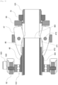
- Fig. 2 and Fig. 3 are schematic cross-sectional views each illustrating the basic configuration around the spindle 101 to a greater scale.
- Fig. 2 shows the configuration of various parts in a state where a collet chuck 41 is closed, i.e., when a workpiece W is clamped.
- Fig. 3 shows the configuration of various parts in a state where the collet chuck 41 is opened, i.e., when the workpiece W is attachable to and removable from the spindle 101.
- Fig. 4 and Fig. 5 are schematic cross-sectional views each illustrating the configuration around chuck claws 47, a bobbin 48, and a chuck holder 50 to a greater scale.
- Fig. 1 shows the configuration of various parts in a state where a collet chuck 41 is closed, i.e., when a workpiece W is clamped.
- Fig. 3 shows the configuration of various parts in a state where the collet chuck 41 is opened,
- FIG. 4 shows the configuration of various parts in a state where the chuck claws 47 are in a closed orientation, i.e., when the collet chuck 41 is in a closed state and clamping the workpiece W.
- Fig. 5 shows the configuration of various parts in a state where the chuck claws 47 are opened, i.e., when the workpiece W is attachable to and removable from the collet chuck 41.
- the spindle 101 is assembled to the headstock 102 such as to be rotatable via bearing assemblies 121, 122, and 123.
- the collet chuck 41 is attached to the distal end in the axial direction of the spindle 101.
- the collet chuck 41 includes a hollow tubular body 411 that can receive the workpiece W inside, and a clamping portion 412 provided at the distal end in the direction of the center axis line L (longitudinal direction) of the tubular body 411.
- the clamping portion 412 has a so-called slit structure, which allows it to elastically change its inside diameter about the center axis line L1.
- the clamping portion 412 is formed with slits 413 extending a predetermined length in the axial direction from an end face at the distal end toward the rear end.
- the slits 413 are formed by cutting off the clamping portion 412 at plural locations radially around the center axis line L and circumferentially at equal intervals, for example, around the center axis line L. Between these plural slits 413 are formed strips 414 that are capable of displacing radially about the center axis line L1.
- the strips 414 are each configured as a plate spring that can elastically deform in the radial direction with their base ends as the support point.
- the strips 414 each have a concavely curved inner surface facing toward the center axis line L1, and together form a substantially cylindrical workpiece clamping surface 415 in the clamping portion 412.
- the outer surface of each strip 414 includes an inclined surface tilted relative to the axial direction. These inclined surfaces together form a tapered force receiving surface 416 that gradually increases in diameter towards the distal end in the axial direction.
- a shoulder surface 417 extending perpendicularly to the center axis line L1 is formed at the more distal end in the axial direction than the force receiving surface 416 formed by the strips 414.
- the plurality of strips 414 each deflects elastically when an external radially inward force is applied via the force receiving surface 416, causing the workpiece clamping surface 415 to reduce in diameter until the surface makes tight contact with the workpiece W, thus firmly and securely holding the workpiece W.
- the strips 414 each resiliently rebound, thereby increasing the diameter of the workpiece clamping surface 415 so that the workpiece W is released from the clamping portion 412.
- a cap nut 42 is attached to the distal end of the workpiece holding hole of the spindle 101.
- the cap nut 42 includes a locking surface 421, which is an end face oriented toward the rear end in the axial direction, making contact with the shoulder surface 417 of the collet chuck 41 in the axial direction.
- the chuck sleeve 43 as a second actuating member, is assembled in the workpiece holding hole of the spindle 101 such as to hold the collet chuck 41 between itself and the cap nut 42.
- the chuck sleeve 43 is a hollow tubular member that can receive therein the workpiece W and the collet chuck 41 that surrounds the workpiece.
- the inner surface of the chuck sleeve 43 includes a force imparting surface 431 that acts on the force receiving surface 416 of the collet chuck 41.
- a compression coil spring 44 is assembled in the chuck sleeve 43 as a resilient member that imparts an axial biasing force to the collet chuck 41.
- the chuck sleeve 43 has a spring receiving surface 432, so that the compression coil spring 44 is axially compressed between the spring receiving surface 432 and the axial rear end face of the collet chuck 41. This biasing force of the compression coil spring 44 brings the shoulder surface 417 of the collet chuck 41 into contact with the locking surface 421, and presses the collet chuck 41 axially against the cap nut 42.
- the force imparting surface 431 is a tapered surface that gradually increases in diameter towards the axial distal end and that faces and makes contact with the force receiving surface 416 both in the axial direction along the center axis line L1 and the radial direction about the center axis line L1.
- the force imparting surface 431 imparting a radially inward actuating force to the force receiving surface 416 causes the clamping portion 412 of the collet chuck 41 to perform the operation of holding the workpiece W as described above.
- a chuck opening/closing sleeve 45 and a balancing sleeve 46 are mounted at the axial rear end of the chuck sleeve 43.
- the chuck sleeve 43 and these chuck opening/closing sleeve 45 and balancing sleeve 46 are serially aligned in the axial direction in this order and axially engaged.
- These sleeves are configured to be integrally displaceable in the axial direction as the second actuating member.
- the balancing sleeve 46 has an actuated surface 461 at the axial rear end for receiving an actuating force.
- the spindle 101 is provided with chuck claws 47 as a first actuating member for imparting an actuating force to the actuated surface 461 of the balancing sleeve 46.
- the chuck claws 47 are provided in plurality, at equal intervals around the center axis line L1, for example.
- Each chuck claw 47 has an actuating portion 471 that makes contact with the actuated surface 461 in the axial direction.
- Each chuck claw is rotatable relative to the spindle 101 about a rotary shaft 472 along a tangential line of an imaginary circle about the center axis line L1.
- the chuck holder 50 collectively supports the plurality of chuck claws 47, i.e., the chuck claws are assembled to the spindle 101 via the chuck holder 50.
- the chuck claws 47 rotate to be able to assume a closed orientation with the actuating portions 471 advanced axially forward and an open orientation with the actuating portions 471 retracted axially rearward.
- the chuck claws 47 include an actuated portion 473 that receives the driving force for changing the orientations as described above.
- the spindle 101 is provided with the bobbin 48, which is mounted on a cylindrical wall of the spindle 101 such as to be axially displaceable, as a linear actuator that imparts a driving force to the actuated portion 473. More specifically, the bobbin 48 is configured as a part of the bearing assembly 123 that is axially displaceable relative to the spindle 101.
- the bearing assembly 123 is axially shifted relative to the spindle 101 by a driving force from the actuator 60 as a driving means.
- the bobbin 48 is configured to be movable by an axial displacement of the bearing assembly 123 between an actuating position where it causes the chuck claws 47 to assume the closed orientation and an actuated position where it causes the chuck claws 47 to assume the open orientation.
- the bobbin 48 includes an actuating portion 481 that is a substantially conical outer circumferential surface gradually reducing in diameter towards the axial rear end.
- the chuck claws 47 are on the bobbin 48 with the actuated portions 473 being in contact with the actuating portion 481.
- the chuck claws 47 rotate as they slide onto the bobbin 48 and assume the closed orientation.
- the actuated portions 473 are away from the actuating portion 481 and in contact with an outer circumferential surface of the spindle 101, i.e., the chuck claws 47 are not in contact with the bobbin 48.
- the chuck claws 47 rotate as they come down from the bobbin 48 and assume the open orientation.
- the actuator 60 includes an air cylinder 61, and an arm 62 that connects a rod 610 of the air cylinder 61 and the bearing assembly 123.
- the arm 62 is mounted to the headstock 102 such as to be rotatable about a rotary shaft 622, is rotatably connected to the rod 610 via a rotary shaft 621, and is rotatably connected to the bearing assembly 123 via a rotary shaft 623.
- the rod 610 of the air cylinder 61 reciprocates in the directions along the center axis line L, and the arm 62 rotates about the rotary shaft 622 as the rod 610 reciprocates.
- the rotary shaft 623 that connects the bearing assembly 123 and the arm 62 is configured to be displaceable in the longitudinal direction of the arm 62, so that the rotary shaft shifts in the direction along the center axis line L while also shifting in the longitudinal direction of the arm as the arm 62 rotates.
- the bearing assembly 123 axially shifts on the spindle 101 to cause a change in the axial relative position of the bobbin 48 to the chuck claws 47.
- the actuating portions 471 push the actuated surface 461 axially forward, causing the balancing sleeve 46, the chuck opening/closing sleeve 45, and the chuck sleeve 43 to be pushed axially forward sequentially.
- a radially inward force is applied from the force imparting surface 431 of the chuck sleeve 43 to the force receiving surface 416 of the collet chuck 41, causing an increase in the holding force of the collet chuck 41 on the workpiece W, and bringing the collet chuck into the closed state in which it firmly and securely clamps the workpiece W.
- the actuating portions 471 axially move back, allowing the chuck sleeve 43, the chuck opening/closing sleeve 45, and the balancing sleeve 46 to be pushed axially backward sequentially by the biasing force of the compression coil spring 44.
- the radially inward force from the force imparting surface 431 of the chuck sleeve 43 to the force receiving surface 416 of the collet chuck 41 is removed, causing a decrease in the holding force of the collet chuck 41 on the workpiece W, and bringing the collet chuck 41 into the open state in which it allows the workpiece W to be removed.
- the air cylinder 61 is provided with a chuck open position sensor 71 and a chuck close position sensor 72.
- the chuck open position sensor 71 is configured to respond when the rod 610 strokes to a contracted position ( Fig. 2 ) where it has moved the bobbin 48 to the activating position.
- the chuck close position sensor 72 is configured to respond when the rod 610 strokes to an extended position ( Fig. 3 ) where it has moved the bobbin 48 to the non-activating position.
- the sensors 71 and 72 may be optical sensors, for example, detecting markings on the rod 610. Any other conventional or known sensors can be used as desired.
- the chuck open position sensor 71 outputs an ON signal when the rod 610 is in the contracted position (or passes a predetermined contraction reference position), and outputs an OFF signal when the rod 610 strokes out of the contracted position (or does not reach the contraction reference position).
- the chuck close position sensor 72 outputs an ON signal when the rod 610 is in the extended position (or passes a predetermined extension reference position), and outputs an OFF signal when the rod 610 strokes out of the extended position (or does not reach the extension reference position). Consequently, during a stroke of the rod 610, there is a transition period in which neither the chuck open position sensor 71 nor the chuck close position sensor 72 respond (both output the OFF signal). This transition period varies in length in accordance with the amount of tightening of the adjustment nut 51.
- Fig. 6 is a timing chart showing the response time of each of the chuck open position sensor 71 and the chuck close position sensor 72 in response to a chuck close signal issued by the control unit 200 to the actuator 60.
- the actuator 60 causes the collet chuck 41 to perform a closing operation from the open state to the closed state
- the period from when the control unit 200 has issued a control signal to the actuator 60 to perform the closing operation to when the output of the chuck open position sensor 71 switches from ON to OFF shall be referred to as period A (first time).
- the period from when the control unit 200 has issued a control signal to the actuator 60 to perform the closing operation to when the output of the chuck close position sensor 72 switches from OFF to ON shall be referred to as period B (second time).
- the transition period is period B - A (time difference).
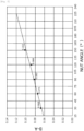
- Fig. 7 is a graph showing an example of the changes in the period B - A corresponding to the change in the tightening amount (nut angle) of the adjustment nut 51.
- the period B - A was plotted as 0.068, 0.075, 0.082, 0.088, and 0.102, respectively corresponding to the nut angles 30°, 60°, 90°, 120°, and 150°. The results indicate that the tightening amount of the adjustment nut 51 and the period B - A have a substantially linear relationship.
- actuators that drive the spindle unit 100 and the tool head 300, and the actuator 60 for the opening and closing of the collet chuck 41, so that control signals are sent from the control unit 200 to these components.
- the CPU 201 controls the machine tool 1 and performs various information processing operations.
- An operating system (OS) and various programs and tables are stored in the ROM 202 or RAM 203 as storage means. Various constituent parts are controlled through the execution of stored programs.
- the control unit 200 thus implements the functions that serve predetermined purposes.
- the control unit 200 may be a single computer, or a plurality of computers coordinated to work together.
- the holding force acquisition unit 212 acquires the holding force applied to the workpiece W by the collet chuck 41 in the closed state based on the period B - A as described above.
- the holding force is acquired on the basis of a correlation between the period B - A described above and the tightening amount of the nut. Namely, there is a linear relationship between the period B - A described above and the tightening amount of the nut (adjustment setting of the adjustment nut 51), and there is a linear relationship between the tightening amount of the nut and the holding force applied to the workpiece W by the collet chuck 41 in the closed state.
- a holding force corresponding to a tightening amount of the nut can be acquired by calculation using the above-described linear relationship based on multiple actual measurements, which may be obtained experimentally, for example, by detecting discrete values in kilogram force (kgf) as a unit, for example, using a torque sensor on the collet chuck 41.
- the holding force can be presented to the user as specific values, or as incremental levels of the holding force, with each level representing a preset range of nut tightening settings.
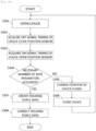
- Fig. 10 is a flowchart for creating holding force correlation data by the holding force acquisition unit.
- the holding force correlation data is created during a preparation or setup process prior to machining of actual products.
- the workpiece W used in this process can be a spare workpiece W rather than the actual product.
- Fig. 11 is a flowchart for detecting the holding force of the chuck using the holding force data obtained by the process of Fig. 10 .
- Holding force detection may be performed during the setting process prior to machining of actual products similarly to the process of Fig. 10 , or during the machining of actual products.
- the control unit 200 issues a chuck close signal to the actuator 60, to cause the collet chuck 41 to close and hold the workpiece W (S201).
- the adjustment nut 51 may be preset to an angle with a certain margin in this preparatory step as compared to the angle during the actual machining.
- the tightening amount of the adjustment nut 51 here is a provisional setting (first tightening amount) for obtaining an optimal setting (second tightening amount) for an optimal holding force of the collet chuck 41.
- the period A and the period B are acquired (S202 and S203).
- the period A is the period from when the control signal for the closing operation was issued to when the chuck open position sensor 71 detects that the collet chuck 41 is no longer in the open position.
- the period B is the period from when the control signal for the closing operation was issued to when the chuck close position sensor 72 detects that the collet chuck 41 has assumed the closed state.
- the period B - A obtained from the periods A and B is compared with the correlation between the period and the holding force (holding force data) acquired by the process of Fig. 10 , or calculated on the basis of this correlation, to determine a corresponding holding force (S204).
- the obtained holding force is informed to the user via the output unit 82 as a notification means (S205).
- the user notified of the holding force by the steps described above can readjust the adjustment nut 51 to achieve a desired holding force if necessary on the basis of the notified holding force.
- the correlation between the nut adjustment setting and the holding force may also be displayed.
- a necessary adjustment amount of the nut (second tightening amount) for achieving the desired holding force may be determined at S204 and presented to the user at S205.
- the holding force correction unit 213 corrects the correlation between the obtained period B - A and the holding force (holding force data).
- the period A is basically when no load is applied (when load does not vary largely) during the chuck operation, and therefore the sensor detection time is substantially constant regardless of the tightening amount of the adjustment nut 51.
- the detection time can vary by the influence of changes in the air supply pressure of the air cylinder 61, and lubrication conditions between the chuck claws 47 and the bobbin 48. For example, if the air supply pressure of the air cylinder 61 has dropped from the standard 0.5 MPa to 0.4 MPa, the time A will be longer, which makes the period B longer, too.
- a delay (period C - D) in the sensor detection times when the chuck performs an opening operation caused by changes over time is obtained to determine a time lag (coefficient) to be used for the correction of the delay (period B - A) in the closing operation.
- Fig. 12 is a timing chart showing the response time of each of the chuck open position sensor 71 and the chuck close position sensor 72 in response to a chuck open signal issued by the control unit 200 to the actuator 60.
- the actuator 60 causes the collet chuck 41 to perform the closing operation from the closed state to the open state
- the period from when the control unit 200 has issued a control signal to the actuator 60 to perform the opening operation to when the output of the chuck close position sensor 72 switches from ON to OFF shall be referred to as period C (third time).
- the period from when the control unit 200 has issued the control signal to the actuator 60 to perform the opening operation to when the output of the chuck open position sensor 71 switches from OFF to ON shall be referred to as period D (fourth time).
- the transition period is period D - C (time difference).
- This transition period D - C may fluctuate due to changes in machine behavior over time as described above.
- a coefficient (time lag) for correcting the holding force data can be obtained. Correcting the holding force data using this coefficient will enable determination of a more suitable holding force.
- Fig. 13 is a flowchart for correcting the holding force correlation data by the holding force acquisition unit. This process is performed, after the creation of a standard set of holding force correlation data in the initial new state of the machine, every time the number of operations of the machine reaches a predetermined value, to update the holding force correlation data.
- the control unit 200 issues a chuck open signal to the actuator 60, to cause the collet chuck 41 to open and release the workpiece W (S301). Then, the period C and the period D are acquired (S302 and S303).
- the period C is the period from when the control signal for the opening operation was issued to when the chuck close position sensor 72 detects that the collet chuck 41 is no longer in the closed position.
- the period D is the period from when the control signal for the opening operation was issued to when the chuck open position sensor 71 detects that the collet chuck 41 has assumed the open state.
- the control unit 200 stores the acquired periods C and D, and the period D - C obtained from these, in the storage means.
- the latest holding force data (C', D') thus obtained by the process described above is compared with the initially obtained standard holding force data (C, D), to determine a time lag (coefficient) and to correct the holding force data corresponding to the period B - C (S308).
- the adjustment setting of the adjustment nut 51 (which corresponds to the holding force of the collet chuck 41) based on the time difference in sensor detection times enables an optimal holding force to be set, regardless of the reference point setting. Namely, the holding force of the chuck is correctly controlled, so that the machining precision can be improved.
Landscapes
- Engineering & Computer Science (AREA)
- Mechanical Engineering (AREA)
- Gripping On Spindles (AREA)
- Machine Tool Sensing Apparatuses (AREA)
Abstract
Provided is technology which enables suitable control of a chuck gripping force. In this machine tool comprising a main shaft provided with a chuck for gripping a workpiece, when an open/close mechanism has performed a closing operation on the chuck such that the chuck enters a closed state from an open state, a gripping force of the chuck on the workpiece in the closed state is acquired on the basis of the magnitude of a difference between a first time taken from when a control unit emits a control signal for the closing operation to the open/close mechanism to when a sensor detects that the chuck is no longer in the open state, and a second time taken from when the control unit emits a control signal in an open/close period to when the sensor detects that the chuck has entered the closed state.
Description
- The present invention relates to a method for detecting the holding force of a chuck in a machine tool.
- In a machine tool, a workpiece is machined by rotating a spindle that holds the workpiece and by moving back and forth a machining tool relative to the rotating workpiece. A chuck (jaws) properly holding the workpiece is a key element in determining machining precision.
PTL 1 discloses a method for controlling the holding force of a chuck by controlling the rotation angle of the spindle motor, based on a predetermined relationship between an amount of tightening corresponding to the rotation of the spindle motor after the chuck has contacted the workpiece until a preset holding force is generated, and the holding force of the chuck. - [PTL 1]
Japanese Patent Application Publication No. 2001-096409 - The holding force of a chuck is not easy to measure directly, and the common approach is to determine the force from an amount of control of the mechanism that causes the chuck to operate, as described above. However, the relationship between a control amount and the holding force is not necessarily consistent in many cases due to various factors such as ongoing chuck wear and changes in lubrication conditions.
- An object of the present invention is to provide a technique that enables correct control of the holding force of a chuck.
- To achieve the above object, a machine tool according to the present invention includes:
- a spindle including a chuck configured to hold a workpiece;
- an open/close mechanism configured to operate the chuck to assume either a closed state in which the chuck holds the workpiece or an open state in which the chuck allows the workpiece to be removed;
- a sensor configured to detect whether or not the chuck is in the closed state, and whether or not the chuck is in the open state, respectively; and
- a control unit configured to control the open/close mechanism;
- wherein the machine tool includes an acquisition means configured to acquire a holding force applied to the workpiece by the chuck in the closed state based on a difference between a first time and a second time, the first time being, in a case where the open/close mechanism causes the chuck to perform a closing operation from the open state to the closed state, a time from when the control unit issues a control signal to the open/close mechanism to perform the closing operation to when the sensor detects that the chuck is no longer in the open state, and the second time being a time from when the control unit issues the control signal to the open/close period to when the sensor detects that the chuck has assumed the closed state.
- To achieve the above object, a chuck holding force detection method according to the present invention is
a method for detecting a holding force applied to a workpiece by a chuck in a spindle of a machine tool in a case where the chuck holds the workpiece, including: - a first step in which an open/close mechanism causes the chuck to perform a closing operation, from an open state in which the chuck allows a workpiece to be removed to a closed state in which the chuck holds a workpiece;
- a second step in which a first time and a second time are acquired, the first time being a time from when a control unit issues a control signal to the open/close mechanism for the closing operation in the first step to when a sensor detects that the chuck is no longer in the open state, and the second time being a time from when the control unit issues the control signal to the open/close mechanism to when the sensor detects that the chuck has assumed the closed state; and
- a third step in which the holding force is obtained on the basis of a correlation between a difference between the first time and the second time, a tightening amount adjusted by an adjustment mechanism applied to the workpiece by the chuck in the closed state, and the holding force.
- To achieve the above object, a chuck tightening amount setting method according to the present invention is
a method for setting a tightening amount applied to a workpiece by a chuck in a spindle of a machine tool in a case where the chuck holds the workpiece, including: - a first step in which, with the chuck in a closed state in which the chuck holds a workpiece, and with a tightening amount applied to the workpiece by the chuck in the closed state being adjusted by an adjustment mechanism to a first tightening amount, an open/close mechanism causes the chuck to perform a closing operation, from an open state in which the chuck allows a workpiece to be removed to the closed state,
- a second step in which a first time and a second time are acquired, the first time being a time from when a control unit issues a control signal to the open/close mechanism for the closing operation in the first step to when a sensor detects that the chuck is no longer in the open state, and the second time being a time from when the control unit issues the control signal to the open/close mechanism to when the sensor detects that the chuck has assumed the closed state;
- a third step in which a second tightening amount that enables the holding force to be set to a desired value is obtained on the basis of a correlation between a difference between the first time and the second time, a tightening amount adjusted by the adjustment mechanism applied to the workpiece by the chuck in the closed state, and a holding force applied to the workpiece by the chuck in the closed state; and
- a fourth step in which the tightening amount is adjusted by the adjustment mechanism to the second tightening amount obtained in the third step.
- The present invention enables correct control of the holding force of a chuck.
-
- [
Fig. 1 ]
Fig. 1 is a schematic diagram of a machine tool including a workpiece collecting device according to an embodiment of the present invention. - [
Fig. 2 ]
Fig. 2 is a schematic cross-sectional view of the basic configuration around a spindle. - [
Fig. 3 ]
Fig. 3 is a schematic cross-sectional view of the basic configuration around the spindle. - [
Fig. 4 ]
Fig. 4 is a schematic cross-sectional view of the configuration around chuck claws, a bobbin, and a chuck holder. - [
Fig. 5 ]
Fig. 5 is a schematic cross-sectional view of the configuration around the chuck claws, the bobbin, and the chuck holder. - [
Fig. 6 ]
Fig. 6 is a timing chart of a chuck close signal and sensor response times. - [
Fig. 7 ]
Fig. 7 is a graph showing a relationship between the amount of tightening (nut angle) of an adjustment nut and period B - A. - [
Fig. 8 ]
Fig. 8 is a schematic block diagram illustrating one example of the configuration of the machine tool according to this embodiment. - [
Fig. 9 ]
Fig. 9 is a diagram illustrating one example of the functional configuration of a control unit. - [
Fig. 10 ]
Fig. 10 is a flowchart for creating holding force correlation data. - [
Fig. 11 ]
Fig. 11 is a flowchart for detecting a holding force. - [
Fig. 12 ]
Fig. 12 is a timing chart of a chuck open signal and sensor response times. - [
Fig. 13 ]
Fig. 13 is a flowchart for correcting the holding force. - Preferred embodiments of the present invention will be described below with reference to the drawings. Note, the embodiments described below merely illustrate preferred configurations of the present invention and are not intended to limit the scope of the present invention to these configurations. Unless otherwise particularly specified, the hardware and software configurations of various devices, production conditions, and the sizes, materials, shapes, and relative arrangement of constituent components in the following description are not intended to limit the scope of the present invention to these examples. The same constituent elements are basically given the same reference numerals to omit repeated description thereof.
-
Fig. 1 is a schematic diagram illustrating the configuration of amachine tool 1 according to one embodiment of the present invention. Themachine tool 1 shown inFig. 1 is a type known as an automatic lathe that performs a cutting (turning) operation on a workpiece W to be machined, which is a long rod member, for example, by rotating the workpiece and bringing a cutting tool (machining tool) into contact with the workpiece. - The
machine tool 1 generally includes aspindle unit 100 set on abase 2, and atool head 300. Thespindle unit 100 includes aspindle 101. The direction of the rotation axis of thespindle 101 shall be referred to as Z-axis direction. Of the directions perpendicular to the axial direction, the direction parallel to the vertical direction shall be referred to as X-axis direction, and the direction parallel to the horizontal direction shall be referred to as Y-axis direction.Fig. 1 is a schematic diagram of the configuration of themachine tool 1 viewed in the Y-axis direction. - The
spindle unit 100 includes aheadstock 102 that rotatably supports thespindle 101, and adrive unit 103 for moving theheadstock 102 in the Z-axis direction on thebase 2. A ball screw drive system, for example, made up of a motor as the drive power source, a ball screw, guide rails, etc., can be employed as the drive unit. Thespindle unit 100 may include a drive unit that moves theheadstock 102 not only in the Z-axis direction but also in the Y-axis or X-axis direction. Theheadstock 102 includes a built-in motor (not shown), for example, and is configured to rotate thespindle 101 by the rotary driving force of the motor. - The
spindle 101 has a hollow structure with a workpiece holding hole for holding or clamping a workpiece W. The spindle includes a chuck, a chuck sleeve, a guide bush, and so on for clamping a workpiece W (with matching axial centers and such as to restrict axial movement). The workpiece W is inserted from the opening at the rear end of the workpiece holding hole in the spindle, fed in the axial direction through the workpiece holding hole, and clamped by the chuck in a predetermined inserted position. A portion of the workpiece W protruding from the opening at the distal end of the workpiece holding hole in the spindle is subjected to a turning operation performed by acutting tool 301 held on thetool head 300. The guide bush mentioned above (not shown) is provided at the distal end opening of the workpiece holding hole in the spindle, for example, and keeps the orientation of the workpiece W near the opening of the workpiece holding hole. The structure for supporting the workpiece W using the guide bush may be configured separately from thespindle unit 100. - The chuck and the chuck sleeve, which are not shown in
Fig. 1 , are configured to join axially via a tapered surface. As will be described in more detail later, the chuck sleeve is joined from behind to the chuck, which is restrained from axial movement. The chuck sleeve is moved in the axial direction by receiving a force applied from an air cylinder that is not shown inFig. 1 , causing a component of force toward the axial center to be applied to the chuck. This force contracts the chuck and causes the slits of the chuck to close. The chuck clamps the workpiece W in this way. - The
tool head 300 includes a plurality of cuttingtools 301 that are prepared to be selected according to the intended type of machining. Thetool head 300 is configured to advance and retract in the X-axis direction relative to the workpiece W by a drive system that is not shown. A desired cutting (turning) operation is carried out to the workpiece W by bringing a selectedcutting tool 301 into contact with the workpiece W. - The
machine tool 1 includes acontrol unit 200 configured by a computer including a processor such as a CPU (Central Processing Unit) and a memory. Thecontrol unit 200 controls various operations of various units making up themachine tool 1, including thespindle unit 100, thetool head 300, a workpiece feeder (not shown), anactuator 60 to be described later, a display unit 70, and so on. -
Fig. 2 andFig. 3 are schematic cross-sectional views each illustrating the basic configuration around thespindle 101 to a greater scale.Fig. 2 shows the configuration of various parts in a state where acollet chuck 41 is closed, i.e., when a workpiece W is clamped.Fig. 3 shows the configuration of various parts in a state where thecollet chuck 41 is opened, i.e., when the workpiece W is attachable to and removable from thespindle 101.Fig. 4 andFig. 5 are schematic cross-sectional views each illustrating the configuration aroundchuck claws 47, abobbin 48, and achuck holder 50 to a greater scale.Fig. 4 shows the configuration of various parts in a state where thechuck claws 47 are in a closed orientation, i.e., when thecollet chuck 41 is in a closed state and clamping the workpiece W.Fig. 5 shows the configuration of various parts in a state where thechuck claws 47 are opened, i.e., when the workpiece W is attachable to and removable from thecollet chuck 41. - As shown in
Fig. 2 andFig. 3 , thespindle 101 is assembled to theheadstock 102 such as to be rotatable via bearingassemblies collet chuck 41 is attached to the distal end in the axial direction of thespindle 101. Thecollet chuck 41 includes a hollowtubular body 411 that can receive the workpiece W inside, and a clampingportion 412 provided at the distal end in the direction of the center axis line L (longitudinal direction) of thetubular body 411. - The clamping
portion 412 has a so-called slit structure, which allows it to elastically change its inside diameter about the center axis line L1. Namely, the clampingportion 412 is formed withslits 413 extending a predetermined length in the axial direction from an end face at the distal end toward the rear end. Theslits 413 are formed by cutting off the clampingportion 412 at plural locations radially around the center axis line L and circumferentially at equal intervals, for example, around the center axis line L. Between theseplural slits 413 are formedstrips 414 that are capable of displacing radially about the center axis line L1. Thestrips 414 are each configured as a plate spring that can elastically deform in the radial direction with their base ends as the support point. - The
strips 414 each have a concavely curved inner surface facing toward the center axis line L1, and together form a substantially cylindricalworkpiece clamping surface 415 in the clampingportion 412. The outer surface of eachstrip 414 includes an inclined surface tilted relative to the axial direction. These inclined surfaces together form a taperedforce receiving surface 416 that gradually increases in diameter towards the distal end in the axial direction. Ashoulder surface 417 extending perpendicularly to the center axis line L1 is formed at the more distal end in the axial direction than theforce receiving surface 416 formed by thestrips 414. - The plurality of
strips 414 each deflects elastically when an external radially inward force is applied via theforce receiving surface 416, causing theworkpiece clamping surface 415 to reduce in diameter until the surface makes tight contact with the workpiece W, thus firmly and securely holding the workpiece W. When the radial pressure on the clampingportion 412 is removed, thestrips 414 each resiliently rebound, thereby increasing the diameter of theworkpiece clamping surface 415 so that the workpiece W is released from the clampingportion 412. - A
cap nut 42 is attached to the distal end of the workpiece holding hole of thespindle 101. Thecap nut 42 includes a lockingsurface 421, which is an end face oriented toward the rear end in the axial direction, making contact with theshoulder surface 417 of thecollet chuck 41 in the axial direction. Thechuck sleeve 43, as a second actuating member, is assembled in the workpiece holding hole of thespindle 101 such as to hold thecollet chuck 41 between itself and thecap nut 42. - The
chuck sleeve 43 is a hollow tubular member that can receive therein the workpiece W and thecollet chuck 41 that surrounds the workpiece. The inner surface of thechuck sleeve 43 includes aforce imparting surface 431 that acts on theforce receiving surface 416 of thecollet chuck 41. Acompression coil spring 44 is assembled in thechuck sleeve 43 as a resilient member that imparts an axial biasing force to thecollet chuck 41. Thechuck sleeve 43 has aspring receiving surface 432, so that thecompression coil spring 44 is axially compressed between thespring receiving surface 432 and the axial rear end face of thecollet chuck 41. This biasing force of thecompression coil spring 44 brings theshoulder surface 417 of thecollet chuck 41 into contact with the lockingsurface 421, and presses thecollet chuck 41 axially against thecap nut 42. - The
force imparting surface 431 is a tapered surface that gradually increases in diameter towards the axial distal end and that faces and makes contact with theforce receiving surface 416 both in the axial direction along the center axis line L1 and the radial direction about the center axis line L1. Theforce imparting surface 431 imparting a radially inward actuating force to theforce receiving surface 416 causes the clampingportion 412 of thecollet chuck 41 to perform the operation of holding the workpiece W as described above. - Inside of the workpiece holding hole of the
spindle 101, a chuck opening/closing sleeve 45 and a balancingsleeve 46, each of which is a hollow tubular member capable of receiving the workpiece W inside, are mounted at the axial rear end of thechuck sleeve 43. Thechuck sleeve 43 and these chuck opening/closing sleeve 45 and balancingsleeve 46 are serially aligned in the axial direction in this order and axially engaged. These sleeves are configured to be integrally displaceable in the axial direction as the second actuating member. The balancingsleeve 46 has an actuatedsurface 461 at the axial rear end for receiving an actuating force. - The
spindle 101 is provided withchuck claws 47 as a first actuating member for imparting an actuating force to the actuatedsurface 461 of the balancingsleeve 46. Thechuck claws 47 are provided in plurality, at equal intervals around the center axis line L1, for example. Eachchuck claw 47 has anactuating portion 471 that makes contact with the actuatedsurface 461 in the axial direction. Each chuck claw is rotatable relative to thespindle 101 about arotary shaft 472 along a tangential line of an imaginary circle about the center axis line L1. Thechuck holder 50 collectively supports the plurality ofchuck claws 47, i.e., the chuck claws are assembled to thespindle 101 via thechuck holder 50. - The
chuck claws 47 rotate to be able to assume a closed orientation with the actuatingportions 471 advanced axially forward and an open orientation with the actuatingportions 471 retracted axially rearward. Thechuck claws 47 include an actuatedportion 473 that receives the driving force for changing the orientations as described above. Thespindle 101 is provided with thebobbin 48, which is mounted on a cylindrical wall of thespindle 101 such as to be axially displaceable, as a linear actuator that imparts a driving force to the actuatedportion 473. More specifically, thebobbin 48 is configured as a part of the bearingassembly 123 that is axially displaceable relative to thespindle 101. The bearingassembly 123 is axially shifted relative to thespindle 101 by a driving force from theactuator 60 as a driving means. Thebobbin 48 is configured to be movable by an axial displacement of the bearingassembly 123 between an actuating position where it causes thechuck claws 47 to assume the closed orientation and an actuated position where it causes thechuck claws 47 to assume the open orientation. - The
bobbin 48 includes anactuating portion 481 that is a substantially conical outer circumferential surface gradually reducing in diameter towards the axial rear end. When thebobbin 48 is in the actuating position, thechuck claws 47 are on thebobbin 48 with the actuatedportions 473 being in contact with theactuating portion 481. Thechuck claws 47 rotate as they slide onto thebobbin 48 and assume the closed orientation. When thebobbin 48 is in the actuated position, the actuatedportions 473 are away from the actuatingportion 481 and in contact with an outer circumferential surface of thespindle 101, i.e., thechuck claws 47 are not in contact with thebobbin 48. Thechuck claws 47 rotate as they come down from thebobbin 48 and assume the open orientation. - The
actuator 60 includes anair cylinder 61, and anarm 62 that connects arod 610 of theair cylinder 61 and the bearingassembly 123. Thearm 62 is mounted to theheadstock 102 such as to be rotatable about arotary shaft 622, is rotatably connected to therod 610 via arotary shaft 621, and is rotatably connected to the bearingassembly 123 via arotary shaft 623. Therod 610 of theair cylinder 61 reciprocates in the directions along the center axis line L, and thearm 62 rotates about therotary shaft 622 as therod 610 reciprocates. For example, therotary shaft 623 that connects the bearingassembly 123 and thearm 62 is configured to be displaceable in the longitudinal direction of thearm 62, so that the rotary shaft shifts in the direction along the center axis line L while also shifting in the longitudinal direction of the arm as thearm 62 rotates. Thus the bearingassembly 123 axially shifts on thespindle 101 to cause a change in the axial relative position of thebobbin 48 to thechuck claws 47. - As the
chuck claws 47 transition from the open orientation to the closed orientation, the actuatingportions 471 push the actuatedsurface 461 axially forward, causing the balancingsleeve 46, the chuck opening/closing sleeve 45, and thechuck sleeve 43 to be pushed axially forward sequentially. Thus, a radially inward force is applied from theforce imparting surface 431 of thechuck sleeve 43 to theforce receiving surface 416 of thecollet chuck 41, causing an increase in the holding force of thecollet chuck 41 on the workpiece W, and bringing the collet chuck into the closed state in which it firmly and securely clamps the workpiece W. - As the
chuck claws 47 transition from the closed orientation to the open orientation, the actuatingportions 471 axially move back, allowing thechuck sleeve 43, the chuck opening/closing sleeve 45, and the balancingsleeve 46 to be pushed axially backward sequentially by the biasing force of thecompression coil spring 44. Thus, the radially inward force from theforce imparting surface 431 of thechuck sleeve 43 to theforce receiving surface 416 of thecollet chuck 41 is removed, causing a decrease in the holding force of thecollet chuck 41 on the workpiece W, and bringing thecollet chuck 41 into the open state in which it allows the workpiece W to be removed. - The
air cylinder 61 is provided with a chuckopen position sensor 71 and a chuckclose position sensor 72. The chuckopen position sensor 71 is configured to respond when therod 610 strokes to a contracted position (Fig. 2 ) where it has moved thebobbin 48 to the activating position. The chuckclose position sensor 72 is configured to respond when therod 610 strokes to an extended position (Fig. 3 ) where it has moved thebobbin 48 to the non-activating position. Thesensors rod 610. Any other conventional or known sensors can be used as desired. - An
adjustment nut 51 is screwed on a cylindrical wall of thespindle 101 at the axial rear end of thechuck holder 50, as shown inFig. 4 andFig. 5 . Thechuck holder 50 is axially slidable on the outer circumferential surface of thespindle 101 by a guide mechanism (not shown) provided on the tubular wall of thespindle 101. Theadjustment nut 51 axially abuts on thechuck holder 50, resisting the load of the biasing force of thecompression coil spring 44 applied via thechuck sleeve 43, the chuck opening/closing sleeve 45, the balancingsleeve 46, thechuck claws 47, and thechuck holder 50. Theadjustment nut 51 is configured to be able to adjust its axial position relative to thespindle 101 by being tightened or loosened relative to thespindle 101. It follows that by adjusting the axial position of theadjustment nut 51, the axial position of thechuck holder 50, i.e., the axial position of thechuck claws 47, can be adjusted. This axial position adjustment of the chuck claws 47 (tightening adjustment of the adjustment nut 51) allows for adjustment of the holding force applied to the workpiece W by thecollet chuck 41 in the closed state. - Through intensive research, the inventors of the present invention found out that a variation in the amount of tightening (nut angle) of the
adjustment nut 51 causes a variation in the difference between the response times of the chuckopen position sensor 71 and the chuckclose position sensor 72 described above. - The chuck
open position sensor 71 outputs an ON signal when therod 610 is in the contracted position (or passes a predetermined contraction reference position), and outputs an OFF signal when therod 610 strokes out of the contracted position (or does not reach the contraction reference position). Similarly, the chuckclose position sensor 72 outputs an ON signal when therod 610 is in the extended position (or passes a predetermined extension reference position), and outputs an OFF signal when therod 610 strokes out of the extended position (or does not reach the extension reference position). Consequently, during a stroke of therod 610, there is a transition period in which neither the chuckopen position sensor 71 nor the chuckclose position sensor 72 respond (both output the OFF signal). This transition period varies in length in accordance with the amount of tightening of theadjustment nut 51. -
Fig. 6 is a timing chart showing the response time of each of the chuckopen position sensor 71 and the chuckclose position sensor 72 in response to a chuck close signal issued by thecontrol unit 200 to theactuator 60. When theactuator 60 causes thecollet chuck 41 to perform a closing operation from the open state to the closed state, the period from when thecontrol unit 200 has issued a control signal to theactuator 60 to perform the closing operation to when the output of the chuckopen position sensor 71 switches from ON to OFF shall be referred to as period A (first time). The period from when thecontrol unit 200 has issued a control signal to theactuator 60 to perform the closing operation to when the output of the chuckclose position sensor 72 switches from OFF to ON shall be referred to as period B (second time). The transition period is period B - A (time difference). - The period A, i.e., the period in which the output of the chuck
open position sensor 71 switches from ON to OFF, is when no load is applied during the chuck operation, and therefore the sensor detection time is substantially constant regardless of the tightening amount of theadjustment nut 51. On the other hand, the period B, i.e., the period in which the output of the chuckclose position sensor 72 switches from OFF to ON, is when load is applied during the chuck operation, and therefore the sensor detection time varies in accordance with the tightening amount of theadjustment nut 51. This leads to a change in the period B - A, i.e., the transition period. -
Fig. 7 is a graph showing an example of the changes in the period B - A corresponding to the change in the tightening amount (nut angle) of theadjustment nut 51. As shown inFig. 7 , the period B - A was plotted as 0.068, 0.075, 0.082, 0.088, and 0.102, respectively corresponding to the nut angles 30°, 60°, 90°, 120°, and 150°. The results indicate that the tightening amount of theadjustment nut 51 and the period B - A have a substantially linear relationship. - A common practice for adjusting the holding force involves first determining a reference point for the angle (axial position) of the
adjustment nut 51. The holding force is then set to a desired value by adjusting the tightening angle from this reference point. According to a conventional method, the reference point is determined as follows. With thechuck claws 47 not riding on thebobbin 48, the axial position of theadjustment nut 51 is adjusted so that the tip of the actuatedportions 473 abuts on theactuating portion 481, and the nut angle at this time is determined as the reference angle. However, setting a consistent reference point in a constant manner is difficult with such a method. On the other hand, the adjustment setting of the adjustment nut 51 (which corresponds to the holding force of the collet chuck 41) based on the time difference in sensor detection times in this embodiment facilitates the determination of the holding force, regardless of the reference point setting. -
Fig. 8 is a schematic block diagram illustrating one example of the configuration of the machine tool according to this embodiment. - The
control unit 200 has a configuration of a common computer. Thecontrol unit 200 includes a CPU (Central Processing Unit) 201, a ROM (Read Only Memory) 202, a RAM (Random Access Memory) 203, and an I/O interface 204. Thecontrol unit 200 also includes aninput unit 81 and anoutput unit 82. These units are interconnected with a bus. Various sensors including the chuckopen position sensor 71 and the chuckclose position sensor 72 are connected to the bus via the I/O interface 204 so that signals from these sensors are input to thecontrol unit 200. Also connected to the bus, via the I/O interface 204, are actuators that drive thespindle unit 100 and thetool head 300, and theactuator 60 for the opening and closing of thecollet chuck 41, so that control signals are sent from thecontrol unit 200 to these components. - The
CPU 201 controls themachine tool 1 and performs various information processing operations. An operating system (OS) and various programs and tables are stored in theROM 202 orRAM 203 as storage means. Various constituent parts are controlled through the execution of stored programs. Thecontrol unit 200 thus implements the functions that serve predetermined purposes. Thecontrol unit 200 may be a single computer, or a plurality of computers coordinated to work together. - The
input unit 81 includes means for receiving input operations performed by a user, such as a touchscreen, a mouse, a keyboard, or a microphone. Theoutput unit 82 includes means that present information to the user, such as an LCD (Liquid Crystal Display), an EL (Electroluminescence) panel, a speaker, and a lamp. Theinput unit 81 and theoutput unit 82 can be configured as one touchscreen display. -
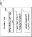
Fig. 9 is a diagram illustrating one example of the functional configuration of thecontrol unit 200. Thecontrol unit 200 includes amachining control unit 211, a holdingforce acquisition unit 212, and a holdingforce correction unit 213 as functional constituent elements. Themachining control unit 211, the holdingforce acquisition unit 212, and the holdingforce correction unit 213 are functional constituent elements provided by theCPU 201 of thecontrol unit 200, for example, executing various programs stored in theROM 202 orRAM 203. - The
machining control unit 211 controls themachine tool 1 during the machining of a workpiece W. Themachining control unit 211 causes thecollet chuck 41 to clamp the workpiece W, rotates thespindle 101, and controls the movement of thecutting tool 301 on thetool head 300, to cut the workpiece W, for example. Any known techniques can be used for controlling the machining of the workpiece W by thismachining control unit 211. - The holding
force acquisition unit 212 acquires the holding force applied to the workpiece W by thecollet chuck 41 in the closed state based on the period B - A as described above. The holding force is acquired on the basis of a correlation between the period B - A described above and the tightening amount of the nut. Namely, there is a linear relationship between the period B - A described above and the tightening amount of the nut (adjustment setting of the adjustment nut 51), and there is a linear relationship between the tightening amount of the nut and the holding force applied to the workpiece W by thecollet chuck 41 in the closed state. A holding force corresponding to a tightening amount of the nut can be acquired by calculation using the above-described linear relationship based on multiple actual measurements, which may be obtained experimentally, for example, by detecting discrete values in kilogram force (kgf) as a unit, for example, using a torque sensor on thecollet chuck 41. The holding force can be presented to the user as specific values, or as incremental levels of the holding force, with each level representing a preset range of nut tightening settings. -
Fig. 10 is a flowchart for creating holding force correlation data by the holding force acquisition unit. Preferably, the holding force correlation data is created during a preparation or setup process prior to machining of actual products. Namely, the workpiece W used in this process can be a spare workpiece W rather than the actual product. - First, the
control unit 200 issues a chuck close signal to theactuator 60, to cause thecollet chuck 41 to close and hold the workpiece W (S101). Then, the period A and the period B are acquired (S102 and S103). The period A is the period from when the control signal for the closing operation was issued to when the chuckopen position sensor 71 detects that thecollet chuck 41 is no longer in the open position. The period B is the period from when the control signal for the closing operation was issued to when the chuckclose position sensor 72 detects that thecollet chuck 41 has assumed the closed state. Thecontrol unit 200 stores the acquired periods A and B, and the period B - A obtained from these, in the storage means. - When there has been obtained enough data of periods A and B required for acquiring correlations between the period B - A and the amount of tightening of the nut (holding force) to determine the holding force (S104: YES), the correlation data of the period B - A and the holding force is created (S107). When there is not enough data of periods A and B (S104: NO), data acquisition is repeated. Namely, the
collet chuck 41 is opened (S105), the angle of theadjustment nut 51 is changed, to change the position of the chuck claws 47 (S106). The adjustment setting of theadjustment nut 51 may be changed manually by the user, or, when feasible, automatically by the machine. Steps S101 to S106 are repeated until necessary data is collected. -
Fig. 11 is a flowchart for detecting the holding force of the chuck using the holding force data obtained by the process ofFig. 10 . Holding force detection may be performed during the setting process prior to machining of actual products similarly to the process ofFig. 10 , or during the machining of actual products. - The
control unit 200 issues a chuck close signal to theactuator 60, to cause thecollet chuck 41 to close and hold the workpiece W (S201). Theadjustment nut 51 may be preset to an angle with a certain margin in this preparatory step as compared to the angle during the actual machining. Namely, the tightening amount of theadjustment nut 51 here is a provisional setting (first tightening amount) for obtaining an optimal setting (second tightening amount) for an optimal holding force of thecollet chuck 41. Then, the period A and the period B are acquired (S202 and S203). The period A is the period from when the control signal for the closing operation was issued to when the chuckopen position sensor 71 detects that thecollet chuck 41 is no longer in the open position. The period B is the period from when the control signal for the closing operation was issued to when the chuckclose position sensor 72 detects that thecollet chuck 41 has assumed the closed state. The period B - A obtained from the periods A and B is compared with the correlation between the period and the holding force (holding force data) acquired by the process ofFig. 10 , or calculated on the basis of this correlation, to determine a corresponding holding force (S204). The obtained holding force is informed to the user via theoutput unit 82 as a notification means (S205). - The user notified of the holding force by the steps described above can readjust the
adjustment nut 51 to achieve a desired holding force if necessary on the basis of the notified holding force. In the notification to the user at S205, the correlation between the nut adjustment setting and the holding force may also be displayed. Alternatively, in the case where a desired holding force has already been entered via theinput unit 81, a necessary adjustment amount of the nut (second tightening amount) for achieving the desired holding force may be determined at S204 and presented to the user at S205. - The holding
force correction unit 213 corrects the correlation between the obtained period B - A and the holding force (holding force data). As described above, the period A is basically when no load is applied (when load does not vary largely) during the chuck operation, and therefore the sensor detection time is substantially constant regardless of the tightening amount of theadjustment nut 51. However, after a long period of use, for example, the detection time can vary by the influence of changes in the air supply pressure of theair cylinder 61, and lubrication conditions between thechuck claws 47 and thebobbin 48. For example, if the air supply pressure of theair cylinder 61 has dropped from the standard 0.5 MPa to 0.4 MPa, the time A will be longer, which makes the period B longer, too. Therefore, it is preferable to correct the holding force data to account for such changes in machine behavior over time. Accordingly, in this embodiment, a delay (period C - D) in the sensor detection times when the chuck performs an opening operation caused by changes over time is obtained to determine a time lag (coefficient) to be used for the correction of the delay (period B - A) in the closing operation. -
Fig. 12 is a timing chart showing the response time of each of the chuckopen position sensor 71 and the chuckclose position sensor 72 in response to a chuck open signal issued by thecontrol unit 200 to theactuator 60. When theactuator 60 causes thecollet chuck 41 to perform the closing operation from the closed state to the open state, the period from when thecontrol unit 200 has issued a control signal to theactuator 60 to perform the opening operation to when the output of the chuckclose position sensor 72 switches from ON to OFF shall be referred to as period C (third time). The period from when thecontrol unit 200 has issued the control signal to theactuator 60 to perform the opening operation to when the output of the chuckopen position sensor 71 switches from OFF to ON shall be referred to as period D (fourth time). The transition period is period D - C (time difference). - This transition period D - C may fluctuate due to changes in machine behavior over time as described above. By comparing the period D - C when the machine is new with the period D - C after a certain time of operation (i.e., after wear or degradation has progressed), a coefficient (time lag) for correcting the holding force data can be obtained. Correcting the holding force data using this coefficient will enable determination of a more suitable holding force.
-
Fig. 13 is a flowchart for correcting the holding force correlation data by the holding force acquisition unit. This process is performed, after the creation of a standard set of holding force correlation data in the initial new state of the machine, every time the number of operations of the machine reaches a predetermined value, to update the holding force correlation data. - First, the
control unit 200 issues a chuck open signal to theactuator 60, to cause thecollet chuck 41 to open and release the workpiece W (S301). Then, the period C and the period D are acquired (S302 and S303). The period C is the period from when the control signal for the opening operation was issued to when the chuckclose position sensor 72 detects that thecollet chuck 41 is no longer in the closed position. The period D is the period from when the control signal for the opening operation was issued to when the chuckopen position sensor 71 detects that thecollet chuck 41 has assumed the open state. Thecontrol unit 200 stores the acquired periods C and D, and the period D - C obtained from these, in the storage means. - When there has been obtained enough data of periods C and D required for acquiring correlations between the period D - C and the tightening amount of the nut (holding force) to determine the holding force (S304: YES), the correlation data of the period D - C and the holding force is created (S307). When there is not enough data of periods C and D (S304: NO), data acquisition is repeated. Namely, the angle of the
adjustment nut 51 is changed to change the position of the chuck claws 47 (S305), after which thecollet chuck 41 is closed (S306), to hold the workpiece W again. The adjustment setting of theadjustment nut 51 may be changed manually by the user, or, when feasible, automatically by the machine. Steps S301 to S306 are repeated until necessary data is collected. - The latest holding force data (C', D') thus obtained by the process described above is compared with the initially obtained standard holding force data (C, D), to determine a time lag (coefficient) and to correct the holding force data corresponding to the period B - C (S308). For example, period B - A in the latest holding force data is corrected using a coefficient C'/C = α (α(B - A)). By using the corrected holding force data, a more appropriate holding force that reflects the changes over time of the machine can be set.
- As described above, according to this embodiment, the adjustment setting of the adjustment nut 51 (which corresponds to the holding force of the collet chuck 41) based on the time difference in sensor detection times enables an optimal holding force to be set, regardless of the reference point setting. Namely, the holding force of the chuck is correctly controlled, so that the machining precision can be improved.
- According to this embodiment, the holding force of the chuck, which is difficult to obtain (quantify) directly, can be better determined and even quantified using the intrinsic configurations of the machine tool, without requiring any additional configuration.
- It should be noted that specific configurations of the spindle unit, the chuck open/close mechanism including the collet chuck, the chuck sleeve, and the chuck claws, the actuators for driving various units, and the open/close sensors shown in the embodiment are only examples. Namely, other conventional or known configurations can be adopted as required.
-
- 1
- Machine tool
- 100
- Spindle unit
- 101
- Spindle
- 102
- Headstock
- 103
- Drive unit
- 2
- Base
- 200
- Control unit
- 300
- Tool head
- 301
- Cutting tool
- 41
- Collet chuck
- 43
- Chuck sleeve
- 44
- Compression coil spring
- 45
- Chuck opening/closing sleeve
- 46
- Balancing sleeve
- 47
- Chuck claw
- 48
- Bobbin
- 60
- Actuator
- W
- Workpiece
Claims (10)
- A machine tool comprising:a spindle including a chuck configured to hold a workpiece;an open/close mechanism configured to operate the chuck to assume either a closed state in which the chuck holds the workpiece or an open state in which the chuck allows the workpiece to be removed;sensors configured to detect whether or not the chuck is in the closed state, and whether or not the chuck is in the open state, respectively; anda control unit configured to control the open/close mechanism;wherein the machine tool includes an acquisition means configured to acquire a holding force applied to a workpiece by the chuck in the closed state based on a difference between a first time and a second time, the first time being, in a case where the open/close mechanism causes the chuck to perform a closing operation from the open state to the closed state, a time from when the control unit issues a control signal to the open/close mechanism to perform the closing operation to when the sensor detects that the chuck is no longer in the open state, and the second time being a time from when the control unit issues the control signal to the open/close period to when the sensor detects that the chuck has assumed the closed state.
- The machine tool according to claim 1, further comprising an adjustment mechanism configured to allow for adjustment of a tightening amount applied to the workpiece by the chuck in the closed state; and
a storage means configured to store a correlation between the difference, the tightening amount, and the holding force. - The machine tool according to claim 2, further comprising a correction means configured to correct the correlation based on a change with time in a second difference between a third time and a fourth time, the third time being, in a case where the open/close mechanism causes the chuck to perform an opening operation from the closed state to the open state, a time from when the control unit issues a control signal to the open/close mechanism to perform the opening operation to when the sensor detects that the chuck is no longer in the closed state, and the fourth time being a time from when the control unit issues the control signal to the open/close period to when the sensor detects that the chuck has assumed the open state.
- The machine tool according to claim 1, further comprising a notification means configured to notify information including the holding force to the outside.
- The machine tool according to claim 2, wherein the open/close mechanism comprises:a first actuating member provided to the spindle and configured to be able to assume a closed orientation in which the first actuating member actuates the chuck to assume the closed state and an open orientation in which the first actuating member actuates the chuck to assume the open state;a second actuating member provided to the spindle and configured to be displaceable relative to the first actuating member in a direction of a rotation axis of the spindle, the second actuating member being able to assume a closed position in which the second actuating member actuates the first actuating member to assume the closed orientation and an open position in which the second actuating member actuates the first actuating member to assume the open orientation; anda driving means including an air cylinder and configured to cause the second actuating member to move between the closed position and the open position.
- The machine tool according to claim 5, wherein the adjustment mechanism is configured to be able to change the tightening amount of the chuck by changing a position of the first actuating member relative to the spindle in the direction of the rotation axis.
- The machine tool according to claim 6, wherein the sensor is configured to detect whether or not the driving means is causing the second actuating member to be in the closed position, and whether or not the driving means is causing the second actuating member to be in the open position.
- A chuck holding force detection method for detecting a holding force applied to a workpiece by a chuck in a spindle of a machine tool in a case where the chuck holds the workpiece, comprising:a first step in which an open/close mechanism causes the chuck to perform a closing operation, from an open state in which the chuck allows a workpiece to be removed to a closed state in which the chuck holds a workpiece;a second step in which a first time and a second time are acquired, the first time being a time from when a control unit issues a control signal to the open/close mechanism for the closing operation in the first step to when a sensor detects that the chuck is no longer in the open state, and the second time being a time from when the control unit issues the control signal to the open/close mechanism to when the sensor detects that the chuck has assumed the closed state; anda third step in which the holding force is obtained on the basis of a correlation between a difference between the first time and the second time, a tightening amount adjusted by an adjustment mechanism applied to the workpiece by the chuck in the closed state, and the holding force.
- The chuck holding force detection method according to claim 8, further comprising:a fourth step in which the open/close mechanism causes the chuck to perform an opening operation, from the closed state to the open state;a fifth step in which a third time and a fourth time are acquired, the third time being a time from when the control unit issues a control signal to the open/close mechanism to perform the opening operation to when the sensor detects that the chuck is no longer in the closed state, and the fourth time being a time from when the control unit issues the control signal to the open/close period to when the sensor detects that the chuck has assumed the open state; anda sixth step in which the correlation is corrected on the basis of a change over time in a difference between the third time and the fourth time, the change being caused by repeating the fourth step and the fifth step.
- A method for setting a tightening amount applied to a workpiece by a chuck in a spindle of a machine tool in a case where the chuck holds the workpiece, comprising:a first step in which, with the chuck in a closed state in which the chuck holds a workpiece, and with a tightening amount applied to the workpiece by the chuck in the closed state being adjusted by an adjustment mechanism to a first tightening amount, an open/close mechanism causes the chuck to perform a closing operation, from an open state in which the chuck allows a workpiece to be removed to the closed state,a second step in which a first time and a second time are acquired, the first time being a time from when a control unit issues a control signal to the open/close mechanism for the closing operation in the first step to when a sensor detects that the chuck is no longer in the open state, and the second time being a time from when the control unit issues the control signal to the open/close mechanism to when the sensor detects that the chuck has assumed the closed state;a third step in which a second tightening amount that enables the holding force to be set to a desired value is obtained on the basis of a correlation between a difference between the first time and the second time, a tightening amount adjusted by the adjustment mechanism applied to the workpiece by the chuck in the closed state, and a holding force applied to the workpiece by the chuck in the closed state; anda fourth step in which the tightening amount is adjusted by the adjustment mechanism to the second tightening amount obtained in the third step.
Applications Claiming Priority (2)
| Application Number | Priority Date | Filing Date | Title |
|---|---|---|---|
| JP2022122732A JP2024019940A (en) | 2022-08-01 | 2022-08-01 | Machine tools, how to detect the gripping force of the chuck, and how to set the tightening amount of the chuck. |
| PCT/JP2023/026458 WO2024029338A1 (en) | 2022-08-01 | 2023-07-19 | Machine tool, chuck gripping force detection method, and chuck fastening amount setting method |
Publications (1)
| Publication Number | Publication Date |
|---|---|
| EP4566742A1 true EP4566742A1 (en) | 2025-06-11 |
Family
ID=89848860
Family Applications (1)
| Application Number | Title | Priority Date | Filing Date |
|---|---|---|---|
| EP23849893.5A Pending EP4566742A1 (en) | 2022-08-01 | 2023-07-19 | Machine tool, chuck gripping force detection method, and chuck fastening amount setting method |
Country Status (7)
| Country | Link |
|---|---|
| US (1) | US20260042154A1 (en) |
| EP (1) | EP4566742A1 (en) |
| JP (1) | JP2024019940A (en) |
| KR (1) | KR20250044296A (en) |
| CN (1) | CN119654209A (en) |
| TW (1) | TW202419178A (en) |
| WO (1) | WO2024029338A1 (en) |
Families Citing this family (1)
| Publication number | Priority date | Publication date | Assignee | Title |
|---|---|---|---|---|
| JP2026075743A (en) * | 2024-10-23 | 2026-05-11 | スター精密株式会社 | machine tools |
Family Cites Families (4)
| Publication number | Priority date | Publication date | Assignee | Title |
|---|---|---|---|---|
| JP2001096409A (en) | 1999-09-29 | 2001-04-10 | Hitachi Seiki Co Ltd | Method and apparatus for controlling electric chuck |
| JP2005324277A (en) * | 2004-05-13 | 2005-11-24 | Toyota Motor Corp | Clamp device and clamp confirmation method thereof |
| JP4638464B2 (en) * | 2007-03-29 | 2011-02-23 | 三菱重工業株式会社 | Machine tool spindle equipment |
| JP7275860B2 (en) * | 2019-05-27 | 2023-05-18 | オムロン株式会社 | Abnormality detection device |
-
2022
- 2022-08-01 JP JP2022122732A patent/JP2024019940A/en active Pending
-
2023
- 2023-07-19 EP EP23849893.5A patent/EP4566742A1/en active Pending
- 2023-07-19 CN CN202380056966.4A patent/CN119654209A/en active Pending
- 2023-07-19 WO PCT/JP2023/026458 patent/WO2024029338A1/en not_active Ceased
- 2023-07-19 KR KR1020257004625A patent/KR20250044296A/en active Pending
- 2023-07-19 US US19/100,375 patent/US20260042154A1/en active Pending
- 2023-07-24 TW TW112127569A patent/TW202419178A/en unknown
Also Published As
| Publication number | Publication date |
|---|---|
| CN119654209A (en) | 2025-03-18 |
| KR20250044296A (en) | 2025-03-31 |
| JP2024019940A (en) | 2024-02-14 |
| WO2024029338A1 (en) | 2024-02-08 |
| US20260042154A1 (en) | 2026-02-12 |
| TW202419178A (en) | 2024-05-16 |
Similar Documents
| Publication | Publication Date | Title |
|---|---|---|
| US9669472B2 (en) | Drilling apparatus and drilling method | |
| US9248508B2 (en) | Adjustable clamping device | |
| EP1080832B1 (en) | Tool holder and a runout correcting tool for a tool holder | |
| US20100188035A1 (en) | Machine tool and controlling method thereof | |
| KR101396689B1 (en) | machine tool | |
| US20260042154A1 (en) | Machine tool, chuck gripping force detection method, and chuck fastening amount setting method | |
| CN1073902A (en) | Be used to adjust the device at chuck center | |
| EP3819075B1 (en) | Machining tool | |
| JPH05200611A (en) | Chuck | |
| US8556551B2 (en) | Cutting tool having a shank-mounted adjustment ring | |
| JP2005199404A (en) | Rotation center, pressing force control device, lathe, turning method, and manufacturing method of turning product | |
| EP3640753A1 (en) | Machine tool provided with spindle having measurement function | |
| KR102427837B1 (en) | Automatic tube expanding device | |
| KR101993829B1 (en) | Method for adjusting chucking force to a workpiece in a lathe | |
| JPS62181803A (en) | Method and device for automatically adjusting cylindrical work guide means | |
| CN113770769A (en) | Thin-wall part machining tool | |
| JP2024019940A5 (en) | Machine tool, method for detecting gripping force of chuck, and method for setting tightening amount of chuck | |
| JP4471531B2 (en) | Material gripping device and automatic lathe | |
| JP4201553B2 (en) | Material guide device and automatic lathe | |
| JP2019084635A (en) | Chuck device | |
| KR101200910B1 (en) | Apparatus for detecting loop stiffness of spindle of machine tool | |
| JP7480003B2 (en) | Machine tool and method for controlling machine tool | |
| JP2026075743A (en) | machine tools | |
| JP3163325U (en) | Love chuck | |
| JP4437585B2 (en) | Guide bush inside diameter adjuster for spindle moving type automatic lathe |
Legal Events
| Date | Code | Title | Description |
|---|---|---|---|
| STAA | Information on the status of an ep patent application or granted ep patent |
Free format text: STATUS: THE INTERNATIONAL PUBLICATION HAS BEEN MADE |
|
| PUAI | Public reference made under article 153(3) epc to a published international application that has entered the european phase |
Free format text: ORIGINAL CODE: 0009012 |
|
| STAA | Information on the status of an ep patent application or granted ep patent |
Free format text: STATUS: REQUEST FOR EXAMINATION WAS MADE |
|
| 17P | Request for examination filed |
Effective date: 20250225 |
|
| AK | Designated contracting states |
Kind code of ref document: A1 Designated state(s): AL AT BE BG CH CY CZ DE DK EE ES FI FR GB GR HR HU IE IS IT LI LT LU LV MC ME MK MT NL NO PL PT RO RS SE SI SK SM TR |
|
| DAV | Request for validation of the european patent (deleted) | ||
| DAX | Request for extension of the european patent (deleted) |