EP4566502A1 - Pumping fluids in two ducts of a cleaning device - Google Patents
Pumping fluids in two ducts of a cleaning device Download PDFInfo
- Publication number
- EP4566502A1 EP4566502A1 EP23214632.4A EP23214632A EP4566502A1 EP 4566502 A1 EP4566502 A1 EP 4566502A1 EP 23214632 A EP23214632 A EP 23214632A EP 4566502 A1 EP4566502 A1 EP 4566502A1
- Authority
- EP
- European Patent Office
- Prior art keywords
- duct
- cleaning
- arrangement
- peristaltic pump
- cleaning device
- Prior art date
- Legal status (The legal status is an assumption and is not a legal conclusion. Google has not performed a legal analysis and makes no representation as to the accuracy of the status listed.)
- Withdrawn
Links
Images



Classifications
-
- A—HUMAN NECESSITIES
- A47—FURNITURE; DOMESTIC ARTICLES OR APPLIANCES; COFFEE MILLS; SPICE MILLS; SUCTION CLEANERS IN GENERAL
- A47L—DOMESTIC WASHING OR CLEANING; SUCTION CLEANERS IN GENERAL
- A47L11/00—Machines for cleaning floors, carpets, furniture, walls, or wall coverings
- A47L11/40—Parts or details of machines not provided for in groups A47L11/02 - A47L11/38, or not restricted to one of these groups, e.g. handles, arrangements of switches, skirts, buffers, levers
- A47L11/408—Means for supplying cleaning or surface treating agents
- A47L11/4088—Supply pumps; Spraying devices; Supply conduits
-
- F—MECHANICAL ENGINEERING; LIGHTING; HEATING; WEAPONS; BLASTING
- F04—POSITIVE - DISPLACEMENT MACHINES FOR LIQUIDS; PUMPS FOR LIQUIDS OR ELASTIC FLUIDS
- F04B—POSITIVE-DISPLACEMENT MACHINES FOR LIQUIDS; PUMPS
- F04B43/00—Machines, pumps, or pumping installations having flexible working members
- F04B43/12—Machines, pumps, or pumping installations having flexible working members having peristaltic action
Definitions
- the invention relates to a cleaning device configured to perform a cleaning action on a surface, comprising a surface interaction arrangement configured to be put to an operational position relative to the surface; and a cleaning arrangement configured to enable a cleaning action on the surface with the surface interaction arrangement in the operational position relative to the surface; wherein the cleaning arrangement is arranged and configured to perform two transport functions, namely, an outgoing transport function in transport of cleaning fluid from a source of the cleaning fluid to an outlet area of the surface interaction arrangement, and an incoming transport function in transport of fluid and particles from an inlet area of the surface interaction arrangement to a discharge site configured to receive the fluid and particles.
- cleaning a surface involves removing dirt from the surface.
- dirty as used in the present text is to be understood so as to cover any contamination as may be present on a surface and which is of such type and size that well-known cleaning actions such as vacuum cleaning and mopping are applicable to remove the contamination from the surface.
- Practical examples in this respect include dust and small particles of any kind, and also wet types of contamination such as spilled drinks.
- a practical example of the surface to be cleaned is a floor, wherein the floor may be of any kind, such as a wooden floor, a carpet floor, a tile floor, etc.
- Other practical examples of the surface to be cleaned are an indoor surface and a window.
- a cleaning device which is suitable to be used for cleaning a surface is a vacuum cleaner.
- a vacuum cleaner has a surface interaction arrangement, also known as cleaning nozzle or cleaning head, which is the part of the vacuum cleaner where the actual process of picking up dirt from a surface to be cleaned is to take place and which is therefore to be put on or at least close to the surface.
- a vacuum cleaner normally comprises a body portion including a dirt accumulating area as a discharge site configured to receive the dirt, and an arrangement configured to act on the surface interaction arrangement so that a suction force is prevailing in the surface interaction arrangement during operation of the vacuum cleaner.
- the suction force serves to facilitate transport of dirt that is picked up from the surface during operation of the vacuum cleaner towards the discharge side, wherein the dirt is made to pass an inlet area of the surface interaction arrangement.
- the suction force may also be an important factor in the actual process of picking up the dirt from the surface.
- the surface interaction arrangement may be equipped with at least one movable cleaning component for interacting with the surface in order to pick up the dirt, such as at least one rotatable brush which may serve as an agitator of the dirt and which may particularly be configured to help dislodge dirt from the surface and direct it towards the inlet area of the surface interaction arrangement so that the dirt can eventually be received at the discharge site.
- EP 4 209 159 A1 discloses a wet cleaning apparatus such as a wet mopping device, comprising a cleaner head and an underpressure generator arrangement.
- the wet cleaning apparatus comprises a dirty liquid collection tank for collecting liquid, with the underpressure generator arrangement being arranged such that the flow draws the liquid from at least one dirt inlet of the cleaner head to the dirty liquid collection tank.
- the cleaner head comprises at least one cleaning liquid outlet through which cleaning liquid is deliverable.
- the wet cleaning apparatus may comprise a cleaning liquid supply comprising a cleaning liquid reservoir for containing the cleaning liquid, the cleaning liquid reservoir being fluidly communicable or in fluid communication with the at least one cleaning liquid outlet.
- a cleaning liquid supply may, for example, comprise a cleaning liquid reservoir and a delivery arrangement, e.g. a delivery arrangement comprising a pump, for transporting the cleaning liquid to and through the at least one cleaning liquid outlet.
- the invention provides a cleaning device configured to perform a cleaning action on a surface, comprising:
- the cleaning arrangement of the cleaning device is configured to enable a cleaning action on the surface on the basis of a supply of cleaning fluid to the surface
- the cleaning arrangement comprises a first duct and a second duct, wherein both the first duct and the second duct are locally compressible, and wherein the first duct is arranged and configured to be involved in another one of two fluid transport functions of the cleaning arrangement than the second duct.
- the cleaning arrangement comprises a peristaltic pump comprising a single central unit which is rotatable about a central axis thereof and which is arranged and configured to act simultaneously on the first duct and the second duct.
- the invention involves use of no more than one pump in the cleaning arrangement for realizing both an outgoing transport function and an incoming transport function of the cleaning arrangement through the respective ducts.
- the peristaltic pump is designed to act simultaneously on the respective duct by means of a single central unit, this enables compactness of design of the cleaning arrangement and the cleaning device.
- the pump that is used is a peristaltic pump, it can be achieved that the respective ducts can be sealed in a fluid-tight fashion under all circumstances.
- the invention covers the possibility that, at least at the position of the peristaltic pump, a diameter of the first duct is different from a diameter of the second duct. This implies that the invention covers a possibility of allowing differences in the outgoing flow and the incoming flow, in spite of the fact that the flows are invoked by one and the same component in a shared pump.
- the peristaltic pump is operable in two different modes, namely, a first mode in which the first duct is used to transport cleaning fluid from the source of the cleaning fluid to the outlet area of the surface interaction arrangement and the second duct is used to transport fluid and particles from the inlet area of the surface interaction arrangement to the discharge site, and a second mode in which the first duct is used to transport fluid and particles from the inlet area of the surface interaction arrangement to the discharge site and the second duct is used to transport cleaning fluid from the source of the cleaning fluid to the outlet area of the surface interaction arrangement, wherein the cleaning device comprises a mechanism including valves which is controllable to allow coupling of the first duct to the source of the cleaning fluid and coupling of the second duct to the discharge site in the first mode, and to allow coupling of the first duct to the discharge site and coupling of the second duct to the source of the cleaning fluid in the second mode.
- the option of realizing two different modes of operation of the peristaltic pump may especially be interesting if the two ducts have a different diameter, because this enables a choice between a mode of operation involving a larger outgoing flow and a smaller incoming flow and a mode of operation involving a larger incoming flow and a smaller outgoing flow.
- a practical way of realizing the two different modes of operation of the peristaltic pump is obtained when the central unit of the peristaltic pump is rotatable both in a first direction of rotation about the central axis and in a second direction of rotation about the central axis opposite to the first direction of rotation about the central axis. The fact is that in that case, the two different modes of operation of the peristaltic pump are associated with the two different directions of rotation of the central unit and the two different settings of the mechanism including valves.
- the peristaltic pump comprises support surfaces configured to support the first duct and the second duct in the peristaltic pump.
- the ducts are enabled to remain in place in the peristaltic pump as they are locally pressed by the central unit, either in operation of the peristaltic pump or in an inactive condition of the peristaltic pump.
- the peristaltic pump comprises a housing which is generally shaped like a hollow cylinder having both a substantially circular exterior circumference and a substantially circular interior circumference, wherein the support surfaces are included in the housing.
- the first duct and the second duct are located at opposite sides of the central unit.
- the central unit of the peristaltic pump includes a set of outwardly projecting pressing elements for contacting and pressing the first duct and the second duct in an alternating sequence as the central unit rotates.
- the central unit is designed to pinch both the first duct and the second duct closed by means of at least two of the pressing elements in any position about the central axis.
- the cleaning device comprises a driving mechanism configured to drive the peristaltic pump in relation to movement of the surface interaction arrangement over the surface.
- a driving mechanism configured to drive the peristaltic pump in relation to movement of the surface interaction arrangement over the surface. This option is interesting if it is desired to have the functionality of providing cleaning fluid to the surface and the functionality of removing fluid and particles from the surface during the time that the surface interaction arrangement is moved over the surface.
- the driving mechanism may be designed to rely on the use of a sensor arrangement and the like, but it is also possible that the driving mechanism includes a mechanical coupling of the peristaltic pump, particularly the central unit of the peristaltic pump, to a wheel or another component of the surface interaction arrangement.
- peristaltic pump it is possible to drive the peristaltic pump in relation to movement of another component of the cleaning device, in which case a mechanical coupling between the peristaltic pump and that other component may be provided.
- another component is a rotating fan or the like of a vacuum mechanism in case the cleaning device is a vacuum cleaner.
- the cleaning device comprises a closure arrangement which is controllable to realize local closure of the first duct and the second duct at another position than the position of the peristaltic pump.
- the closure arrangement is further controllable to open at least one of the first duct and the second duct to air. This may be interesting if it is desirable to have a supply air to the fluid transported by means of the respective duct.
- the source of the cleaning fluid is located in the cleaning device and comprises a container. Further, it is possible that the cleaning arrangement comprises a container at the discharge site. Still further, it is possible that the cleaning arrangement comprises a separator arranged and configured to separate particles from fluid at a position between the inlet area of the surface interaction arrangement and the peristaltic pump. This allows for separate handling or further discharge of the fluid and the particles.
- the cleaning device can be of any suitable type, such as a wet cleaning device, in which case the cleaning fluid comprises a cleaning liquid such as water or a mixture of water and soap/detergent. Further, the invention covers embodiments of the cleaning device in which the cleaning device comprises at least one cleaning element arranged in the surface interaction arrangement and configured to interact with the surface, and/or a vacuum mechanism arranged and configured to realize vacuum at the position of the inlet area of the surface interaction arrangement, and/or a battery arranged and configured to provide electric power as necessary for operation of the cleaning device. Examples of the cleaning device include devices commonly referred to as wet mopping device, window cleaner, sweeper, wet vacuum cleaner, such as canister type, stick type or upright type.
- the cleaning device may be a robotic device designed to autonomously move the surface interaction arrangement over the surface, but it is also possible that the cleaning device comprises a handle to enable a person to take hold of the cleaning device and to move the cleaning device by hand.
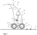
- Figure 1 illustrates the design of a wet vacuum cleaner 100 comprising a cleaning nozzle 101 which is functional as a surface interaction arrangement of the vacuum cleaner 100.
- the particular vacuum cleaner represented in figure 1 and described in the following is just one example of many types of cleaning devices which are feasible in the framework of the invention. In this respect, it is noted that the invention does not only relate to wet vacuum cleaners, but also to other types of vacuum cleaners, and to cleaning devices other than vacuum cleaners.
- the vacuum cleaner 100 is configured to be used for the purpose of subjecting a surface 10 such as a floor surface to a wet cleaning action.
- Figure 1 shows the vacuum cleaner 100 in a normal, operational orientation relative to the surface 10 to be cleaned.
- the use in the present text of a term having an orientation aspect is to be understood in relation to this normal, operational orientation of the vacuum cleaner 100 relative to the surface 10 to be cleaned, wherein it is assumed that the surface 10 is at a bottom position and the vacuum cleaner 100 is placed on the surface 10.
- the cleaning nozzle 101 is present in the vacuum cleaner 100 at a side of the vacuum cleaner 100 which is supposed to face the surface 10 during operation of the vacuum cleaner 100.
- the cleaning nozzle 101 accommodates two brushes 20 which are configured to interact with the surface 10 during operation of the vacuum cleaner 100.
- each of the brushes 20 is provided in the form of a roller which is rotatable about a rotation axis 21 which is defined by a central longitudinal axis of the roller, and each of the brushes 20 comprises a core element 22 and flexible microfiber elements 23 arranged on the core element 22, which does not alter the fact that other embodiments of the brushes 20 are possible as well, or that a cleaning device without any movable cleaning component is also in the scope of the invention.
- the brushes 20 are oriented such that their rotation axes 21 extend substantially parallel to the surface 10.
- the brushes 20 may be identical, but this is not necessary.
- the brushes 20 are arranged so as to be rotatable in opposite directions with respect to each other about their respective rotation axes 21.
- the cleaning nozzle 101 comprises a housing 30 which is configured to partially cover the brushes 20.
- the housing 30 can be made of a plastic material, for example.
- the vacuum cleaner 100 comprises a body portion 102 which is configured to be taken hold of by a person intending to use the vacuum cleaner 100.
- the cleaning nozzle 101 and the body portion 102 are removably couplable to each other.
- the body portion 102 can be shaped in any appropriate way.
- the outline of the body portion 102 as shown in figure 1 is of a diagrammatical nature only. It is practical if the body portion 102 comprises a handle so that the person can easily take hold of the body portion 102 and move the vacuum cleaner 100 over the surface 10 to be cleaned as desired.
- the vacuum cleaner 100 is equipped with a suitable electric drive mechanism (not shown).
- the vacuum cleaner 100 may be connectable to the mains and/or may be equipped with a suitable battery arrangement.
- the vacuum cleaner 100 is a cordless device comprising a rechargeable battery arrangement, in which case it may further be practical if the vacuum cleaner 100 is part of a set including a charging dock besides the vacuum cleaner 100. Such a set may also include a flushing tray that can be used for the purpose of cleaning the brushes 20.
- a simple dock which is without charging ability may be provided for receiving and holding the vacuum cleaner 100 while the vacuum cleaner 100 is not being operated.
- the vacuum cleaner 100 is equipped with a cleaning arrangement 40 comprising a liquid reservoir 41 which serves for containing a cleaning liquid such as water or a mixture of water and a cleaning agent, and further comprising a dirt reservoir 42 which serves for receiving and accumulating dirt 11 that is picked up from the surface 10 by the brushes 20 during operation of the vacuum cleaner 100.
- a cleaning arrangement 40 comprising a liquid reservoir 41 which serves for containing a cleaning liquid such as water or a mixture of water and a cleaning agent, and further comprising a dirt reservoir 42 which serves for receiving and accumulating dirt 11 that is picked up from the surface 10 by the brushes 20 during operation of the vacuum cleaner 100.
- both the liquid reservoir 41 and the dirt reservoir 42 are arranged in the body portion 102 of the vacuum cleaner 100.
- the cleaning arrangement 40 comprises a duct system including ducts 43, 44, and a peristaltic pump 50, as will be explained later in more detail with reference to figure 2 .
- a duct system including ducts 43, 44, and a peristaltic pump 50, as will be explained later in more detail with reference to figure 2 .
- both an outgoing flow of cleaning liquid from the liquid reservoir 41 to the surface 10 and an incoming flow of dirt 11 from the surface 10 to the dirt reservoir 42 are indicated by means of dashed arrows.
- the liquid reservoir 41 is removably coupled to the body portion 102 so that a person using the vacuum cleaner 100 is enabled to separate the liquid reservoir 41 from the body portion 102 when it is desired to take the liquid reservoir 41 to a place where the liquid reservoir 41 is to be filled with liquid.
- the dirt reservoir 42 is removably coupled to the body portion 102 so that a person using the vacuum cleaner 100 is enabled to separate the dirt reservoir 42 from the body portion 102 when it is desired to empty the dirt reservoir 42.
- the vacuum cleaner 100 includes a vacuum mechanism 60 configured to create underpressure that is functional to enable transport of dirt 11 from an area where the brushes 20 are located to one or more positions in the housing 30 where the duct system of the cleaning arrangement 40 can be accessed.
- a suction flow directed from the area where the brushes 20 are located towards the vacuum mechanism 60 is diagrammatically indicated by means of a series of block arrows in figure 1 .
- the brushes 20 are driven so as to rotate, and the pump 50 of the cleaning arrangement 40 and the vacuum mechanism 60 are activated.
- a practical example of the speed at which the brushes 20 are rotated is 4,800 rpm.
- cleaning liquid is retrieved from the liquid reservoir 41 and let out to the surface 10 to be cleaned. Any stains as may be present on an area of the surface 10 that is within reach of the brushes 20 are detached under the influence of the cleaning liquid and agitation by the brushes 20, and small particles and dust as may be present on the area of the surface 10 are removed along with liquid from that area.
- the dirt 11 is picked up from the surface 10 by tip portions of the microfiber elements 23 of the brushes 20 and is flung away from the tip portions as the brushes 20 rotate, at a position where the tip portions move out of contact to the surface 10.
- the dirt 11 Under the influence of the underpressure generated by the vacuum mechanism 60, the dirt 11 reaches the duct system of the cleaning arrangement 40 and is transported to the dirt reservoir 42 under the influence of the pump 50 of the cleaning arrangement 40.
- Proper use of the vacuum cleaner 100 involves movement of the vacuum cleaner 100 over the surface 10 to be cleaned, so that successive areas of the surface 10 can be subjected to the wet cleaning action described in the foregoing.
- the cleaning nozzle 101 may be provided with wheels, a roller or other means to facilitate the movement of the vacuum cleaner 100 over the surface 10.
- the vacuum cleaner 100 may be equipped with a user interface 70, which user interface 70 may include an on/off button 71, for example.
- the vacuum cleaner 100 may further comprise a controller 80 such as a microcontroller which is programmed to put the brushes 20 in motion and to activate both the cleaning arrangement 40 and the vacuum mechanism 60 in reaction to input received from a person using the vacuum cleaner 100 through the user interface 70 to that end.
- the controller 80 may be programmed and operable in any suitable way. For instance, it may be advantageous to provide a person using the vacuum cleaner 100 with a possibility to temporarily stop the supply of cleaning liquid to the surface 10 or to temporarily stop the removal of dirt 11 from the surface 10.
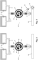
- Figure 2 illustrates a basic set-up of the cleaning arrangement 40.
- the cleaning arrangement 40 comprises a duct system including ducts 43, 44, and a peristaltic pump 50.
- a first duct 43 extends between an outlet area 31 of the cleaning nozzle 101 facing the area 24 where the brushes 20 are located and the liquid reservoir 41
- a second duct 44 extends between an inlet area 32 of the cleaning nozzle 101 facing the area 24 where the brushes 20 are located and the dirt reservoir 42.
- the first duct 43 serves to transport cleaning liquid from the liquid reservoir 41 to the area 24 where the brushes 20 are located
- the second duct 44 serves to transport dirt 11 in the form of liquid and particles from the area 24 where the brushes 20 are located to the dirt reservoir 42, as indicated in figure 2 by means of straight arrows.
- Both the first duct 43 and the second duct 44 extend through the peristaltic pump 50, and respective flows are generated in the ducts 43, 44 as the peristaltic pump 50 is operated.
- the peristaltic pump 50 comprises a housing 51 which is generally shaped like a hollow cylinder having both a substantially circular exterior circumference and a substantially circular interior circumference. Further, the peristaltic pump 50 comprises a central unit 52 which is rotatable about a central axis 53 thereof, as indicated in figure 2 by means of curved arrows.
- the first duct 43 and the second duct 44 are located in the housing 51 at opposite sides of the central unit 52, wherein each of the first duct 43 and the second duct 44 extends between the central unit 52 and a respective supporting surface 54, 55 which comprises a part of an interior surface 56 of the housing 51 and is concavely curved in a direction about the central unit 52.
- the central unit 52 includes three outwardly projecting pressing elements 57 for contacting and pressing the first duct 43 and the second duct 44.
- both the first duct 43 and the second duct 44 are locally compressible.
- the first duct 43 and the second duct 44 may comprise flexible material, at least at the position of the peristaltic pump 50 and possibly along their entire length.
- the dimensioning of the housing 51, the central unit 52 and the pressing elements 57 relative to the diameter of the respective ducts 43, 44 is chosen such that the ducts 43, 44 are locally pinched closed by the pressing elements 57.
- the pressing elements 52 are depicted with a circular circumference, but that does not alter the fact that other shapes of the pressing elements 52 are covered by the invention.
- Operation of the peristaltic pump 50 involves rotation of the central unit 52.
- liquid as present in the ducts 43, 44 at the position of the peristaltic pump 50 is pushed by the pressing elements 57, and new liquid is sucked into the peristaltic pump 50, whereby a flow of the liquid is obtained.
- the respective flows are in opposite directions. As mentioned, the flow in the first duct 43 is directed towards the area 24 where the brushes 20 are located, and the flow in the second duct 44 is directed towards the dirt reservoir 42.
- a notable aspect of the present peristaltic pump 50 is that the central unit 52 acts simultaneously on the first duct 43 and the second duct 44, i.e. that a single pump is used for generating two independent flows of fluid. There is no need for two separate pumps, or for a pump having two housings and two central units, for example, so that space is saved.
- the application of the present peristaltic pump 50 is appropriate in the context of a cleaning action not only involving a supply of cleaning fluid to a surface 10 but also a removal of cleaning fluid mixed with dirt from the surface 10.
- each of the ducts 43, 44 is always pressed by at least one of the pressing element 57, so that when the peristaltic pump 50 is stopped, the ducts 43, 44 are closed at the position of the peristaltic pump 50, and there is no need for additional closure means such as valves.
- the peristaltic pump 50 is activated as the vacuum cleaner 100 is operated. According to one feasible option, the peristaltic pump 50 is driven by means of electricity. However, according to another feasible option, which is especially interesting in case the vacuum cleaner 100 is a cordless device comprising a rechargeable battery arrangement, the peristaltic pump 50 is driven in a mechanical fashion.
- the invention covers an embodiment of the vacuum cleaner 100 in which the vacuum cleaner 100 comprises a driving mechanism 90 configured to drive the peristaltic pump 50 in relation to movement of the cleaning nozzle 101 over the surface 10.
- the driving mechanism 90 can be of any appropriate design and is only diagrammatically indicated in the figure by means of a dashed line.
- the driving mechanism 90 comprises a mechanical coupling between at least one wheel 25 of the cleaning nozzle 101 and the peristaltic pump 50, which coupling is capable of conveying rotary motion of the at least one wheel 25 to the peristaltic pump 50.
- electric energy can be saved, which is beneficial to the duration of the period in which the vacuum cleaner 100 can be used without needing to return the vacuum cleaner 100 to a position where the battery arrangement of the vacuum cleaner 100 can be charged.
- Figures 4 and 5 illustrate two different possibilities of applying a solenoid 45 in the cleaning arrangement 40.
- a solenoid 45 may be located at a position downstream of the liquid reservoir 41 and upstream of the peristaltic pump 50.
- a flow of cleaning liquid from the liquid reservoir 41 may be stopped even when the peristaltic pump 50 is in an active condition.
- a solenoid 45 may be located at a position downstream of the area 24 where the brushes 20 are located and upstream of the peristaltic pump 50.
- a process of removing liquid mixed with particles may be stopped even when the peristaltic pump 50 is in an active condition.
- the solenoid 45 is used to let in air to the flow of the fluid retrieved from the surface 10.
- the possibilities shown in figures 4 and 5 may be combined in one cleaning arrangement 40. If at least one solenoid 45 is present in the cleaning arrangement 40, indeed, the at least one solenoid 45 can be included in the control circuit of the cleaning device 100 including the user interface 70 and the controller 80.
- Figures 6 and 7 illustrate two different possibilities of separating particles from liquid in an incoming flow in the cleaning arrangement 40. Having the separation functionality in the cleaning arrangement 40 may be practical for various reasons, including a reason of preventing contamination and even clogging of the duct 43, 44 used for transport of the incoming flow and a reason of preventing jamming of the peristaltic pump 50.
- Figure 6 shows a first possibility which involves having a separator 46 directly downstream of the area 24 where the brushes 20 are located. Filtering means or other suitable means are used in the separator to retain the particles at the position of the separator 46 while allowing the liquid to move on in the direction of the peristaltic pump 50.
- Figure 7 shows a second possibility which involves having a separator 46 at the position of the dirt reservoir 42, in which case the dirt reservoir 42 is located at a position upstream of the peristaltic pump 50 rather than downstream of the peristaltic pump 50.
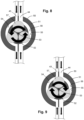
- Figures 8 and 9 illustrate a possibility of having different diameters of the ducts 43, 44.
- the diameter of the second duct 44 is twice the diameter of the first duct 43. This means that in the case that the first duct 43 is used for transport of the outgoing flow and the second duct 44 is used for transport of the incoming flow, more incoming fluid than outgoing fluid is displaced as the central unit 52 of the peristaltic pump 50 rotates, in a fixed ratio. It is also possible to use the first duct 43 for transport of the incoming flow and to use the second duct 44 for transport of the outgoing flow, namely by reversing the rotation of the central unit 52. In that case, more outgoing fluid than incoming fluid is displaced as the central unit 52 of the peristaltic pump 50 rotates, in the fixed ratio.
- a practical way of implementing an option of varying the relative extent to which cleaning liquid is supplied to the surface 10 and liquid and particles are removed from the surface 10 involves having a possibility to control which one of the ducts 43, 44 is connected to which one of the reservoirs 41, 42.
- figures 10 and 11 illustrate a possibility of having additional connections of the ducts 43, 44 and applying a valve system 47 in the cleaning arrangement 40.
- each of the ducts 43, 44 is connected to both reservoirs 41, 42 through a split end thereof, while one-way valves of the valve system 47 are used to open one of the ducts 43, 44 to one of the reservoirs 41, 42 and to close the one of the ducts 43, 44 to the other of the reservoirs 41, 42, while at the same time opening the other of the ducts 43, 44 to the other of the reservoirs 41, 42 and closing the other of the ducts 43, 44 to the one of the reservoirs 41, 42.
- Figure 10 relates to the situation in which the larger second duct 44 is used for the transport of the incoming flow.
- the respective one-way valves of the valve arrangement 47 act to enable the incoming flow to reach the dirt reservoir 42 through the second duct 44 while disabling the incoming flow to reach the liquid reservoir 41 through the second duct 44, and to enable an outgoing flow from the liquid reservoir 41 through the first duct 43 while disabling an outgoing flow from the dirt reservoir 42 through the first duct 43.
- Figure 11 relates to the situation in which the larger second duct 44 is used for the transport of the outgoing flow.
- the respective one-way valves of the valve arrangement 47 act to enable the outgoing flow from the liquid reservoir 41 through the second duct 44 while disabling an outgoing flow from the dirt reservoir 42 through the second duct 44, and to enable an incoming flow to reach the dirt reservoir 42 through the first duct 43 while disabling the incoming flow to reach the liquid reservoir 41 through the first duct 43.
- a cleaning device 100 which comprises a cleaning arrangement 40 designed to realize both an outgoing transport of cleaning fluid from a source 41 of the cleaning fluid towards a surface 10 to be cleaned and an incoming transport of fluid and particles from the surface 10 to a discharge site 42 configured to receive the fluid and particles.
- the cleaning arrangement 40 comprises a first duct 43 and a second duct 44, wherein both the first duct 43 and the second duct 44 are locally compressible, and wherein the first duct 43 is arranged and configured to be involved in another one of the outgoing transport of fluid and the incoming transport of fluid than the second duct 44.
- the cleaning arrangement 40 comprises a peristaltic pump 50 comprising a single central unit 52 which is rotatable about a central axis 53 thereof and which is arranged and configured to act simultaneously on the first duct 43 and the second duct 44.
- the first duct 43 and the second duct 44 may be located at opposite sides of the central unit 52 of the peristaltic pump 50, in a housing 51 of the peristaltic pump 50.
- the fact that separate fluid flows are induced by one and the same peristaltic pump 50 does not necessarily mean that the fluid flows need to have the same characteristics apart from being in opposite directions.
- a diameter of the first duct 43 can be chosen so as to be different from a diameter of the second duct 44, so that a flow rate and a pressure of the flow in the first duct 43 are different from the flow rate and the pressure of the flow in the second duct 44.
Landscapes
- Engineering & Computer Science (AREA)
- Mechanical Engineering (AREA)
- General Engineering & Computer Science (AREA)
- Cleaning In General (AREA)
Abstract
In the context of cleaning surfaces by using cleaning fluid, a cleaning device is provided which comprises a cleaning arrangement (40) designed to realize both an outgoing transport of cleaning fluid from a source (41) of the cleaning fluid towards a surface to be cleaned and an incoming transport of fluid and particles from the surface to a discharge site (42) configured to receive the fluid and particles. To this end, the cleaning arrangement (40) comprises a first duct (43) and a second duct (44) which are both locally compressible, and a peristaltic pump (50) comprising a single central unit (52) which is rotatable about a central axis (53) thereof and which is arranged and configured to act simultaneously on the first duct (43) and the second duct (44). The respective ducts (43, 44) may be located at opposite sides of the central unit (52) of the peristaltic pump (50).
Description
- The invention relates to a cleaning device configured to perform a cleaning action on a surface, comprising a surface interaction arrangement configured to be put to an operational position relative to the surface; and a cleaning arrangement configured to enable a cleaning action on the surface with the surface interaction arrangement in the operational position relative to the surface; wherein the cleaning arrangement is arranged and configured to perform two transport functions, namely, an outgoing transport function in transport of cleaning fluid from a source of the cleaning fluid to an outlet area of the surface interaction arrangement, and an incoming transport function in transport of fluid and particles from an inlet area of the surface interaction arrangement to a discharge site configured to receive the fluid and particles.
- Generally speaking, cleaning a surface involves removing dirt from the surface. The term "dirt" as used in the present text is to be understood so as to cover any contamination as may be present on a surface and which is of such type and size that well-known cleaning actions such as vacuum cleaning and mopping are applicable to remove the contamination from the surface. Practical examples in this respect include dust and small particles of any kind, and also wet types of contamination such as spilled drinks. A practical example of the surface to be cleaned is a floor, wherein the floor may be of any kind, such as a wooden floor, a carpet floor, a tile floor, etc. Other practical examples of the surface to be cleaned are an indoor surface and a window.
- A well-known example of a cleaning device which is suitable to be used for cleaning a surface is a vacuum cleaner. Generally, a vacuum cleaner has a surface interaction arrangement, also known as cleaning nozzle or cleaning head, which is the part of the vacuum cleaner where the actual process of picking up dirt from a surface to be cleaned is to take place and which is therefore to be put on or at least close to the surface. Further, a vacuum cleaner normally comprises a body portion including a dirt accumulating area as a discharge site configured to receive the dirt, and an arrangement configured to act on the surface interaction arrangement so that a suction force is prevailing in the surface interaction arrangement during operation of the vacuum cleaner. The suction force serves to facilitate transport of dirt that is picked up from the surface during operation of the vacuum cleaner towards the discharge side, wherein the dirt is made to pass an inlet area of the surface interaction arrangement. The suction force may also be an important factor in the actual process of picking up the dirt from the surface. On the other hand, the surface interaction arrangement may be equipped with at least one movable cleaning component for interacting with the surface in order to pick up the dirt, such as at least one rotatable brush which may serve as an agitator of the dirt and which may particularly be configured to help dislodge dirt from the surface and direct it towards the inlet area of the surface interaction arrangement so that the dirt can eventually be received at the discharge site.
-
EP 4 209 159 A1 discloses a wet cleaning apparatus such as a wet mopping device, comprising a cleaner head and an underpressure generator arrangement. In some embodiments, the wet cleaning apparatus comprises a dirty liquid collection tank for collecting liquid, with the underpressure generator arrangement being arranged such that the flow draws the liquid from at least one dirt inlet of the cleaner head to the dirty liquid collection tank. Further, in some embodiments, the cleaner head comprises at least one cleaning liquid outlet through which cleaning liquid is deliverable. The wet cleaning apparatus may comprise a cleaning liquid supply comprising a cleaning liquid reservoir for containing the cleaning liquid, the cleaning liquid reservoir being fluidly communicable or in fluid communication with the at least one cleaning liquid outlet. Such a cleaning liquid supply may, for example, comprise a cleaning liquid reservoir and a delivery arrangement, e.g. a delivery arrangement comprising a pump, for transporting the cleaning liquid to and through the at least one cleaning liquid outlet. - It is an object of the invention to provide a lightweight and compact design of a cleaning device comprising a surface interaction arrangement and a cleaning arrangement, without compromising capabilities of the cleaning arrangement, particularly a capability of the cleaning arrangement to enable an outgoing flow of cleaning fluid and an incoming flow of fluid and particles in the cleaning device. It is a further object of the invention to realize reliable functioning of the cleaning arrangement while allowing differences between the outgoing flow and the incoming flow, such as different displaced flow volumes per time unit.
- In view of the foregoing, the invention provides a cleaning device configured to perform a cleaning action on a surface, comprising:
- a surface interaction arrangement configured to be put to an operational position relative to the surface; and
- a cleaning arrangement configured to enable a cleaning action on the surface with the surface interaction arrangement in the operational position relative to the surface;
- the cleaning arrangement is arranged and configured to perform two transport functions, namely, an outgoing transport function in transport of cleaning fluid from a source of the cleaning fluid to an outlet area of the surface interaction arrangement, and an incoming transport function in transport of fluid and particles from an inlet area of the surface interaction arrangement to a discharge site configured to receive the fluid and particles;
- the cleaning arrangement comprises a first duct and a second duct, wherein both the first duct and the second duct are locally compressible, and wherein the first duct is arranged and configured to be involved in another one of the two transport functions of the cleaning arrangement than the second duct; and
- the cleaning arrangement further comprises a peristaltic pump comprising a single central unit which is rotatable about a central axis thereof and which is arranged and configured to act simultaneously on the first duct and the second duct.
- It follows from the above definition of the cleaning device of the invention that the cleaning arrangement of the cleaning device is configured to enable a cleaning action on the surface on the basis of a supply of cleaning fluid to the surface, and that the cleaning arrangement comprises a first duct and a second duct, wherein both the first duct and the second duct are locally compressible, and wherein the first duct is arranged and configured to be involved in another one of two fluid transport functions of the cleaning arrangement than the second duct. Further, the cleaning arrangement comprises a peristaltic pump comprising a single central unit which is rotatable about a central axis thereof and which is arranged and configured to act simultaneously on the first duct and the second duct. Hence, the invention involves use of no more than one pump in the cleaning arrangement for realizing both an outgoing transport function and an incoming transport function of the cleaning arrangement through the respective ducts. Especially since the peristaltic pump is designed to act simultaneously on the respective duct by means of a single central unit, this enables compactness of design of the cleaning arrangement and the cleaning device. Further, as the pump that is used is a peristaltic pump, it can be achieved that the respective ducts can be sealed in a fluid-tight fashion under all circumstances.
- The invention covers the possibility that, at least at the position of the peristaltic pump, a diameter of the first duct is different from a diameter of the second duct. This implies that the invention covers a possibility of allowing differences in the outgoing flow and the incoming flow, in spite of the fact that the flows are invoked by one and the same component in a shared pump.
- Advantageously, the peristaltic pump is operable in two different modes, namely, a first mode in which the first duct is used to transport cleaning fluid from the source of the cleaning fluid to the outlet area of the surface interaction arrangement and the second duct is used to transport fluid and particles from the inlet area of the surface interaction arrangement to the discharge site, and a second mode in which the first duct is used to transport fluid and particles from the inlet area of the surface interaction arrangement to the discharge site and the second duct is used to transport cleaning fluid from the source of the cleaning fluid to the outlet area of the surface interaction arrangement, wherein the cleaning device comprises a mechanism including valves which is controllable to allow coupling of the first duct to the source of the cleaning fluid and coupling of the second duct to the discharge site in the first mode, and to allow coupling of the first duct to the discharge site and coupling of the second duct to the source of the cleaning fluid in the second mode. The option of realizing two different modes of operation of the peristaltic pump may especially be interesting if the two ducts have a different diameter, because this enables a choice between a mode of operation involving a larger outgoing flow and a smaller incoming flow and a mode of operation involving a larger incoming flow and a smaller outgoing flow. A practical way of realizing the two different modes of operation of the peristaltic pump is obtained when the central unit of the peristaltic pump is rotatable both in a first direction of rotation about the central axis and in a second direction of rotation about the central axis opposite to the first direction of rotation about the central axis. The fact is that in that case, the two different modes of operation of the peristaltic pump are associated with the two different directions of rotation of the central unit and the two different settings of the mechanism including valves.
- It is practical if the peristaltic pump comprises support surfaces configured to support the first duct and the second duct in the peristaltic pump. On the basis of contact to the support surfaces, the ducts are enabled to remain in place in the peristaltic pump as they are locally pressed by the central unit, either in operation of the peristaltic pump or in an inactive condition of the peristaltic pump. For example, the peristaltic pump comprises a housing which is generally shaped like a hollow cylinder having both a substantially circular exterior circumference and a substantially circular interior circumference, wherein the support surfaces are included in the housing. In any case, it may be practical if the first duct and the second duct are located at opposite sides of the central unit.
- As is known per se in the field of peristaltic pumps, it is possible that the central unit of the peristaltic pump includes a set of outwardly projecting pressing elements for contacting and pressing the first duct and the second duct in an alternating sequence as the central unit rotates. In this respect, it may be so that the central unit is designed to pinch both the first duct and the second duct closed by means of at least two of the pressing elements in any position about the central axis. Such a design of the central unit guarantees effective pumping during operation of the peristaltic pump as well as fluid-tight sealing of the ducts when the peristaltic pump is in the inactive condition.
- An embodiment of the cleaning device is feasible in which the cleaning device comprises a driving mechanism configured to drive the peristaltic pump in relation to movement of the surface interaction arrangement over the surface. This option is interesting if it is desired to have the functionality of providing cleaning fluid to the surface and the functionality of removing fluid and particles from the surface during the time that the surface interaction arrangement is moved over the surface. The driving mechanism may be designed to rely on the use of a sensor arrangement and the like, but it is also possible that the driving mechanism includes a mechanical coupling of the peristaltic pump, particularly the central unit of the peristaltic pump, to a wheel or another component of the surface interaction arrangement. Alternatively, it is possible to drive the peristaltic pump in relation to movement of another component of the cleaning device, in which case a mechanical coupling between the peristaltic pump and that other component may be provided. An example of another component is a rotating fan or the like of a vacuum mechanism in case the cleaning device is a vacuum cleaner.
- Further possibilities of operating the cleaning device are obtained if the cleaning device comprises a closure arrangement which is controllable to realize local closure of the first duct and the second duct at another position than the position of the peristaltic pump. By choosing an appropriate setting of the closure arrangement, it is possible to operate the cleaning device so as to realize both transport of an outgoing flow and transport of an incoming flow, transport of only an outgoing flow, or transport of only an incoming flow. Optionally the closure arrangement is further controllable to open at least one of the first duct and the second duct to air. This may be interesting if it is desirable to have a supply air to the fluid transported by means of the respective duct.
- In respect of the source of the cleaning fluid, it is noted that it is possible that the source of the cleaning fluid is located in the cleaning device and comprises a container. Further, it is possible that the cleaning arrangement comprises a container at the discharge site. Still further, it is possible that the cleaning arrangement comprises a separator arranged and configured to separate particles from fluid at a position between the inlet area of the surface interaction arrangement and the peristaltic pump. This allows for separate handling or further discharge of the fluid and the particles.
- The cleaning device can be of any suitable type, such as a wet cleaning device, in which case the cleaning fluid comprises a cleaning liquid such as water or a mixture of water and soap/detergent. Further, the invention covers embodiments of the cleaning device in which the cleaning device comprises at least one cleaning element arranged in the surface interaction arrangement and configured to interact with the surface, and/or a vacuum mechanism arranged and configured to realize vacuum at the position of the inlet area of the surface interaction arrangement, and/or a battery arranged and configured to provide electric power as necessary for operation of the cleaning device. Examples of the cleaning device include devices commonly referred to as wet mopping device, window cleaner, sweeper, wet vacuum cleaner, such as canister type, stick type or upright type. The cleaning device may be a robotic device designed to autonomously move the surface interaction arrangement over the surface, but it is also possible that the cleaning device comprises a handle to enable a person to take hold of the cleaning device and to move the cleaning device by hand.
- The above-described and other aspects of the invention will be apparent from and elucidated with reference to the following detailed description of a practical embodiment of a wet vacuum cleaner comprising a cleaning nozzle and a cleaning arrangement, with an emphasis on options in respect of the set-up of the cleaning arrangement.
- The invention will now be explained in greater detail with reference to the figures, in which equal or similar parts are indicated by the same reference signs, and in which:
-
Figure 1 diagrammatically shows a portion of a floor having a surface to be cleaned and components of a wet vacuum cleaner comprising a cleaning nozzle and a cleaning arrangement; -
Figure 2 illustrates a basic set-up of the cleaning arrangement, in which the cleaning arrangement comprises a first duct, a second duct, and a peristaltic pump acting on both the first duct and the second duct; -
Figure 3 illustrates a possibility of driving the peristaltic pump; -
Figures 4 and 5 illustrate two different possibilities of applying a solenoid in the cleaning arrangement; -
Figures 6 and 7 illustrate two different possibilities of separating particles from liquid in an incoming flow in the cleaning arrangement; -
Figures 8 and 9 illustrate a possibility of having different diameters of the ducts, whereinfigure 8 illustrates a first mode of operation of the peristaltic pump, and whereinfigure 9 illustrates another mode of operation of the peristaltic pump; and -
Figures 10 and 11 illustrate a possibility of having additional connections of the ducts and applying a valve system in the cleaning arrangement, whereinfigure 10 illustrates a first mode of operation of the peristaltic pump, and whereinfigure 11 illustrates another mode of operation of the peristaltic pump. -
Figure 1 illustrates the design of awet vacuum cleaner 100 comprising acleaning nozzle 101 which is functional as a surface interaction arrangement of thevacuum cleaner 100. The particular vacuum cleaner represented infigure 1 and described in the following is just one example of many types of cleaning devices which are feasible in the framework of the invention. In this respect, it is noted that the invention does not only relate to wet vacuum cleaners, but also to other types of vacuum cleaners, and to cleaning devices other than vacuum cleaners. - The
vacuum cleaner 100 is configured to be used for the purpose of subjecting asurface 10 such as a floor surface to a wet cleaning action.Figure 1 shows thevacuum cleaner 100 in a normal, operational orientation relative to thesurface 10 to be cleaned. The use in the present text of a term having an orientation aspect is to be understood in relation to this normal, operational orientation of thevacuum cleaner 100 relative to thesurface 10 to be cleaned, wherein it is assumed that thesurface 10 is at a bottom position and thevacuum cleaner 100 is placed on thesurface 10. - The cleaning
nozzle 101 is present in thevacuum cleaner 100 at a side of thevacuum cleaner 100 which is supposed to face thesurface 10 during operation of thevacuum cleaner 100. The cleaningnozzle 101 accommodates twobrushes 20 which are configured to interact with thesurface 10 during operation of thevacuum cleaner 100. For example, each of thebrushes 20 is provided in the form of a roller which is rotatable about arotation axis 21 which is defined by a central longitudinal axis of the roller, and each of thebrushes 20 comprises acore element 22 andflexible microfiber elements 23 arranged on thecore element 22, which does not alter the fact that other embodiments of thebrushes 20 are possible as well, or that a cleaning device without any movable cleaning component is also in the scope of the invention. In the present example, thebrushes 20 are oriented such that theirrotation axes 21 extend substantially parallel to thesurface 10. Thebrushes 20 may be identical, but this is not necessary. As indicated infigure 1 by means of curved arrows depicted at the position of thebrushes 20, thebrushes 20 are arranged so as to be rotatable in opposite directions with respect to each other about their respective rotation axes 21. The cleaningnozzle 101 comprises ahousing 30 which is configured to partially cover thebrushes 20. Thehousing 30 can be made of a plastic material, for example. - Besides the cleaning
nozzle 101, thevacuum cleaner 100 comprises abody portion 102 which is configured to be taken hold of by a person intending to use thevacuum cleaner 100. Preferably, the cleaningnozzle 101 and thebody portion 102 are removably couplable to each other. Thebody portion 102 can be shaped in any appropriate way. The outline of thebody portion 102 as shown infigure 1 is of a diagrammatical nature only. It is practical if thebody portion 102 comprises a handle so that the person can easily take hold of thebody portion 102 and move thevacuum cleaner 100 over thesurface 10 to be cleaned as desired. - For the purpose of driving the
brushes 20 during operation of thevacuum cleaner 100, thevacuum cleaner 100 is equipped with a suitable electric drive mechanism (not shown). For the purpose of powering at least the drive mechanism, thevacuum cleaner 100 may be connectable to the mains and/or may be equipped with a suitable battery arrangement. Preferably, thevacuum cleaner 100 is a cordless device comprising a rechargeable battery arrangement, in which case it may further be practical if thevacuum cleaner 100 is part of a set including a charging dock besides thevacuum cleaner 100. Such a set may also include a flushing tray that can be used for the purpose of cleaning thebrushes 20. In case thevacuum cleaner 100 is not equipped with a battery, a simple dock which is without charging ability may be provided for receiving and holding thevacuum cleaner 100 while thevacuum cleaner 100 is not being operated. - The
vacuum cleaner 100 is equipped with acleaning arrangement 40 comprising aliquid reservoir 41 which serves for containing a cleaning liquid such as water or a mixture of water and a cleaning agent, and further comprising adirt reservoir 42 which serves for receiving and accumulatingdirt 11 that is picked up from thesurface 10 by thebrushes 20 during operation of thevacuum cleaner 100. In the present example, both theliquid reservoir 41 and thedirt reservoir 42 are arranged in thebody portion 102 of thevacuum cleaner 100. For the purpose of performing two transport functions, namely, an outgoing transport function in transport of cleaning liquid from theliquid reservoir 41 to an outlet area of thecleaning nozzle 101, and an incoming transport function in transport ofdirt 11 from an inlet area of thecleaning nozzle 101 to thedirt reservoir 42, the cleaningarrangement 40 comprises a ductsystem including ducts peristaltic pump 50, as will be explained later in more detail with reference tofigure 2 . Infigure 1 , both an outgoing flow of cleaning liquid from theliquid reservoir 41 to thesurface 10 and an incoming flow ofdirt 11 from thesurface 10 to thedirt reservoir 42 are indicated by means of dashed arrows. - It is practical if the
liquid reservoir 41 is removably coupled to thebody portion 102 so that a person using thevacuum cleaner 100 is enabled to separate theliquid reservoir 41 from thebody portion 102 when it is desired to take theliquid reservoir 41 to a place where theliquid reservoir 41 is to be filled with liquid. Likewise, it is practical if thedirt reservoir 42 is removably coupled to thebody portion 102 so that a person using thevacuum cleaner 100 is enabled to separate thedirt reservoir 42 from thebody portion 102 when it is desired to empty thedirt reservoir 42. - The
vacuum cleaner 100 includes avacuum mechanism 60 configured to create underpressure that is functional to enable transport ofdirt 11 from an area where thebrushes 20 are located to one or more positions in thehousing 30 where the duct system of thecleaning arrangement 40 can be accessed. A suction flow directed from the area where thebrushes 20 are located towards thevacuum mechanism 60 is diagrammatically indicated by means of a series of block arrows infigure 1 . - Basic aspects of the way in which the
vacuum cleaner 100 is operated are as follows. During operation, thebrushes 20 are driven so as to rotate, and thepump 50 of thecleaning arrangement 40 and thevacuum mechanism 60 are activated. A practical example of the speed at which thebrushes 20 are rotated is 4,800 rpm. Under the influence of thepump 50 of thecleaning arrangement 40, cleaning liquid is retrieved from theliquid reservoir 41 and let out to thesurface 10 to be cleaned. Any stains as may be present on an area of thesurface 10 that is within reach of thebrushes 20 are detached under the influence of the cleaning liquid and agitation by thebrushes 20, and small particles and dust as may be present on the area of thesurface 10 are removed along with liquid from that area. In particular, thedirt 11 is picked up from thesurface 10 by tip portions of themicrofiber elements 23 of thebrushes 20 and is flung away from the tip portions as thebrushes 20 rotate, at a position where the tip portions move out of contact to thesurface 10. Under the influence of the underpressure generated by thevacuum mechanism 60, thedirt 11 reaches the duct system of thecleaning arrangement 40 and is transported to thedirt reservoir 42 under the influence of thepump 50 of thecleaning arrangement 40. Proper use of thevacuum cleaner 100 involves movement of thevacuum cleaner 100 over thesurface 10 to be cleaned, so that successive areas of thesurface 10 can be subjected to the wet cleaning action described in the foregoing. The cleaningnozzle 101 may be provided with wheels, a roller or other means to facilitate the movement of thevacuum cleaner 100 over thesurface 10. - As illustrated in
figure 1 , thevacuum cleaner 100 may be equipped with auser interface 70, whichuser interface 70 may include an on/offbutton 71, for example. Thevacuum cleaner 100 may further comprise acontroller 80 such as a microcontroller which is programmed to put thebrushes 20 in motion and to activate both thecleaning arrangement 40 and thevacuum mechanism 60 in reaction to input received from a person using thevacuum cleaner 100 through theuser interface 70 to that end. Generally speaking, thecontroller 80 may be programmed and operable in any suitable way. For instance, it may be advantageous to provide a person using thevacuum cleaner 100 with a possibility to temporarily stop the supply of cleaning liquid to thesurface 10 or to temporarily stop the removal ofdirt 11 from thesurface 10. -
Figure 2 illustrates a basic set-up of thecleaning arrangement 40. As suggested earlier, aside from theliquid reservoir 41 and thedirt reservoir 42, the cleaningarrangement 40 comprises a ductsystem including ducts peristaltic pump 50. In the present example, afirst duct 43 extends between anoutlet area 31 of thecleaning nozzle 101 facing thearea 24 where thebrushes 20 are located and theliquid reservoir 41, and asecond duct 44 extends between aninlet area 32 of thecleaning nozzle 101 facing thearea 24 where thebrushes 20 are located and thedirt reservoir 42. Hence, in the present example, thefirst duct 43 serves to transport cleaning liquid from theliquid reservoir 41 to thearea 24 where thebrushes 20 are located, and thesecond duct 44 serves to transportdirt 11 in the form of liquid and particles from thearea 24 where thebrushes 20 are located to thedirt reservoir 42, as indicated infigure 2 by means of straight arrows. Both thefirst duct 43 and thesecond duct 44 extend through theperistaltic pump 50, and respective flows are generated in theducts peristaltic pump 50 is operated. - The
peristaltic pump 50 comprises ahousing 51 which is generally shaped like a hollow cylinder having both a substantially circular exterior circumference and a substantially circular interior circumference. Further, theperistaltic pump 50 comprises acentral unit 52 which is rotatable about acentral axis 53 thereof, as indicated infigure 2 by means of curved arrows. Thefirst duct 43 and thesecond duct 44 are located in thehousing 51 at opposite sides of thecentral unit 52, wherein each of thefirst duct 43 and thesecond duct 44 extends between thecentral unit 52 and a respective supportingsurface interior surface 56 of thehousing 51 and is concavely curved in a direction about thecentral unit 52. Thecentral unit 52 includes three outwardly projectingpressing elements 57 for contacting and pressing thefirst duct 43 and thesecond duct 44. In this respect, it is noted that both thefirst duct 43 and thesecond duct 44 are locally compressible. For example, thefirst duct 43 and thesecond duct 44 may comprise flexible material, at least at the position of theperistaltic pump 50 and possibly along their entire length. Advantageously, the dimensioning of thehousing 51, thecentral unit 52 and thepressing elements 57 relative to the diameter of therespective ducts ducts pressing elements 57. In the respective figures, thepressing elements 52 are depicted with a circular circumference, but that does not alter the fact that other shapes of thepressing elements 52 are covered by the invention. - Operation of the
peristaltic pump 50 involves rotation of thecentral unit 52. In the process, as a result of the interaction of the movingpressing elements 57 with theducts central unit 52, liquid as present in theducts peristaltic pump 50 is pushed by thepressing elements 57, and new liquid is sucked into theperistaltic pump 50, whereby a flow of the liquid is obtained. In the shown example, the respective flows are in opposite directions. As mentioned, the flow in thefirst duct 43 is directed towards thearea 24 where thebrushes 20 are located, and the flow in thesecond duct 44 is directed towards thedirt reservoir 42. A notable aspect of the presentperistaltic pump 50 is that thecentral unit 52 acts simultaneously on thefirst duct 43 and thesecond duct 44, i.e. that a single pump is used for generating two independent flows of fluid. There is no need for two separate pumps, or for a pump having two housings and two central units, for example, so that space is saved. The application of the presentperistaltic pump 50 is appropriate in the context of a cleaning action not only involving a supply of cleaning fluid to asurface 10 but also a removal of cleaning fluid mixed with dirt from thesurface 10. Further, in the presentperistaltic pump 50, with the threepressing elements 57 distributed equally about thecentral axis 53 of thecentral unit 52, it is achieved that each of theducts pressing element 57, so that when theperistaltic pump 50 is stopped, theducts peristaltic pump 50, and there is no need for additional closure means such as valves. - As mentioned earlier, the
peristaltic pump 50 is activated as thevacuum cleaner 100 is operated. According to one feasible option, theperistaltic pump 50 is driven by means of electricity. However, according to another feasible option, which is especially interesting in case thevacuum cleaner 100 is a cordless device comprising a rechargeable battery arrangement, theperistaltic pump 50 is driven in a mechanical fashion. In this respect, with reference tofigure 3 , it is noted that the invention covers an embodiment of thevacuum cleaner 100 in which thevacuum cleaner 100 comprises adriving mechanism 90 configured to drive theperistaltic pump 50 in relation to movement of thecleaning nozzle 101 over thesurface 10. Thedriving mechanism 90 can be of any appropriate design and is only diagrammatically indicated in the figure by means of a dashed line. For example, as illustrated, thedriving mechanism 90 comprises a mechanical coupling between at least onewheel 25 of thecleaning nozzle 101 and theperistaltic pump 50, which coupling is capable of conveying rotary motion of the at least onewheel 25 to theperistaltic pump 50. In this way, electric energy can be saved, which is beneficial to the duration of the period in which thevacuum cleaner 100 can be used without needing to return thevacuum cleaner 100 to a position where the battery arrangement of thevacuum cleaner 100 can be charged. It is an insight of the invention that it is actually possible to save electric energy in this way without hampering the cleaning functionality of thevacuum cleaner 100, because thecleaning nozzle 101 is normally continuously moved over thesurface 10 by a person using thevacuum cleaner 100, and it is normally not necessary, even undesirable, to have an ongoing supply of cleaning fluid to thesurface 10 in case the cleaningnozzle 101 is kept stationary on thesurface 10 for some reason. -
Figures 4 and 5 illustrate two different possibilities of applying asolenoid 45 in thecleaning arrangement 40. Infigure 4 , it is shown how asolenoid 45 may be located at a position downstream of theliquid reservoir 41 and upstream of theperistaltic pump 50. By means of thesolenoid 45, a flow of cleaning liquid from theliquid reservoir 41 may be stopped even when theperistaltic pump 50 is in an active condition. Infigure 5 , it is shown how asolenoid 45 may be located at a position downstream of thearea 24 where thebrushes 20 are located and upstream of theperistaltic pump 50. By means of thesolenoid 45, a process of removing liquid mixed with particles may be stopped even when theperistaltic pump 50 is in an active condition. Another possibility is that thesolenoid 45 is used to let in air to the flow of the fluid retrieved from thesurface 10. The possibilities shown infigures 4 and 5 may be combined in onecleaning arrangement 40. If at least onesolenoid 45 is present in thecleaning arrangement 40, indeed, the at least onesolenoid 45 can be included in the control circuit of thecleaning device 100 including theuser interface 70 and thecontroller 80. -
Figures 6 and 7 illustrate two different possibilities of separating particles from liquid in an incoming flow in thecleaning arrangement 40. Having the separation functionality in thecleaning arrangement 40 may be practical for various reasons, including a reason of preventing contamination and even clogging of theduct peristaltic pump 50.Figure 6 shows a first possibility which involves having aseparator 46 directly downstream of thearea 24 where thebrushes 20 are located. Filtering means or other suitable means are used in the separator to retain the particles at the position of theseparator 46 while allowing the liquid to move on in the direction of theperistaltic pump 50.Figure 7 shows a second possibility which involves having aseparator 46 at the position of thedirt reservoir 42, in which case thedirt reservoir 42 is located at a position upstream of theperistaltic pump 50 rather than downstream of theperistaltic pump 50. -
Figures 8 and 9 illustrate a possibility of having different diameters of theducts second duct 44 is twice the diameter of thefirst duct 43. This means that in the case that thefirst duct 43 is used for transport of the outgoing flow and thesecond duct 44 is used for transport of the incoming flow, more incoming fluid than outgoing fluid is displaced as thecentral unit 52 of theperistaltic pump 50 rotates, in a fixed ratio. It is also possible to use thefirst duct 43 for transport of the incoming flow and to use thesecond duct 44 for transport of the outgoing flow, namely by reversing the rotation of thecentral unit 52. In that case, more outgoing fluid than incoming fluid is displaced as thecentral unit 52 of theperistaltic pump 50 rotates, in the fixed ratio. - A practical way of implementing an option of varying the relative extent to which cleaning liquid is supplied to the
surface 10 and liquid and particles are removed from thesurface 10 involves having a possibility to control which one of theducts reservoirs figures 10 and 11 illustrate a possibility of having additional connections of theducts valve system 47 in thecleaning arrangement 40. In particular, in the configuration shown infigures 10 and 11 , each of theducts reservoirs valve system 47 are used to open one of theducts reservoirs ducts reservoirs ducts reservoirs ducts reservoirs Figure 10 relates to the situation in which the largersecond duct 44 is used for the transport of the incoming flow. In that situation, the respective one-way valves of thevalve arrangement 47 act to enable the incoming flow to reach thedirt reservoir 42 through thesecond duct 44 while disabling the incoming flow to reach theliquid reservoir 41 through thesecond duct 44, and to enable an outgoing flow from theliquid reservoir 41 through thefirst duct 43 while disabling an outgoing flow from thedirt reservoir 42 through thefirst duct 43.Figure 11 relates to the situation in which the largersecond duct 44 is used for the transport of the outgoing flow. In that situation, the respective one-way valves of thevalve arrangement 47 act to enable the outgoing flow from theliquid reservoir 41 through thesecond duct 44 while disabling an outgoing flow from thedirt reservoir 42 through thesecond duct 44, and to enable an incoming flow to reach thedirt reservoir 42 through thefirst duct 43 while disabling the incoming flow to reach theliquid reservoir 41 through thefirst duct 43. - It will be clear to a person skilled in the art that the scope of the invention is not limited to the examples discussed in the foregoing, but that several amendments and modifications thereof are possible without deviating from the scope of the invention as defined in the attached claims. It is intended that the invention be construed as including all such amendments and modifications insofar they come within the scope of the claims or the equivalents thereof. While the invention has been illustrated and described in detail in the figures and the description, such illustration and description are to be considered illustrative or exemplary only, and not restrictive. The invention is not limited to the disclosed embodiments. The drawings are schematic, wherein details which are not required for understanding the invention may have been omitted, and not necessarily to scale.
- Variations to the disclosed embodiments can be understood and effected by a person skilled in the art in practicing the claimed invention, from a study of the figures, the description and the attached claims. In the claims, the word "comprising" does not exclude other steps or elements, and the indefinite article "a" or "an" does not exclude a plurality. Any reference signs in the claims should not be construed as limiting the scope of the invention.
- Elements and aspects discussed for or in relation with a particular embodiment may be suitably combined with elements and aspects of other embodiments, unless explicitly stated otherwise. Thus, the mere fact that certain measures are recited in mutually different dependent claims does not indicate that a combination of these measures cannot be used to advantage.
- The terms "comprise" and "include" as used in this text will be understood by a person skilled in the art as covering the term "consist of'. Hence, the term "comprise" or "include" may in respect of an embodiment mean "consist of', but may in another embodiment mean "contain/have/be equipped with at least the defined species and optionally one or more other species".
- Notable aspects of the invention are summarized as follows. In the context of cleaning surfaces by using cleaning fluid, a
cleaning device 100 is provided which comprises acleaning arrangement 40 designed to realize both an outgoing transport of cleaning fluid from asource 41 of the cleaning fluid towards asurface 10 to be cleaned and an incoming transport of fluid and particles from thesurface 10 to adischarge site 42 configured to receive the fluid and particles. To this end, the cleaningarrangement 40 comprises afirst duct 43 and asecond duct 44, wherein both thefirst duct 43 and thesecond duct 44 are locally compressible, and wherein thefirst duct 43 is arranged and configured to be involved in another one of the outgoing transport of fluid and the incoming transport of fluid than thesecond duct 44. Further, the cleaningarrangement 40 comprises aperistaltic pump 50 comprising a singlecentral unit 52 which is rotatable about acentral axis 53 thereof and which is arranged and configured to act simultaneously on thefirst duct 43 and thesecond duct 44. Thefirst duct 43 and thesecond duct 44 may be located at opposite sides of thecentral unit 52 of theperistaltic pump 50, in ahousing 51 of theperistaltic pump 50. The fact that separate fluid flows are induced by one and the sameperistaltic pump 50 does not necessarily mean that the fluid flows need to have the same characteristics apart from being in opposite directions. For example, a diameter of thefirst duct 43 can be chosen so as to be different from a diameter of thesecond duct 44, so that a flow rate and a pressure of the flow in thefirst duct 43 are different from the flow rate and the pressure of the flow in thesecond duct 44.
Claims (15)
- Cleaning device (100) configured to perform a cleaning action on a surface (10), comprising:- a surface interaction arrangement (101) configured to be put to an operational position relative to the surface (10); and- a cleaning arrangement (40) configured to enable a cleaning action on the surface (10) with the surface interaction arrangement (101) in the operational position relative to the surface (10);wherein:- the cleaning arrangement (40) is arranged and configured to perform two transport functions, namely, an outgoing transport function in transport of cleaning fluid from a source (41) of the cleaning fluid to an outlet area (31) of the surface interaction arrangement (101), and an incoming transport function in transport of fluid and particles from an inlet area (32) of the surface interaction arrangement (101) to a discharge site (42) configured to receive the fluid and particles;- the cleaning arrangement (40) comprises a first duct (43) and a second duct (44), wherein both the first duct (43) and the second duct (44) are locally compressible, and wherein the first duct (43) is arranged and configured to be involved in another one of the two transport functions of the cleaning arrangement (40) than the second duct (44); and- the cleaning arrangement (40) further comprises a peristaltic pump (50) comprising a single central unit (52) which is rotatable about a central axis (53) thereof and which is arranged and configured to act simultaneously on the first duct (43) and the second duct (44).
- Cleaning device (100) as claimed in claim 1, wherein, at least at the position of the peristaltic pump (50), a diameter of the first duct (43) is different from a diameter of the second duct (44).
- Cleaning device (100) as claimed in 2, wherein the peristaltic pump (50) is operable in two different modes, namely, a first mode in which the first duct (43) is used to transport cleaning fluid from the source (41) of the cleaning fluid to the outlet area (31) of the surface interaction arrangement (101) and the second duct (44) is used to transport fluid and particles from the inlet area (32) of the surface interaction arrangement (101) to the discharge site (42), and a second mode in which the first duct (43) is used to transport fluid and particles from the inlet area (32) of the surface interaction arrangement (101) to the discharge site (42) and the second duct (44) is used to transport cleaning fluid from the source (41) of the cleaning fluid to the outlet area (31) of the surface interaction arrangement (101), and wherein the cleaning device (100) comprises a mechanism (47) including valves which is controllable to allow coupling of the first duct (43) to the source (41) of the cleaning fluid and coupling of the second duct (44) to the discharge site (42) in the first mode, and to allow coupling of the first duct (43) to the discharge site (42) and coupling of the second duct (44) to the source (41) of the cleaning fluid in the second mode.
- Cleaning device (100) as claimed in claim 3, wherein the central unit (52) of the peristaltic pump (50) is rotatable both in a first direction of rotation about the central axis (53) and in a second direction of rotation about the central axis (53) opposite to the first direction of rotation about the central axis (53), and wherein the two different modes of operation of the peristaltic pump (50) are associated with the two different directions of rotation of the central unit (52).
- Cleaning device (100) as claimed in any of claims 1-4, wherein the peristaltic pump (50) comprises support surfaces (54, 55) configured to support the first duct (43) and the second duct (44) in the peristaltic pump (50).
- Cleaning device (100) as claimed in claim 5, wherein the peristaltic pump (50) comprises a housing (51) which is generally shaped like a hollow cylinder having both a substantially circular exterior circumference and a substantially circular interior circumference, and wherein the support surfaces (54, 55) are included in the housing (51).
- Cleaning device (100) as claimed in any of claims 1-6, wherein the first duct (43) and the second duct (44) are located at opposite sides of the central unit (52).
- Cleaning device (100) as claimed in any of claims 1-7, wherein the central unit (52) of the peristaltic pump (50) includes a set of outwardly projecting pressing elements (57) for contacting and pressing the first duct (43) and the second duct (44) in an alternating sequence as the central unit (52) rotates.
- Cleaning device (100) as claimed in claim 8, wherein the central unit (52) is designed to pinch both the first duct (43) and the second duct (44) closed by means of at least two of the pressing elements (57) in any position about the central axis (53).
- Cleaning device (100) as claimed in any of claims 1-9, comprising a driving mechanism (90) configured to drive the peristaltic pump (50) in relation to movement of the surface interaction arrangement (101) over the surface (10).
- Cleaning device (100) as claimed in claim 10, wherein the surface interaction arrangement (101) comprises at least one wheel (25) which is arranged and configured to rotate as the surface interaction arrangement (101) moves over the surface (10), and wherein the driving mechanism (90) provides a mechanical coupling between the at least one wheel (25) and the peristaltic pump (50).
- Cleaning device (100) as claimed in any of claims 1-11, comprising a closure arrangement (45) which is controllable to realize local closure of the first duct (43) and the second duct (44) at another position than the position of the peristaltic pump (50), and wherein optionally the closure arrangement (45) is further controllable to open at least one of the first duct (43) and the second duct (44) to air.
- Cleaning device (100) as claimed in any of claims 1-12, wherein the source (41) of the cleaning fluid is located in the cleaning device (100) and comprises a container and/or the cleaning arrangement (40) comprises a container at the discharge site (42).
- Cleaning device (100) as claimed in any of claims 1-13, wherein the cleaning arrangement (40) comprises a separator (46) arranged and configured to separate particles from fluid at a position between the inlet area (32) of the surface interaction arrangement (101) and the peristaltic pump (50).
- Cleaning device (100) as claimed in any of claims 1-14, comprising at least one of:- at least one cleaning element (20) arranged in the surface interaction arrangement (101) and configured to interact with the surface (10);- a vacuum mechanism (60) arranged and configured to realize vacuum at the position of the inlet area (32) of the surface interaction arrangement (101); and- a battery arranged and configured to provide electric power as necessary for operation of the cleaning device (100).
Priority Applications (2)
| Application Number | Priority Date | Filing Date | Title |
|---|---|---|---|
| EP23214632.4A EP4566502A1 (en) | 2023-12-06 | 2023-12-06 | Pumping fluids in two ducts of a cleaning device |
| PCT/EP2024/082182 WO2025119610A1 (en) | 2023-12-06 | 2024-11-13 | Pumping fluids in two ducts of a cleaning device |
Applications Claiming Priority (1)
| Application Number | Priority Date | Filing Date | Title |
|---|---|---|---|
| EP23214632.4A EP4566502A1 (en) | 2023-12-06 | 2023-12-06 | Pumping fluids in two ducts of a cleaning device |
Publications (1)
| Publication Number | Publication Date |
|---|---|
| EP4566502A1 true EP4566502A1 (en) | 2025-06-11 |
Family
ID=89121996
Family Applications (1)
| Application Number | Title | Priority Date | Filing Date |
|---|---|---|---|
| EP23214632.4A Withdrawn EP4566502A1 (en) | 2023-12-06 | 2023-12-06 | Pumping fluids in two ducts of a cleaning device |
Country Status (2)
| Country | Link |
|---|---|
| EP (1) | EP4566502A1 (en) |
| WO (1) | WO2025119610A1 (en) |
Citations (5)
| Publication number | Priority date | Publication date | Assignee | Title |
|---|---|---|---|---|
| GB2211557A (en) * | 1987-10-28 | 1989-07-05 | Bio Flo Ltd | Low drag peristaltic pump |
| CN105402107A (en) * | 2014-09-09 | 2016-03-16 | 玉宗股份有限公司 | Porous Peristaltic Pump |
| EP3305425A1 (en) * | 2016-07-29 | 2018-04-11 | Beijing China Base Startrade Co., Ltd | Portable battery steam cleaner |
| US20190082903A1 (en) * | 2017-09-15 | 2019-03-21 | Omachron Intellectual Property Inc. | Surface cleaning apparatus |
| EP4209159A1 (en) | 2022-01-11 | 2023-07-12 | Versuni Holding B.V. | Wet cleaning apparatus and cleaner head |
-
2023
- 2023-12-06 EP EP23214632.4A patent/EP4566502A1/en not_active Withdrawn
-
2024
- 2024-11-13 WO PCT/EP2024/082182 patent/WO2025119610A1/en active Pending
Patent Citations (5)
| Publication number | Priority date | Publication date | Assignee | Title |
|---|---|---|---|---|
| GB2211557A (en) * | 1987-10-28 | 1989-07-05 | Bio Flo Ltd | Low drag peristaltic pump |
| CN105402107A (en) * | 2014-09-09 | 2016-03-16 | 玉宗股份有限公司 | Porous Peristaltic Pump |
| EP3305425A1 (en) * | 2016-07-29 | 2018-04-11 | Beijing China Base Startrade Co., Ltd | Portable battery steam cleaner |
| US20190082903A1 (en) * | 2017-09-15 | 2019-03-21 | Omachron Intellectual Property Inc. | Surface cleaning apparatus |
| EP4209159A1 (en) | 2022-01-11 | 2023-07-12 | Versuni Holding B.V. | Wet cleaning apparatus and cleaner head |
Also Published As
| Publication number | Publication date |
|---|---|
| WO2025119610A1 (en) | 2025-06-12 |
Similar Documents
| Publication | Publication Date | Title |
|---|---|---|
| EP4162854B1 (en) | Surface cleaning machine | |
| US12256877B2 (en) | Surface cleaning apparatus | |
| JP3484188B1 (en) | Steam injection cleaning device | |
| RU2622786C2 (en) | Vacuum cleaner attachment | |
| CN115426929A (en) | Base station of dust collector | |
| CN113925407B (en) | Integration station of wet surface cleaning system and surface cleaning system | |
| CN113827143B (en) | Methods, systems, and interface mounts for processing active wet surface cleaning apparatus | |
| KR20220086482A (en) | Cleaner system | |
| CN217471875U (en) | Recovery storage part and wet type surface cleaning equipment | |
| CN108606730A (en) | It is a kind of to drag component and integrated form cleaning assemblies applied to wet in cleaning equipment | |
| KR20250008023A (en) | Cleaner system | |
| EP1372452A1 (en) | Apparatus for cleaning surfaces with automatic water supply and drain | |
| CN201286673Y (en) | Portable ground washing device | |
| CN217244156U (en) | Wet surface cleaning system | |
| EP4364629B1 (en) | Cleaning apparatus | |
| WO2025119610A1 (en) | Pumping fluids in two ducts of a cleaning device | |
| KR102719118B1 (en) | Vacuum cleaner with automatic filter cleaning | |
| WO2025124562A1 (en) | Cleaning device and cleaning system | |
| CN217907660U (en) | Cleaning system | |
| EP4491077A1 (en) | Vacuum cleaner | |
| KR200358084Y1 (en) | Portable cleaner for vehicles | |
| CN217244155U (en) | Wet surface cleaning system | |
| CN217185972U (en) | Wet surface cleaning system | |
| KR200232791Y1 (en) | Floor water cleaner of Interior | |
| CN220554475U (en) | Suction apparatus |
Legal Events
| Date | Code | Title | Description |
|---|---|---|---|
| PUAI | Public reference made under article 153(3) epc to a published international application that has entered the european phase |
Free format text: ORIGINAL CODE: 0009012 |
|
| STAA | Information on the status of an ep patent application or granted ep patent |
Free format text: STATUS: THE APPLICATION HAS BEEN PUBLISHED |
|
| AK | Designated contracting states |
Kind code of ref document: A1 Designated state(s): AL AT BE BG CH CY CZ DE DK EE ES FI FR GB GR HR HU IE IS IT LI LT LU LV MC ME MK MT NL NO PL PT RO RS SE SI SK SM TR |
|
| STAA | Information on the status of an ep patent application or granted ep patent |
Free format text: STATUS: THE APPLICATION IS DEEMED TO BE WITHDRAWN |
|
| 18D | Application deemed to be withdrawn |
Effective date: 20251212 |