EP4564697A1 - Verfahren zur meldung von kanalstatusinformationen und kommunikationsvorrichtung - Google Patents
Verfahren zur meldung von kanalstatusinformationen und kommunikationsvorrichtung Download PDFInfo
- Publication number
- EP4564697A1 EP4564697A1 EP23849098.1A EP23849098A EP4564697A1 EP 4564697 A1 EP4564697 A1 EP 4564697A1 EP 23849098 A EP23849098 A EP 23849098A EP 4564697 A1 EP4564697 A1 EP 4564697A1
- Authority
- EP
- European Patent Office
- Prior art keywords
- frequency
- covariance matrix
- domain
- space
- indication information
- Prior art date
- Legal status (The legal status is an assumption and is not a legal conclusion. Google has not performed a legal analysis and makes no representation as to the accuracy of the status listed.)
- Pending
Links
Images
Classifications
-
- H—ELECTRICITY
- H04—ELECTRIC COMMUNICATION TECHNIQUE
- H04B—TRANSMISSION
- H04B7/00—Radio transmission systems, i.e. using radiation field
- H04B7/02—Diversity systems; Multi-antenna system, i.e. transmission or reception using multiple antennas
- H04B7/04—Diversity systems; Multi-antenna system, i.e. transmission or reception using multiple antennas using two or more spaced independent antennas
- H04B7/06—Diversity systems; Multi-antenna system, i.e. transmission or reception using multiple antennas using two or more spaced independent antennas at the transmitting station
-
- H—ELECTRICITY
- H04—ELECTRIC COMMUNICATION TECHNIQUE
- H04B—TRANSMISSION
- H04B7/00—Radio transmission systems, i.e. using radiation field
- H04B7/02—Diversity systems; Multi-antenna system, i.e. transmission or reception using multiple antennas
- H04B7/04—Diversity systems; Multi-antenna system, i.e. transmission or reception using multiple antennas using two or more spaced independent antennas
- H04B7/0413—MIMO systems
- H04B7/0417—Feedback systems
-
- H—ELECTRICITY
- H04—ELECTRIC COMMUNICATION TECHNIQUE
- H04B—TRANSMISSION
- H04B7/00—Radio transmission systems, i.e. using radiation field
- H04B7/02—Diversity systems; Multi-antenna system, i.e. transmission or reception using multiple antennas
- H04B7/04—Diversity systems; Multi-antenna system, i.e. transmission or reception using multiple antennas using two or more spaced independent antennas
- H04B7/0413—MIMO systems
- H04B7/0456—Selection of precoding matrices or codebooks, e.g. using matrices antenna weighting
-
- H—ELECTRICITY
- H04—ELECTRIC COMMUNICATION TECHNIQUE
- H04B—TRANSMISSION
- H04B7/00—Radio transmission systems, i.e. using radiation field
- H04B7/02—Diversity systems; Multi-antenna system, i.e. transmission or reception using multiple antennas
- H04B7/04—Diversity systems; Multi-antenna system, i.e. transmission or reception using multiple antennas using two or more spaced independent antennas
- H04B7/06—Diversity systems; Multi-antenna system, i.e. transmission or reception using multiple antennas using two or more spaced independent antennas at the transmitting station
- H04B7/0613—Diversity systems; Multi-antenna system, i.e. transmission or reception using multiple antennas using two or more spaced independent antennas at the transmitting station using simultaneous transmission
- H04B7/0615—Diversity systems; Multi-antenna system, i.e. transmission or reception using multiple antennas using two or more spaced independent antennas at the transmitting station using simultaneous transmission of weighted versions of same signal
- H04B7/0619—Diversity systems; Multi-antenna system, i.e. transmission or reception using multiple antennas using two or more spaced independent antennas at the transmitting station using simultaneous transmission of weighted versions of same signal using feedback from receiving side
- H04B7/0621—Feedback content
- H04B7/0626—Channel coefficients, e.g. channel state information [CSI]
-
- H—ELECTRICITY
- H04—ELECTRIC COMMUNICATION TECHNIQUE
- H04B—TRANSMISSION
- H04B7/00—Radio transmission systems, i.e. using radiation field
- H04B7/02—Diversity systems; Multi-antenna system, i.e. transmission or reception using multiple antennas
- H04B7/04—Diversity systems; Multi-antenna system, i.e. transmission or reception using multiple antennas using two or more spaced independent antennas
- H04B7/06—Diversity systems; Multi-antenna system, i.e. transmission or reception using multiple antennas using two or more spaced independent antennas at the transmitting station
- H04B7/0613—Diversity systems; Multi-antenna system, i.e. transmission or reception using multiple antennas using two or more spaced independent antennas at the transmitting station using simultaneous transmission
- H04B7/0615—Diversity systems; Multi-antenna system, i.e. transmission or reception using multiple antennas using two or more spaced independent antennas at the transmitting station using simultaneous transmission of weighted versions of same signal
- H04B7/0619—Diversity systems; Multi-antenna system, i.e. transmission or reception using multiple antennas using two or more spaced independent antennas at the transmitting station using simultaneous transmission of weighted versions of same signal using feedback from receiving side
- H04B7/0636—Feedback format
- H04B7/0639—Using selective indices, e.g. of a codebook, e.g. pre-distortion matrix index [PMI] or for beam selection
-
- H—ELECTRICITY
- H04—ELECTRIC COMMUNICATION TECHNIQUE
- H04L—TRANSMISSION OF DIGITAL INFORMATION, e.g. TELEGRAPHIC COMMUNICATION
- H04L25/00—Baseband systems
- H04L25/02—Details ; arrangements for supplying electrical power along data transmission lines
- H04L25/0202—Channel estimation
- H04L25/021—Estimation of channel covariance
Definitions
- This application relates to the communication field, and in particular, to a method for reporting channel state information and a communication apparatus.
- a multiple-input and multiple-output (multiple-input and multiple-output, MIMO) technology is a core technology of a long term evolution (long term evolution, LTE) system and 5th generation (5th generation, 5G) new radio (new radio, NR).
- LTE long term evolution
- 5G 5th generation new radio
- CSI channel state information
- a terminal device may receive a reference signal from a network device, calculate, based on the reference signal, a covariance matrix corresponding to a channel matrix, and construct an eigen basis based on the covariance matrix corresponding to the channel matrix.
- the terminal device may feed back the eigen basis and a coefficient matrix of the eigen basis to the network device.
- the network device may restore the CSI with reference to the eigen basis and the coefficient matrix of the eigen basis.
- the terminal device determines the eigen basis by using a sparse characteristic of the channel, and needs to feed back characteristics related to space-domain information on different subbands (subbands). In other words, the terminal device needs to report the selected eigen basis and superposition coefficients of a full bandwidth of the eigen basis, resulting in high air interface overheads. How to feed back the CSI more efficiently is an urgent problem that needs to be resolved during application of the MIMO technology.
- Embodiments of this application provide a method for reporting channel state information and a communication apparatus, to reduce overheads.
- a method for reporting channel state information includes: A first apparatus receives a reference signal from a second apparatus. The first apparatus determines first indication information based on the reference signal, and sends the first indication information to the second apparatus. The first indication information is for constructing a first covariance matrix corresponding to a channel matrix, and the channel matrix indicates channel state information of a channel between the first apparatus and the second apparatus.
- the first apparatus sends, to the second apparatus, the first indication information for constructing the covariance matrix corresponding to the channel matrix, so that reporting of a large amount of information directly for restoring the channel state information can be avoided, thereby reducing feedback overheads and improving CSI feedback efficiency.
- the second apparatus may determine, based on the first indication information, the first covariance matrix corresponding to the channel matrix, and determine an eigen basis based on the covariance matrix corresponding to the channel matrix.
- the first indication information may indicate a superposition coefficient and a codebook vector, and the superposition coefficient and the codebook vector are for determining the first covariance matrix.
- the first covariance matrix and an actual covariance matrix corresponding to the channel matrix satisfy a preset optimization model. In this way, a data amount of the first indication information can be reduced, thereby further reducing the feedback overheads.
- the preset optimization model may include: min ⁇ l R ⁇ ⁇ l ⁇ l w l w l H F ; and s. t. L ⁇ L max .
- min represents taking a minimum value
- F " represents taking an F norm
- R is an actual joint space-frequency covariance matrix corresponding to the channel matrix
- ⁇ represents a summation operation, 0 ⁇ l ⁇ L
- l is an integer.
- ⁇ l is an l th superposition coefficient
- w l is an l th codebook vector
- w l H is a conjugate transpose of w l , s. t.
- the first apparatus may obtain corresponding ⁇ l and w l by using the foregoing optimization model, so that an error between a first joint space-frequency covariance matrix and the actual joint space-frequency covariance matrix corresponding to the channel matrix is minimized.
- the first indication information may be determined based on a solution result of the preset optimization model.
- the superposition coefficient may include a first superposition coefficient indicating a feature of an angle-delay power spectrum
- the codebook vector may include first information indicating an angle delay
- the first superposition coefficient and the first information are for determining the first joint space-frequency covariance matrix.
- the preset optimization model includes a first optimization model that the first joint space-frequency covariance matrix and the actual joint space-frequency covariance matrix corresponding to the channel matrix satisfy.
- the first apparatus determines the first indication information for constructing the first joint space-frequency covariance matrix, and sends the first indication information to the second apparatus, so that reporting of a large amount of information, for example, a joint space-frequency eigen basis and a superposition coefficient corresponding to the joint space-frequency eigen basis, directly for restoring the channel state information can be avoided.
- the second apparatus may determine, based on the first indication information, the first joint space-frequency covariance matrix corresponding to the channel matrix, and determine the joint space-frequency eigen basis based on the first joint space-frequency covariance matrix corresponding to the channel matrix, to reduce an amount of data that is fed back, so that the feedback overheads can be reduced, and the CSI feedback efficiency is improved.
- the first optimization model includes: min ⁇ l 0 R ⁇ h ⁇ ⁇ l 0 ⁇ l 0 ( e ( ⁇ l 0 , ⁇ l 0 ) e H ( ⁇ l 0 , ⁇ l 0 )) ⁇ ( e * ( ⁇ l 0 ) e T ( ⁇ l 0 )) ⁇ F ; and s . t .
- ⁇ l 0 is an l 0 th first superposition coefficient
- e ( ⁇ l 0 , ⁇ l 0 ) is a steering vector corresponding to an l 0 th multi-path angle
- e H ( ⁇ l 0 , ⁇ l 0 ) is a conjugate transpose of e ( ⁇ l 0 , ⁇ l 0 )
- e ( ⁇ l 0 ) is an l 0 th phase change vector
- e * ( ⁇ l 0 ) is a conjugation of e ( ⁇ l 0 )
- e T ( ⁇ l 0 ) is a transpose of e ( ⁇ l 0 ) , e ( ⁇ l 0 , ⁇ l 0 ) e * ( ⁇ l 0 ) is an l 0 th piece of first information, s.t.
- the first apparatus may obtain corresponding ⁇ l 0 , e ( ⁇ l 0 , ⁇ l 0 ), and e ( ⁇ l 0 ) by using the foregoing first optimization model, so that the error between the first joint space-frequency covariance matrix and the actual joint space-frequency covariance matrix corresponding to the channel matrix is minimized.
- the first indication information may be determined based on a solution result of the preset second optimization model.
- the superposition coefficient may include a second superposition coefficient indicating a feature of an angle power spectrum
- the codebook vector may include second information indicating an angle.
- the second superposition coefficient and the second information are for determining a first space-domain covariance matrix.
- the preset optimization model includes a preset second optimization model that the first space-domain covariance matrix and an actual space-domain covariance matrix corresponding to the channel matrix satisfy.
- the first apparatus feeds back the first indication information for constructing the first space-domain covariance matrix, and sends the first indication information to the second apparatus, so that reporting of a large amount of information, for example, a space-domain eigen basis and a superposition coefficient corresponding to the space-domain eigen basis, directly for restoring the channel state information can be avoided.
- the second apparatus may determine, based on the first indication information, the first space-domain covariance matrix corresponding to the channel matrix, and determine the space-domain eigen basis based on the first space-domain covariance matrix corresponding to the channel matrix, to reduce an amount of data that is fed back, so that the feedback overheads can be reduced, and the feedback efficiency is improved.
- the second optimization model may include: min ⁇ l 1 S R h S ⁇ ⁇ l 1 ⁇ l 1 S e ⁇ l 1 ⁇ l 1 e H ⁇ l 1 ⁇ l 1 F ; and s . t . ⁇ l 1 S > 0 L 1 ⁇ L max S ⁇ min represents taking a minimum value, "
- ⁇ l 1 S is an l 1 th second superposition coefficient
- e ( ⁇ l 1 , ⁇ l 1 ) is a steering vector corresponding to an l 1 th multi-path angle
- e H ( ⁇ l 1 , ⁇ l 1 ) is a conjugate transpose of e ( ⁇ l 1 , ⁇ l 1 )
- s.t. is a constraint
- L 1 is a channel multi-path quantity in space domain
- L max S is a maximum value of L 1
- both L 1 and L max S are integers greater than 0, 0 ⁇ l 1 ⁇ L 1
- l 1 is an integer.
- the first apparatus may obtain corresponding R h S and e ( ⁇ l 1 , ⁇ l 1 ) by using the foregoing second optimization model, so that an error between the first space-domain covariance matrix and the actual space-domain covariance matrix corresponding to the channel matrix is minimized.
- the first indication information may be determined based on a solution result of the preset second optimization model.
- the superposition coefficient may include a third superposition coefficient indicating a feature of a delay power spectrum
- the codebook vector may include third information indicating a delay
- the third superposition coefficient and the third information are for determining a first frequency-domain covariance matrix.
- the preset optimization model includes a third optimization model that the first frequency-domain covariance matrix and an actual frequency-domain covariance matrix corresponding to the channel matrix satisfy.
- the first apparatus feeds back the first indication information for constructing the first frequency-domain covariance matrix, and sends the first indication information to the second apparatus, so that reporting of a large amount of information, for example, a frequency-domain eigen basis and a superposition coefficient corresponding to the frequency-domain eigen basis, directly for restoring the channel state information can be avoided.
- the second apparatus may determine the first frequency-domain covariance matrix based on the first indication information, and determine the frequency-domain eigen basis based on the first frequency-domain covariance matrix corresponding to the channel matrix, to reduce an amount of data that is fed back, so that the feedback overheads can be reduced, and the feedback efficiency is improved.
- the third optimization model may include: min ⁇ l 2 F R h F ⁇ ⁇ l 2 ⁇ l 2 F e ⁇ l 2 e H ⁇ l 2 F ; and s . t . ⁇ l 2 F > 0 L 2 ⁇ L max F .
- min represents taking a minimum value
- ⁇ F " represents taking an F norm
- R h F is the actual frequency-domain covariance matrix corresponding to the channel matrix
- ⁇ represents a summation operation.
- ⁇ l 2 F is an l 2 th third superposition coefficient
- e ( ⁇ l 2 ) is an l 2 th phase change vector
- e H ( ⁇ l 2 ) is a conjugate transpose of e ( ⁇ l 2 )
- s. t. is a constraint
- L 2 is a channel multi-path quantity in frequency domain
- L max F is a maximum value of L 2
- both L 2 and L max F are integers greater than 0, 0 ⁇ l 2 ⁇ L 2
- l 2 is an integer.
- the first apparatus determines the channel matrix by measuring the reference signal and obtains R h F , an error between the first frequency-domain covariance matrix and the actual frequency-domain covariance matrix corresponding to the channel matrix can be minimized by using the third optimization model.
- the first indication information may be determined based on a solution result of the preset third optimization model.
- the superposition coefficient may include a second superposition coefficient indicating a feature of an angle power spectrum and a third superposition coefficient indicating a feature of a delay power spectrum
- the codebook vector may include second information indicating an angle and third information indicating a delay
- the second superposition coefficient and the second information are for determining a first space-domain covariance matrix
- the third superposition coefficient and the third information are for determining a first frequency-domain covariance matrix.
- the preset optimization model includes a second optimization model that the first space-domain covariance matrix and an actual space-domain covariance matrix corresponding to the channel matrix satisfy and a third optimization model that the first frequency-domain covariance matrix and an actual frequency-domain covariance matrix corresponding to the channel matrix satisfy.
- the first apparatus feeds back the first indication information for constructing the first space-domain covariance matrix and the first frequency-domain covariance matrix, and sends the first indication information to the second apparatus, so that reporting of a large amount of information, for example, a space-domain eigen basis and a superposition coefficient corresponding to the space-domain eigen basis and a frequency-domain eigen basis and a superposition coefficient corresponding to the frequency-domain eigen basis, directly for restoring the channel state information can be avoided.
- the first space-domain covariance matrix and the first frequency-domain covariance matrix are determined based on the first indication information from the first apparatus.
- the second apparatus may determine, based on the first indication information, the first space-domain covariance matrix and the first frequency-domain covariance matrix that correspond to the channel matrix, determine the space-domain eigen basis based on the first space-domain covariance matrix corresponding to the channel matrix, and determine the frequency-domain eigen basis based on the first frequency-domain covariance matrix corresponding to the channel matrix, to reduce an amount of data that is fed back, so that the feedback overheads can be reduced, and the feedback efficiency is improved.
- the second optimization model may include: min ⁇ l 1 S R h S ⁇ ⁇ l 1 ⁇ l 1 S e ⁇ l 1 ⁇ l 1 e H ⁇ l 1 ⁇ l 1 F ; and s . t . ⁇ l 1 S > 0 L 1 ⁇ L max S .
- min represents taking a minimum value
- F " represents taking an F norm
- R h S is the actual space-domain covariance matrix corresponding to the channel matrix
- ⁇ represents a summation operation.
- ⁇ l 1 S is an l 1 th second superposition coefficient
- e ( ⁇ l 1 , ⁇ l 1 ) is a steering vector corresponding to an l 1 th multi-path angle
- e H ( ⁇ l 1 , ⁇ l 1 ) is a conjugate transpose of e ( ⁇ l 1 , ⁇ l 1 )
- s.t. is a constraint
- L 1 is a channel multi-path quantity in space domain
- L max S is a maximum value of L 1
- both L 1 and L max S are integers greater than 0, 0 ⁇ l 1 ⁇ L 1
- l 1 is an integer.
- the third optimization model may include: min ⁇ l 2 F R h F ⁇ ⁇ l 2 ⁇ l 2 F e ⁇ l 2 e H ⁇ l 2 F ; and s . t . ⁇ l 2 F > 0 L 2 ⁇ L max F ⁇ min represents taking a minimum value, "
- ⁇ l 2 F is an l 2 th third superposition coefficient
- e ( ⁇ l 2 ) is an l 2 th phase change vector
- e H ( ⁇ l 2 ) is a conjugate transpose of e ( ⁇ l 2 )
- s. t. is a constraint
- L 2 is a channel multi-path quantity in frequency domain
- L max F is a maximum value of L 2
- both L 2 and L max F are integers greater than 0, 0 ⁇ l 2 ⁇ L 2
- l 2 is an integer.
- the first apparatus sends the first indication information to the second apparatus may include: The first apparatus sends the first indication information to the second apparatus based on a first periodicity.
- the method provided in the first aspect may further include: The first apparatus sends second indication information to the second apparatus based on a second periodicity.
- the second indication information indicates a first feedback coefficient, and the second periodicity is shorter than the first periodicity.
- the first feedback coefficient is determined based on a first decomposition result of the first joint space-frequency covariance matrix and the channel matrix.
- the first decomposition result is obtained by decomposing the first joint space-frequency covariance matrix according to a first decomposition rule.
- the first decomposition rule may include an arrangement sequence of elements in a diagonal matrix obtained by decomposing the first joint space-frequency covariance matrix, and a type of elements in a 1 st row of a joint space-frequency eigen basis obtained by decomposing the first joint space-frequency covariance matrix, for example, a positive real number.
- the first indication information may further indicate a first quantized vector obtained by quantizing a 1 st row of elements of first P columns in the joint space-frequency eigen basis of the first decomposition result.
- P is a positive integer.
- an eigen vector (column vector) with large energy may be selected from the joint space-frequency eigen basis to restore the channel state information, so that both reporting overheads and accuracy of the restored channel state information are considered.
- the joint space-frequency eigen basis may be combined with the first feedback coefficient, namely, a short periodicity coefficient, so that the second apparatus can restore the complete channel state information.
- the first apparatus sends the first indication information to the second apparatus includes: The first apparatus sends the first indication information to the second apparatus based on a third periodicity.
- the method provided in the first aspect may further include: The first apparatus sends third indication information to the second apparatus based on a fourth periodicity.
- the third indication information indicates a second feedback coefficient, and the fourth periodicity is shorter than the third periodicity.
- the second feedback coefficient is determined based on a second decomposition result of the first space-domain covariance matrix, a third decomposition result of the first frequency-domain covariance matrix, and the channel matrix.
- the second decomposition result is obtained by decomposing the first space-domain covariance matrix according to a second decomposition rule
- the third decomposition result is obtained by decomposing the first frequency-domain covariance matrix according to a third decomposition rule.
- the second decomposition rule may include an arrangement sequence of elements in a diagonal matrix of the first space-domain covariance matrix, and a type of elements in a 1 st row of a space-domain eigen basis of the first space-domain covariance matrix.
- the third decomposition rule may include an arrangement sequence of elements in a diagonal matrix of the first frequency-domain covariance matrix, and a type of elements in a 1 st row of a frequency-domain eigen basis of the first frequency-domain covariance matrix, for example, a positive real number.
- the first indication information may further indicate a second quantized vector obtained by quantizing a 1 st row of elements of first K columns in the space-domain eigen basis of the second decomposition result.
- K is a positive integer.
- the first indication information may further indicate a third quantized vector obtained by quantizing a 1 st row of elements of first D columns in the frequency-domain eigen basis of the third decomposition result.
- D is a positive integer.
- both the space-domain eigen basis and the frequency-domain eigen basis are combined with the second feedback coefficient, namely, a short periodicity feedback coefficient, so that the second apparatus can restore the complete channel state information.
- a method for reporting channel state information may include: A second apparatus receives first indication information from a first apparatus.
- the first indication information is for constructing a first covariance matrix corresponding to a channel matrix, and the channel matrix indicates channel state information of a channel between the first apparatus and the second apparatus.
- the second apparatus determines, based on the first indication information, a first covariance matrix corresponding to the channel matrix.
- the second apparatus receives, from the first apparatus, the first indication information for constructing the covariance matrix corresponding to the channel matrix, to determine the first covariance matrix, so that transmission of a large amount of information directly for restoring the channel state information can be avoided, thereby reducing feedback overheads and improving CSI feedback efficiency.
- the superposition coefficient includes a first superposition coefficient indicating a feature of an angle-delay power spectrum
- the codebook vector includes first information indicating an angle delay. That the second apparatus determines the first covariance matrix based on the superposition coefficient and the codebook vector includes: The second apparatus determines a first joint space-frequency covariance matrix based on the first superposition coefficient and the first information.
- a second apparatus receives first indication information from a first apparatus may include: The second apparatus receives the first indication information from the first apparatus based on a first periodicity.
- the method provided in the second aspect may further include: The second apparatus receives second indication information from the first apparatus based on a second periodicity.
- the second indication information indicates a first feedback coefficient, and the second periodicity is shorter than the first periodicity.
- the first feedback coefficient is determined based on a first decomposition result of the first joint space-frequency covariance matrix and the channel matrix.
- the first decomposition result is obtained by decomposing the first joint space-frequency covariance matrix according to a first decomposition rule.
- the method provided in the second aspect may further include: The second apparatus determines a valid joint space-frequency eigen basis of the first joint space-frequency covariance matrix according to the first decomposition rule.
- the valid joint space-frequency eigen basis includes first P columns of a joint space-frequency eigen basis, and P is a positive integer.
- the second apparatus determines the channel matrix based on the valid joint space-frequency eigen basis and the first feedback coefficient.
- the first apparatus can be enabled to select an eigen vector (column vector) with large energy from the joint space-frequency eigen basis to restore the channel state information, so that both reporting overheads and accuracy of the restored channel state information are considered.
- the first decomposition rule may include an arrangement sequence of elements in a diagonal matrix obtained by decomposing the first joint space-frequency covariance matrix, and a type of elements in a 1 st row of the joint space-frequency eigen basis obtained by decomposing the first joint space-frequency covariance matrix, for example, a positive real number.
- the first indication information may further indicate a first quantized vector obtained by quantizing a 1 st row of elements of the first P columns in the joint space-frequency eigen basis obtained by decomposing the first joint space-frequency covariance matrix.
- P is a positive integer.
- the second apparatus may combine the valid joint space-frequency eigen basis with the first feedback coefficient, namely, a short periodicity coefficient, to restore the complete channel state information.
- the second apparatus determines a valid joint space-frequency eigen basis of the first joint space-frequency covariance matrix according to the first decomposition rule may include: The second apparatus determines the valid joint space-frequency eigen basis of the first joint space-frequency covariance matrix according to the first decomposition rule and based on the first quantized vector.
- the superposition coefficient may include a second superposition coefficient indicating a feature of an angle power spectrum
- the codebook vector may include second information indicating an angle. That the second apparatus determines the first covariance matrix based on the superposition coefficient and the codebook vector may include: The second apparatus determines a first space-domain covariance matrix based on the second superposition coefficient and the second information.
- the superposition coefficient may include a third superposition coefficient indicating a feature of a delay power spectrum
- the codebook vector may include third information indicating a delay. That the second apparatus determines the first covariance matrix based on the superposition coefficient and the codebook vector may include: The second apparatus determines a first frequency-domain covariance matrix based on the third superposition coefficient and the third information.
- the superposition coefficient may include a second superposition coefficient indicating a feature of an angle power spectrum and a third superposition coefficient indicating a feature of a delay power spectrum
- the codebook vector may include second information indicating an angle and third information indicating a delay. That the second apparatus determines the first covariance matrix based on the superposition coefficient and the codebook vector includes: The second apparatus determines a first space-domain covariance matrix based on the second superposition coefficient and the second information. The second apparatus determines a first frequency-domain covariance matrix based on the third superposition coefficient and the third information.
- a second apparatus receives first indication information from a first apparatus may include: The second apparatus receives the first indication information from the first apparatus based on a third periodicity.
- the method provided in the second aspect may further include: The second apparatus receives third indication information from the first apparatus based on a fourth periodicity.
- the third indication information indicates a second feedback coefficient, and the fourth periodicity is shorter than the third periodicity.
- the second feedback coefficient is determined based on a second decomposition result of the first space-domain covariance matrix, a third decomposition result of the first frequency-domain covariance matrix, and the channel matrix.
- the second decomposition result is obtained by decomposing the first space-domain covariance matrix according to a second decomposition rule
- the third decomposition result is obtained by decomposing the first frequency-domain covariance matrix according to a third decomposition rule.
- the second decomposition rule may include an arrangement sequence of elements in a diagonal matrix of the first space-domain covariance matrix, and a type of elements in a 1 st row of an eigen basis of the first space-domain covariance matrix.
- the third decomposition rule may include an arrangement sequence of elements in a diagonal matrix of the first frequency-domain covariance matrix, and a type of elements in a 1 st row of a frequency-domain eigen basis of the first frequency-domain covariance matrix, for example, a positive real number.
- the method provided in the second aspect may further include: The second apparatus determines a valid space-domain eigen basis according to the second decomposition rule.
- the second apparatus determines a valid frequency-domain eigen basis according to the third decomposition rule.
- the second apparatus determines the channel state information based on the valid space-domain eigen basis, the valid frequency-domain eigen basis, and the second feedback coefficient.
- the first indication information may further indicate a second quantized vector obtained by quantizing a 1 st row of elements of first K columns in the space-domain eigen basis obtained by decomposing the first space-domain covariance matrix.
- the second apparatus determines a valid space-domain eigen basis according to the second decomposition rule includes: The second apparatus determines the valid space-domain eigen basis according to the second decomposition rule and based on the second quantized vector.
- the valid space-domain eigen basis includes the first K columns of the space-domain eigen basis of the first space-domain covariance matrix.
- the second apparatus may uniquely determine the second decomposition result, so that a space-domain eigen basis determined by the second apparatus is consistent with the space-domain eigen basis for determining the second feedback coefficient, thereby improving accuracy of the channel state information.
- the first indication information may further indicate a third quantized vector obtained by quantizing a 1 st row of elements of first D columns in the frequency-domain eigen basis obtained by decomposing the first frequency-domain covariance matrix.
- the method provided in the second aspect may further include: The second apparatus determines the valid frequency-domain eigen basis according to the third decomposition rule and based on the third quantized vector.
- the valid frequency-domain eigen basis includes the first D columns of the frequency-domain eigen basis of the first frequency-domain covariance matrix.
- the third decomposition result may be uniquely determined, so that a frequency-domain eigen basis determined by the second apparatus can be consistent with the frequency-domain eigen basis for determining the second feedback coefficient, thereby improving accuracy of the channel state information.
- the second apparatus may combine both the space-domain eigen basis and the frequency-domain eigen basis with the second feedback coefficient, namely, a short periodicity feedback coefficient, to restore the complete channel state information.
- a communication apparatus includes a processing module and a transceiver module.
- the transceiver module is configured to receive a reference signal from a second apparatus.
- the processing module is configured to determine first indication information based on the reference signal.
- the first indication information is for constructing a first covariance matrix corresponding to a channel matrix, and the channel matrix indicates channel state information of a channel between the communication apparatus and the second apparatus.
- the transceiver module is configured to send the first indication information to the second apparatus.
- the first indication information may include a superposition coefficient and a codebook vector, and the superposition coefficient and the codebook vector are for determining the first covariance matrix.
- the first covariance matrix and an actual covariance matrix corresponding to the channel matrix satisfy a preset optimization model.
- the preset optimization model may include: min ⁇ l R ⁇ ⁇ l ⁇ l w l w l H F ; and s.t.L ⁇ L max .
- min represents taking a minimum value
- R is an actual joint space-frequency covariance matrix corresponding to the channel matrix
- ⁇ represents a summation operation
- l is an integer.
- ⁇ l is an l th superposition coefficient
- w l is an l th codebook vector
- w l H is a conjugate transpose of w l
- s.t. is a constraint
- L is a channel multi-path quantity
- L max is a maximum value of L
- both L and L max are integers greater than 0.
- the superposition coefficient may include a first superposition coefficient indicating a feature of an angle-delay power spectrum
- the codebook vector may include first information indicating an angle delay
- the first superposition coefficient and the first information are for determining a first joint space-frequency covariance matrix.
- the preset optimization model includes a first optimization model that the first joint space-frequency covariance matrix and the actual joint space-frequency covariance matrix corresponding to the channel matrix satisfy.
- the first optimization model may include: min ⁇ l 0 R ⁇ h ⁇ ⁇ l 0 ⁇ l 0 ( e ( ⁇ l 0 , ⁇ l 0 ) e H ( ⁇ l 0 , ⁇ l 0 )) ⁇ ( e * ( ⁇ l 0 ) e T ( ⁇ l 0 ) ⁇ F ; and s . t .
- ⁇ min represents taking a minimum value
- F " represents taking an F norm
- R h is the actual joint space-frequency covariance matrix corresponding to the channel matrix
- ⁇ represents a summation operation
- l 0 is an integer.
- ⁇ l 0 is an l 0 th first superposition coefficient
- e ( ⁇ l 0 , ⁇ l 0 ) is a steering vector corresponding to an l 0 th multi-path angle
- e H ( ⁇ l 0 , ⁇ l 0 ) is a conjugate transpose of e ( ⁇ l 0 , ⁇ l 0 )
- e ( ⁇ l 0 ) is an l 0 th phase change vector
- e *( ⁇ l 0 ) is a conjugation of e ( ⁇ l 0 )
- e T ( ⁇ l 0 ) is a transpose of e ( ⁇ l 0 )
- e ( ⁇ l 0 , ⁇ l 0 ) e * ( ⁇ l 0 ) is an l 0 th piece of first information
- s.t. is a constraint
- L 0 is
- the superposition coefficient may include a second superposition coefficient indicating a feature of an angle power spectrum
- the codebook vector includes second information indicating an angle.
- the second superposition coefficient and the second information are for determining a first space-domain covariance matrix.
- the preset optimization model includes a second optimization model that the first space-domain covariance matrix and an actual space-domain covariance matrix corresponding to the channel matrix satisfy.
- the second optimization model may include: min ⁇ l 1 S R h S ⁇ ⁇ l 1 ⁇ l 1 S e ⁇ l 1 ⁇ l 1 e H ⁇ l 1 ⁇ l 1 F ; and s . t . ⁇ l 1 S > 0 L 1 ⁇ L max S ⁇ min represents taking a minimum value, "
- ⁇ l 1 S is an l 1 th second superposition coefficient
- e ( ⁇ l 1 , ⁇ l 1 ) is a steering vector corresponding to an l 1 th multi-path angle
- e H ( ⁇ l 1 , ⁇ l 1 ) is a conjugate transpose of e ( ⁇ l 1 , ⁇ l 1 )
- s.t. is a constraint
- L 1 is a channel multi-path quantity in space domain
- L max S is a maximum value of L 1
- both L 1 and L max S are integers greater than 0, 0 ⁇ l 1 ⁇ L 1
- l 1 is an integer.
- the superposition coefficient may include a third superposition coefficient indicating a feature of a delay power spectrum
- the codebook vector may include third information indicating a delay
- the third superposition coefficient and the third information are for determining a first frequency-domain covariance matrix.
- the preset optimization model includes a third optimization model that the first frequency-domain covariance matrix and an actual frequency-domain covariance matrix corresponding to the channel matrix satisfy.
- the third optimization model may include: min ⁇ l 2 F R h F ⁇ ⁇ l 2 ⁇ l 2 F e ⁇ l 2 e H ⁇ l 2 F ; and s . t . ⁇ l 2 F > 0 L 2 ⁇ L max F ⁇ min represents taking a minimum value, "
- ⁇ l 2 F is an l 2 th third superposition coefficient
- e ( ⁇ l 2 ) is an l 2 th phase change vector
- e H ( ⁇ l 2 ) is a conjugate transpose of e ( ⁇ l 2 )
- s.t. is a constraint
- L 2 is a channel multi-path quantity in frequency domain
- L max F is a maximum value of L 2
- both L 2 and L max F are integers greater than 0, 0 ⁇ l 2 ⁇ L 2
- l 2 is an integer.
- the superposition coefficient may include a second superposition coefficient indicating a feature of an angle power spectrum and a third superposition coefficient indicating a feature of a delay power spectrum
- the codebook vector may include second information indicating an angle and third information indicating a delay
- the second superposition coefficient and the second information are for determining a first space-domain covariance matrix
- the third superposition coefficient and the third information are for determining a first frequency-domain covariance matrix.
- the preset optimization model includes a preset second optimization model that the first space-domain covariance matrix and an actual space-domain covariance matrix corresponding to the channel matrix satisfy and a third optimization model that the first frequency-domain covariance matrix and an actual frequency-domain covariance matrix corresponding to the channel matrix satisfy.
- the second optimization model may include: min ⁇ l 1 S R h S ⁇ ⁇ l 1 ⁇ l 1 S e ⁇ l 1 ⁇ l 1 e H ⁇ l 1 ⁇ l 1 F ; and s . t . ⁇ l 1 S > 0 L 1 ⁇ L max S .
- min represents taking a minimum value
- F " represents taking an F norm
- R h S is the actual space-domain covariance matrix corresponding to the channel matrix
- ⁇ represents a summation operation.
- ⁇ l 1 S is an l 1 th second superposition coefficient
- e ( ⁇ l 1 , ⁇ l 1 ) is a steering vector corresponding to an l 1 th multi-path angle
- e H ( ⁇ l 1 , ⁇ l 1 ) is a conjugate transpose of e ( ⁇ l 1 , ⁇ l 1 )
- s.t. is a constraint
- L 1 is a channel multi-path quantity in space domain
- L max S is a maximum value of L 1
- both L 1 and L max S are integers greater than 0, 0 ⁇ l 1 ⁇ L 1
- l 1 is an integer.
- the third optimization model may include: min ⁇ l 2 F R h F ⁇ ⁇ l 2 ⁇ l 2 F e ⁇ l 2 e H ⁇ l 2 F ; and s . t . ⁇ l 2 F > 0 L 2 ⁇ L max F .
- min represents taking a minimum value
- F " represents taking an F norm
- R h F is the actual frequency-domain covariance matrix corresponding to the channel matrix
- ⁇ represents a summation operation.
- ⁇ l 2 F is an l 2 th third superposition coefficient
- e ( ⁇ l 2 ) is an l 2 th phase change vector
- e H ( ⁇ l 2 ) is a conjugate transpose of e ( ⁇ 2 )
- s.t. is a constraint
- L 2 is a channel multi-path quantity in frequency domain
- L max F is a maximum value of L 2
- both L 2 and L max F are integers greater than 0, 0 ⁇ l 2 ⁇ L 2
- l 2 is an integer.
- the transceiver module is specifically configured to send the first indication information to the second apparatus based on a first periodicity.
- the transceiver module may be further configured to send second indication information to the second apparatus based on a second periodicity.
- the second indication information indicates a first feedback coefficient, and the second periodicity is shorter than the first periodicity.
- the first feedback coefficient is determined based on a first decomposition result of the first joint space-frequency covariance matrix and the channel matrix.
- the first decomposition result is obtained by decomposing the first joint space-frequency covariance matrix according to a first decomposition rule.
- the first decomposition rule may include an arrangement sequence of elements in a diagonal matrix obtained by decomposing the first joint space-frequency covariance matrix, and a type of elements in a 1 st row of a joint space-frequency eigen basis obtained by decomposing the first joint space-frequency covariance matrix, for example, a positive real number.
- the first indication information may further indicate a first quantized vector obtained by quantizing a 1 st row of elements of first P columns in the joint space-frequency eigen basis of the first decomposition result.
- P is a positive integer.
- the transceiver module is specifically configured to send the first indication information to the second apparatus based on a third periodicity.
- the transceiver module may be further configured to send third indication information to the second apparatus based on a fourth periodicity.
- the third indication information indicates a second feedback coefficient, and the fourth periodicity is shorter than the third periodicity.
- the second feedback coefficient is determined based on a second decomposition result of the first space-domain covariance matrix, a third decomposition result of the first frequency-domain covariance matrix, and the channel matrix.
- the second decomposition result is obtained by decomposing the first space-domain covariance matrix according to a second decomposition rule
- the third decomposition result is obtained by decomposing the first frequency-domain covariance matrix according to a third decomposition rule.
- the second decomposition rule may include an arrangement sequence of elements in a diagonal matrix of the first space-domain covariance matrix, and a type of elements in a 1 st row of a space-domain eigen basis of the first space-domain covariance matrix, for example, a positive real number.
- the first indication information may further indicate a second quantized vector obtained by quantizing a 1 st row of elements of first K columns in the space-domain eigen basis of the second decomposition result.
- K is a positive integer.
- the third decomposition rule may include an arrangement sequence of elements in a diagonal matrix of the first frequency-domain covariance matrix, and a type of elements in a 1 st row of a frequency-domain eigen basis of the first frequency-domain covariance matrix.
- the first indication information may further indicate a third quantized vector obtained by quantizing a 1 st row of elements of first D columns in the frequency-domain eigen basis of the third decomposition result.
- D is a positive integer.
- the transceiver module may include a receiving module and a sending module.
- the transceiver module is configured to implement a sending function and a receiving function of the communication apparatus in the third aspect.
- the communication apparatus in the third aspect may further include a storage module.
- the storage module stores a program or instructions.
- the processing module executes the program or the instructions, the communication apparatus is enabled to perform the method for reporting channel state information in the first aspect.
- the communication apparatus in the third aspect may be the first apparatus or the second apparatus, or may be a chip (system) or another component or assembly that can be disposed in the first apparatus or the second apparatus, or may be an apparatus including the first apparatus or the second apparatus. This is not limited in this application.
- a communication apparatus includes a processing module and a transceiver module.
- the transceiver module is configured to receive first indication information from a first apparatus.
- the first indication information is for constructing a first covariance matrix corresponding to a channel matrix, and the channel matrix indicates channel state information of a channel between the first apparatus and a second apparatus.
- the processing module is configured to determine, based on the first indication information, a first covariance matrix corresponding to the channel matrix.
- the first indication information may include a superposition coefficient and a codebook vector.
- the processing module is specifically configured to determine the first covariance matrix based on the superposition coefficient and the codebook vector.
- the superposition coefficient includes a first superposition coefficient indicating a feature of an angle-delay power spectrum
- the codebook vector includes first information indicating an angle delay.
- the processing module is specifically configured to determine a first joint space-frequency covariance matrix based on the first superposition coefficient and the first information.
- the transceiver module is specifically configured to receive the first indication information from the first apparatus based on a first periodicity.
- the transceiver module may be further configured to receive second indication information from the first apparatus based on a second periodicity.
- the second indication information indicates a first feedback coefficient, and the second periodicity is shorter than the first periodicity.
- the first feedback coefficient is determined based on a first decomposition result of the first joint space-frequency covariance matrix and the channel matrix.
- the first decomposition result is obtained by decomposing the first joint space-frequency covariance matrix according to a first decomposition rule.
- the processing module may be further configured to determine a valid joint space-frequency eigen basis of the first joint space-frequency covariance matrix according to the first decomposition rule.
- the valid joint space-frequency eigen basis includes first P columns of a joint space-frequency eigen basis, and P is a positive integer.
- the processing module determines the channel matrix based on the valid joint space-frequency eigen basis and the first feedback coefficient.
- the first decomposition rule may include an arrangement sequence of elements in a diagonal matrix obtained by decomposing the first joint space-frequency covariance matrix, and a type of elements in a 1 st row of the joint space-frequency eigen basis obtained by decomposing the first joint space-frequency covariance matrix, for example, a positive real number.
- the first indication information may further indicate a first quantized vector obtained by quantizing a 1 st row of elements of the first P columns in the joint space-frequency eigen basis obtained by decomposing the first joint space-frequency covariance matrix.
- P is a positive integer.
- the processing module is specifically configured to determine the valid joint space-frequency eigen basis of the first joint space-frequency covariance matrix according to the first decomposition rule and based on the first quantized vector.
- the superposition coefficient may include a second superposition coefficient indicating a feature of an angle power spectrum, and the codebook vector includes second information indicating an angle.
- the processing module is specifically configured to determine a first space-domain covariance matrix based on the second superposition coefficient and the second information.
- the superposition coefficient may include a third superposition coefficient indicating a feature of a delay power spectrum, and the codebook vector includes third information indicating a delay.
- the processing module is specifically configured to determine a first frequency-domain covariance matrix based on the third superposition coefficient and the third information.
- the superposition coefficient may include a second superposition coefficient indicating a feature of an angle power spectrum and a third superposition coefficient indicating a feature of a delay power spectrum
- the codebook vector includes second information indicating an angle and third information indicating a delay.
- the processing module is specifically configured to determine a first space-domain covariance matrix based on the second superposition coefficient and the second information; and determine a first frequency-domain covariance matrix based on the third superposition coefficient and the third information.
- the transceiver module is specifically configured to receive the first indication information from the first apparatus based on a first periodicity.
- the transceiver module may be further configured to receive third indication information from the first apparatus based on a fourth periodicity.
- the third indication information indicates a second feedback coefficient, and the fourth periodicity is shorter than a third periodicity.
- the second feedback coefficient is determined based on a second decomposition result of the first space-domain covariance matrix, a third decomposition result of the first frequency-domain covariance matrix, and the channel matrix.
- the second decomposition result is obtained by decomposing the first space-domain covariance matrix according to a second decomposition rule
- the third decomposition result is obtained by decomposing the first frequency-domain covariance matrix according to a third decomposition rule.
- the second decomposition rule may include an arrangement sequence of elements in a diagonal matrix of the first space-domain covariance matrix, and a type of elements in a 1 st row of a space-domain eigen basis of the first space-domain covariance matrix.
- the third decomposition rule may include an arrangement sequence of elements in a diagonal matrix of the first frequency-domain covariance matrix, and a type of elements in a 1 st row of a frequency-domain eigen basis of the first frequency-domain covariance matrix, for example, a positive real number.
- the processing module may be further configured to determine a valid space-domain eigen basis according to the second decomposition rule; determine a valid frequency-domain eigen basis according to the third decomposition rule; and determine the channel state information based on the valid space-domain eigen basis, the valid frequency-domain eigen basis, and the second feedback coefficient.
- the first indication information may further indicate a second quantized vector obtained by quantizing a 1 st row of elements of first K columns in the space-domain eigen basis obtained by decomposing the first space-domain covariance matrix.
- the processing module is specifically configured to determine the valid space-domain eigen basis according to the second decomposition rule and based on the second quantized vector.
- the valid space-domain eigen basis includes the first K columns of the space-domain eigen basis of the first space-domain covariance matrix.
- the first indication information may further indicate a third quantized vector obtained by quantizing a 1 st row of elements of first D columns in the frequency-domain eigen basis obtained by decomposing the first frequency-domain covariance matrix.
- the processing module is specifically configured to determine the valid frequency-domain eigen basis according to the third decomposition rule and based on the third quantized vector.
- the valid frequency-domain eigen basis includes the first D columns of the frequency-domain eigen basis of the first frequency-domain covariance matrix.
- the transceiver module may include a receiving module and a sending module.
- the transceiver module is configured to implement a sending function and a receiving function of the communication apparatus in the fourth aspect.
- the communication apparatus in the fourth aspect may further include a storage module.
- the storage module stores a program or instructions.
- the processing module executes the program or the instructions, the communication apparatus is enabled to perform the method for reporting channel state information in the first aspect.
- the communication apparatus in the fourth aspect may be the first apparatus or the second apparatus, or may be a chip (system) or another component or assembly that can be disposed in the first apparatus or the second apparatus, or may be an apparatus including the first apparatus or the second apparatus. This is not limited in this application.
- a communication apparatus configured to perform the method for reporting channel state information in any one of the implementations of the first aspect and the second aspect.
- the communication apparatus in the fifth aspect may be the first apparatus or the second apparatus, or may be a chip (system) or another component or assembly that can be disposed in the first apparatus or the second apparatus, or may be an apparatus including the first apparatus or the second apparatus. This is not limited in this application.
- the communication apparatus in the fifth aspect includes a corresponding module, unit, or means (means) for implementing the method for reporting channel state information in either of the first aspect and the second aspect.
- the module, unit, or means may be implemented by hardware, may be implemented by software, or may be implemented by hardware executing corresponding software.
- the hardware or the software includes one or more modules or units configured to perform functions related to the method for reporting channel state information.
- a communication apparatus includes a processor, and the processor is configured to perform the method for reporting channel state information in any one of the possible implementations of the first aspect and the second aspect.
- the communication apparatus in the sixth aspect may further include a transceiver.
- the transceiver may be a transceiver circuit or an interface circuit.
- the transceiver may be used by the communication apparatus in the sixth aspect to communicate with another communication apparatus.
- the communication apparatus in the sixth aspect may further include a memory.
- the memory and the processor may be integrated together, or may be disposed separately.
- the memory may be configured to store a computer program and/or data related to the method for reporting channel state information in either of the first aspect and the second aspect.
- the communication apparatus in the sixth aspect may be the first apparatus or the second apparatus, or may be a chip (system) or another component or assembly that can be disposed in the first apparatus or the second apparatus, or may be an apparatus including the first apparatus or the second apparatus. This is not limited in this application.
- a communication apparatus includes a processor, where the processor is coupled to a memory.
- the processor is configured to execute a computer program stored in the memory, to enable the communication apparatus to perform the method for reporting channel state information in any one of the possible implementations of the first aspect and the second aspect.
- the communication apparatus in the seventh aspect may further include a transceiver.
- the transceiver may be a transceiver circuit or an interface circuit.
- the transceiver may be used by the communication apparatus in the seventh aspect to communicate with another communication apparatus.
- the communication apparatus in the seventh aspect may be the first apparatus or the second apparatus, or may be a chip (system) or another component or assembly that can be disposed in the first apparatus or the second apparatus, or may be an apparatus including the first apparatus or the second apparatus. This is not limited in this application.
- a communication apparatus including a processor and a memory.
- the memory is configured to store a computer program, and when the processor executes the computer program, the communication apparatus is enabled to perform the method for reporting channel state information in any one of the implementations of the first aspect and the second aspect.
- the communication apparatus in the eighth aspect may further include a transceiver.
- the transceiver may be a transceiver circuit or an interface circuit.
- the transceiver may be used by the communication apparatus in the eighth aspect to communicate with another communication apparatus.
- the communication apparatus in the eighth aspect may be the first apparatus in the first aspect or the second apparatus in the second aspect, a chip (system) or another component or assembly that can be disposed in the first apparatus or the second apparatus, or an apparatus including the first apparatus or the second apparatus.
- a communication apparatus including a processor.
- the processor is configured to: after being coupled to a memory and reading a computer program in the memory, perform, according to the computer program, the method for reporting channel state information in any one of the implementations of the first aspect and the second aspect.
- the communication apparatus in the ninth aspect may further include a transceiver.
- the transceiver may be a transceiver circuit or an interface circuit.
- the transceiver may be used by the communication apparatus in the ninth aspect to communicate with another communication apparatus.
- the communication apparatus in the ninth aspect may be the first apparatus or the second apparatus, or may be a chip (system) or another component or assembly that can be disposed in the first apparatus or the second apparatus, or may be an apparatus including the first apparatus or the second apparatus. This is not limited in this application.
- a processor configured to perform the method for reporting channel state information in any one of the possible implementations of the first aspect and the second aspect.
- a communication system includes one or more first apparatuses and one or more second apparatuses.
- a computer-readable storage medium including a computer program or instructions.
- the computer program or the instructions When the computer program or the instructions are run on a computer, the computer is enabled to perform the method for reporting channel state information in any one of the possible implementations of the first aspect and the second aspect.
- a computer program product including a computer program or instructions.
- the computer program or the instructions When the computer program or the instructions are run on a computer, the computer is enabled to perform the method for reporting channel state information in any one of the possible implementations of the first aspect and the second aspect.
- a wireless fidelity (wireless fidelity, Wi-Fi) system a vehicle-to-everything (vehicle-to-everything, V2X) communication system, a device-to-device (device-to-device, D2D) communication system, an internet of vehicles communication system, a 4th generation (4th generation, 4G) mobile communication system such as a long term evolution (long term evolution, LTE) system and a worldwide interoperability for microwave access (worldwide interoperability for microwave access, WiMAX) communication system, a 5th generation (5th generation, 5G) mobile communication system such as a new radio (new radio, NR) system, and a future communication system such as a 6th generation (6th generation, 6G) mobile communication system.
- a wireless fidelity wireless fidelity
- V2X vehicle-to-everything
- D2D device-to-device
- an internet of vehicles communication system a 4th generation (4th generation, 4G) mobile communication system such as a long term evolution (long
- example and “for example” are used to represent giving an example, an illustration, or descriptions. Any embodiment or design solution described as an “example” in this application should not be explained as being more preferred or having more advantages than another embodiment or design solution. Exactly, the term “example” is used to present a concept in a specific manner.
- a subscript for example, W 1
- W 1 may sometimes be written in an incorrect form, for example, W1. Meanings expressed are consistent when differences are not emphasized.
- a multiple-input and multiple-output (multiple-input and multiple-output, MIMO) technology is a core technology of a long term evolution (long term evolution, LTE) system and 5th generation (5th generation, 5G) new radio (new radio, NR).
- LTE long term evolution
- 5th generation, 5G new radio
- a sending device for example, a network device
- signal precoding needs to be performed based on downlink channel state information (channel state information, CSI), so that a precoded signal matches the channel.
- CSI channel state information
- a terminal device receives a reference signal from a network device, determines, based on the reference signal, a covariance matrix corresponding to a channel matrix, and further determines, based on the covariance matrix corresponding to the channel matrix, an eigen basis corresponding to the channel matrix and a superposition coefficient corresponding to the eigen basis.
- the terminal device feeds back, to the network device, the eigen basis corresponding to the channel matrix and the superposition coefficient corresponding to the eigen basis.
- the network device may restore channel state information.
- the terminal device may report the superposition coefficients in the following manner: The terminal device may divide the superposition coefficients into a plurality of parts. A part of the superposition coefficients are reported to the network device based on a long periodicity, and a part of the superposition coefficients are reported to the network device based on a short periodicity. A quantity of superposition coefficients reported based on the long periodicity is related to a quantity of eigen vectors in the eigen basis and a quantity of superposition coefficients corresponding to each eigen vector in the eigen basis.
- the terminal device separately reports superposition coefficients in space domain and frequency domain based on a long periodicity.
- the terminal device may report C 1 and C 3 to the network device based on the long periodicity, and report C 2 to the network device based on a short periodicity, to restore complete channel state information.
- C 1 is a coefficient matrix including superposition coefficients corresponding to all eigen vectors in a space-domain eigen basis, and a quantity of elements in C 1 is a product of a quantity of the eigen vectors in the space-domain eigen basis and a quantity of the superposition coefficients corresponding to all the eigen vectors in the space-domain eigen basis.
- C 3 is a coefficient matrix including superposition coefficients corresponding to all eigen vectors in a frequency-domain eigen basis, and a quantity of elements in C 3 is a product of a quantity of the eigen vectors in the frequency-domain eigen basis and a quantity of the superposition coefficients corresponding to all the eigen vectors in the frequency-domain eigen basis.
- C 2 is a coefficient matrix including superposition coefficients corresponding to a group of space-frequency vectors including all the eigen vectors in the space-domain eigen basis and all the eigen vectors in the frequency-domain eigen basis, or a coefficient matrix including superposition coefficients corresponding to all the eigen vectors in the space-domain eigen basis and all the eigen vectors in the frequency-domain eigen basis.
- a total quantity of superposition coefficients reported by the terminal device based on the long periodicity is a total quantity of superposition coefficients in C 1 and C 3 . It can be learned that overheads of the superposition coefficients fed back by the terminal device based on the long periodicity are high, and feedback efficiency is low.
- duration of the long periodicity is greater than duration of the short periodicity.
- duration of the long periodicity is a plurality of integral multiples of the duration of the short periodicity.
- reporting based on the short periodicity is reporting based on one time of reference signal measurement
- reporting based on the long periodicity is reporting based on a plurality of times of reference signal measurement. A specific quantity of times is not specifically limited in this application.
- the reference signal may be a channel state information-reference signal (channel state information-reference signal, CSI-RS), a synchronization signal and a physical broadcast channel block (synchronization signal and physical broadcast channel block, SSB for short), a demodulation reference signal (demodulation reference signal, DMRS), or the like that is sent by the network device.
- CSI-RS channel state information-reference signal
- SSB physical broadcast channel block
- DMRS demodulation reference signal
- an embodiment of this application provides a method for reporting channel state information.
- a first apparatus may determine first indication information based on a channel matrix, and send the first indication information to a second apparatus.
- the first indication information is for constructing a first covariance matrix corresponding to the channel matrix. In this way, the first indication information for constructing the covariance matrix corresponding to the channel matrix is reported, so that reporting of a large amount of information directly for restoring the channel state information is avoided, thereby reducing feedback overheads and improving CSI feedback efficiency.
- the second apparatus may determine, based on the first indication information, the first covariance matrix corresponding to the channel matrix, and determine, based on the first covariance matrix corresponding to the channel matrix, an eigen basis and a superposition coefficient corresponding to the eigen basis. Further, the eigen basis and the superposition coefficient corresponding to the eigen basis may be combined with a short periodicity coefficient to restore the complete channel state information.
- the network architecture and the service scenario described in embodiments of this application are intended to describe the technical solutions in embodiments of this application more clearly, and do not constitute a limitation on the technical solutions provided in embodiments of this application.
- a person of ordinary skill in the art may know that: With the evolution of the network architecture and the emergence of new service scenarios, the technical solutions provided in embodiments of this application are also applicable to similar technical problems.
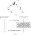
- FIG. 1 is a diagram of an architecture of a communication system to which a method for reporting channel state information is applicable according to an embodiment of this application.
- the communication system includes first apparatuses (101a and 101b) and a second apparatus 102.
- the second apparatus 102 may communicate with both the first apparatus 101a and the first apparatus 101b.
- the second apparatus 102 is a device that sends data, and the first apparatuses (101a and 101b) each is a device that receives data.
- the second apparatus 102 may be a network device or a terminal device, and the first apparatuses (101a and 101b) each may be a network device or a terminal device.
- the first apparatuses (101a and 101b) are network devices, and the second apparatus 102 is a network device.
- the first apparatuses (101a and 101b) are terminal devices, and the second apparatus 102 is a network device.
- the first apparatuses (101a and 101b) are terminal devices, and the second apparatus 102 is a terminal device.
- the network device is a device that is located on a network side of the communication system and that has a wireless transceiver function, or a chip or a chip system that can be disposed in the device.
- the network device includes but is not limited to: an access point (access point, AP), for example, a home gateway, a router, a server, a switch, or a bridge, in a wireless fidelity (wireless fidelity, Wi-Fi) system, an evolved NodeB (evolved NodeB, eNB), a radio network controller (radio network controller, RNC), a NodeB (NodeB, NB), a base station controller (base station controller, BSC), a base transceiver station (base transceiver station, BTS), a home base station (for example, a home evolved NodeB, a home NodeB, HNB), a baseband unit (baseband unit, BBU), a wireless relay node, a wireless backhaul node, a transmission point (transmission
- the network device may alternatively be a gNB or a transmission point (TRP or TP) in a 5G, for example, new radio (new radio, NR) system, or one antenna panel or a group of antenna panels (including a plurality of antenna panels) of a base station in a 5G system.
- the network device may alternatively be a network node, for example, a baseband unit (BBU) or a distributed unit (distributed unit, DU), that constitutes a gNB or a transmission point, a road side unit (road side unit, RSU) having a base station function, or the like.
- BBU baseband unit
- DU distributed unit
- the terminal device is a terminal that accesses the communication system and that has a wireless transceiver function, or a chip or a chip system that can be disposed in the terminal.
- the terminal device may also be referred to as an access terminal, a subscriber unit, a subscriber station, a mobile station, a remote station, a remote terminal, a mobile device, a user terminal, a terminal, a wireless communication device, a user agent, or a user apparatus.
- the first apparatus in embodiments of this application may be a mobile phone (mobile phone), a tablet computer (Pad), a computer having a wireless transceiver function, a virtual reality (virtual reality, VR) first apparatus, an augmented reality (augmented reality, AR) first apparatus, a wireless terminal in industrial control (industrial control), a wireless terminal in self-driving (self-driving), a wireless terminal in remote medical (remote medical), a wireless terminal in a smart grid (smart grid), a wireless terminal in transportation safety (transportation safety), a wireless terminal in a smart city (smart city), a wireless terminal in a smart home (smart home), a vehicle-mounted terminal, an RSU having a terminal function, or the like.
- a virtual reality (virtual reality, VR) first apparatus an augmented reality (augmented reality, AR) first apparatus
- a wireless terminal in industrial control industrial control
- a wireless terminal in self-driving self-driving
- a wireless terminal in remote medical remote medical
- the first apparatus in this application may alternatively be a vehicle-mounted module, a vehicle-mounted assembly, a vehicle-mounted component, a vehicle-mounted chip, or a vehicle-mounted unit that is disposed in a vehicle as one or more components or units.
- the vehicle may implement the method for reporting channel state information in this application by using the vehicle-mounted module, the vehicle-mounted assembly, the vehicle-mounted component, the vehicle-mounted chip, or the vehicle-mounted unit that is disposed in the vehicle.
- the method for reporting channel state information provided in embodiments of this application is applicable to any two nodes shown in FIG. 1 , for example, the first apparatus and the second apparatus.
- the method for reporting channel state information is applicable to any two nodes shown in FIG. 1 , for example, the first apparatus and the second apparatus.
- the method for reporting channel state information is applicable to any two nodes shown in FIG. 1 , for example, the first apparatus and the second apparatus.
- the method for reporting channel state information provided in embodiments of this application is applicable to any two nodes shown in FIG. 1 , for example, the first apparatus and the second apparatus.
- the method for reporting channel state information provided in embodiments of this application is applicable to any two nodes shown in FIG. 1 , for example, the first apparatus and the second apparatus.
- the following method embodiments Details are not described herein.
- FIG. 1 is merely a simplified diagram used as an example for ease of understanding.
- the communication system may further include other second apparatus and/or other first apparatuses not drawn in FIG. 1 .
- FIG. 2 , FIG. 3 , and FIG. 5 to FIG. 7 are schematic flowcharts of method embodiments of this application, and show detailed communication steps or operations of the method. However, these steps or operations are merely examples. In embodiments of this application, other operations or variations of the operations in FIG. 2 , FIG. 3 , and FIG. 5 to FIG. 7 may be alternatively performed. In addition, the steps in FIG.
- FIG. 2 , FIG. 3 , and FIG. 5 to FIG. 7 may be performed in a sequence different from that shown in FIG. 2 , FIG. 3 , and FIG. 5 to FIG. 7 , and it is possible that not all the operations in FIG. 2 , FIG. 3 , and FIG. 5 to FIG. 7 need to be performed.
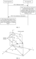
- FIG. 2 is a schematic flowchart of a method for reporting channel state information according to an embodiment of this application.
- the method for reporting channel state information is applicable to communication between the second apparatus and the first apparatus shown in FIG. 1 .
- the method for reporting channel state information includes the following steps.
- S201 A second apparatus sends a reference signal.
- a first apparatus receives the reference signal.
- the reference signal may be a CSI-RS (where, for example, the second apparatus is a network device, and the first apparatus is a terminal device) or a channel sounding reference signal (sounding reference signal, SRS) (where, for example, the first apparatus is a terminal device, and the second apparatus is a network device).
- the reference signal may alternatively be another signal, such as a cell-specific reference signal (cell-specific reference signal, CRS), an SSB, a DMRS, or a tracking reference signal (tracking reference signal, TRS). This is not limited in this application.
- the first apparatus determines first indication information based on the reference signal.
- the first indication information is for constructing a first covariance matrix corresponding to a channel matrix.
- the channel matrix indicates CSI of a transmission channel between the first apparatus and the second apparatus.
- the first covariance matrix corresponding to the channel matrix may include one or more of the following: a first joint space-frequency covariance matrix corresponding to the channel matrix, a first space-domain covariance matrix corresponding to the channel matrix, and a first frequency-domain covariance matrix corresponding to the channel matrix.
- the channel matrix may be determined by the first apparatus based on the received reference signal (for example, a CSI-RS).
- the channel matrix may have M ⁇ N dimensions.
- M ⁇ 1, N ⁇ 1, and both M and N are integers.
- M is a quantity of transmit antenna ports of the second apparatus, and N is a quantity of frequency domain units used by the second apparatus to transmit the reference signal.
- the frequency domain unit may be a subcarrier (subcarrier), a resource block (resource block, RB), or a subband (subband).
- indicate may include direct indication and indirect indication.
- the indication information may directly indicate A or indirectly indicate A, but it does not indicate that the indication information definitely carries A.
- Information indicated by indication information is referred to as to-be-indicated information.
- there are a plurality of manners of indicating the to-be-indicated information for example, but not limited to, the following manners:
- the to-be-indicated information is directly indicated, for example, the to-be-indicated information or an index of the to-be-indicated information is indicated.
- the to-be-indicated information may be indirectly indicated by indicating other information, and there is an association relationship between the other information and the to-be-indicated information.
- only a part of the to-be-indicated information may be indicated, and the other part of the to-be-indicated information is known or pre-agreed on.
- specific information may alternatively be indicated by using an arrangement sequence of a plurality of pieces of information that are pre-agreed on (for example, stipulated in a protocol), to reduce indication overheads to some extent.
- a common part of all the pieces of information may be further identified and indicated in a unified manner, to reduce indication overheads caused by separately indicating same information.
- a precoding matrix includes precoding vectors, and the precoding vectors in the precoding matrix may have a same part in terms of composition or other attributes.
- specific indication manners may alternatively be various existing indication manners, for example, but not limited to, the foregoing indication manners and various combinations thereof.
- the various indication manners refer to the conventional technology. Details are not described in this specification. It can be learned from the foregoing descriptions that, for example, when a plurality of pieces of information of a same type need to be indicated, different information may be indicated in different manners.
- a required indication manner may be selected based on a specific requirement.
- the selected indication manner is not limited in embodiments of this application. In this way, the indication manner in embodiments of this application is to be understood as covering various methods that can enable a to-be-indicated party to learn of to-be-indicated information.
- the to-be-indicated information may be sent as a whole, or may be divided into a plurality of pieces of sub-information for sending separately.
- sending periodicities and/or sending occasions of these pieces of sub-information may be the same or different.
- a specific sending method is not limited in this application.
- the sending periodicities and/or the sending occasions of these pieces of sub-information may be predefined, for example, predefined according to a protocol, or may be configured by a transmitting end device by sending configuration information to a receiving end device.
- the configuration information may include one or a combination of at least two of radio resource control signaling, media access control (media access control, MAC) layer signaling, and physical layer signaling.
- the radio resource control signaling includes, for example, radio resource control (radio resource control, RRC) signaling.
- the MAC layer signaling includes, for example, a MAC control element (control element, CE).
- the physical layer signaling includes, for example, downlink control information (downlink control information, DCI).
- That the first apparatus determines first indication information based on the reference signal may include step 2.1 and step 2.2.
- Step 2.1 The first apparatus determines the channel matrix based on the reference signal.
- Step 2.2 The first apparatus determines the first indication information based on the channel matrix.
- the first indication information indicates a superposition coefficient and a codebook vector, and the superposition coefficient and the codebook vector are for determining the first covariance matrix.
- the first covariance matrix is a covariance matrix corresponding to the channel matrix constructed based on the first indication information.
- the first covariance matrix and an actual covariance matrix corresponding to the channel matrix may satisfy a preset optimization model.
- the preset optimization model may include the following formula (1) and formula (2).
- the preset optimization model may be determined according to the following formula (1) and formula (2): min ⁇ l R ⁇ ⁇ l ⁇ l w l w l H F ; s . t . L ⁇ L max ; min represents taking a minimum value, "
- ⁇ l is an l th superposition coefficient
- w l is an l th codebook vector
- w l H is a conjugate transpose of w l
- s. t. is a constraint
- L is a channel multi-path quantity
- L max is a maximum value of L
- both L and L max are integers greater than 0.
- the first apparatus may obtain corresponding ⁇ l and w l by using the foregoing optimization model, so that an error between the first covariance matrix and the actual covariance matrix corresponding to the channel matrix is minimized.
- the first indication information may be determined based on a solution result of the preset optimization model.
- a dimension of R is related to a type of R .
- R is an actual joint space-frequency covariance matrix corresponding to the channel matrix
- R is a matrix of MN ⁇ MN.
- R is an actual space-domain covariance matrix corresponding to the channel matrix
- R is a matrix of M ⁇ M .
- R is an actual frequency-domain covariance matrix corresponding to the channel matrix
- R is a matrix of N ⁇ N.
- the superposition coefficient may be a complex number
- the codebook vector may be a basis vector.
- the basis vector may be a vector including a row of elements or a column of elements of a basis.
- the basis may include one or more of the following: a space-domain basis, a frequency-domain basis, a joint space-frequency basis, a basis including a steering vector, a basis including a phase change vector, or a basis determined based on a steering vector and a phase change vector.
- the superposition coefficient in the solution result of the preset optimization model is a superposition coefficient ⁇ l
- the codebook vector is w ⁇ l
- the superposition coefficient indicated by the first indication information may be the superposition coefficient ⁇ l
- the codebook vector indicated by the first indication information is w ⁇ l
- the superposition coefficient ⁇ l is obtained by quantizing the superposition coefficient ⁇ l .
- step 2.2 For an implementation principle of step 2.2, refer to step 3.2, step 5.2, step 6.2, or step 7.2 in the following method embodiments. Details are not described herein.
- S203 The first apparatus sends the first indication information.
- the second apparatus receives the first indication information.
- the first indication information may be carried on a physical uplink control channel (physical uplink control channel, PUCCH) or a physical uplink shared channel (physical uplink shared channel, PUSCH).
- PUCCH physical uplink control channel
- PUSCH physical uplink shared channel
- S203 For a specific implementation principle of S203, refer to S303, S503, S603, or S703 in the following method embodiments. Details are not described herein.
- the first apparatus sends, to the second apparatus, the first indication information for constructing the first covariance matrix corresponding to the channel matrix, so that transmission of a large amount of information directly for restoring the channel state information can be avoided, thereby reducing feedback overheads and improving CSI feedback efficiency.
- the second apparatus may determine, based on the first indication information, the first covariance matrix corresponding to the channel matrix, and determine, based on the covariance matrix corresponding to the channel matrix, an eigen basis and a long periodicity coefficient corresponding to the eigen basis. Further, the second apparatus may combine the eigen basis and the long periodicity coefficient corresponding to the eigen basis with a short periodicity coefficient, to restore the complete channel state information.
- the first apparatus may process and report, in a joint space-frequency domain, the first indication information related to restoring the channel state information.
- the first apparatus may send, to the second apparatus, the first indication information for determining the first joint space-frequency covariance matrix.
- the method for reporting channel state information includes the following steps.
- S301 A second apparatus sends a reference signal.
- a first apparatus receives the reference signal.
- the first apparatus determines first indication information based on the reference signal.
- the first indication information is for constructing a first joint space-frequency covariance matrix corresponding to a channel matrix.
- the first indication information indicates a superposition coefficient and a codebook vector
- the superposition coefficient and the codebook vector are for determining the first joint space-frequency covariance matrix.
- the first joint space-frequency covariance matrix is a matrix approximate to an actual joint space-frequency covariance matrix corresponding to the channel matrix.
- the first covariance matrix described in S202 is correspondingly the first joint space-frequency covariance matrix.
- That the first apparatus determines first indication information based on the reference signal may include step 3.1 and step 3.2.
- Step 3.1 The first apparatus determines the channel matrix based on the reference signal.
- step 3.1 For an implementation principle of step 3.1, refer to related descriptions of step 2.1. Details are not described herein again.
- Step 3.2 The first apparatus determines the first indication information based on the channel matrix.
- Step 3.2 may include step 3.2-1 to step 3.2-3.
- Step 3.2-1 The first apparatus determines a channel column vector based on the channel matrix.
- H is the channel matrix, where H ⁇ C M ⁇ N .
- C represents a complex number.
- M is a quantity of antenna ports of the second apparatus, and N is a quantity of frequency units.
- C M ⁇ N represents a matrix with M ⁇ N dimensions.
- S is a space-domain basis, where S ⁇ C M ⁇ L 0 .
- L 0 is a channel multi-path quantity.
- C M ⁇ L 0 represents a matrix with M ⁇ L 0 dimensions.
- C is a diagonal matrix, where C ⁇ C L 0 ⁇ L 0 .
- C L 0 ⁇ L 0 represents a matrix with L 0 ⁇ L 0 dimensions.
- F is a frequency-domain basis, where F ⁇ C N ⁇ L 0 .
- C N ⁇ L 0 represents a matrix with N ⁇ L 0 dimensions.
- F H is a conjugate transpose matrix of F .
- h is the channel column vector, and a dimension of h is MN ⁇ 1.
- F * is a conjugate matrix of F .
- ⁇ represents a Khatri-Rao product.
- diag ( ) represents constructing a diagonal matrix, and c is a vector including a diagonal element of C .
- ⁇ represents a Kronecker (Kronecker) product.
- C MN ⁇ 1 represents a matrix with MN ⁇ 1 dimensions.
- F * ⁇ S [: ,l 0 ] represents a column vector including an l 0 th column of ( F * ⁇ S ) .
- F (: ,l 0 ) represents a column vector including an l 0 th column of F .
- [ F (:, l 0 )]* represents a conjugation of F (:, l 0 ) .
- S (:, l 0 ) represents a column vector including an l 0 th column of S . 0 ⁇ l 0 ⁇ L 0 .
- M and N are both positive integers.
- Step 3.2-2 The first apparatus determines, based on the channel column vector, the actual joint space-frequency covariance matrix corresponding to the channel matrix.
- the actual joint space-frequency covariance matrix corresponding to the channel matrix is an inter-polarization average joint space-frequency covariance matrix R h .
- the channel column vector and the actual joint space-frequency covariance matrix corresponding to the channel matrix satisfy a relationship shown in the following formula (7):
- R h is the inter-polarization average joint space-frequency covariance matrix corresponding to the channel matrix.
- h + is a channel column vector corresponding to a positive polarization direction (which is also referred to as a first polarization direction)
- h - is a channel column vector corresponding to a negative polarization direction (which is also referred to as a second polarization direction).
- h + H is a conjugate transpose of h +
- h ⁇ H is a conjugate transpose of h - .
- Step 3.2-3 The first apparatus determines the first indication information based on the actual joint space-frequency covariance matrix corresponding to the channel matrix.
- the first joint space-frequency covariance matrix and the actual joint space-frequency covariance matrix corresponding to the channel matrix satisfy a preset first optimization model.
- first optimization model For an implementation principle of the first optimization model, refer to related descriptions of the following formula (13) and formula (14). Details are not described herein.
- the actual covariance matrix R corresponding to the channel matrix in the foregoing formula (1) is correspondingly the actual joint space-frequency covariance matrix R h .
- the superposition coefficient may be a first superposition coefficient indicating a feature, for example, an amplitude and/or a phase, of an angle-delay power spectrum.
- the first superposition coefficient may be obtained by sampling the angle-delay power spectrum, or may be obtained by quantizing a sampling result of the angle-delay power spectrum.
- the codebook vector may be a vector determined based on a steering vector and a phase change vector that correspond to multiple paths. The following further describes step 3.2-3 by using a dual-polarized antenna array as an example.
- ⁇ l 0 is a pitch angle of an l 0 th path in multiple paths.
- ⁇ l 0 is a horizontal angle of the l 0 th path in the multiple paths.
- e ( ⁇ l 0 , ⁇ l 0 ) is a steering vector corresponding to a multi-path angle ( ⁇ l 0 , ⁇ l 0 ).
- ⁇ l 0 is a delay of the l 0 th path in the multiple paths.
- e ( ⁇ l 0 ) is a phase change vector corresponding to the delay ⁇ l 0 .
- e * ( ⁇ l 0 ) is a conjugation of e ( ⁇ l 0 ).
- the pitch angle of the path may refer to an angle between the path and a first plane, where the first plane is a plane perpendicular to a plane on which the antenna panel (antenna panel) is located.
- the horizontal angle of the path may refer to an angle between the path and a second plane, where the second plane is a plane perpendicular to both the plane on which the antenna panel is located and the first plane.
- the following uses a three-dimensional coordinate axis as an example for description. As shown in FIG.
- an x-axis, a y -axis, and a z -axis are perpendicular to each other, and a plane on which an antenna panel is located in a uniform planar array is parallel to a plane formed by the y -axis and the z-axis.
- a pitch angle of a path is an angle between the path and a plane on which the x-axis and the z-axis are located
- a horizontal angle of the path is an angle between a projection of the path on a plane xOy and the x-axis.
- the actual joint space-frequency covariance matrix corresponding to the channel matrix may further satisfy a relationship shown in the following formula (10) and formula (11):
- R ⁇ h 1 2 E h + h + H + h ⁇ h ⁇ H ;
- an l 0 th codebook vector is determined based on the steering vector corresponding to the multi-path angle of the l 0 th path and the phase change vector corresponding to the delay of the l 0 th path.
- l in the formula (1) corresponds to l 0 .
- the first optimization model may include the following formula (13) and formula (14).
- the first optimization model may be determined according to the following formula (13) and formula (14): min ⁇ l 0 R ⁇ h ⁇ ⁇ l 0 ⁇ l 0 e H ⁇ l 0 ⁇ l 0 ⁇ e * ⁇ l 0 e T ⁇ l 0 F ; s . t . ⁇ l 0 > 0 L 0 ⁇ L max FS ;
- ⁇ l 0 is an l 0 th first superposition coefficient (namely, a first superposition coefficient corresponding to the l 0 th path). 0 ⁇ l 0 ⁇ L 0 , and l 0 is an integer.
- L 0 is a channel multi-path quantity.
- L max FS is a maximum value of L 0 . Both L 0 and L max FS are integers greater than 0.
- the first apparatus may obtain corresponding ⁇ l 0 , e ( ⁇ l 0 , ⁇ l 0 ), and e ( ⁇ l 0 ) by using the foregoing first optimization model, so that the error between the first joint space-frequency covariance matrix and the actual joint space-frequency covariance matrix corresponding to the channel matrix is minimized.
- the first indication information may be determined based on a solution result of the preset second optimization model.
- a multi-path angle is ( ⁇ l 0 , ⁇ l 0 )
- a steering vector is a first steering vector e ( ⁇ l 0 , ⁇ l 0 )
- a delay is ⁇ l 0
- a phase change vector corresponding to the delay ⁇ l 0 is a first phase change vector e ( ⁇ l 0 )
- a first superposition coefficient representing a feature of an angle-delay power spectrum corresponding to ( ⁇ l 0 , ⁇ 0 ) and ⁇ l 0 is a first joint space-frequency superposition coefficient ⁇ l 0 (namely, the foregoing superposition coefficient ⁇ l ).
- the superposition coefficient ⁇ l indicated by the first indication information is a second joint space-frequency superposition coefficient ⁇ l 0 .
- the second joint space-frequency superposition coefficient ⁇ l 0 is a coefficient obtained by quantizing the first joint space-frequency superposition coefficient ⁇ l 0 , and the second joint space-frequency superposition coefficient ⁇ l 0 may also represent the feature of the angle-delay power spectrum corresponding to ( ⁇ l 0 , ⁇ l 0 ) and ⁇ l 0 It is to be noted that ( ⁇ l 0 , ⁇ l 0 ) may be an unquantized or quantized multi-path angle, and ⁇ l 0 may be an unquantized or quantized delay.
- the first indication information indicates the first steering vector e ( ⁇ l 0 , ⁇ l 0 ), the first phase change vector e ( ⁇ l 0 ), and the second joint space-frequency superposition coefficient ⁇ l 0 .
- the codebook vector indicated by the first indication information corresponds to the first steering vector e ( ⁇ l 0 , ⁇ l 0 ) and the first phase change vector e ( ⁇ l 0 )
- the superposition coefficient namely, the superposition coefficient ⁇ l
- the first indication information indicates the multi-path angle ( ⁇ l 0 , ⁇ l 0 ), the delay ⁇ l 0 , and the second joint space-frequency superposition coefficient ⁇ l 0 .
- the codebook vector indicated by the first indication information corresponds to the multi-path angle ( ⁇ l 0 , ⁇ l 0 ) and the delay ⁇ l 0
- the superposition coefficient namely, the superposition coefficient ⁇ l ⁇
- the steering vector e ( ⁇ l 0 , ⁇ l 0 ) and the phase change vector e ( ⁇ l 0 ) are determined based on antenna form information.
- the method for reporting channel state information shown in FIG. 3 further includes the following step 3.3 to step 3.5.
- Step 3.3 The second apparatus sends information indicating an antenna array form, and the first apparatus receives the information.
- the information includes: a horizontal element distance, a vertical element distance, a quantity of single-polarized horizontal elements, and a quantity of single-polarized vertical elements.
- Step 3.4 The first apparatus determines the steering vector e ( ⁇ l 0 , ⁇ l 0 ) based on the information indicating the antenna array form.
- e h ( ⁇ l 0 , ⁇ l 0 ) is a horizontal steering vector
- e v ( ⁇ l 0 ) is a vertical steering vector
- D h is a horizontal element distance
- D v is a vertical element distance
- M h is a quantity of single-polarized horizontal elements
- M v is a quantity of single-polarized vertical elements
- Step 3.5 The first apparatus determines the phase change vector e ( ⁇ l 0 ) based on the information indicating the antenna array form.
- step 3.5 may be performed before step 3.4; or one or more of step 3.3 to step 3.5 may be performed before step 3.2-3.
- S303 The first apparatus sends the first indication information.
- the second apparatus receives the first indication information.
- the first indication information may be carried on a PUCCH or a PUSCH.
- the first apparatus sends the first indication information based on a first periodicity
- the second apparatus receives the first indication information based on the first periodicity
- the second apparatus determines, based on the first indication information, the first joint space-frequency covariance matrix corresponding to the channel matrix.
- the first joint space-frequency covariance matrix is a joint space-frequency covariance matrix corresponding to the channel matrix determined and constructed based on the first indication information.
- the first indication information indicates the superposition coefficient ⁇ l 0 and the codebook vector w ⁇ l 0 is used as an example.
- R ⁇ h is the first joint space-frequency covariance matrix, ⁇ l 0 , is the superposition coefficient, w ⁇ l 0 is the codebook vector, and w ⁇ l 0 H is a conjugate transpose of w ⁇ l 0 .
- the first indication information indicates the first steering vector e ( ⁇ l 0 , ⁇ 0 ), the first phase change vector e ( ⁇ l 0 ), and the second joint space-frequency superposition coefficient ⁇ l 0
- the codebook vector indicated by the first indication information corresponds to the first steering vector e ( ⁇ l 0 , ⁇ l 0 ) and the first phase change vector e ( ⁇ 0 )
- the superposition coefficient corresponds to the second joint space-frequency superposition coefficient ⁇ l 0
- the first joint space-frequency covariance matrix may satisfy a relationship shown in the following formula (20):
- R ⁇ h ⁇ l 0 ⁇ ⁇ l 0 e ⁇ ⁇ l 0 ⁇ ⁇ l 0 e H ⁇ ⁇ l 0 ⁇ ⁇ l 0 ⁇ e * ⁇ ⁇ l 0 e T
- e H ( ⁇ l 0 , ⁇ l 0 ) is a conjugate transpose of e ( ⁇ l 0 , ⁇ l 0 ), e * ( ⁇ l 0 ) is a conjugation of e ( ⁇ l 0 ) , and e T ( ⁇ 0 ) is a transpose of e ( ⁇ l 0 ) .
- the second apparatus may first determine, according to the formula (15) to the formula (17), the steering vector e ( ⁇ l 0 , ⁇ 0 ) corresponding to the multi-path angle ( ⁇ l 0 , ⁇ l 0 ), and determine the phase change vector e ( ⁇ l 0 ) according to the formula (18). Then, the second apparatus determines the first joint space-frequency covariance matrix according to the formula (20).
- the first apparatus determines the first indication information for constructing the first joint space-frequency covariance matrix, and sends the first indication information to the second apparatus, so that reporting of a large amount of information, for example, a superposition coefficient corresponding to a joint space-frequency eigen basis, directly for restoring the channel state information can be avoided.
- the second apparatus may determine, based on the first indication information, the first joint space-frequency covariance matrix corresponding to the channel matrix, and determine the eigen basis based on the first joint space-frequency covariance matrix corresponding to the channel matrix, to reduce an amount of data that is fed back, so that the feedback overheads can be reduced, and the CSI feedback efficiency is improved.
- the first apparatus may report a part of superposition coefficients, for example, the superposition coefficient indicated by the first indication information, to the second apparatus based on a long periodicity (namely, the first periodicity), and report a part of the superposition coefficients, for example, the following first feedback coefficient, to the second apparatus based on a short periodicity (namely, a second periodicity).
- the second apparatus may determine the complete channel state information based on the first indication information and the first feedback coefficient.
- duration of the first periodicity is greater than duration of the second periodicity.
- duration of the first periodicity is a plurality of integral multiples of the duration of the second periodicity. It is to be noted that reporting based on the short periodicity is reporting based on one time of reference signal measurement, and reporting based on the long periodicity is reporting based on a plurality of times of reference signal measurement. A specific quantity of times is not specifically limited in this application.
- the method for reporting channel state information provided in FIG. 3 may further include step 3.6.
- Step 3.6 The first apparatus sends second indication information.
- the second apparatus receives the second indication information.
- the second indication information indicates the first feedback coefficient.
- the first feedback coefficient is determined based on a first decomposition result of the first joint space-frequency covariance matrix and the channel matrix.
- the first decomposition result is obtained by decomposing the first joint space-frequency covariance matrix according to a first decomposition rule.
- the first decomposition rule may include an arrangement sequence, for example, descending order or ascending order, of elements in a diagonal matrix obtained by decomposing the first joint space-frequency covariance matrix, and a type of elements in a 1 st row of a joint space-frequency eigen basis obtained by decomposing the first joint space-frequency covariance matrix, for example, a positive real number.
- the following uses an example to describe a principle of obtaining the first feedback coefficient by the first apparatus.
- the first indication information indicates the first steering vector e ( ⁇ l 0 , ⁇ l 0 ), the first phase change vector e ( ⁇ l 0 ), and the second joint space-frequency superposition coefficient ⁇ l 0 , to be specific, the codebook vector indicated by the first indication information corresponds to the first steering vector e ( ⁇ 0 , ⁇ l 0 ) and the first phase change vector e ( ⁇ l 0 ), and the superposition coefficient corresponds to the second joint space-frequency superposition coefficient ⁇ l 0 .
- the first indication information indicates the multi-path angle ( ⁇ l 0 , ⁇ l 0 ), the delay ⁇ l 0 , and the second joint space-frequency superposition coefficient ⁇ l 0 , to be specific, the codebook vector indicated by the first indication information corresponds to the multi-path angle ( ⁇ l 0 , ⁇ l 0 ) and the delay ⁇ 0 , the superposition coefficient corresponds to the second joint space-frequency superposition coefficient ⁇ l 0 , and the channel matrix determined by the first apparatus is H .
- the method for reporting channel state information provided in FIG. 3 may further include step 3.6-1 to step 3.6-5.
- Step 3.6-1 The first apparatus determines the first joint space-frequency covariance matrix based on the first indication information.
- the first joint space-frequency covariance matrix and the first indication information satisfy the relationship shown in the foregoing formula (19) or formula (20).
- Step 3.6-2 The first apparatus decomposes the first joint space-frequency covariance matrix, for example, performs singular value decomposition (singular value decomposition, SVD) or eigen value decomposition (eigen value decomposition, EVD), to obtain the joint space-frequency eigen basis.
- U is the joint space-frequency eigen basis of the first joint space-frequency covariance matrix
- ⁇ is a diagonal matrix obtained by performing SVD decomposition on the first joint space-frequency covariance matrix
- U H is a conjugate transpose of U .
- an eigen vector (column vector) with large energy may be selected from the joint space-frequency eigen basis to form a valid joint space-frequency eigen basis.
- a quantity of selected columns of the eigen vectors may be determined based on the energy of the eigen vectors, and an eigen vector that ranks first in the columns is preferentially selected. For details, refer to the following step 3.6-3.
- Step 3.6-3 The first apparatus determines a matrix including first P columns of the joint space-frequency eigen basis U as a valid joint space-frequency eigen basis ⁇ .
- Step 3.6-4 The first apparatus determines a joint space-frequency short periodicity feedback coefficient based on the valid joint space-frequency eigen basis ⁇ , where the joint space-frequency short periodicity feedback coefficient is a projection coefficient of the channel in a joint space-frequency domain.
- C 21 is the joint space-frequency short periodicity feedback coefficient
- Step 3.6-5 The first apparatus quantizes a part or all of elements of the joint space-frequency short periodicity feedback coefficient, to obtain the first feedback coefficient ⁇ 21 .
- the first indication information may further indicate a first quantized vector obtained by quantizing a 1 st row of elements of first P columns in the joint space-frequency eigen basis of the first decomposition result.
- P is a positive integer.
- the first quantized vector û is obtained by the first apparatus by quantizing the 1 st row of the valid joint space-frequency eigen basis ⁇ .
- the method provided in FIG. 3 may further include: The second apparatus determines the valid joint space-frequency eigen basis of the first joint space-frequency covariance matrix according to the first decomposition rule.
- step 3.6-1 For a principle of determining the valid joint space-frequency eigen basis by the second apparatus, refer to step 3.6-1 to step 3.6-3. Details are not described herein again.
- the first indication information further indicates the first quantized vector obtained by quantizing a 1 st row of elements of the first P columns in the joint space-frequency eigen basis obtained by decomposing the first joint space-frequency covariance matrix.
- P is a positive integer.
- the joint space-frequency eigen basis may be combined with the first feedback coefficient, namely, a short periodicity coefficient, so that the second apparatus can restore the complete channel state information.
- the second apparatus determines a valid joint space-frequency eigen basis of the first joint space-frequency covariance matrix according to the first decomposition rule may include: The second apparatus determines the valid joint space-frequency eigen basis of the first joint space-frequency covariance matrix according to the first decomposition rule and based on the first quantized vector.
- the second apparatus determines the channel state information, for example, a channel column vector corresponding to the channel matrix, based on the valid joint space-frequency eigen basis and the first feedback coefficient.
- h' is the channel column vector determined by the second apparatus, or may be referred to as channel state information determined by the second apparatus.
- the first apparatus may process and report, in space domain, the first indication information related to restoring the channel state information.
- the first apparatus may send, to the second apparatus, first indication information for determining a first space-domain covariance matrix.
- the method for reporting channel state information includes the following steps.
- S501 A second apparatus sends a reference signal.
- a first apparatus receives the reference signal.
- the first apparatus determines first indication information based on the reference signal.
- the first indication information is for constructing a first space-domain covariance matrix corresponding to a channel matrix.
- the first indication information indicates a superposition coefficient and a codebook vector.
- the superposition coefficient includes a second superposition coefficient indicating a feature, for example, an amplitude and/or a phase, of an angle power spectrum.
- the second superposition coefficient may be obtained by sampling the angle power spectrum, or may be obtained by quantizing a sampling result of the angle power spectrum.
- the codebook vector includes second information indicating an angle. The second superposition coefficient and the second information are for determining the first space-domain covariance matrix.
- That the first apparatus determines first indication information based on the reference signal may include step 5.1 and step 5.2.
- Step 5.1 The first apparatus determines the channel matrix based on the reference signal.
- step 5.1 For an implementation principle of step 5.1, refer to related descriptions of step 2.1. Details are not described herein again.
- Step 5.2 The first apparatus determines the first indication information based on the channel matrix.
- the first space-domain covariance matrix is a matrix approximate to an actual space-domain covariance matrix corresponding to the channel matrix, and the first space-domain covariance matrix and the actual space-domain covariance matrix satisfy a preset second optimization model.
- the actual covariance matrix R corresponding to the channel matrix in the foregoing formula (1) is correspondingly an actual space-domain covariance matrix R h S .
- the second information may be indicated by using a steering vector corresponding to each multi-path angle (an angle of each of multiple paths), or a multi-path angle of each of multiple paths.
- the first indication information may indicate the second superposition coefficient and the steering vector corresponding to each multi-path angle.
- the first indication information may indicate the second superposition coefficient and the multi-path angle of each of the multiple paths.
- the second optimization model may include a formula (24) and a formula (25).
- the second optimization model may be determined according to the formula (24) and the formula (25): min ⁇ l 1 S R h S ⁇ ⁇ l 1 ⁇ l 1 S e ⁇ l 1 ⁇ l 1 e H ⁇ l 1 ⁇ l 1 F ; s . t .
- ⁇ l 1 S > 0 L 1 ⁇ L max S ;
- R h S is the actual space-domain covariance matrix corresponding to the channel matrix;
- ⁇ l 1 S is an l 1 th second superposition coefficient,
- e ( ⁇ l 1 , ⁇ l 1 ) is a steering vector corresponding to an l 1 th multi-path angle,
- e H ( ⁇ l 1 , ⁇ l 1 ) is a conjugate transpose of e ( ⁇ l 1 , ⁇ l 1 )
- L 1 is a channel multi-path quantity in space domain,
- L max S is a maximum value of L 1
- both L 1 and L max S are integers greater than 0, 0 ⁇ l 1 ⁇ L 1
- l 1 is an integer.
- the first apparatus may obtain corresponding R h S and e ( ⁇ l 1 , ⁇ 1 ) by using the foregoing second optimization model, so that an error between the first space-domain covariance matrix and the actual space-domain covariance matrix corresponding to the channel matrix is minimized.
- the first indication information may be determined based on a solution result of the preset second optimization model.
- the actual space-domain covariance matrix corresponding to the channel matrix may be determined based on the channel matrix.
- the actual space-domain covariance matrix corresponding to the channel matrix satisfies a relationship shown in the following formula (26):
- R h S 1 2 E H + H + H + H + H ⁇ H ⁇ H ;
- R h S is the actual space-domain covariance matrix corresponding to the channel matrix
- H + is a channel matrix corresponding to a positive-polarized antenna
- ( H + ) H is a conjugate transpose of H +
- H - is a channel matrix corresponding to a negative-polarized antenna
- ( H - ) H is a conjugate transpose of H - .
- the first indication information may be determined based on a solution result of the preset second optimization model.
- the multi-path angle is ( ⁇ l 1 , ⁇ l 1 )
- the steering vector is a second steering vector e ( ⁇ l 1 , ⁇ l 1 )
- the second superposition coefficient indicating the feature of the angle power spectrum corresponding to ( ⁇ l 1 , ⁇ l 1 ) is a first space-domain superposition coefficient ⁇ ⁇ l 1 S .
- the first indication information indicates the second steering vector e ( ⁇ 1 , ⁇ l 1 ) and a second space-domain superposition coefficient ⁇ ⁇ l 1 S , to be specific, the codebook vector indicated by the first indication information corresponds to the second steering vector e ( ⁇ l 1 , ⁇ l 1 ) , and the superposition coefficient corresponds to the second space-domain superposition coefficient ⁇ ⁇ l 1 S .
- the first indication information indicates the multi-path angle ( ⁇ l 1 , ⁇ l 1 ) and a second space-domain superposition coefficient ⁇ ⁇ l 1 S
- the codebook vector indicated by the first indication information corresponds to the multi-path angle ( ⁇ l 1 , ⁇ l 1 )
- the superposition coefficient corresponds to the second space-domain superposition coefficient ⁇ ⁇ l 1 S .
- the second space-domain superposition coefficient ⁇ ⁇ l 1 S is a coefficient obtained by decomposing the first space-domain superposition coefficient ⁇ ⁇ l 1 S .
- the codebook vector w ⁇ l corresponds to e ( ⁇ l 1 , ⁇ l 1 )
- the superposition coefficient ⁇ l corresponds to the second space-domain superposition coefficient ⁇ ⁇ l 1 S .
- l in the formula (1) corresponds to l 1 . It is to be noted that ( ⁇ l 1 , ⁇ l 1 ) is a quantized multi-path angle.
- S503 The first apparatus sends the first indication information.
- the second apparatus receives the first indication information.
- the first indication information may be carried on a PUCCH or a PUSCH.
- the second apparatus determines, based on the first indication information, the first space-domain covariance matrix corresponding to the channel matrix.
- the first indication information indicates the second steering vector e ( ⁇ l 1 , ⁇ l 1 ) and the second space-domain superposition coefficient ⁇ ⁇ l 1 S , to be specific, the superposition coefficient indicated by the first indication information corresponds to the second space-domain superposition coefficient ⁇ ⁇ l 1 S , and the codebook vector corresponds to the second steering vector e ( ⁇ l 1 , ⁇ l 1 ) .
- the first indication information indicates the multi-path angle ( ⁇ l 1 , ⁇ 1 ) and the second space-domain superposition coefficient ⁇ ⁇ l 1 S , to be specific, the superposition coefficient indicated by the first indication information corresponds to ⁇ ⁇ l 1 S , and the codebook vector corresponds to the multi-path angle ( ⁇ l 1 , ⁇ l 1 ).
- the first space-domain covariance matrix satisfies a relationship of the following formula (27):
- R ⁇ h S ⁇ l ⁇ ⁇ l 1 S e ⁇ ⁇ l 1 ⁇ ⁇ l 1 e H ⁇ ⁇ l 1 ⁇ ⁇ l 1 ;
- R ⁇ h S is the first space-domain covariance matrix, and
- e H ( ⁇ l 1 , ⁇ l 1 ) is a conjugate transpose of e ( ⁇ l 1 , ⁇ l 1 ) .
- the first apparatus feeds back the first indication information for constructing the first space-domain covariance matrix, and sends the first indication information to the second apparatus, so that reporting of a large quantity of coefficients, for example, the superposition coefficient corresponding to the space-domain eigen basis, directly for restoring the channel state information can be avoided.
- the second apparatus may determine, based on the first indication information, the first space-domain covariance matrix corresponding to the channel matrix, and determine the space-domain eigen basis based on the first space-domain covariance matrix corresponding to the channel matrix, to reduce an amount of data that is fed back, so that the feedback overheads can be reduced, and the feedback efficiency is improved.
- the space-domain eigen basis may be combined with a short periodicity feedback coefficient and a frequency-domain eigen basis, so that the second apparatus can restore the complete channel state information.
- the first apparatus may process and report, in frequency domain, the first indication information related to restoring the channel state information.
- the first apparatus may send, to the second apparatus, first indication information for determining a frequency-domain covariance matrix.
- the method for reporting channel state information includes the following steps.
- a second apparatus sends a reference signal to a first apparatus.
- the first apparatus receives the reference signal from the second apparatus.
- the first apparatus determines first indication information based on the reference signal.
- the first indication information is for constructing a first frequency-domain covariance matrix corresponding to a channel matrix.
- the first indication information indicates a superposition coefficient and a codebook vector.
- the superposition coefficient includes a third superposition coefficient indicating a feature, for example, an amplitude and/or a phase, of a delay power spectrum.
- the third superposition coefficient may be obtained by sampling the delay power spectrum, or may be obtained by quantizing a sampling result of the delay power spectrum.
- the codebook vector includes third information indicating a delay. The third superposition coefficient and the third information are for determining the first frequency-domain covariance matrix.
- That the first apparatus determines first indication information based on the reference signal may include step 6.1 and step 6.2.
- Step 6.1 The first apparatus determines the channel matrix based on the reference signal.
- step 6.1 For an implementation principle of step 6.1, refer to related descriptions of step 2.1. Details are not described herein again.
- Step 6.2 The first apparatus determines the first indication information based on the channel matrix.
- the first frequency-domain covariance matrix is a matrix approximate to an actual frequency-domain covariance matrix corresponding to the channel matrix, and the first frequency-domain covariance matrix and the actual frequency-domain covariance matrix satisfy a preset third optimization model.
- the actual covariance matrix R corresponding to the channel matrix in the foregoing formula (1) is correspondingly an actual frequency-domain covariance matrix R h F .
- the third information may be indicated by using a phase change vector corresponding to a delay of each path, or a delay of each path.
- the first indication information may indicate the third superposition coefficient and the phase change vector corresponding to each path.
- the first indication information may indicate the third superposition coefficient and the delay of each path.
- the third optimization model may include a formula (28) and a formula (29).
- the third optimization model may be determined according to the formula (28) and the formula (29): min ⁇ l 2 F R h F ⁇ ⁇ l 2 ⁇ l 2 F e ⁇ l 2 e H ⁇ l 2 F ; s . t .
- ⁇ l 2 F > 0 L 2 ⁇ L max F ;
- R h F is the actual frequency-domain covariance matrix corresponding to the channel matrix;
- ⁇ l 2 F is an l 2 th third superposition coefficient, e ( ⁇ l 2 ) is an l 2 th phase change vector, e H ( ⁇ 2 ) is a conjugate transpose of e ( ⁇ l 2 ) ,
- L 2 is a channel multi-path quantity in frequency domain,
- L max F is a maximum value of L 2 , both L 2 and L max F are integers greater than 0, 0 ⁇ l 2 ⁇ L 2 , and l 2 is an integer.
- the first apparatus determines the channel matrix by measuring the reference signal and obtains R h F , an error between the first frequency-domain covariance matrix and the actual frequency-domain covariance matrix corresponding to the channel matrix can be minimized by using the second optimization model.
- the first indication information may be determined based on a solution result of the preset third optimization model.
- the actual frequency-domain covariance matrix corresponding to the foregoing channel matrix may be determined based on the channel matrix.
- the delay is ⁇ l 2
- a phase change vector corresponding to the delay ⁇ l 2 is a second phase change vector e ( ⁇ l 2 )
- a coefficient representing a feature of a delay power spectrum corresponding to ⁇ l 2 is a first frequency-domain superposition coefficient ⁇ 2 .
- the first indication information indicates the second phase change vector e ( ⁇ l 2 ) and a second frequency-domain superposition coefficient ⁇ ⁇ l 2 F , to be specific, the codebook vector indicated by the first indication information corresponds to the second phase change vector e ( ⁇ l 2 ), and the superposition coefficient corresponds to the second frequency-domain superposition coefficient ⁇ ⁇ l 2 F .
- the first indication information indicates a delay ⁇ l 2 , and a second delay power spectrum ⁇ ⁇ l 2 F , to be specific, the codebook vector indicated by the first indication information corresponds to the delay ⁇ l 2 , and the superposition coefficient corresponds to the second frequency-domain superposition coefficient ⁇ ⁇ l 2 F .
- the second frequency-domain superposition coefficient ⁇ ⁇ l 2 F is a coefficient obtained by decomposing the first frequency-domain superposition coefficient ⁇ l 2 .
- the codebook vector w ⁇ l corresponds to e ( ⁇ 2 )
- the superposition coefficient ⁇ l corresponds to the second frequency-domain superposition coefficient ⁇ ⁇ l 2 F
- l in the formula (1) corresponds to l 2 .
- ⁇ l 2 is a quantized delay.
- S603 The first apparatus sends the first indication information.
- the second apparatus receives the first indication information.
- the first indication information may be carried on a PUCCH or a PUSCH.
- the second apparatus determines, based on the first indication information, the first frequency-domain covariance matrix corresponding to the channel matrix.
- the first frequency-domain covariance matrix satisfies a relationship shown in the following formula (31):
- R ⁇ h F ⁇ l 2 ⁇ ⁇ l 2 F e * ⁇ ⁇ l 2 e T ⁇ ⁇ l 2 ;
- R ⁇ h F is the first frequency-domain covariance matrix.
- e * ( ⁇ l 2 ) is a conjugation of e ( ⁇ l 2 )
- e T ( ⁇ 2 ) is a transpose of e ( ⁇ l 2 ).
- the first apparatus feeds back the first indication information for constructing the first frequency-domain covariance matrix, and sends the first indication information to the second apparatus, so that reporting of a large amount of information, for example, the superposition coefficient corresponding to the frequency-domain eigen basis, directly for restoring the channel state information can be avoided.
- the second apparatus may determine the first frequency-domain covariance matrix based on the first indication information, and determine the frequency-domain eigen basis based on the first frequency-domain covariance matrix corresponding to the channel matrix, to reduce an amount of data that is fed back, so that the feedback overheads can be reduced, and the feedback efficiency is improved.
- the frequency-domain eigen basis may be combined with the space-domain eigen basis and a short periodicity feedback coefficient, so that the second apparatus can restore the complete channel state information.
- the first apparatus may process and report, in both space domain and frequency domain, the first indication information related to restoring the channel state information.
- the first apparatus may send, to the second apparatus, first indication information for determining both a frequency-domain covariance matrix and a space-domain covariance matrix.
- the method for reporting channel state information includes the following steps.
- S701 A second apparatus sends a reference signal.
- a first apparatus receives the reference signal.
- the first apparatus determines first indication information based on the reference signal.
- the first indication information is for constructing a first space-domain covariance matrix corresponding to a channel matrix and a first frequency-domain covariance matrix corresponding to the channel matrix.
- the first indication information may indicate a superposition coefficient and a codebook vector.
- the superposition coefficient may include a second superposition coefficient indicating a feature, for example, an amplitude and/or a phase, of an angle power spectrum and a third superposition coefficient indicating a feature, for example, an amplitude and/or a phase, of a delay power spectrum.
- the second superposition coefficient may be obtained by sampling the angle power spectrum, or may be obtained by quantizing a sampling result of the angle power spectrum.
- the third superposition coefficient may be obtained by sampling the delay power spectrum, or may be obtained by quantizing a sampling result of the delay power spectrum.
- the codebook vector may include second information indicating an angle and third information indicating a delay.
- the second superposition coefficient and the second information are for determining the first space-domain covariance matrix.
- the third superposition coefficient and the third information are for determining the first frequency-domain covariance matrix.
- the first space-domain covariance matrix and an actual space-domain covariance matrix corresponding to the channel matrix satisfy a preset second optimization model, and the first frequency-domain covariance matrix and an actual frequency-domain covariance matrix corresponding to the channel matrix satisfy a preset third optimization model.
- the covariance matrix R corresponding to the channel matrix in the foregoing formula (1) includes the actual space-domain covariance matrix R h S corresponding to the channel matrix and the actual frequency-domain covariance matrix R h F corresponding to the channel matrix.
- the space-domain covariance matrix and the frequency-domain covariance matrix may be fed back.
- the second information, the first space-domain covariance matrix, and the second optimization model refer to related descriptions in S502.
- the third information, the first frequency-domain covariance matrix, and the third optimization model refer to related descriptions in S602. Details are not described herein again.
- That the first apparatus determines first indication information based on the reference signal may include step 7.1 and step 7.2.
- Step 7.1 The first apparatus determines the channel matrix based on the reference signal.
- step 7.1 For an implementation principle of step 7.1, refer to related descriptions of step 2.1. Details are not described herein again.
- Step 7.2 The first apparatus determines the first indication information based on the channel matrix.
- step 7.2 refers to related descriptions of step 5.2 and step 6.2. Details are not described herein again.
- S703 The first apparatus sends the first indication information.
- the second apparatus receives the first indication information.
- the first indication information may be carried on a PUCCH or a PUSCH.
- the first apparatus sends the first indication information based on a third periodicity.
- the second apparatus receives the first indication information based on the third periodicity.
- the second apparatus determines, based on the first indication information, the first space-domain covariance matrix and the first frequency-domain covariance matrix that correspond to the channel matrix.
- S704 may include step 7.3 and step 7.4.
- Step 7.3 The second apparatus determines, based on the first indication information, the first space-domain covariance matrix corresponding to the channel matrix.
- step 7.3 For an implementation principle of step 7.3, refer to related descriptions of S504. Details are not described herein again.
- Step 7.4 The second apparatus determines, based on the first indication information, the first frequency-domain covariance matrix corresponding to the channel matrix.
- step 7.4 For an implementation principle of step 7.4, refer to related descriptions of S604. Details are not described herein again.
- the first apparatus feeds back the first indication information for constructing the first space-domain covariance matrix and the first frequency-domain covariance matrix, and sends the first indication information to the second apparatus, so that reporting of a large amount of information, for example, the superposition coefficient corresponding to the space-domain eigen basis and the superposition coefficient corresponding to the frequency-domain eigen basis, directly for restoring the channel state information can be avoided.
- the first space-domain covariance matrix and the first frequency-domain covariance matrix are determined based on the first indication information from the first apparatus.
- the second apparatus may determine, based on the first indication information, the first space-domain covariance matrix and the first frequency-domain covariance matrix that correspond to the channel matrix, determine the space-domain eigen basis based on the first space-domain covariance matrix corresponding to the channel matrix, and determine the frequency-domain eigen basis based on the first frequency-domain covariance matrix corresponding to the channel matrix, to reduce an amount of data that is fed back, so that the feedback overheads can be reduced, and the feedback efficiency is improved.
- the first apparatus may report a part of the superposition coefficients, for example, the superposition coefficient indicated by the first indication information, to the second apparatus based on a long periodicity (namely, the third periodicity), and report a part of the superposition coefficients, for example, the following second feedback coefficient, to the second apparatus based on a short periodicity (namely, a fourth periodicity).
- the second apparatus may determine the channel state information based on the first indication information and the second feedback coefficient.
- the method for reporting channel state information provided in FIG. 7 may further include: The first apparatus sends third indication information based on the fourth periodicity.
- the second apparatus receives the third indication information based on the fourth periodicity.
- the third indication information indicates the second feedback coefficient, and the fourth periodicity is shorter than a third periodicity.
- the second feedback coefficient is determined based on a second decomposition result of the first space-domain covariance matrix, a third decomposition result of the first frequency-domain covariance matrix, and the channel matrix.
- the second decomposition result is obtained by decomposing the first space-domain covariance matrix according to a second decomposition rule
- the third decomposition result is obtained by decomposing the first frequency-domain covariance matrix according to a third decomposition rule.
- the second decomposition rule may include an arrangement sequence, for example, ascending order or descending order, of elements in a diagonal matrix of the first space-domain covariance matrix, and a type of elements in a 1 st row of a space-domain eigen basis of the first space-domain covariance matrix, for example, a positive real number.
- the third decomposition rule may include an arrangement sequence, for example, ascending order or descending order, of elements in a diagonal matrix of the first frequency-domain covariance matrix, and a type of elements in a 1 st row of a frequency-domain eigen basis of the first frequency-domain covariance matrix, for example, a positive real number.
- a process in which the first apparatus determines the second feedback coefficient includes the following step 7.5 to step 7.8.
- Step 7.5 The first apparatus determines the first space-domain covariance matrix and the first frequency-domain covariance matrix based on the third indication information.
- Step 7.6 The first apparatus performs SVD decomposition on the first space-domain covariance matrix according to the second decomposition rule, to obtain a space-domain eigen basis.
- the first apparatus performs SVD decomposition on the first frequency-domain covariance matrix according to the third decomposition rule, to obtain a frequency-domain eigen basis.
- U S is the space-domain eigen basis
- ⁇ S is a diagonal matrix of the first space-domain covariance matrix
- U S H is a conjugate transpose matrix of U S
- U F is the frequency-domain eigen basis
- ⁇ F is a diagonal matrix of the first frequency-domain covariance matrix
- U F H is a conjugate transpose matrix of U F .
- an eigen vector (column vector) with large energy may be selected from the space-domain eigen basis to form a valid space-domain eigen basis, and an eigen vector (column vector) with large energy may be selected from the frequency-domain eigen basis to form a valid frequency-domain eigen basis.
- an eigen vector (column vector) with large energy may be selected from the frequency-domain eigen basis to form a valid frequency-domain eigen basis.
- Step 7.7 For the space-domain eigen basis U S , select the first D columns of the space-domain eigen basis U S , to obtain the valid space-domain eigen basis ⁇ S , and for the frequency-domain eigen basis U F , select the first D columns of the frequency-domain eigen basis U F , to obtain the valid frequency-domain eigen basis ⁇ F .
- Step 7.8 Determine, based on the valid space-domain eigen basis ⁇ S and the valid frequency-domain eigen basis ⁇ F , a feedback coefficient C 22 in combination with both space domain and frequency domain, and quantize (for example, representing by using a binary number) the short periodicity feedback coefficient in combination with both space domain and frequency domain, to obtain the second feedback coefficient ⁇ 22 .
- the feedback coefficient C 22 in combination with both space domain and frequency domain is a coefficient matrix including superposition coefficients corresponding to a group of space-frequency vectors including all the eigen vectors in the space-domain eigen basis and all the eigen vectors in the frequency-domain eigen basis, or a coefficient matrix including superposition coefficients corresponding to all the eigen vectors in the space-domain eigen basis and all the eigen vectors in the frequency-domain eigen basis.
- the first indication information may further indicate a second quantized vector obtained by quantizing a 1 st row of elements of first K columns in the space-domain eigen basis of the second decomposition result.
- K is a positive integer.
- the method shown in FIG. 7 may further include: The second apparatus determines, as the second quantized vector û S , the vector obtained by quantizing the 1 st row of elements of the first K columns in the space-domain eigen basis U S .
- the first indication information may further indicate a third quantized vector obtained by quantizing a 1 st row of elements of first D columns in the frequency-domain eigen basis of the third decomposition result.
- D is a positive integer.
- the method shown in FIG. 7 may further include: The second apparatus determines, as the third quantized vector û F , the vector obtained by quantizing the 1 st row of elements of the first D columns in the frequency-domain eigen basis U F .
- the method provided in FIG. 7 may further include step 7.9.
- Step 7.9 The second apparatus determines the valid space-domain eigen basis according to the second decomposition rule.
- the second apparatus determines the valid space-domain eigen basis according to the second decomposition rule includes: The second apparatus determines the valid space-domain eigen basis according to the second decomposition rule and based on the second quantized vector.
- the valid space-domain eigen basis includes the first K columns of the space-domain eigen basis of the first space-domain covariance matrix.
- the method provided in FIG. 7 may further include step 7.10.
- Step 7.10 The second apparatus determines the valid frequency-domain eigen basis according to the third decomposition rule.
- the second apparatus determines the channel state information based on the valid space-domain eigen basis, the valid frequency-domain eigen basis, and the second feedback coefficient.
- H' is the channel matrix determined by the second apparatus, or may be referred to as channel state information determined by the second apparatus.
- the method provided in FIG. 7 may further include: The second apparatus determines the valid frequency-domain eigen basis according to the third decomposition rule and based on the third quantized vector.
- the valid frequency-domain eigen basis includes the first D columns of the frequency-domain eigen basis of the first frequency-domain covariance matrix.
- the second apparatus may combine both the space-domain eigen basis and the frequency-domain eigen basis with the second feedback coefficient, namely, a short periodicity feedback coefficient, to restore the complete channel state information.
- B is a quantity of space-domain bases selected by the second apparatus or the first apparatus
- T is a quantity of frequency domain bases selected by the second apparatus or the first apparatus
- K represents a valid dimension of a downlink space-domain feature space
- D represents a valid dimension of a downlink frequency-domain feature space.
- L max S + K + L max F + D positive real numbers need to be fed back in the improved solution.
- a baseline is that 640 complex coefficients need to be quantized and fed back.
- 64 pieces of data, such as positive real numbers, need to be quantized and fed back, thereby greatly reducing feedback overheads.
- the overheads may be used to increase values of K and D , to improve CSI quantization accuracy, thereby improving system performance.
- steering vectors and the phase change vectors in FIG. 3 , FIG. 5, or FIG. 6 may all be oversampled discrete Fourier transform (discrete Fourier transform, DFT) codebooks.
- Quantization in this application may be a process in which consecutive values (or a large quantity of possible discrete values) of a signal are approximated to a finite plurality of (or few) discrete values, for example, uniform quantization, or may be converting data represented by using a complex number into data represented by using a binary number. Details are not described herein.
- the method for reporting channel state information provided in embodiments of this application is described in detail above with reference to FIG. 3 to FIG. 7 .
- the following describes in detail a communication apparatus configured to perform the method for reporting channel state information provided in embodiments of this application.
- FIG. 8 is a diagram 1 of a structure of a communication apparatus according to an embodiment of this application.
- the communication apparatus 800 includes a processing module 801 and a transceiver module 802.
- FIG. 8 shows only main components of the communication apparatus.
- the communication apparatus 800 is applicable to the communication system shown in FIG. 1 , and performs a function of the first apparatus in the method for reporting channel state information shown in FIG. 2 , FIG. 3 , FIG. 5, FIG. 6 , or FIG. 7 .
- the transceiver module is configured to receive a reference signal from a second apparatus.
- the processing module 801 is configured to determine first indication information based on the reference signal.
- the first indication information is for constructing a first covariance matrix corresponding to a channel matrix, and the channel matrix indicates channel state information of a channel between the communication apparatus and the second apparatus.
- the transceiver module 802 is configured to send the first indication information.
- the first indication information may indicate a superposition coefficient and a codebook vector, and the superposition coefficient and the codebook vector are for determining a first joint space-frequency covariance matrix.
- the first joint space-frequency covariance matrix and an actual joint space-frequency covariance matrix corresponding to the channel matrix satisfy a first optimization model.
- the first optimization model may include: min ⁇ l R ⁇ ⁇ l ⁇ l w l w l H F ; and s . t . L ⁇ L max .
- min represents taking a minimum value
- R is the actual joint space-frequency covariance matrix corresponding to the channel matrix
- ⁇ represents a summation operation, 0 ⁇ l ⁇ L
- l is an integer
- ⁇ l is an l th superposition coefficient
- w l is an l th codebook vector
- w l H is a conjugate transpose of w l
- s. t. is a constraint
- L is a channel multi-path quantity
- L max is a maximum value of L
- both L and L max are integers greater than 0.
- the superposition coefficient includes a first superposition coefficient indicating a feature of an angle-delay power spectrum
- the codebook vector includes first information indicating an angle delay
- the first superposition coefficient and the first information are for determining the first joint space-frequency covariance matrix.
- the preset optimization model includes the first optimization model that the first joint space-frequency covariance matrix and the actual joint space-frequency covariance matrix corresponding to the channel matrix satisfy.
- the first optimization model includes: min ⁇ l 0 R ⁇ h ⁇ ⁇ l 0 ⁇ l 0 e ⁇ l 0 ⁇ l 0 e H ⁇ l 0 ⁇ l 0 ⁇ e * ⁇ l 0 e T ⁇ l 0 F ; and s . t . ⁇ l 0 > 0 L 0 ⁇ L FS max .
- the superposition coefficient may include a second superposition coefficient indicating a feature of an angle power spectrum
- the codebook vector may include second information indicating an angle.
- the second superposition coefficient and the second information are for determining a first space-domain covariance matrix.
- the preset optimization model includes a second optimization model that the first space-domain covariance matrix and an actual space-domain covariance matrix corresponding to the channel matrix satisfy.
- the second optimization model may include: min ⁇ l 1 S R h S ⁇ ⁇ l 1 ⁇ l 1 S e ⁇ l 1 ⁇ l 1 e H ⁇ l 1 ⁇ l 1 F ; and s . t . ⁇ l 1 S > 0 L 1 ⁇ L max S .
- min represents taking a minimum value
- ⁇ F represents taking an F norm
- R h S is the actual space-domain covariance matrix corresponding to the channel matrix
- ⁇ represents a summation operation
- ⁇ l 1 S is an l 1 th second superposition coefficient
- e ( ⁇ l 1 , ⁇ l 1 ) is a steering vector corresponding to an l 1 th multi-path angle
- e H ( ⁇ l 1 , ⁇ l 1 ) is a conjugate transpose of e ( ⁇ l 1 , ⁇ l 1 ), s.t.
- L 1 is a channel multi-path quantity in space domain
- L max S is a maximum value of L 1
- both L 1 and L max S are integers greater than 0, 0 ⁇ l 1 ⁇ L 1
- l 1 is an integer.
- the superposition coefficient may include a third superposition coefficient indicating a feature of a delay power spectrum
- the codebook vector may include third information indicating a delay
- the third superposition coefficient and the third information are for determining a first frequency-domain covariance matrix.
- the preset optimization model includes a third optimization model that the first frequency-domain covariance matrix and an actual frequency-domain covariance matrix corresponding to the channel matrix satisfy.
- the third optimization model may include: min ⁇ l 2 F R h F ⁇ ⁇ l 2 ⁇ l 2 F e ⁇ l 2 e H ⁇ l 2 F ; and s . t . ⁇ l 2 S > 0 L 2 ⁇ L max F .
- min represents taking a minimum value
- ⁇ F represents taking an F norm
- R h F is the actual frequency-domain covariance matrix corresponding to the channel matrix
- ⁇ represents a summation operation
- ⁇ l 2 F is an l 2 th third superposition coefficient
- e ( ⁇ l 2 ) is an l 2 th phase change vector
- e H ( ⁇ l 2 ) is a conjugate transpose of e ( ⁇ l 2 ), s.t.
- L 2 is a channel multi-path quantity in frequency domain
- L max F is a maximum value of L 2
- both L 2 and L max F are integers greater than 0, 0 ⁇ l 2 ⁇ L 2
- l 2 is an integer.
- the second optimization model may include: min ⁇ l 1 S R h S ⁇ ⁇ l 1 ⁇ l 1 S e ⁇ l 1 ⁇ l 1 e H ⁇ l 1 ⁇ l 1 F ; and s . t . ⁇ l 1 S > 0 L 1 ⁇ L max S .
- min represents taking a minimum value
- R h S is the actual space-domain covariance matrix corresponding to the channel matrix
- ⁇ represents a summation operation.
- ⁇ l 1 S is an l 1 th second superposition coefficient
- e ( ⁇ l 1 , ⁇ l 1 ) is a steering vector corresponding to an l 1 th multi-path angle
- e H ( ⁇ l 1 , ⁇ l 1 ) is a conjugate transpose of e ( ⁇ l 1 , ⁇ l 1 )
- s.t. is a constraint
- L 1 is a channel multi-path quantity in space domain
- L max S is a maximum value of L 1
- both L 1 and L max S are integers greater than 0, 0 ⁇ l 1 ⁇ L 1
- l 1 is an integer.
- the third optimization model may include: min ⁇ l 2 F R h F ⁇ ⁇ l 2 ⁇ l 2 F e ⁇ l 2 e H ⁇ l 2 F ; and s . t . ⁇ l 2 F > 0 L 2 ⁇ L max F .
- min represents taking a minimum value
- ⁇ F " represents taking an F norm
- R h F is the actual frequency-domain covariance matrix corresponding to the channel matrix
- ⁇ represents a summation operation.
- ⁇ l 2 F is an l 2 th third superposition coefficient
- e ( ⁇ l 2 ) is an l 2 th phase change vector
- e H ( ⁇ l 2 ) is a conjugate transpose of e ( ⁇ l 2 )
- s.t. is a constraint
- L 2 is a channel multi-path quantity in frequency domain
- L max F is a maximum value of L 2
- both L 2 and L max F are integers greater than 0, 0 ⁇ l 2 ⁇ L 2
- l 2 is an integer.
- the transceiver module is specifically configured to send the first indication information to the second apparatus based on a first periodicity.
- the transceiver module 802 may be further configured to send second indication information to the second apparatus based on a second periodicity.
- the second indication information indicates a first feedback coefficient, and the second periodicity is shorter than the first periodicity.
- the first feedback coefficient is determined based on a first decomposition result of the first joint space-frequency covariance matrix and the channel matrix.
- the first decomposition result is obtained by decomposing the first joint space-frequency covariance matrix according to a first decomposition rule.
- the first decomposition rule may include an arrangement sequence of elements in a diagonal matrix obtained by decomposing the first joint space-frequency covariance matrix, and a type of elements in a 1 st row of a joint space-frequency eigen basis obtained by decomposing the first joint space-frequency covariance matrix, for example, a positive real number.
- the first indication information may further indicate a first quantized vector obtained by quantizing a 1 st row of elements of first P columns in the joint space-frequency eigen basis of the first decomposition result.
- P is a positive integer.
- the transceiver module is specifically configured to send the first indication information to the second apparatus based on a third periodicity.
- the transceiver module 802 may be further configured to send third indication information to the second apparatus based on a fourth periodicity.
- the third indication information indicates a second feedback coefficient, and the fourth periodicity is shorter than the third periodicity.
- the second feedback coefficient is determined based on a second decomposition result of the first space-domain covariance matrix, a third decomposition result of the first frequency-domain covariance matrix, and the channel matrix.
- the second decomposition result is obtained by decomposing the first space-domain covariance matrix according to a second decomposition rule
- the third decomposition result is obtained by decomposing the first frequency-domain covariance matrix according to a third decomposition rule.
- the second decomposition rule may include an arrangement sequence of elements in a diagonal matrix of the first space-domain covariance matrix, and a type of elements in a 1 st row of a space-domain eigen basis of the first space-domain covariance matrix, for example, a positive real number.
- the third decomposition rule may include an arrangement sequence of elements in a diagonal matrix of the first frequency-domain covariance matrix, and a type of elements in a 1 st row of a frequency-domain eigen basis of the first frequency-domain covariance matrix, for example, a positive real number.
- the first indication information may further indicate a second quantized vector obtained by quantizing a 1 st row of elements of first K columns in the space-domain eigen basis of the second decomposition result.
- K is a positive integer.
- the first indication information may further indicate a third quantized vector obtained by quantizing a 1 st row of elements of first D columns in the frequency-domain eigen basis of the third decomposition result.
- D is a positive integer.
- the transceiver module 802 may include a receiving module and a sending module.
- the transceiver module 802 is configured to implement a sending function and a receiving function of the communication apparatus 800.
- the communication apparatus 800 may further include a storage module (not shown in FIG. 8 ).
- the storage module stores a program or instructions.
- the processing module 801 executes the program or the instructions, the communication apparatus 800 is enabled to perform a function of the first apparatus in the method for reporting channel state information shown in FIG. 2 , FIG. 3 , FIG. 5, FIG. 6 , or FIG. 7 .
- the processing module 801 in the communication apparatus 800 may be implemented by a processor or a processor-related circuit component, or may be a processor or a processing unit.
- the transceiver module 802 may be implemented by a transceiver or a transceiver-related circuit component, or may be a transceiver or a transceiver unit.
- the communication apparatus 800 may be the first apparatus or the second apparatus shown in FIG. 1 , or may be a chip (system) or another component or assembly disposed in the first apparatus or the second apparatus, or an apparatus including the first apparatus or the second apparatus. This is not limited in this embodiment of this application.
- the communication apparatus 800 is applicable to the communication system shown in FIG. 1 , and performs a function of the second apparatus in the method for reporting channel state information shown in FIG. 2 , FIG. 3 , FIG. 5, FIG. 6 , or FIG. 7 .
- the transceiver module 802 is configured to receive first indication information from a first apparatus.
- the first indication information is for constructing a first covariance matrix corresponding to a channel matrix, and the channel matrix indicates channel state information of a channel between the first apparatus and the second apparatus.
- the processing module 801 is configured to determine, based on the first indication information, a first covariance matrix corresponding to the channel matrix.
- the first indication information may include a superposition coefficient and a codebook vector.
- the processing module is specifically configured to determine the first covariance matrix based on the superposition coefficient and the codebook vector.
- the superposition coefficient includes a first superposition coefficient indicating a feature of an angle-delay power spectrum
- the codebook vector includes first information indicating an angle delay.
- the processing module is specifically configured to determine a first joint space-frequency covariance matrix based on the first superposition coefficient and the first information.
- the transceiver module is specifically configured to receive the first indication information from the first apparatus based on a first periodicity.
- the transceiver module 802 may be further configured to receive second indication information from the first apparatus based on a second periodicity.
- the second indication information indicates a first feedback coefficient, and the second periodicity is shorter than the first periodicity.
- the first feedback coefficient is determined based on a first decomposition result of the first joint space-frequency covariance matrix and the channel matrix.
- the first decomposition result is obtained by decomposing the first joint space-frequency covariance matrix according to a first decomposition rule.
- the processing module 801 may be further configured to determine a valid joint space-frequency eigen basis of the first joint space-frequency covariance matrix according to the first decomposition rule.
- the valid joint space-frequency eigen basis includes first P columns of a joint space-frequency eigen basis, and P is a positive integer.
- the processing module determines the channel matrix based on the valid joint space-frequency eigen basis and the first feedback coefficient.
- the first decomposition rule may include an arrangement sequence of elements in a diagonal matrix obtained by decomposing the first joint space-frequency covariance matrix, and a type of elements in a 1 st row of the joint space-frequency eigen basis obtained by decomposing the first joint space-frequency covariance matrix, for example, a positive real number.
- the first indication information may further indicate a first quantized vector obtained by quantizing a 1 st row of elements of first P columns in the joint space-frequency eigen basis obtained by decomposing the first joint space-frequency covariance matrix.
- P is a positive integer.
- the processing module 801 is specifically configured to determine the valid joint space-frequency eigen basis of the first joint space-frequency covariance matrix according to the first decomposition rule and based on the first quantized vector.
- the superposition coefficient may include a second superposition coefficient indicating a feature of an angle power spectrum
- the codebook vector may include second information indicating an angle.
- the processing module 801 is specifically configured to determine a first space-domain covariance matrix based on the second superposition coefficient and the second information;
- the superposition coefficient may include a third superposition coefficient indicating a feature of a delay power spectrum
- the codebook vector may include third information indicating a delay.
- the processing module 801 is specifically configured to determine a first frequency-domain covariance matrix based on the third superposition coefficient and the third information.
- the superposition coefficient may include a second superposition coefficient indicating a feature of an angle power spectrum and a third superposition coefficient indicating a feature of a delay power spectrum
- the codebook vector may include second information indicating an angle and third information indicating a delay.
- the processing module 801 is specifically configured to determine a first space-domain covariance matrix based on the second superposition coefficient and the second information; and determine a first frequency-domain covariance matrix based on the third superposition coefficient and the third information.
- the transceiver module is specifically configured to receive the first indication information from the first apparatus based on a first periodicity.
- the transceiver module 802 may be further configured to receive third indication information from the first apparatus based on a fourth periodicity.
- the third indication information indicates a second feedback coefficient, and the fourth periodicity is shorter than the third periodicity.
- the second feedback coefficient is determined based on a second decomposition result of the first space-domain covariance matrix, a third decomposition result of the first frequency-domain covariance matrix, and the channel matrix.
- the second decomposition result is obtained by decomposing the first space-domain covariance matrix according to a second decomposition rule
- the third decomposition result is obtained by decomposing the first frequency-domain covariance matrix according to a third decomposition rule.
- the second decomposition rule may include an arrangement sequence of elements in a diagonal matrix of the first space-domain covariance matrix, and a type of elements in a 1 st row of a space-domain eigen basis of the first space-domain covariance matrix.
- the third decomposition rule may include an arrangement sequence of elements in a diagonal matrix of the first frequency-domain covariance matrix, and a type of elements in a 1 st row of a frequency-domain eigen basis of the first frequency-domain covariance matrix, for example, a positive real number.
- the processing module 801 may be further configured to determine a valid space-domain eigen basis according to the second decomposition rule; determine a valid frequency-domain eigen basis according to the third decomposition rule; and determine the channel state information based on the valid space-domain eigen basis, the valid frequency-domain eigen basis, and the second feedback coefficient.
- the first indication information may further indicate a second quantized vector obtained by quantizing a 1 st row of elements of first K columns in the space-domain eigen basis obtained by decomposing the first space-domain covariance matrix.
- the processing module 801 is specifically configured to determine the valid space-domain eigen basis according to the second decomposition rule and based on the second quantized vector.
- the valid space-domain eigen basis includes the first K columns of the space-domain eigen basis of the first space-domain covariance matrix.
- the first indication information may further indicate a third quantized vector obtained by quantizing a 1 st row of elements of first D columns in the frequency-domain eigen basis obtained by decomposing the first frequency-domain covariance matrix.
- the processing module 801 is specifically configured to determine the valid frequency-domain eigen basis according to the third decomposition rule and based on the third quantized vector.
- the valid frequency-domain eigen basis includes the first D columns of the frequency-domain eigen basis of the first frequency-domain covariance matrix.
- the transceiver module 802 may include a receiving module and a sending module.
- the transceiver module 802 is configured to implement a sending function and a receiving function of the communication apparatus 800.
- the processing module 801 in the communication apparatus 800 may be implemented by a processor or a processor-related circuit component, or may be a processor or a processing unit.
- the transceiver module 802 may be implemented by a transceiver or a transceiver-related circuit component, or may be a transceiver or a transceiver unit.
- the communication apparatus 800 may be the first apparatus or the second apparatus, or may be a chip (system) or another component or assembly that can be disposed in the first apparatus or the second apparatus, or may be an apparatus including the first apparatus or the second apparatus. This is not limited in this application.
- FIG. 9 is a diagram 2 of a structure of a communication apparatus according to an embodiment of this application.
- the communication apparatus may be a first apparatus or a second apparatus, or may be a chip (system) or another component or assembly that can be disposed in the first apparatus or the second apparatus.
- the communication apparatus 900 may include a processor 901.
- the communication apparatus 900 may further include a memory 902 and/or a transceiver 903.
- the processor 901 is coupled to the memory 902 and the transceiver 903, for example, may be connected through a communication bus.
- the processor 901 is a control center of the communication apparatus 900, and may be a processor, or may be a generic term of a plurality of processing elements.
- the processor 901 is one or more central processing units (central processing units, CPUs) or an application-specific integrated circuit (application-specific integrated circuit, ASIC), or is configured as one or more integrated circuits for implementing embodiments of this application, for example, one or more digital signal processors (digital signal processors, DSPs) or one or more field programmable gate arrays (field programmable gate arrays, FPGAs).
- the processor 901 may perform various functions of the communication apparatus 900 by running or executing a software program stored in the memory 902 and invoking data stored in the memory 902.
- the processor 901 may include one or more CPUs, for example, a CPU 0 and a CPU 1 that are shown in FIG. 9 .
- the communication apparatus 900 may alternatively include a plurality of processors, for example, the processor 901 and a processor 904 that are shown in FIG. 9 .
- Each of the processors may be a single-core processor (single-CPU), or may be a multi-core processor (multi-CPU).
- the processor herein may be one or more devices, circuits, and/or processing cores configured to process data (for example, computer program instructions).
- the memory 902 is configured to store a software program for executing the solution of this application, and the processor 901 controls execution of the software program.
- the processor 901 controls execution of the software program.
- the memory 902 may be a read-only memory (read-only memory, ROM) or another type of static storage device capable of storing static information and instructions, or may be a random access memory (random access memory, RAM) or another type of dynamic storage device capable of storing information and instructions, or may be an electrically erasable programmable read-only memory (electrically erasable programmable read-only memory, EEPROM), a compact disc read-only memory (compact disc read-only memory, CD-ROM) or other compact disc storage, optical disc storage (including a compressed optical disc, a laser disc, an optical disc, a digital versatile disc, a Blu-ray disc, or the like), a magnetic disk storage medium or another magnetic storage device, or any other medium capable of carrying or storing expected program code in a form of an instruction or a data structure and capable of being accessed by a computer.
- ROM read-only memory
- RAM random access memory
- EEPROM electrically erasable programmable read-only memory
- CD-ROM compact
- the memory 902 may be integrated with the processor 901, or may exist independently, and is coupled to the processor 901 through an interface circuit (not shown in FIG. 9 ) in the communication apparatus 900. This is not specifically limited in this embodiment of this application.
- the transceiver 903 is configured to communicate with another communication apparatus.
- the communication apparatus 900 is a first apparatus, and the transceiver 903 may be configured to communicate with a second apparatus or communicate with another first apparatus.
- the communication apparatus 900 is a second apparatus, and the transceiver 903 may be configured to communicate with a first apparatus, or communicate with another second apparatus.
- the transceiver 903 may include a receiver and a transmitter (not separately shown in FIG. 9 ).
- the receiver is configured to implement a receiving function
- the transmitter is configured to implement a sending function.
- the transceiver 903 may be integrated with the processor 901, or may exist independently, and is coupled to the processor 901 through an interface circuit (not shown in FIG. 9 ) in the communication apparatus 900. This is not specifically limited in this embodiment of this application.
- the structure of the communication apparatus 900 shown in FIG. 9 does not constitute a limitation on the communication apparatus.
- An actual communication apparatus may include more or fewer components than those shown in the figure, or combine some components, or have different component arrangement.
- the processor in embodiments of this application may be a central processing unit (central processing unit, CPU), or the processor may be another general-purpose processor, a digital signal processor (digital signal processor, DSP), an application-specific integrated circuit (application-specific integrated circuit, ASIC), a field programmable gate array (field programmable gate array, FPGA) or another programmable logic device, a discrete gate or transistor logic device, a discrete hardware component, or the like.
- the general-purpose processor may be a microprocessor, or the processor may be any conventional processor or the like.
- the memory in embodiments of this application may be a volatile memory or a nonvolatile memory, or may include both a volatile memory and a nonvolatile memory.
- the nonvolatile memory may be a read-only memory (read-only memory, ROM), a programmable read-only memory (programmable ROM, PROM), an erasable programmable read-only memory (erasable PROM, EPROM), an electrically erasable programmable read-only memory (electrically EPROM, EEPROM), or a flash memory.
- the volatile memory may be a random access memory (random access memory, RAM), used as an external cache.
- random access memories in many forms may be used, for example, a static random access memory (static RAM, SRAM), a dynamic random access memory (dynamic random access memory, DRAM), a synchronous dynamic random access memory (synchronous DRAM, SDRAM), a double data rate synchronous dynamic random access memory (double data rate SDRAM, DDR SDRAM), an enhanced synchronous dynamic random access memory (enhanced SDRAM, ESDRAM), a synchlink dynamic random access memory (synchlink DRAM, SLDRAM), and a direct rambus random access memory (direct rambus RAM, DR RAM).
- static random access memory static random access memory
- DRAM dynamic random access memory
- DRAM dynamic random access memory
- SDRAM synchronous dynamic random access memory
- double data rate SDRAM double data rate SDRAM
- ESDRAM enhanced synchronous dynamic random access memory
- synchlink dynamic random access memory synchlink dynamic random access memory
- direct rambus RAM direct rambus RAM, DR RAM
- All or some of the foregoing embodiments may be implemented using software, hardware (for example, circuit), firmware, or any combination thereof.
- the foregoing embodiments may be implemented completely or partially in a form of a computer program product.
- the computer program product includes one or more computer instructions or computer programs. When the computer instructions or the computer programs are loaded and executed on a computer, the procedure or functions according to embodiments of this application are all or partially generated.
- the computer may be a general-purpose computer, a dedicated computer, a computer network, or other programmable apparatuses.
- the computer instructions may be stored in a computer-readable storage medium or may be transmitted from a computer-readable storage medium to another computer-readable storage medium.
- the computer instructions may be transmitted from a website, computer, server, or data center to another website, computer, server, or data center in a wired (for example, infrared, radio, and microwave, or the like) manner.
- the computer-readable storage medium may be any usable medium accessible by a computer, or a data storage device, such as a server or a data center, integrating one or more usable media.
- the usable medium may be a magnetic medium (for example, a floppy disk, a hard disk, or a magnetic tape), an optical medium (for example, a DVD), or a semiconductor medium.
- the semiconductor medium may be a solid-state drive.
- At least one means one or more, and a plurality of means two or more.
- "At least one of the following items (pieces)" or a similar expression thereof refers to any combination of these items, including any combination of singular items (pieces) or plural items (pieces).
- at least one of a, b, or c may indicate: a, b, c, a-b, a-c, b-c, or a-b-c, where a, b, and c may be singular or plural.
- sequence numbers of the foregoing processes do not mean execution sequences in various embodiments of this application.
- the execution sequences of the processes should be determined according to functions and internal logic of the processes, and should not be construed as any limitation on the implementation processes of embodiments of this application.
- the disclosed system, apparatus, and method may be implemented in other manners.
- the described apparatus embodiment is merely an example.
- division into the units is merely logical function division and may be other division in actual implementation.
- a plurality of units or components may be combined or integrated into another system, or some features may be ignored or not performed.
- the displayed or discussed mutual couplings or direct couplings or communication connections may be implemented through some interfaces.
- the indirect couplings or communication connections between the apparatuses or units may be implemented in electrical, mechanical, or other forms.
- the units described as separate parts may or may not be physically separate, and parts displayed as units may or may not be physical units, may be located in one position, or may be distributed on a plurality of network units. Some or all of the units may be selected based on actual requirements to achieve the objectives of the solutions of embodiments.
- the functions When the functions are implemented in the form of a software functional unit and sold or used as an independent product, the functions may be stored in a computer-readable storage medium. Based on such an understanding, the technical solutions of this application essentially, or the part contributing to a conventional technology, or some of the technical solutions may be implemented in a form of a software product.
- the computer software product is stored in a storage medium, and includes several instructions for instructing a computer device (which may be a personal computer, a server, a second apparatus, or the like) to perform all or some of the steps of the method described in embodiments of this application.
- the foregoing storage medium includes any medium that can store program code, such as a USB flash drive, a removable hard disk, a read-only memory (read-only memory, ROM), a random access memory (random access memory, RAM), a magnetic disk, or an optical disc.
- program code such as a USB flash drive, a removable hard disk, a read-only memory (read-only memory, ROM), a random access memory (random access memory, RAM), a magnetic disk, or an optical disc.
Landscapes
- Engineering & Computer Science (AREA)
- Computer Networks & Wireless Communication (AREA)
- Signal Processing (AREA)
- Physics & Mathematics (AREA)
- Mathematical Physics (AREA)
- Power Engineering (AREA)
- Radio Transmission System (AREA)
- Mobile Radio Communication Systems (AREA)
Applications Claiming Priority (2)
| Application Number | Priority Date | Filing Date | Title |
|---|---|---|---|
| CN202210912627.9A CN117478182A (zh) | 2022-07-30 | 2022-07-30 | 信道状态信息的上报方法及通信装置 |
| PCT/CN2023/103330 WO2024027388A1 (zh) | 2022-07-30 | 2023-06-28 | 信道状态信息的上报方法及通信装置 |
Publications (2)
| Publication Number | Publication Date |
|---|---|
| EP4564697A1 true EP4564697A1 (de) | 2025-06-04 |
| EP4564697A4 EP4564697A4 (de) | 2025-10-22 |
Family
ID=89636636
Family Applications (1)
| Application Number | Title | Priority Date | Filing Date |
|---|---|---|---|
| EP23849098.1A Pending EP4564697A4 (de) | 2022-07-30 | 2023-06-28 | Verfahren zur meldung von kanalstatusinformationen und kommunikationsvorrichtung |
Country Status (4)
| Country | Link |
|---|---|
| US (1) | US20250175230A1 (de) |
| EP (1) | EP4564697A4 (de) |
| CN (1) | CN117478182A (de) |
| WO (1) | WO2024027388A1 (de) |
Families Citing this family (2)
| Publication number | Priority date | Publication date | Assignee | Title |
|---|---|---|---|---|
| US12542584B2 (en) * | 2023-11-01 | 2026-02-03 | Novatel Inc. | Systems, methods, and media for estimating an auto-correlation matrix for a transceiver |
| CN120692666A (zh) * | 2024-03-20 | 2025-09-23 | 华为技术有限公司 | 一种通信方法及装置 |
Family Cites Families (6)
| Publication number | Priority date | Publication date | Assignee | Title |
|---|---|---|---|---|
| US8243582B2 (en) * | 2009-01-28 | 2012-08-14 | Mitsubishi Electric Research Laboratories, Inc. | Feedback for transmit precoding in wireless networks |
| WO2017166219A1 (en) * | 2016-03-31 | 2017-10-05 | Qualcomm Incorporated | Channel covariance feedback for enhanced fd-mimo |
| US10659118B2 (en) * | 2016-04-19 | 2020-05-19 | Samsung Electronics Co., Ltd. | Method and apparatus for explicit CSI reporting in advanced wireless communication systems |
| US10250313B2 (en) * | 2017-03-09 | 2019-04-02 | Samsung Electronics Co., Ltd. | Method and apparatus for covariance matrix feedback in advanced wireless communication systems |
| CN112217550B (zh) * | 2019-07-12 | 2022-03-29 | 华为技术有限公司 | 预编码处理方法和装置 |
| CN112673664B (zh) * | 2019-07-22 | 2022-02-18 | Oppo广东移动通信有限公司 | 信道信息处理方法、设备及存储介质 |
-
2022
- 2022-07-30 CN CN202210912627.9A patent/CN117478182A/zh active Pending
-
2023
- 2023-06-28 EP EP23849098.1A patent/EP4564697A4/de active Pending
- 2023-06-28 WO PCT/CN2023/103330 patent/WO2024027388A1/zh not_active Ceased
-
2025
- 2025-01-29 US US19/040,224 patent/US20250175230A1/en active Pending
Also Published As
| Publication number | Publication date |
|---|---|
| WO2024027388A1 (zh) | 2024-02-08 |
| EP4564697A4 (de) | 2025-10-22 |
| CN117478182A (zh) | 2024-01-30 |
| US20250175230A1 (en) | 2025-05-29 |
Similar Documents
| Publication | Publication Date | Title |
|---|---|---|
| US11811471B2 (en) | Channel measurement method and communications apparatus | |
| US10819406B2 (en) | Codebook-based channel state information feedback method and device | |
| JP7238167B2 (ja) | プリコーディング行列表示及び決定方法、及び通信装置 | |
| EP3993281A1 (de) | Verfahren und vorrichtung zur vorcodierungsverarbeitung | |
| EP3672095B1 (de) | Verfahren und vorrichtung zur anzeige und bestimmung einer vorcodierungsmatrix | |
| EP2913950B1 (de) | Verfahren, system und vorrichtung zur übertragung von codierungsanweisungsinformationen und zur bestimmung einer vorcodierungsmatrix | |
| US12206472B2 (en) | Channel measurement method and communications apparatus | |
| US20220385343A1 (en) | Information transmission method and apparatus | |
| US20250175230A1 (en) | Method for reporting channel state information and communication apparatus | |
| CN111756415B (zh) | 通信方法及装置 | |
| EP2985923A1 (de) | Verfahren zur bestimmung eines vorcodierungsmatrixindikators, benutzervorrichtung und basisstation | |
| US11943014B2 (en) | Channel measurement method and communications apparatus | |
| JP6556244B2 (ja) | コードブック確定方法及び装置 | |
| US20230269046A1 (en) | Channel Information Reporting Method and Apparatus | |
| WO2024114058A1 (zh) | 通信方法及装置 | |
| CN110875768B (zh) | 一种信道状态信息的反馈方法及装置、网络设备和终端 | |
| WO2024093945A1 (zh) | 一种信道参数上报方法及通信装置 | |
| WO2024114126A1 (zh) | 通信方法及装置 |
Legal Events
| Date | Code | Title | Description |
|---|---|---|---|
| STAA | Information on the status of an ep patent application or granted ep patent |
Free format text: STATUS: THE INTERNATIONAL PUBLICATION HAS BEEN MADE |
|
| PUAI | Public reference made under article 153(3) epc to a published international application that has entered the european phase |
Free format text: ORIGINAL CODE: 0009012 |
|
| STAA | Information on the status of an ep patent application or granted ep patent |
Free format text: STATUS: REQUEST FOR EXAMINATION WAS MADE |
|
| 17P | Request for examination filed |
Effective date: 20250226 |
|
| AK | Designated contracting states |
Kind code of ref document: A1 Designated state(s): AL AT BE BG CH CY CZ DE DK EE ES FI FR GB GR HR HU IE IS IT LI LT LU LV MC ME MK MT NL NO PL PT RO RS SE SI SK SM TR |
|
| A4 | Supplementary search report drawn up and despatched |
Effective date: 20250919 |
|
| RIC1 | Information provided on ipc code assigned before grant |
Ipc: H04B 7/06 20060101AFI20250915BHEP Ipc: H04L 25/02 20060101ALI20250915BHEP |
|
| DAV | Request for validation of the european patent (deleted) | ||
| DAX | Request for extension of the european patent (deleted) |